JP2004219218A - Automatic analyzer - Google Patents
Automatic analyzer Download PDFInfo
- Publication number
- JP2004219218A JP2004219218A JP2003006007A JP2003006007A JP2004219218A JP 2004219218 A JP2004219218 A JP 2004219218A JP 2003006007 A JP2003006007 A JP 2003006007A JP 2003006007 A JP2003006007 A JP 2003006007A JP 2004219218 A JP2004219218 A JP 2004219218A
- Authority
- JP
- Japan
- Prior art keywords
- calibrator
- rack
- sample tray
- sample
- mounting portion
- Prior art date
- Legal status (The legal status is an assumption and is not a legal conclusion. Google has not performed a legal analysis and makes no representation as to the accuracy of the status listed.)
- Pending
Links
Images


Abstract
Description
【0001】
【発明の属する技術分野】
本発明は、血液、尿等の検体を、比色タイプの乾式分析素子、電解質タイプなどの乾式分析素子に点着し、検体中の所定の生化学物質の物質濃度、イオン活量等の成分を求める生化学分析装置等の自動分析装置に関し、特にキャリブレーションを行うためのキャリブレータ液の搭載機構に関するものである。
【0002】
【従来の技術】
従来より、検体の小滴を点着供給するだけでこの検体中に含まれている特定の化学成分または有形成分を定量分析することのできる比色タイプの乾式分析素子や検体に含まれる特定イオンのイオン活量を測定することのできる電解質タイプの乾式分析素子が開発され、実用化されている。これらの乾式分析素子を用いた生化学分析装置は、簡単かつ迅速に検体の分析を行うことができるので、医療機関、研究所等において好適に用いられている。
【0003】
比色タイプの乾式分析素子を使用する比色測定法は、検体を乾式分析素子に点着した後、これをインキュベータ内で所定時間恒温保持して呈色反応(色素生成反応)させ、次いで検体中の所定の生化学物質と乾式分析素子に含まれる試薬との組み合わせにより予め選定された波長を含む測定用照射光をこの乾式分析素子に照射してその光学濃度を測定し、この光学濃度から、予め求めておいた光学濃度と所定の生化学物質の物質濃度との対応を表す検量線を用いて該生化学物質の濃度を求めるものである。
【0004】
一方、電解質タイプの乾式分析素子を使用する電位差測定法は、上記の光学濃度を測定する代わりに、同種の乾式イオン選択電極の2個1組からなる電極対に点着された検体中に含まれる特定イオンの活量を、参照液を用いてポテンシオメトリで定量分析することにより求めるものである。
【0005】
上記いずれの方法においても、液状の検体は検体容器(採血管等)に収容して装置にセットするとともに、その測定に必要な乾式分析素子を装置に搭載し、乾式分析素子を搭載位置から点着部およびインキュベータへ搬送する一方、点着装置の点着ノズルによって検体を搭載位置から点着部へ供給して乾式分析素子へ点着するものである。
【0006】
また、上記分析に使用される乾式分析素子は、例えば、その製造ロットが異なると、含まれる試薬の特性が微小変化するため、測定精度の確保の点から、既知濃度の検出成分を含有するキャリブレータ液を乾式分析素子に点着して測定し、それに基づき、前述の検量線を補正するか、新たに作成するキャリブレーションが実施される(例えば、特許文献1参照)。
【0007】
上記キャリブレーションに必要とされるキャリブレータ液は、通常、濃度の異なる複数種類のものが使用され、このキャリブレータ液を収容した容器を自動分析装置の検体容器搭載部に、検体に代えて搭載することが一般的に行われている。また、大型分析装置では、検体搭載部の一部をキャリブレータ搭載部に専有することも行われている。
【0008】
【特許文献1】
特開平10−19784号公報
【0009】
【発明が解決しようとする課題】
ところで、上記のようにキャリブレータ液を、通常の一般測定で検体をセットする検体搭載部に、一般検体の代わりにセットして測定するものでは、複数のキャリブレータ液をセットする場合に、どの位置にどのレベル(濃度)のキャリブレータ液をセットするかなど、キャリブレーション操作が煩雑となり、誤操作を招く恐れがあった。
【0010】
また、検体搭載部の一部をキャリブレータ液用に専有するものでは、キャリブレーションは頻繁に行う操作ではないので、搭載できる検体数が減少して測定効率が低下し、装置の小型化を図る際の障害となる。
【0011】
本発明はかかる点に鑑み、サンプルトレイへのキャリブレータ液の搭載性を向上し、操作性を高めるとともに、サンプルトレイのスペース効率を高めるようにした自動分析装置を提供することを目的とするものである。
【0012】
【課題を解決するための手段】
本発明の自動分析装置は、検体およびその測定に必要な乾式分析素子を搭載するサンプルトレイを備え、該サンプルトレイに搭載した検体を乾式分析素子に点着し成分濃度を測定するとともに、既知濃度のキャリブレータ液を収容した容器を前記サンプルトレイにセットして同様に測定し、その測定結果に基づき検量線のキャリブレーションを行う自動分析装置において、
前記キャリブレータ液を収容した複数の容器を搭載するキャリブレータラックを備え、前記サンプルトレイは検体搭載部とは異なる位置に、前記キャリブレータラックを専用に搭載するラック搭載部を備えてなることを特徴とするものである。
【0013】
前記キャリブレータラックは、キャリブレータ液を収容した複数の容器より外した蓋の載置部を有するものが好適である。
【0014】
前記サンプルトレイのラック搭載部は、突起または溝による係合部を有し、前記キャリブレータラックは該係合部と係合する溝または突起による被係合部を有し、位置決めすることが好ましい。
【0015】
キャリブレーションに必要な前記乾式分析素子は、前記ラック搭載部の近傍の1カ所の素子搭載部に複数セットして測定を行うのが好適である。
【0016】
前記キャリブレータラックの容器載置部は、該ラックをサンプルトレイにセットした状態で、該サンプルトレイの回転中心より等距離に円弧状に配置するのが好適である。
【0017】
前記サンプルトレイのラック搭載部は、検体搭載部の内周側に配置されているのが好ましい。
【0018】
【発明の効果】
上記のような本発明によれば、キャリブレーションを行う際には、キャリブレータラックにキャリブレータ液を収容した複数の容器を搭載し、このキャリブレータラックを、サンプルトレイの検体搭載部とは異なる位置に専用に設置されたラック搭載部に搭載するようにしたことにより、複数レベルの容器のセット位置を明確にでき、一括して装置へのセットが可能となり、サンプルトレイへのキャリブレータ液の搭載性が向上し、操作性を高めることができる。
【0019】
また、キャリブレータ液を通常の一般測定で検体をセットする検体搭載部とは別途に搭載することにより、通常測定時のスペースを占有しないことで、スペース効率がよく、搭載できる検体数を確保して測定効率が向上し、装置の小型化が図れる。
【0020】
キャリブレータラックに、容器より外した蓋の載置部を有するものでは、容器とその蓋とを対応させて載置でき、蓋を取り違えて装着することが防止でき、蓋に付着した濃度の異なる液によるコンタミネーションの発生を防止でき、キャリブレーション精度を維持できる。
【0021】
サンプルトレイのラック搭載部に突起または溝による係合部を有し、キャリブレータラックの溝または突起による被係合部と係合させて位置決めするものでは、搭載位置精度が確保でき、点着ノズルによる吸引動作が支障なく行え、搭載性にも優れる。
【0022】
キャリブレーションに必要な乾式分析素子を、ラック搭載部の近傍の1カ所の素子搭載部に複数セットするようにすると、キャリブレータ液が複数であっても測定用の乾式分析素子は1種類であって、その搭載性に優れ操作性の簡便化が図れる。
【0023】
【発明の実施の形態】
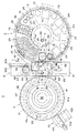
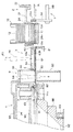
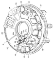
以下、本発明の実施の形態を図面に沿って説明する。この実施形態では生化学分析装置による自動分析装置の例であり、図1は一実施形態の生化学分析装置の概略機構を示す部分断面正面図、図2は生化学分析装置の要部機構の平面図、図3は乾式分析素子の搬送経路部分の断面正面図である。図4はキャリブレータラック非搭載状態のサンプルトレイを示す要部斜視図、図5はキャリブレータ液を収容した容器をセットしたキャリブレータラックの斜視図、図6は空のキャリブレータラックの斜視図、図7は図4のサンプルトレイにキャリブレータラックを搭載した状態の要部斜視図である。
【0024】
図1〜図3により生化学分析装置1の全体構成を説明する。この生化学分析装置1は、サンプルトレイ2、点着部3、第1のインキュベータ4、第2のインキュベータ5、点着装置6、素子搬送機構7、移送機構8、チップ廃却部9、素子廃却機構10などを備えてなる。
【0025】
サンプルトレイ2は円形で、検体を収容した検体容器11、未使用の乾式分析素子12(比色タイプの乾式分析素子および電解質タイプの乾式分析素子)を収容した素子カートリッジ13、消耗品(ノズルチップ14、希釈液容器15、混合カップ16および参照液容器17)を搭載する。なお、検体容器11は検体アダプタ18を介して搭載され、ノズルチップ14はチップラック19に多数収納されて搭載される。
【0026】
点着部3は、サンプルトレイ2の中心線の延長上に配置され、搬送された乾式分析素子12に血漿、全血、血清、尿などの検体の点着が行われるもので、点着装置6によって比色測定タイプの乾式分析素子12には検体を、電解質タイプの乾式分析素子12には検体と参照液を点着する。この点着部3に続いてノズルチップ14が廃却されるチップ廃却部9が配置されている。
【0027】
第1のインキュベータ4は円形で、チップ廃却部9の延長位置に配置され、比色タイプの乾式分析素子12を収容して所定時間恒温保持し、比色測定を行う。第2のインキュベータ5(図2参照)は、点着部3の側方における隣接位置に配設され、電解質タイプの乾式分析素子12を収容して所定時間恒温保持し、電位差測定を行う。
【0028】
素子搬送機構7(図3参照)は、詳細は示していないが、前記サンプルトレイ2の内部に配設され、このサンプルトレイ2の中心と第1のインキュベータ4の中心とを結び、点着部3およびチップ廃却部9を通る直線状の素子搬送経路R(図2)に沿って、乾式分析素子12をサンプルトレイ2の素子カートリッジ13から取り出し点着部3へ、さらに第1のインキュベータ4へ搬送する素子搬送部材71(搬送バー)を備える。素子搬送部材71はガイドロッド38により摺動自在に支持され、不図示の駆動機構によって往復移動操作され、先端部は縦板34のガイド穴34aに挿入され、このガイド穴34aを摺動する。
【0029】
移送機構8は点着部3を兼ねて設置され、点着部3から第2のインキュベータ5へ、素子搬送経路Rと直交する方向に、電解質タイプの乾式分析素子12を移送する。
【0030】
点着装置6は上部に配設され、昇降移動する点着ノズル45が前述の素子搬送経路Rと同一直線上を移動し、検体および参照液の点着、希釈液による検体の希釈混合を行う。点着ノズル45は、先端にノズルチップ14を装着し、該ノズルチップ14内に検体、参照液等を吸引し吐出するもので、その吸引吐出を行う不図示のシリンジ手段が付設され、使用後のノズルチップ14はチップ廃却部9で外されて落下廃却される。
【0031】
素子廃却機構10(図2参照)は第1のインキュベータ4に付設され、測定後の比色タイプの乾式分析素子12を第1のインキュベータ4の中心部に押し出して落下廃棄する。なお、前記素子搬送機構7によって廃却することもできる。また、第2のインキュベータ5で測定した後の電解質タイプの乾式分析素子12は、前記移送機構8によって廃却穴69に廃棄される。
【0032】
また、サンプルトレイ2の近傍には、血液から血漿を分離する不図示の血液濾過ユニットが設置されている。
【0033】
各部の機構を具体的に説明する。まず、サンプルトレイ2は、正転方向および逆転方向に回転駆動される円盤状の回転ディスク21と、その中央部の円盤状の非回転部22とを有する。
【0034】
回転ディスク21には、図2に示すように、各検体を収容した採血管等の検体容器11を検体アダプタ18を介して保持するA〜Eの5つの検体搭載部23と、これに隣接して各検体の測定項目に対応して通常複数の種類が必要とされる未使用の乾式分析素子12を積み重ねた状態で収容した素子カートリッジ13を保持する5つの素子搭載部24と、多数のノズルチップ14を保持孔に並んで収容したチップラック19を保持する2つのチップ搭載部25と、希釈液を収容した3つの希釈液容器15を保持する希釈液搭載部26と、希釈液と検体とを混合するための混合カップ16(多数のカップ状凹部が配置された成形品)を保持するカップ搭載部27とが円弧状に配置されている。
【0035】
さらに、回転ディスク21の内周部には、後述のキャリブレータラック20を搭載するラック搭載部32を備えている。
【0036】
また、非回転部22には、素子搬送経路Rの延長線上で点着ノズル45の移動範囲に、参照液を収容した参照液容器17を保持する筒状の参照液搭載部28を備え、この参照液搭載部28には、参照液容器17の開口部を開閉する蒸発防止蓋35(図1)が設置されている。
【0037】
蒸発防止蓋35は、下端が非回転部22に揺動可能に枢支された支持部材37に保持され、閉方向に付勢されている。支持部材37の上端係止部37aが点着装置6の移動フレーム42の下端角部42aと当接可能であり、参照液の吸引時に近接移動した移動フレーム42により支持部材37が開方向に揺動され、蒸発防止蓋35が参照液容器17を開口して点着ノズル45による参照液吸引が可能となる。その他の状態では蒸発防止蓋35が参照液容器17の開口部を閉塞して参照液の蒸発を防止し、その濃度変化による測定精度の低下を阻止する。
【0038】
前記回転ディスク21は、外周部が支持ローラ31で支持され、中心部が不図示の支持軸に回転自在に保持されている。また、回転ディスク21の外周には、不図示のタイミングベルトが巻き掛けられ、駆動モータによって正転方向または逆転方向に回転駆動される。非回転部22は上記支持軸に回転不能に取り付けられている。
【0039】
前記素子カートリッジ13は、図4にも示すように、四角筒状の箱体の上部が開放し、上方から未使用の乾式分析素子12が混在状態で通常複数枚重ねられて挿入される。下端部の前部には素子取出口13aが開口されている。
【0040】
この素子カートリッジ13が前記素子搭載部24に装填されると、図3に示すように、下端部が素子搭載部24の底壁24aに保持され、素子搬送部材71による素子搬送面と同一高さに最下端部の乾式分析素子12が位置するようになっている。素子カートリッジ13の最下端部の前面側には1枚の乾式分析素子12のみが通過し得る前記素子取出口13aが開口し、後面側には素子搬送部材71が挿通可能な開口13bが形成されている。なお、乾式分析素子12の下面に付設されたバーコード、ドット等によるロット番号などが素子カートリッジ13の下方から読み取れるように底面に窓部が形成されている。
【0041】
また、前記検体アダプタ18は筒状に形成され、上部から検体容器11が挿入される。この検体アダプタ18は、不図示の識別部を有し、検体の種類(処理情報)、検体容器11の種類(サイズ)等の情報が設定され、測定の初期時点でサンプルトレイ2の外周部に配設された識別センサ30(図2)によってその識別が読み取られ、検体の希釈の有無、血漿濾過の有無などが判別されるとともに、検体容器11のサイズに伴う液面変動量が算出され、それに応じた処理制御が行われる。血漿濾過が必要な検体容器11に対しては、アダプタ18に検体容器11を挿入した上に、濾過フィルターを備えたホルダー(不図示)がスペーサ53を介して装着される。
【0042】
点着部3および移送機構8は、サンプルトレイ2と第1のインキュベータ4との間に素子搬送経路Rと直交する方向に長い支持台61を備え、その上に移動可能に摺動枠62が設置されている。この摺動枠62には、点着用開口63a(図3)が形成された第1素子押え63および第2素子押え64が隣接して一体に移動可能に装着されている。第1素子押え63(第2素子押え64も同様)は、支持台61に面する底面に、前記素子移動経路Rに沿って乾式分析素子12が通過する凹部63bを有する。また、摺動枠62は、一端部がガイドバー65に案内され、他端部側の長溝62aにピン66が係合され、さらに、ラックギヤ62bに駆動モータ68の駆動ギヤ67が噛合して移動される。支持台61には、第2のインキュベータ5および廃却穴69が設置されている。
【0043】
そして、図2のように、第1素子押え63が点着部3に位置している際には、点着後の比色タイプの乾式分析素子12は素子搬送機構7の素子搬送部材71によって押し出されて第1のインキュベータ4に移送される。一方、電解質タイプの乾式分析素子12への点着が行われると、摺動枠62が移動されて点着後の乾式分析素子12は第1素子押え63に保持されたまま支持台61上を滑るように第2のインキュベータ5に移送され、電位差測定が行われる。その際には、第2素子押え64が点着部3(点着位置)に移動し、その後に搬送される比色タイプの乾式分析素子12に対する検体の点着および第1のインキュベータ4への搬送が可能である。第2のインキュベータ5での測定が完了すると、摺動枠62がさらに移動されて測定後の乾式分析素子12を廃却穴69に移送して落下廃却する。
【0044】
なお、比色タイプの乾式分析素子12を搬送する際には第2素子押え64を点着部3に移動させておき、電解質タイプの乾式分析素子12が搬送されるときのみ、第1素子押え63を点着部3に移動させるようにしてもよい。
【0045】
点着装置6(図1)は、固定フレーム40の水平ガイドレール41に、横方向に移動可能に保持された移動フレーム42を備え、この移動フレーム42に昇降移動可能に2本の点着ノズル45が設置されている。移動フレーム42には中央に縦ガイドレール43が固着され、この縦ガイドレール43の両側に2つのノズル固定台44が摺動自在に保持されている。ノズル固定台44の下部には、それぞれ点着ノズル45の上端部が固着され、上部に上方に延びる軸状部材が駆動伝達部材47に挿通されている。ノズル固定台44と駆動伝達部材47との間に介装された圧縮バネにより、ノズルチップ14の嵌合力を得るようになっている。ノズル固定台44は駆動伝達部材47と一体に上下移動可能であるとともに、点着ノズル45の先端部にノズルチップ14を嵌合する際に、圧縮バネの圧縮でノズル固定台44に対して駆動伝達部材47が下降移動可能である。上記駆動伝達部材47は、上下のプーリ49に張設されたベルト50に固定され、不図示のモーターによるベルト50の走行に応じて上下移動する。なお、ベルト50の外側部位には、バランスウェイト51が取り付けられ、非駆動時の点着ノズル45の下降移動が防止される。
【0046】
また、移動フレーム42は不図示のベルト駆動機構によって横方向に駆動され、2つのノズル固定台44は独自に上下移動するように、その横移動および上下移動が制御され、2つの点着ノズル45は、一体に横移動するとともに、独自に上下移動するようになっている。例えば、一方の点着ノズル45は検体用であり、他方の点着ノズル45は希釈液用および参照液用である。
【0047】
両点着ノズル45は棒状に形成され、内部に軸方向に延びるエア通路が設けられ、下端にはピペット状のノズルチップ14がシール状態で嵌合される。この点着ノズル45にはそれぞれ不図示のシリンジポンプ等に接続されたエアチューブが連結され、吸引・吐出圧が供給される。また、この吸引圧力の変化に基づき検体等の液面検出が行えるようになっている。
【0048】
チップ廃却部9は、搬送経路Rを上下方向に交差して設けられ、上部材81および下部材82を備える。このチップ廃却部9における前記支持台61には、楕円形に開口された落下口83が形成されている。上部材81は支持台61の上面に固着され、落下口83の直上部位には係合切欠き84が設けられ、下部材82は支持台61の下面に落下口83の下方を囲むように筒状に形成され、落下するノズルチップ14をガイドするようになっている。
【0049】
そして、ノズルチップ14が装着されている点着ノズル45を、上部材81内に下降させてから横方向に移動させ、その係合切欠き84にノズルチップ14の上端を係合してから、点着ノズル45を上昇移動させてノズルチップ14を抜き取り、外れたノズルチップ14は落下口83を通して落下廃却される。
【0050】
次に、比色測定を行う第1のインキュベータ4は、外周部に円環状の回転部材87を備え、この回転部材87は内周下部に固着された傾斜回転筒88が下部のベアリング89に支持されて回転自在である。回転部材87の上部に上位部材90が一体に回転可能に配設されている。上位部材90の底面は平坦であり、回転部材87の上面には円周上に所定間隔で複数(図1の場合13個)の凹部が形成されて両部材87,90間にスリット状空間による素子室91が形成され、この素子室91の底面の高さは搬送面の高さと同一に設けられている。また、傾斜回転筒88の内孔は測定後の乾式分析素子12の廃却孔92に形成され、素子室91の乾式分析素子12がそのまま中心側に移動されて落下廃却される。
【0051】
上位部材90には図示しない加熱手段が配設され、その温度調整によって素子室91内の乾式分析素子12を所定温度に恒温保持する。また上位部材90には素子室91に対応して乾式分析素子12のマウントを上から押えて検体の蒸発防止を行う押え部材93が配設されている。上位部材90の上面には保温カバー94が配設される一方、この第1のインキュベータ4は全体が遮光カバー95によって覆われる。さらに、回転部材87の各素子室91の底面中央には測光用の開口91aが形成され、この開口91aを通して図1に示す位置に配設された測光ヘッド96による乾式分析素子12の反射光学濃度の測定が行われる。第1のインキュベータ4の回転駆動は、不図示のベルト機構により行われ、往復回転駆動される。
【0052】
廃却機構10は、外周側から中心方向に素子室91内に進退移動する廃却バー101を備えている。この廃却バー101は後端部が水平方向に走行するベルト102に固定され、駆動モータ103の駆動によるベルト102の走行に応じ、素子室91から測定後の乾式分析素子12を押し出して廃却する。なお、廃却孔92の下方には測定後の乾式分析素子12を回収する回収箱が配設される。
【0053】
また、イオン活量を測定する第2のインキュベータ5は、前述の摺動枠62の第1素子押え63が上位部材となり、その底部の凹部によって測定本体97の上面との間に1つの素子室が形成される。この第2のインキュベータ5には、図示しない加熱手段が配設され、その温度調整によって乾式分析素子12のイオン活量を測定する部分を所定温度に恒温加熱する。さらに、測定本体97の側辺部にはイオン活量測定のための3対の電位測定用プローブ98が出没して乾式分析素子12のイオン選択電極に接触可能に設けられている。
【0054】
なお、不図示の血漿濾過ユニットは、サンプルトレイ2に保持された検体容器11(採血管)の内部に挿入され上端開口部に取り付けられたガラス繊維からなるフィルターを有する不図示のホルダーを介して血液から血漿を分離吸引し、ホルダー上端のカップ部に濾過された血漿を保持するようになっている。
【0055】
次に、上記のような生化学分析装置1のサンプルトレイ2に対し、キャリブレーションを行う際に使用するキャリブレータ液の搭載機構を、図4〜図7に基づき説明する。本実施形態では、濃度(レベル)が異なる3種類のキャリブレータ液を使用するものであり、このキャリブレータ液はそれぞれ容器55〜57に収容され、キャリブレータラック20によってサンプルトレイ2に搭載される(図7参照)。また、容器55〜57の開口部は、不使用時には蓋55a〜57aで密封されている。
【0056】
キャリブレータラック20は、図5および図6に示すように、前記容器55〜57を載置する複数(3つ)の凹状の容器載置部20aを円弧状に有するとともに、容器55〜57より外された蓋55a〜57aを載置する複数(3つ)の凹状の蓋載置部20bを、容器載置部20aの内周側に1対1に対応して円弧状に有している。
【0057】
また、濃度の異なるキャリブレータ液を収容した複数の容器55〜57には、そのキャリブレータ濃度(レベル)に応じたレベル表示が施され、これに対応して、キャリブレータラック20の複数の容器載置部20aには、上記レベル表示に対応する表示20cが施され、所定の容器搭載部20aに所定レベルの容器55〜57をセットするようになっている。
【0058】
一方、図4に示すように、前記サンプルトレイ2の回転ディスク21における図2のA位置の検体搭載部23および素子搭載部24に近接した内周側部位に、上記キャリブレータラック20を専用に搭載するラック搭載部32が設置されている。このラック搭載部32は、リブ状突起による係合部32aを有し、前記キャリブレータラック20の底面には、この係合部32aと係合する溝による被係合部(不図示)を有し、両者の係合によってサンプルトレイ2にキャリブレータラック20を位置決めするようになっている。
【0059】
なお、上記と逆に、サンプルトレイ2のラック搭載部32には溝による係合部を設け、キャリブレータラック20には突起による被係合部を設けるようにしてもよい。また、それらの形状はピン状突起など、適宜設計変更可能である。
【0060】
そして、図7に示すように、ラック搭載部32にキャリブレータラック20を搭載した状態においては、このキャリブレータラック20の容器載置部20aは、サンプルトレイ2の回転中心より等距離に円弧状に配置されるように設定されている。つまり、回転ディスク21の回転動作に伴い、複数の容器55〜57が常に素子搬送経路Rの一定の位置に停止するようになっており、点着ノズル45によって順に容器55〜57よりキャリブレータ液が吸引される。
【0061】
また、キャリブレーションに必要な乾式分析素子12は、必要枚数を収容した素子カートリッジ13が、ラック搭載部32の近傍の1カ所(図示の場合はA位置)の素子搭載部24にセットされる。
【0062】
そして、キャリブレーション操作は、上記のようにキャリブレータ液を収容した3種類の容器55〜57およびその蓋55a〜57aをセットしたキャリブレータラック20を一括してサンプルトレイ2のラック搭載部32に搭載するとともに、乾式分析素子12を収容した素子カートリッジ13を搭載した後、不図示の操作パネルのキャリブレーションキーを操作することによってキャリブレーションが自動的に開始される。その際、予め、測定するキャリブレータ液のレベル値とレベル数(本数)と1レベルで測定するN数を登録しておく。
【0063】
まず、乾式分析素子12を点着部3に搬送し、その後、点着ノズル45にノズルチップ14を装着してから、キャリブレータラック20の容器55上に移動してそのキャリブレータ液を吸引し、点着部3の乾式分析素子12へ点着し、通常の検体測定時と同様に測定を行う。続いて、次の乾式分析素子12を点着部3に搬送し、サンプルトレイ2を回転作動させて次の容器56を吸引位置へ移動させ、同様にキャリブレータ液を点着し、測定を行うもので、これを3番目の容器57についても行い、これらの既知濃度のキャリブレータ液の測定結果に基づき検量線を補正または作成するキャリブレーションを自動的に行うものである。
【0064】
キャリブレーションが終了したら、サンプルトレイ2よりキャリブレータラック20を取り外し、各容器55〜57
の開口を対応する蓋55a〜57aで閉じ、次のキャリブレーション時まで保管する。
【0065】
上記実施形態では、3種類のキャリブレータ液を用いる場合を示したが、キャリブレーション方式によりその数量は異なる。また、キャリブレータラック20の搭載位置はサンプルトレイ2の検体搭載部23以外であれば特に限定されないが、キャリブレーション測定動作におけるサンプルトレイ2および点着ノズル45の移動を考慮すると図示の内周部位が好適である。また、キャリブレータラック20の形状も適宜設計変更可能であるが、円形のサンプルトレイ2では円弧状がスペース的に好適である。
【図面の簡単な説明】
【図1】本発明の一実施形態の生化学分析装置の概略構成を示す部分断面正面図
【図2】図1の要部機構の平面図
【図3】図1の乾式分析素子の搬送経路部分の断面正面図
【図4】キャリブレータラック非搭載状態のサンプルトレイを示す要部斜視図
【図5】キャリブレータ液を収容した容器をセットしたキャリブレータラックの斜視図
【図6】空のキャリブレータラックの斜視図
【図7】図4のサンプルトレイにキャリブレータラックを搭載した状態の要部斜視図
【符号の説明】
1 生化学分析装置
2 サンプルトレイ
3 点着部
7 素子搬送機構
11 検体容器
12 乾式分析素子
13 素子カートリッジ
20 キャリブレータラック
20a 容器載置部
20b 蓋載置部
20c 表示
21 回転ディスク
23 検体搭載部
24 素子搭載部
32 ラック搭載部
32a 係合部
55〜57 容器
55a〜57a 蓋[0001]
BACKGROUND OF THE INVENTION
In the present invention, a specimen such as blood or urine is spotted on a dry analytical element such as a colorimetric type dry analytical element or an electrolyte type, and a component such as a substance concentration or ion activity of a predetermined biochemical substance in the specimen In particular, the present invention relates to a mechanism for mounting a calibrator liquid for performing calibration.
[0002]
[Prior art]
Conventionally, a specific color component of a dry analytical element or sample that can quantitatively analyze a specific chemical component or formed component contained in this sample simply by spotting and supplying a small droplet of the sample An electrolyte type dry analytical element capable of measuring ion activity of ions has been developed and put into practical use. Biochemical analyzers using these dry analytical elements are suitable for use in medical institutions, laboratories and the like because they can easily and quickly analyze samples.
[0003]
In the colorimetric measurement method using a colorimetric type dry analytical element, after a sample is spotted on the dry analytical element, the sample is held at a constant temperature in an incubator for a color reaction (dye generation reaction), and then the sample The dry analytical element is irradiated with measurement irradiation light containing a wavelength selected in advance by a combination of a predetermined biochemical substance and a reagent contained in the dry analytical element, and the optical density is measured. The concentration of the biochemical substance is obtained using a calibration curve representing the correspondence between the optical density obtained in advance and the substance concentration of the predetermined biochemical substance.
[0004]
On the other hand, the potential difference measurement method using an electrolyte type dry analytical element is included in a sample spotted on an electrode pair consisting of two pairs of the same kind of dry ion selective electrodes instead of measuring the above optical density. The activity of specific ions is determined by quantitative analysis with potentiometry using a reference solution.
[0005]
In any of the above methods, a liquid sample is stored in a sample container (such as a blood collection tube) and set in the apparatus, and a dry analytical element necessary for the measurement is mounted on the apparatus, and the dry analytical element is mounted from the mounting position. While being transported to the landing part and the incubator, the specimen is supplied from the mounting position to the spotting part by the spotting nozzle of the spotting apparatus and spotted to the dry analytical element.
[0006]
In addition, the dry analytical element used in the above analysis has a calibrator containing a detection component with a known concentration from the viewpoint of ensuring measurement accuracy, for example, because the characteristics of the contained reagent change minutely if the production lot is different. The liquid is spotted on a dry analytical element and measured, and based on the measurement, the above-described calibration curve is corrected or newly created calibration is performed (for example, refer to Patent Document 1).
[0007]
A plurality of types of calibrator liquids required for the calibration are usually used, and a container containing the calibrator liquid is mounted on the sample container mounting portion of the automatic analyzer instead of the sample. Is generally done. In a large analyzer, a part of the sample mounting part is exclusively used for the calibrator mounting part.
[0008]
[Patent Document 1]
Japanese Patent Laid-Open No. 10-19784
[0009]
[Problems to be solved by the invention]
By the way, in the case where the calibrator liquid is set in the sample mounting portion where the sample is set in the normal general measurement and is measured instead of the general sample as described above, in which position when a plurality of calibrator liquids are set. The calibration operation, such as which level (concentration) of the calibrator liquid to set, becomes complicated, and there is a risk of erroneous operation.
[0010]
In addition, when a part of the specimen mounting part is exclusively used for the calibrator solution, calibration is not an operation that is frequently performed. Therefore, the number of specimens that can be mounted is reduced, the measurement efficiency is lowered, and the apparatus is downsized. It becomes an obstacle.
[0011]
In view of this point, the present invention has an object to provide an automatic analyzer that improves the mountability of a calibrator liquid on a sample tray, improves operability, and increases the space efficiency of the sample tray. is there.
[0012]
[Means for Solving the Problems]
The automatic analyzer of the present invention includes a sample tray on which a specimen and a dry analytical element necessary for the measurement are mounted, and the specimen loaded on the sample tray is spotted on the dry analytical element to measure the component concentration, and the known concentration In the automatic analyzer that calibrates the calibration curve based on the measurement result, the container containing the calibrator liquid is set in the sample tray and measured in the same manner.
It comprises a calibrator rack for mounting a plurality of containers containing the calibrator liquid, and the sample tray is provided with a rack mounting portion for mounting the calibrator rack exclusively at a position different from the sample mounting portion. Is.
[0013]
The calibrator rack preferably has a mounting portion for a lid removed from a plurality of containers containing calibrator liquids.
[0014]
Preferably, the rack mounting portion of the sample tray has an engaging portion by a protrusion or a groove, and the calibrator rack has an engaged portion by a groove or a protrusion that engages with the engaging portion, and is positioned.
[0015]
It is preferable to perform measurement by setting a plurality of dry analysis elements necessary for calibration in one element mounting part in the vicinity of the rack mounting part.
[0016]
The container mounting portion of the calibrator rack is preferably arranged in an arc shape at an equal distance from the rotation center of the sample tray in a state where the rack is set on the sample tray.
[0017]
The rack mounting portion of the sample tray is preferably disposed on the inner peripheral side of the sample mounting portion.
[0018]
【The invention's effect】
According to the present invention as described above, when calibration is performed, a plurality of containers containing calibrator liquids are mounted on the calibrator rack, and the calibrator rack is dedicated to a position different from the sample mounting portion of the sample tray. By mounting it on the rack mounting part installed in, it is possible to clarify the setting position of multiple levels of containers, and it is possible to set it on the apparatus in a lump, improving the mountability of calibrator liquid on the sample tray In addition, operability can be improved.
[0019]
In addition, by mounting the calibrator solution separately from the sample mounting unit that sets the sample for normal general measurement, it does not occupy space during normal measurement, ensuring space efficiency and ensuring the number of samples that can be mounted. Measurement efficiency is improved and the apparatus can be miniaturized.
[0020]
If the calibrator rack has a mounting part for the lid removed from the container, the container and its lid can be placed in correspondence with each other, and it is possible to prevent the lid from being misplaced and attached. Can prevent contamination and maintain calibration accuracy.
[0021]
The rack mounting part of the sample tray has an engaging part by a protrusion or groove and is positioned by being engaged with the engaged part by the groove or protrusion of the calibrator rack. Suction operation can be performed without any problem, and it is excellent in mountability.
[0022]
If a plurality of dry analytical elements required for calibration are set in one element mounting part in the vicinity of the rack mounting part, even if there are a plurality of calibrator solutions, there is only one type of dry analytical element for measurement. Therefore, the mounting property is excellent and the operability can be simplified.
[0023]
DETAILED DESCRIPTION OF THE INVENTION
Hereinafter, embodiments of the present invention will be described with reference to the drawings. In this embodiment, it is an example of the automatic analyzer by a biochemical analyzer, FIG. 1 is a partial cross-sectional front view showing a schematic mechanism of the biochemical analyzer of one embodiment, and FIG. FIG. 3 is a cross-sectional front view of the transport path portion of the dry analytical element. 4 is a perspective view of a main part showing a sample tray in a state where the calibrator rack is not mounted, FIG. 5 is a perspective view of a calibrator rack in which a container containing calibrator liquid is set, FIG. 6 is a perspective view of an empty calibrator rack, and FIG. FIG. 5 is a perspective view of a main part in a state where a calibrator rack is mounted on the sample tray of FIG. 4.
[0024]
The overall configuration of the
[0025]
The
[0026]
The
[0027]
The first incubator 4 has a circular shape and is disposed at an extended position of the
[0028]
The element transport mechanism 7 (see FIG. 3), which is not shown in detail, is disposed inside the
[0029]
The
[0030]
The spotting device 6 is disposed in the upper part, and a spotting
[0031]
The element discarding mechanism 10 (see FIG. 2) is attached to the first incubator 4 and pushes the colorimetric dry
[0032]
In addition, a blood filtration unit (not shown) that separates plasma from blood is installed in the vicinity of the
[0033]
The mechanism of each part will be specifically described. First, the
[0034]
As shown in FIG. 2, the
[0035]
Further, a
[0036]
Further, the
[0037]
The
[0038]
The
[0039]
As shown in FIG. 4, the
[0040]
When the
[0041]
The
[0042]
The
[0043]
As shown in FIG. 2, when the
[0044]
When the colorimetric type dry
[0045]
The spotting device 6 (FIG. 1) includes a moving
[0046]
The moving
[0047]
Both the spotting
[0048]
The
[0049]
Then, the spotting
[0050]
Next, the first incubator 4 that performs colorimetric measurement includes an annular rotating
[0051]
The
[0052]
The
[0053]
Further, in the second incubator 5 for measuring the ion activity, the
[0054]
A plasma filtration unit (not shown) is inserted through a holder (not shown) having a filter made of glass fiber inserted into the sample container 11 (collecting blood vessel) held in the
[0055]
Next, the mounting mechanism of the calibrator liquid used when calibrating the
[0056]
As shown in FIGS. 5 and 6, the
[0057]
Further, a plurality of
[0058]
On the other hand, as shown in FIG. 4, the
[0059]
Conversely, the
[0060]
As shown in FIG. 7, in a state where the
[0061]
In addition, the dry
[0062]
In the calibration operation, the three types of
[0063]
First, the dry
[0064]
When calibration is completed, the
Are closed with the corresponding
[0065]
In the above-described embodiment, the case where three types of calibrator liquids are used has been described, but the quantity varies depending on the calibration method. The mounting position of the
[Brief description of the drawings]
FIG. 1 is a partial cross-sectional front view showing a schematic configuration of a biochemical analyzer according to an embodiment of the present invention.
FIG. 2 is a plan view of the main part mechanism of FIG.
3 is a cross-sectional front view of a transport path portion of the dry analytical element of FIG.
FIG. 4 is a perspective view of a main part showing a sample tray in a state where a calibrator rack is not mounted.
FIG. 5 is a perspective view of a calibrator rack in which a container containing calibrator liquid is set.
FIG. 6 is a perspective view of an empty calibrator rack.
7 is a perspective view of a main part in a state where a calibrator rack is mounted on the sample tray of FIG. 4;
[Explanation of symbols]
1 Biochemical analyzer
2 Sample tray
3 point landing
7 Element transport mechanism
11 Sample container
12 Dry analytical element
13 element cartridge
20 Calibrator rack
20a Container placement part
20b Lid placement part
20c display
21 Rotating disc
23 Sample mounting section
24 element mounting part
32 Rack mounting part
32a engaging part
55-57 containers
55a-57a lid
Claims (6)
前記キャリブレータ液を収容した複数の容器を搭載するキャリブレータラックを備え、前記サンプルトレイは検体搭載部とは異なる位置に、前記キャリブレータラックを専用に搭載するラック搭載部を備えてなることを特徴とする自動分析装置。A sample tray equipped with a specimen and a dry analytical element necessary for the measurement is provided. The specimen loaded in the sample tray is spotted on the dry analytical element to measure the component concentration, and a container containing a calibrator solution of a known concentration is provided. In the automatic analyzer for setting the sample tray and measuring in the same manner, and calibrating the calibration curve based on the measurement result,
A calibrator rack for mounting a plurality of containers containing the calibrator liquid is provided, and the sample tray is provided with a rack mounting portion for mounting the calibrator rack exclusively at a position different from the sample mounting portion. Automatic analyzer.
Priority Applications (1)
| Application Number | Priority Date | Filing Date | Title |
|---|---|---|---|
| JP2003006007A JP2004219218A (en) | 2003-01-14 | 2003-01-14 | Automatic analyzer |
Applications Claiming Priority (1)
| Application Number | Priority Date | Filing Date | Title |
|---|---|---|---|
| JP2003006007A JP2004219218A (en) | 2003-01-14 | 2003-01-14 | Automatic analyzer |
Publications (2)
| Publication Number | Publication Date |
|---|---|
| JP2004219218A true JP2004219218A (en) | 2004-08-05 |
| JP2004219218A5 JP2004219218A5 (en) | 2005-09-08 |
Family
ID=32896523
Family Applications (1)
| Application Number | Title | Priority Date | Filing Date |
|---|---|---|---|
| JP2003006007A Pending JP2004219218A (en) | 2003-01-14 | 2003-01-14 | Automatic analyzer |
Country Status (1)
| Country | Link |
|---|---|
| JP (1) | JP2004219218A (en) |
Cited By (5)
| Publication number | Priority date | Publication date | Assignee | Title |
|---|---|---|---|---|
| JP2006125898A (en) * | 2004-10-27 | 2006-05-18 | Hitachi High-Technologies Corp | Proportionality verification reagent vessel in automatic analyzer and reagent kit using it |
| WO2006123660A1 (en) * | 2005-05-17 | 2006-11-23 | Wako Pure Chemical Industries, Ltd. | Connected reagent container |
| JP2009085916A (en) * | 2007-10-03 | 2009-04-23 | Toshiba Corp | Automatic analysis apparatus and sample container |
| CN104076160A (en) * | 2013-03-28 | 2014-10-01 | 希森美康株式会社 | Sample analyzer, transporting apparatus, and lid placing tray |
| CN111239426A (en) * | 2018-11-29 | 2020-06-05 | 深圳市帝迈生物技术有限公司 | Sample analyzer and automatic calibration method thereof |
Citations (15)
| Publication number | Priority date | Publication date | Assignee | Title |
|---|---|---|---|---|
| JPS57105970U (en) * | 1980-12-22 | 1982-06-30 | ||
| JPS6136559U (en) * | 1984-08-07 | 1986-03-06 | 株式会社島津製作所 | automatic analyzer |
| JPS63292064A (en) * | 1987-05-06 | 1988-11-29 | アボット・ラボラトリーズ | Material receiver for automatic clinical analyzer |
| JPH0259671A (en) * | 1988-08-26 | 1990-02-28 | Hitachi Ltd | Immunoassay |
| JPH02159564A (en) * | 1988-12-12 | 1990-06-19 | Jeol Ltd | Divided-type sample turntable |
| JPH02269970A (en) * | 1988-08-26 | 1990-11-05 | E I Du Pont De Nemours & Co | Method and equipment for performing automatic analysis test of sample |
| JPH0312166U (en) * | 1989-06-23 | 1991-02-07 | ||
| JPH04164257A (en) * | 1990-10-29 | 1992-06-09 | Ajinomoto Co Inc | Automatic pretreatment device |
| JPH05172829A (en) * | 1991-06-03 | 1993-07-13 | Abbott Lab | Reagent pack for immunological assay |
| JPH05196626A (en) * | 1991-06-26 | 1993-08-06 | Boehringer Mannheim Gmbh | Analyzer for automatic analysis of body fluid |
| JPH05302924A (en) * | 1992-04-28 | 1993-11-16 | Olympus Optical Co Ltd | Reagent container for automatic analyzer |
| JPH07505475A (en) * | 1992-03-27 | 1995-06-15 | アボツト・ラボラトリーズ | Methods of validating assay results and operating automated continuous random access analysis systems |
| JPH085639A (en) * | 1994-06-20 | 1996-01-12 | Olympus Optical Co Ltd | Automatic blood analyzer |
| JPH1019784A (en) * | 1995-05-19 | 1998-01-23 | Fuji Photo Film Co Ltd | Two step calibration method employing dry analytical element |
| JP2002181832A (en) * | 2000-12-13 | 2002-06-26 | Fuji Photo Film Co Ltd | Cartridge for biochemical analysis |
-
2003
- 2003-01-14 JP JP2003006007A patent/JP2004219218A/en active Pending
Patent Citations (15)
| Publication number | Priority date | Publication date | Assignee | Title |
|---|---|---|---|---|
| JPS57105970U (en) * | 1980-12-22 | 1982-06-30 | ||
| JPS6136559U (en) * | 1984-08-07 | 1986-03-06 | 株式会社島津製作所 | automatic analyzer |
| JPS63292064A (en) * | 1987-05-06 | 1988-11-29 | アボット・ラボラトリーズ | Material receiver for automatic clinical analyzer |
| JPH0259671A (en) * | 1988-08-26 | 1990-02-28 | Hitachi Ltd | Immunoassay |
| JPH02269970A (en) * | 1988-08-26 | 1990-11-05 | E I Du Pont De Nemours & Co | Method and equipment for performing automatic analysis test of sample |
| JPH02159564A (en) * | 1988-12-12 | 1990-06-19 | Jeol Ltd | Divided-type sample turntable |
| JPH0312166U (en) * | 1989-06-23 | 1991-02-07 | ||
| JPH04164257A (en) * | 1990-10-29 | 1992-06-09 | Ajinomoto Co Inc | Automatic pretreatment device |
| JPH05172829A (en) * | 1991-06-03 | 1993-07-13 | Abbott Lab | Reagent pack for immunological assay |
| JPH05196626A (en) * | 1991-06-26 | 1993-08-06 | Boehringer Mannheim Gmbh | Analyzer for automatic analysis of body fluid |
| JPH07505475A (en) * | 1992-03-27 | 1995-06-15 | アボツト・ラボラトリーズ | Methods of validating assay results and operating automated continuous random access analysis systems |
| JPH05302924A (en) * | 1992-04-28 | 1993-11-16 | Olympus Optical Co Ltd | Reagent container for automatic analyzer |
| JPH085639A (en) * | 1994-06-20 | 1996-01-12 | Olympus Optical Co Ltd | Automatic blood analyzer |
| JPH1019784A (en) * | 1995-05-19 | 1998-01-23 | Fuji Photo Film Co Ltd | Two step calibration method employing dry analytical element |
| JP2002181832A (en) * | 2000-12-13 | 2002-06-26 | Fuji Photo Film Co Ltd | Cartridge for biochemical analysis |
Cited By (10)
| Publication number | Priority date | Publication date | Assignee | Title |
|---|---|---|---|---|
| JP2006125898A (en) * | 2004-10-27 | 2006-05-18 | Hitachi High-Technologies Corp | Proportionality verification reagent vessel in automatic analyzer and reagent kit using it |
| WO2006123660A1 (en) * | 2005-05-17 | 2006-11-23 | Wako Pure Chemical Industries, Ltd. | Connected reagent container |
| JP2009085916A (en) * | 2007-10-03 | 2009-04-23 | Toshiba Corp | Automatic analysis apparatus and sample container |
| CN104076160A (en) * | 2013-03-28 | 2014-10-01 | 希森美康株式会社 | Sample analyzer, transporting apparatus, and lid placing tray |
| US20140294673A1 (en) * | 2013-03-28 | 2014-10-02 | Sysmex Corporation | Sample analyzer, transporting apparatus, and lid placing tray |
| JP2014190907A (en) * | 2013-03-28 | 2014-10-06 | Sysmex Corp | Specimen analyzer, transport device, and lid placing tray |
| US9702888B2 (en) | 2013-03-28 | 2017-07-11 | Sysmex Corporation | Sample analyzer, transporting apparatus, and lid placing tray |
| EP2784517B1 (en) * | 2013-03-28 | 2021-01-06 | Sysmex Corporation | Sample analyzer |
| CN111239426A (en) * | 2018-11-29 | 2020-06-05 | 深圳市帝迈生物技术有限公司 | Sample analyzer and automatic calibration method thereof |
| CN111239426B (en) * | 2018-11-29 | 2023-12-01 | 深圳市帝迈生物技术有限公司 | Sample analyzer and automatic calibration method thereof |
Similar Documents
| Publication | Publication Date | Title |
|---|---|---|
| US4338279A (en) | Automatic analyzing apparatus | |
| US20020098116A1 (en) | Biochemical analysis system, and biochemical analysis element cartridge | |
| JP4181052B2 (en) | Automatic analyzer | |
| JP2004219218A (en) | Automatic analyzer | |
| JP2003329691A (en) | Biochemical analyzer | |
| JP2002181834A (en) | Cartridge for biochemical analysis | |
| JP2003329695A (en) | Biochemical analyzer | |
| JP3899370B2 (en) | Automatic analyzer | |
| JP3919107B2 (en) | Automatic analyzer | |
| JP4132756B2 (en) | Biochemical analyzer | |
| JP5634969B2 (en) | Biochemical analyzer and rotational conveyance method | |
| JP4475570B2 (en) | Centrifuge built-in analyzer | |
| JP2005009868A (en) | Autoanalyzer | |
| JP3850215B2 (en) | Biochemical analyzer | |
| JP3853741B2 (en) | incubator | |
| JP4142278B2 (en) | Biochemical analyzer | |
| JP3682029B2 (en) | Biochemical analyzer | |
| JP4094234B2 (en) | incubator | |
| US20020090322A1 (en) | Incubator | |
| JP2000258437A (en) | Leak detection method of biochemical analyzer and liquid suction discharge device | |
| JP2000266766A (en) | Biochemical analyzer | |
| JP2003287544A (en) | Biochemical analyzer | |
| JP2002181832A (en) | Cartridge for biochemical analysis | |
| JP2003075456A (en) | Spottedly sticking device for biochemical analyzer | |
| JP3688502B2 (en) | Biochemical analyzer |
Legal Events
| Date | Code | Title | Description |
|---|---|---|---|
| A521 | Written amendment |
Free format text: JAPANESE INTERMEDIATE CODE: A523 Effective date: 20050316 |
|
| A621 | Written request for application examination |
Free format text: JAPANESE INTERMEDIATE CODE: A621 Effective date: 20050316 |
|
| A977 | Report on retrieval |
Free format text: JAPANESE INTERMEDIATE CODE: A971007 Effective date: 20060425 |
|
| A131 | Notification of reasons for refusal |
Free format text: JAPANESE INTERMEDIATE CODE: A131 Effective date: 20060530 |
|
| A521 | Written amendment |
Free format text: JAPANESE INTERMEDIATE CODE: A523 Effective date: 20060727 |
|
| A711 | Notification of change in applicant |
Free format text: JAPANESE INTERMEDIATE CODE: A712 Effective date: 20061205 |
|
| A02 | Decision of refusal |
Free format text: JAPANESE INTERMEDIATE CODE: A02 Effective date: 20070313 |