JP3853741B2 - incubator - Google Patents
incubator Download PDFInfo
- Publication number
- JP3853741B2 JP3853741B2 JP2003016384A JP2003016384A JP3853741B2 JP 3853741 B2 JP3853741 B2 JP 3853741B2 JP 2003016384 A JP2003016384 A JP 2003016384A JP 2003016384 A JP2003016384 A JP 2003016384A JP 3853741 B2 JP3853741 B2 JP 3853741B2
- Authority
- JP
- Japan
- Prior art keywords
- dry analytical
- analytical element
- block
- incubator
- spotting
- Prior art date
- Legal status (The legal status is an assumption and is not a legal conclusion. Google has not performed a legal analysis and makes no representation as to the accuracy of the status listed.)
- Expired - Fee Related
Links
Images


Description
【0001】
【発明の属する技術分野】
本発明は、血液、尿等の検体を乾式分析素子に点着し、検体中の所定の生化学物質の物質濃度、イオン活量等を求める生化学分析装置に使用され、点着後の乾式分析素子を所定温度に恒温保持するインキュベータに関するものである。
【0002】
【従来の技術】
従来より、検体の小滴を点着供給するだけでこの検体中に含まれている特定の化学成分または有形成分を定量分析することのできる比色タイプの乾式分析素子や検体に含まれる特定イオンのイオン活量を測定することのできる電解質タイプの乾式分析素子が開発され、実用化されている。これらの乾式分析素子を用いた生化学分析装置は、簡単かつ迅速に検体の分析を行うことができるので、医療機関、研究所等において好適に用いられている。
【0003】
比色タイプの乾式分析素子を使用する比色測定法は、検体を乾式分析素子に点着させた後、これをインキュベータ内で所定時間恒温保持して呈色反応(色素生成反応)させ、次いで検体中の所定の生化学物質と乾式分析素子に含まれる試薬との組み合わせにより予め選定された波長を含む測定用照射光をこの乾式分析素子に照射してその光学濃度を測定し、この光学濃度から、予め求めておいた光学濃度と所定の生化学物質の物質濃度との対応を表す検量線を用いて該生化学物質の濃度を求めるものである。一方、電解質タイプの乾式分析素子を使用する電位差測定法は、上記の光学濃度を測定する代わりに、同種の乾式イオン選択電極の2個1組からなる電極対に点着された検体中に含まれる特定イオンの活量を、参照液を用いてポテンシオメトリで定量分析することにより求めるものである。
【0004】
上記いずれの方法においても、検体が点着された乾式分析素子は、測定中は一定温度に恒温保持することが測定精度を確保する上で必要であり、この恒温保持のためにインキュベータが使用され、例えば、比色タイプの乾式分析素子を37±0.2℃に恒温保持し、電解質タイプの乾式分析素子を30±1℃に恒温保持する。
【0005】
そして、上記のようなインキュベータによる乾式分析素子の加熱方法は、例えば、特許文献1に見られるように、乾式分析素子の接触する部分と乾式分析素子自体を一定の温度に保ったチャンバーに閉じこめ、全体を加熱するもの、または、特許文献2に見られるように、上ベース部に上下方向に形成された摺動孔に押え部材を保持すると共に、この上ベース部にヒーターを設置し、摺動孔の内面から押え部材に熱を供給して乾式分析素子を加熱するものが知られている。
【0006】
【特許文献1】
米国特許第4,298,571号明細書
【0007】
【特許文献2】
特開平5−223829号公報
【0008】
【発明が解決しようとする課題】
ところで、インキュベータに挿入された乾式分析素子は、所定温度へ加熱した後の所定時間後、または所定時間毎にその測定を行うものであり、寒冷時等で収容前の乾式分析素子の温度が低い場合に、所定温度に到達するまでに多くの時間がかかると、測定精度に影響を与える問題を有する。
【0009】
前述の特許文献1の加熱方法では、インキュベータ内を密閉して加熱するため、所定温度に温調されている素子室へ冷たい乾式分析素子を入れても、熱の供給が空気加熱のため伝熱効率が低くて昇温速度が遅く、所定温度に到達するまでに時間がかかってしまう。また、特許文献2の加熱方法では、押え部材が乾式分析素子に接することでこの部分の伝熱効率は良好であるが、乾式分析素子の加熱が上方からのみであるために、まだ昇温速度が遅く、所定温度に到達するまでに時間がかかってしまう。
【0010】
上記点からは、乾式分析素子の上下に温調ブロックを配置し、この温調ブロックで乾式分析素子を挟み、両面から加熱することが加熱時間を短縮する点では有効であるが、上下の温調ブロックにそれぞれ温度を一定に管理するヒーターを設置することは、ヒーターが複数必要になるなど装置が複雑になる。
【0011】
本発明はかかる点に鑑み、寒冷時等においても乾式分析素子に効率よく熱を供給して速やかに所定温度に加熱可能なインキュベータを提供することを目的とするものである。
【0012】
【課題を解決するための手段】
本発明のインキュベータは、検体が点着された乾式分析素子を収容して所定温度に恒温保持するインキュベータにおいて、
前記乾式分析素子を上下から挟む少なくとも下ブロックが接離移動可能な上ブロックおよび下ブロックを備え、前記下ブロックのみにヒーターを設置して温度調整し、前記乾式分析素子を収容する前に、前記下ブロックと前記上ブロックとを接触させ、該上ブロックを伝熱により予熱し、前記下ブロックと前記上ブロックとの間に乾式分析素子を収容した後、前記下ブロックと前記上ブロックとの間で乾式分析素子を挟み、両ブロックの熱によって乾式分析素子を加熱することを特徴とするものである。
【0014】
前記乾式分析素子は、検体のイオン活量を測定する電解質タイプの乾式分析素子であり、前記下ブロックに電位測定用プローブが設けられているものが好ましい。
【0015】
また、金属材料よりなり、前記上ブロックを覆うカバーをさらに備え、該カバーの上ブロックと接触する部位に断熱材が設置されているものが好適である。その際、前記カバーの断熱材に凹部が形成されてなるものが好ましい。
【0016】
一方、前記上ブロックを予熱する予熱時間を、環境温度に応じて変更することが好ましく、環境温度が低いときには、予熱時間を長く設定する。
【0017】
【発明の効果】
上記のような本発明によれば、乾式分析素子を収容する前に、ヒーターを備えた一方のブロックによって、ヒーターを有さない他方のブロックを予熱しておくことにより、ヒーターを複数使用せずに簡易な構造によって、乾式分析素子を収容と同時にその両面に接触する両ブロックによって効率よく加熱でき、寒冷時等において冷たい乾式分析素子が挿入されても短時間で所定温度に到達させることができ、精度のよい測定が行えると共に、コスト面で有利となる。特に、環境の温度差による、素子温度の上昇時間の差を少なくでき、測定効率の向上が図れる。
【0018】
また、電解質タイプの乾式分析素子に対するインキュベータに適用すると、乾式分析素子に測定用プローブを当接させるための移動機構によって同時に下ブロックと上ブロックとを相対的に接離移動させるように構成でき、機構上有利である。
【0019】
前記上ブロックを覆うカバーに断熱材を備えたものでは、上ブロックからカバーへ逃げる熱量を低減して予熱効率を高め、この上ブロックの予熱を迅速に行って予熱時間の短縮を図るとともに、乾式分析素子の所定温度への維持を精度よく行え、さらに、金属よりなるカバーのシールド作用により微弱な電気量の測定精度を高めることができる。上記断熱材に凹部を設けると、上カバーとの接触面積が低減して断熱効果がより高まり、予熱効率の向上がれ図れる。
【0020】
また、環境温度に応じて予熱時間を変化させるものでは、乾式分析素子の温度精度を高めて測定精度の向上が図れる。
【0021】
【発明の実施の形態】
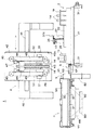
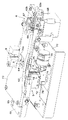
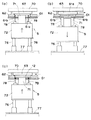
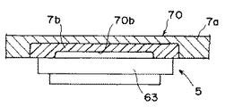
以下、本発明の実施の形態を図面に沿って説明する。図1は一実施形態の生化学分析装置の概略機構を示す部分断面正面図、図2は図1の生化学分析装置の要部機構の平面図である。図3は本発明の一実施形態のインキュベータ部分の斜視図、図4は図3のカバーを外した状態の斜視図、図5は図4の下ブロックが下降した状態を示す同斜視図、図6はインキュベータの動作状態をそれぞれ示す一部断面正面図である。また、図7および図8はカバーの構造例を示す要部断面図でる。
【0022】
図1および図2により生化学分析装置1の全体構成を説明する。この生化学分析装置1は、サンプルトレイ2、点着部3、比色測定用の第1のインキュベータ4、本発明の対象となる電位測定用の第2のインキュベータ5(図2)、点着装置6、不図示の素子搬送機構、移送機構8、チップ廃却部9、素子廃却機構10などを備えてなる。
【0023】
サンプルトレイ2は円形で、検体を収容した検体容器11、未使用の乾式分析素子12(比色タイプの乾式分析素子および電解質タイプの乾式分析素子)を収容した素子カートリッジ13、消耗品(ノズルチップ14、希釈液容器15、混合カップ16および参照液容器17)を搭載する。なお、検体容器11は検体アダプタ18を介して搭載され、ノズルチップ14はチップラック19に多数収納されて搭載される。
【0024】
点着部3は、サンプルトレイ2の中心線の延長上に配置され、搬送された乾式分析素子12に血漿、全血、血清、尿などの検体の点着が行われるもので、点着装置6によって比色測定タイプの乾式分析素子12には検体を、電解質タイプの乾式分析素子12には検体と参照液を点着する。この点着部3に続いてノズルチップ14が廃却されるチップ廃却部9が配置されている。
【0025】
第1のインキュベータ4は円形で、チップ廃却部9の延長位置に配置され、比色タイプの乾式分析素子12を収容して所定時間恒温保持し、比色測定を行う。第2のインキュベータ5(詳細は図3〜図8により後述する)は、点着部3の側方における隣接位置に配設され、電解質タイプの乾式分析素子12を収容して所定時間恒温保持し、電位差測定を行う。
【0026】
不図示の素子搬送機構は、前記サンプルトレイ2の内部に配設され、このサンプルトレイ2の中心と第1のインキュベータ4の中心とを結び、点着部3およびチップ廃却部9を通る直線状の素子搬送経路R(図2)に沿って、乾式分析素子12をサンプルトレイ2から点着部3へ、さらに第1のインキュベータ4へ搬送する素子搬送部材(搬送バー)を備える。移送機構8は点着部3を兼ねて設置され、点着部3から第2のインキュベータ5へ、素子搬送経路Rと直交する方向に、電解質タイプの乾式分析素子12を移送する。
【0027】
点着装置6は上部に配設され、昇降移動する点着ノズル45が前述の素子搬送経路Rと同一直線上を移動し、検体および参照液の点着、希釈液による検体の希釈混合を行う。点着ノズル45は、先端にノズルチップ14を装着し、該ノズルチップ14内に検体、参照液等を吸引し吐出するもので、その吸引吐出を行う不図示のシリンジ手段が付設され、使用後のノズルチップ14はチップ廃却部9で外されて落下廃却される。
【0028】
素子廃却機構10(図2参照)は第1のインキュベータ4に付設され、測定後の比色タイプの乾式分析素子12を第1のインキュベータ4の中心部に押し出して落下廃棄する。なお、前記素子搬送機構によって廃却することもできる。また、第2のインキュベータ5で測定した後の電解質タイプの乾式分析素子12は、前記移送機構8によって廃却穴69に廃棄される。
【0029】
また、サンプルトレイ2の近傍には、血液から血漿を分離する不図示の血液濾過ユニットが設置されている。
【0030】
各部の機構を具体的に説明する。まず、サンプルトレイ2は、正転方向および逆転方向に回転駆動される円盤状の回転ディスク21と、その中央部の円盤状の非回転部22とを有する。
【0031】
回転ディスク21には、図2に示すように、各検体を収容した採血管等の検体容器11を検体アダプタ18を介して保持するA〜Eの5つの検体搭載部23と、これに隣接して各検体の測定項目に対応して通常複数の種類が必要とされる未使用の乾式分析素子12を積み重ねた状態で収容した素子カートリッジ13を保持する5つの素子搭載部24と、多数のノズルチップ14を保持孔に並んで収容したチップラック19を保持する2つのチップ搭載部25と、希釈液を収容した3つの希釈液容器15を保持する希釈液搭載部26と、希釈液と検体とを混合するための混合カップ16(多数のカップ状凹部が配置された成形品)を保持するカップ搭載部27とが円弧状に配置されている。
【0032】
また、非回転部22には、素子搬送経路Rの延長上で点着ノズル45の移動範囲に、参照液を収容した参照液容器17を保持する筒状の参照液搭載部28を備え、この参照液搭載部28には、参照液容器17の開口部を開閉する蒸発防止蓋35(図1)が設置されている。
【0033】
蒸発防止蓋35は、下端が非回転部22に揺動可能に枢支された揺動部材37に保持され、閉方向に付勢されている。揺動部材37の上端係止部37aが点着装置6の移動フレーム42の下端角部42aと当接可能であり、参照液の吸引時に近接移動した移動フレーム42により揺動部材37が開方向に揺動され、蒸発防止蓋35が参照液容器17を開口して点着ノズル45による参照液吸引が可能となる。その他の状態では蒸発防止蓋35が参照液容器17の開口部を閉塞して参照液の蒸発を防止し、その濃度変化による測定精度の低下を阻止する。
【0034】
前記回転ディスク21は、外周部が支持ローラ31で支持され、中心部が不図示の支持軸に回転自在に保持されている。また、回転ディスク21の外周には、不図示のタイミングベルトが巻き掛けられ、駆動モータによって正転方向または逆転方向に回転駆動される。非回転部22は上記支持軸に回転不能に取り付けられている。
【0035】
前記素子カートリッジ13は、上方から未使用の乾式分析素子12が混在状態で通常複数枚重ねられて挿入され、前記素子搭載部24に装填されると、素子搬送面と同一高さに最下端部の乾式分析素子12が位置し、最下端部の前面側には1枚の乾式分析素子12のみが通過し得る開口が、後面側には素子搬送部材が挿通可能な開口が形成されている。なお、乾式分析素子12の下面に付設されたバーコード、ドット等によるロット番号などが素子カートリッジ13の下方から読み取れるように底面に窓部が形成されている。
【0036】
また、前記検体アダプタ18は筒状に形成され、上部から検体容器11が挿入される。この検体アダプタ18は、不図示の識別部を有し、検体の種類(処理情報)、検体容器11の種類(サイズ)等の情報が設定され、測定の初期時点でサンプルトレイ2の外周部に配設された識別センサ30(図2)によってその識別が読み取られ、検体の希釈の有無、血漿濾過の有無などが判別されると共に、検体容器11のサイズに伴う液面変動量が算出され、それに応じた処理制御が行われる。血漿濾過が必要な検体容器11に対しては、アダプタ18に検体容器11を挿入した上に、濾過フィルターを備えたホルダーがスペーサ(いずれも不図示)を介して装着される。
【0037】
点着装置6(図1)は、固定フレーム40の水平ガイドレール41に、横方向に移動可能に保持された移動フレーム42を備え、この移動フレーム42に昇降移動可能に2本の点着ノズル45が設置されている。移動フレーム42には中央に縦ガイドレール43が固着され、この縦ガイドレール43の両側に2つのノズル固定台44が摺動自在に保持されている。ノズル固定台44の下部には、それぞれ点着ノズル45の上端部が固着され、上部に上方に延びる軸状部材が駆動伝達部材47に挿通されている。ノズル固定台44と駆動伝達部材47との間に介装された圧縮バネにより、ノズルチップ14の嵌合力を得るようになっている。ノズル固定台44は駆動伝達部材47と一体に上下移動可能であると共に、点着ノズル45の先端部にノズルチップ14を嵌合する際に、圧縮バネの圧縮でノズル固定台44に対して駆動伝達部材47が下降移動可能である。
【0038】
上記駆動伝達部材47は、上下のプーリ49に張設されたベルト50に固定され、不図示のモーターによるベルト50の走行に応じて上下移動する。なお、ベルト50の外側部位には、バランスウェイト51が取り付けられ、非駆動時の点着ノズル45の下降移動が防止される。
【0039】
また、移動フレーム42は不図示のベルト駆動機構によって横方向に駆動され、2つのノズル固定台44は独自に上下移動するように、その横移動および上下移動が制御され、2つの点着ノズル45は、一体に横移動すると共に、独自に上下移動するようになっている。例えば、一方の点着ノズル45は検体用であり、他方の点着ノズル45は希釈液用および参照液用である。
【0040】
両点着ノズル45は棒状に形成され、内部に軸方向に延びるエア通路が設けられ、下端にはピペット状のノズルチップ14がシール状態で嵌合される。この点着ノズル45にはそれぞれ不図示のシリンジポンプ等に接続されたエアチューブが連結され、吸引・吐出圧が供給される。また、この吸引圧力の変化に基づき検体等の液面検出が行えるようになっている。
【0041】
チップ廃却部9は、搬送経路Rを上下方向に交差して設けられ、上部材81および下部材82を備える。このチップ廃却部9における支持台61には、楕円形の落下口83が形成されている。上部材81は支持台61の上面に固着され、落下口83の直上部位には係合切欠き84が設けられ、下部材82は支持台61の下面に落下口83の下方を囲むように筒状に形成され、落下するノズルチップ14をガイドするようになっている。
【0042】
そして、ノズルチップ14が装着されている点着ノズル45を、上部材81内に下降させてから横方向に移動させ、その係合切欠き84にノズルチップ14の上端を係合してから、点着ノズル45を上昇移動させてノズルチップ14を抜き取り、外れたノズルチップ14は落下口83を通して落下廃却される。
【0043】
比色測定を行う第1のインキュベータ4は、外周部に円環状の回転部材87を備え、この回転部材87は内周下部に固着された傾斜回転筒88が下部のベアリング89に支持されて回転自在である。回転部材87の上部に上位部材90が一体に回転可能に配設されている。上位部材90の底面は平坦であり、回転部材87の上面には円周上に所定間隔で複数(図1の場合13個)の凹部が形成されて両部材87,90間にスリット状空間による素子室91が形成され、この素子室91の底面の高さは搬送面の高さと同一に設けられている。また、傾斜回転筒88の内孔は測定後の乾式分析素子12の廃却孔92に形成され、素子室91の乾式分析素子12がそのまま中心側に移動されて落下廃却される。
【0044】
上位部材90には図示しない加熱手段が配設され、その温度調整によって素子室91内の乾式分析素子12を所定温度(例えば37±0.2℃)に恒温保持する。また上位部材90には素子室91に対応して乾式分析素子12のマウントを上から押えて検体の蒸発防止を行う不図示の押え部材が配設されている。上位部材90の上面には保温カバー94が配設される一方、この第1のインキュベータ4は全体が遮光カバー95によって覆われる。さらに、回転部材87の各素子室91の底面中央には測光用の開口91aが形成され、この開口91aを通して図1に示す位置に配設された測光ヘッド96による乾式分析素子12の反射光学濃度の測定が行われる。第1のインキュベータ4の回転駆動は、不図示のベルト機構により行われ、往復回転駆動される。
【0045】
廃却機構10は、外周側から中心方向に素子室91内に進退移動する廃却バー101を備えている。この廃却バー101は後端部が水平方向に走行するベルト102に固定され、駆動モータ103の駆動によるベルト102の走行に応じ、素子室91から測定後の乾式分析素子12を押し出して廃却する。なお、廃却孔92の下方には測定後の乾式分析素子12を回収する回収箱が配設される。
【0046】
なお、不図示の血漿濾過ユニットは、サンプルトレイ2に保持された検体容器11(採血管)の内部に挿入され上端開口部に取り付けられたガラス繊維からなるフィルターを有する不図示のホルダーを介して血液から血漿を分離吸引し、ホルダー上端のカップ部に濾過された血漿を保持するようになっている。
【0047】
次に、点着部3、移送機構8および第2のインキュベータ5を、図3〜図8も参照しつつ説明する。
【0048】
点着部3および移送機構8は、サンプルトレイ2と第1のインキュベータ4との間に素子搬送経路Rと直交する方向に長い支持台61を備え、その上に移動可能に摺動枠62が設置されている。さらに、摺動枠62上には図3に示すような平板状のカバー70が設置される。このカバー70には点着部3に対応する位置に開口70aを有する。
【0049】
上記摺動枠62には、比色タイプの乾式分析素子12への点着を行う際に使用する素子押え64が装着されると共に、これと隣接して電解質タイプの乾式分析素子12への点着を行う際に使用する第2のインキュベータ5の上ブロック63が装着されている。この上ブロック63および素子押え64は、それぞれ点着用開口63a,64aが形成され、摺動枠62と一体に移動可能である。摺動枠62は、一端部がガイド溝65に案内され、他端部側の長溝62aにピン66が係合され、さらに、ラックギヤ62bに駆動モータ68の駆動ギヤ67が噛合して移動される。
【0050】
なお、図2は電解質タイプの乾式分析素子12の搬送・点着状態を示し、図3および図4は比色タイプの乾式分析素子12の搬送・点着状態を示している。つまり、比色タイプの乾式分析素子12の搬送・点着時には、素子押え64が点着部3に位置し、電解質タイプの乾式分析素子12の搬送・点着時には、第2のインキュベータ5の上ブロック63が点着部3に位置するように摺動枠62が作動される。
【0051】
上記のように比色タイプの乾式分析素子12がサンプルトレイ2より搬送される際には、素子押え64が点着部3に位置し(図4)、この素子押え64内で検体が点着された後の比色タイプの乾式分析素子12は、素子搬送機構によって押し出されて第1のインキュベータ4に移送される。一方、電解質タイプの乾式分析素子12がサンプルトレイ2より搬送される際には、摺動枠62が移動されて上ブロック63が点着部3に位置し(図2)、検体および参照液が点着された後の電解質タイプの乾式分析素子12は、摺動枠62が元の位置へ移動されて上ブロック63に保持されたまま支持台61上を滑るように第2のインキュベータ5上に移送され、恒温保持された後、電位差測定が行われる。その際には、図4のように、素子押え64が点着部3に位置し、その後に搬送される比色タイプの乾式分析素子12に対する検体の点着および第1のインキュベータ4への搬送が可能である。第2のインキュベータ5での測定が完了すると、摺動枠62がさらに移動されて測定後の乾式分析素子12を廃却穴69に移送して落下廃却する。
【0052】
第2のインキュベータ5は、前述の摺動枠62の上ブロック63が素子押えとなり、下ブロック71の上面との間に1つの素子室が形成される。この下ブロック71には、不図示のヒーターが設置され、その温度調整によって乾式分析素子12を所定温度(30±1℃)に恒温加熱する。さらに、下ブロック71の側辺部にはイオン活量測定のための3対の電位測定用プローブ78が立設され乾式分析素子12のイオン選択電極に接触可能に設けられている。
【0053】
下ブロック71は、図6に示すように、装置の下フレーム77に立設されたガイドロッド76に昇降自在に保持された本体部72の上部に上方に延びて設置され、スプリングを内装して没入移動可能である。3対の電位測定用プローブ78は、下ブロック71の両側の本体部72の上面に立設され、この下ブロック71と一体に昇降移動可能である。また、この電位測定用プローブ78は、スプリングを内装して没入移動可能である。
【0054】
前記本体部72の側方には駆動モータ73が設けられ、この駆動モータ73の回転軸にはカム部材74(図4)が取り付けられている。このカム部材74は本体部72の側部に固着された当接部材75に連係し、駆動モータ73が回転するとカム部材74が、当接部材75を介して本体部72を、図3および図4の上昇位置から図5の下降位置へ昇降作動するようになっている。これにより、下ブロック71および電位測定用プローブ78が上ブロック63に対して接離移動するように昇降移動する。
【0055】
第2のインキュベータ5に対応する位置の支持台61には、下ブロック71の上方位置に、該下ブロック71の上端部が挿通可能な開口61a(図6)が形成され、この開口61aの縁部に移送された電解質タイプの乾式分析素子12の縁部が支持される。またその両側には、前記電位測定用プローブ78の先端部が挿通可能な透孔61bが形成されている。また、支持台61には、第2のインキュベータ5の側方位置に廃却穴69が設置されている。
【0056】
前記本体部72が下降位置にある場合には、図6(b)のように、下ブロック71および電位測定用プローブ78の上端は支持台61の上面(搬送面)より下方位置にあり、それぞれ電解質タイプの乾式分析素子12とは非接触である。上昇すると、図6(a)または(c)のように、下ブロック71の上端面が支持台61の開口61aを通って上ブロック63の下面または乾式分析素子12の下面に当接し、電位測定用プローブ78の先端は、支持台61の透孔61bを通って突出し、上ブロック63に当接し、または乾式分析素子12がある場合には乾式分析素子12のイオン選択電極対と電気的に接続するようになっている。
【0057】
そして、前記第2のインキュベータ5では、電解質タイプの乾式分析素子12を収容する前の状態では、図6(a)に示すように、下ブロック71を上昇作動させて、この下ブロック71の上端面を上ブロック63の下面に接触させる。これにより、ヒーターで温調されている下ブロック71の熱を上ブロック63伝えて予熱する。なお、下ブロック71の熱容量、ヒーターの発熱量は、上ブロック63の加熱を考慮して設定されている。
【0058】
次に、電解質タイプの乾式分析素子12がサンプルトレイ2より搬送されて点着が行われる場合には、図6(b)に示すように、本体部72を下降させて、下ブロック71および電位測定用プローブ78を上ブロック63から分離する。この下降状態で、前述のように、摺動枠62の作動により上ブロック63を点着部3へ移動させ、上ブロック63の下部と支持台61との間に乾式分析素子12が挿入され、検体および参照液が点着される。
【0059】
次に、摺動枠62の作動により、上ブロック63と共に点着後の電解質タイプの乾式分析素子12を第2のインキュベータ5へ移動させた後、図6(c)に示すように、下ブロック71を上昇させて上ブロック63との間で乾式分析素子12を挟み、上下両面に接触した上ブロック63および下ブロック71の熱によって乾式分析素子12を速やかに加熱し、所定時間の後、イオン活量の測定を行う。なお、上ブロック63に接した時点から乾式分析素子12の加熱が始まっている。
【0060】
その測定においては、一方の液供給孔に検体が、他方の液供給孔に参照液が点着された電解質タイプの乾式分析素子12では、そのイオン選択電極対の間にそれぞれ参照液と検体との間のCl-,K+,Na+の各イオン活量の差に対応する電位差が発生しており、上下のブロック63,71で挟んで恒温保持しつつ、上昇した3対の電位測定用プローブ78が乾式分析素子12のイオン選択電極対に接触し、各イオン選択電極対から生ずる電位差を検出して、検体(血漿)中の各イオン活量を測定する。このようにして測定されたイオン活量は、液晶パネルなどの表示部において表示されたり、記録紙に記録されたりする。
【0061】
なお、本体部72の上昇移動量は、乾式分析素子12の有無に関係なく一定とし、下ブロック63および電位測定用プローブ78の先端が接触して停止した後の本体部72の移動は、内蔵したスプリングの作用によって吸収するようになっている。
【0062】
また、前記カバー70は、図7に示すように、少なくとも第2のインキュベータ5の上方を覆うベース部分7aが、金属材料で形成され、さらに、上ブロック63と接触する部位、すなわち、下ブロック71の上昇に伴う上ブロック63の移動により、その上面が接触するカバー70の下面が樹脂等の断熱材7bで構成されている。この断熱材7bには凹部70bが形成され、上ブロック63との接触面積を低減している。
【0063】
上記カバー70のベース部分7aは、例えば、ステンレス鋼、アルミニウム合金等で形成され、第2のインキュベータ5における微弱な電気量測定に対する外部からの影響をシールドし、測定精度を高めている。一方、断熱材7bは上ブロック63の熱がカバー70へ逃げるのを阻止し、下ブロック71による予熱効率を高めている。
【0064】
上記カバー70の断熱材7bは、カバー70の下面全体に設ける(図7参照)ほか、図8に示すように、上ブロック63の上面と接触する部位にのみ、カバー70のベース部材7aに埋め込み式に設けてもよい。この場合にも、断熱材7bに凹部70bを形成するのが好ましい。
【0065】
前述のような下ブロック71を上ブロック63に当接することによる予熱において、その予熱時間は環境温度に応じて変更制御するものである。つまり、環境温度が低い場合には上ブロック63の予熱に要する時間が増大するものであり、これに応じて、例えば、環境温度が25℃のときには予熱時間を20秒に設定し、環境温度が15℃のときには予熱時間を100秒に設定するものである。
【0066】
そして、例えば、電解質タイプの乾式分析素子12が連続して供給されるときには、先行した乾式分析素子12の測定が終了し、下ブロック71が上ブロック63に接触して予熱が開始されてから所定の予熱時間が経過するまで、後続の乾式分析素子12については、その点着動作は行わずに待機し、予熱時間が経過した際に点着搬送を行うように制御する。これにより、予熱が十分に行われていないときに点着が行われた電解質タイプの乾式分析素子12が搬送されて、測定条件での恒温保持が良好に行われていないことによる測定精度の低下を回避するものである。
【0067】
次いで、前述の生化学分析装置1の全体動作について説明する。まず、分析を行う前に、サンプルトレイ2の各搭載部23〜28に、各検体を収容した検体容器11、乾式分析素子12を装填した素子カートリッジ13、ノズルチップ14を収容したチップラック19、混合カップ16、希釈液容器15および参照液容器17を搭載して、測定準備を行う。
【0068】
その後、分析処理をスタートする。まず、血漿濾過が必要な検体の場合には、血液濾過ユニットにより、検体容器11内の全血を濾過して血漿成分を得る。次に、回転ディスク21を回転させて測定する検体の素子カートリッジ13を点着部3に対応する素子取り出し位置に停止させ、乾式分析素子12を素子搬送機構によって素子カートリッジ13から取り出して点着部3に搬送する。なお、点着部3に搬送される前に、乾式分析素子12に付与された分析情報が読み取られ、その後の動作が制御される。
【0069】
そして、測定項目が比色測定の場合は、素子押え64が点着部に位置している状態で、乾式分析素子12の搬送を行い、続いてサンプルトレイ2を回転させて点着ノズル45の下方にチップラック19のノズルチップ14を移動させ、点着ノズル45に装着する。続いて検体容器11を移動させ、点着ノズル45を下降してノズルチップ14に検体を吸引し、点着ノズル45を点着部3に移動して、乾式分析素子12に検体を点着する。
【0070】
そして、検体が点着された比色タイプの乾式分析素子12が第1のインキュベータ4に挿入される。次に、素子室91を回転して、所定時間恒温保持した後、挿入された乾式分析素子12を順次測光ヘッド96の位置に移動させ、乾式分析素子12の反射光学濃度の測定が行われる。測定終了後、測定済みの乾式分析素子12は中心側に押し出して廃却する。測定結果を出力し、使用済みのノズルチップ14をチップ廃却部9で点着ノズル45から外して下方に落下廃却し、処理を終了する。この比色測定の間は、第2のインキュベータ5においては、前述のように、下ブロック71を上昇させて上ブロック63を予熱している。
【0071】
次いで、検査項目が希釈依頼の場合、例えば血液の濃度が濃すぎて正確な検査を行うことができないような場合には、その乾式分析素子12を点着位置に搬送した後、ノズルチップ14を点着ノズル45に装着し、点着ノズル45を下降してノズルチップ14に検体を吸引する。吸引した検体をノズルチップ14から混合カップ16に分注した後、使用済みのノズルチップ14を外す。次いで、新しいノズルチップ14を点着ノズル45に装着し、希釈液容器15からノズルチップ14に希釈液を吸引する。吸引した希釈液をノズルチップ14から混合カップ16に吐出する。そして、ノズルチップ14を混合カップ16内に挿入して吸引と吐出とを繰り返して撹拌を行う。撹拌を行った後、希釈した検体をノズルチップ14に吸引し、その点着ノズル45を点着部3に移動して、乾式分析素子12に検体を点着する。以下同様に、恒温保持、測光、素子廃却、結果出力およびチップ廃却を行って処理を終了する。
【0072】
次いで、イオン活量の測定の場合は、前述のように上ブロック63を点着部3へ移動させて、電解質タイプの乾式分析素子12を点着位置へ搬送した後、まず、一方の点着ノズル45にノズルチップ14を装着し、検体を吸引する。次に、他方の点着ノズル45にノズルチップ14を装着し、参照液容器17から参照液を吸引する。次いで、一方の点着ノズル45により検体を乾式分析素子12の一方の液供給孔に点着し、さらに、他方の点着ノズル45により参照液を乾式分析素子12の他方の液供給孔に点着する。
【0073】
そして、検体および参照液が点着された乾式分析素子12が、点着部3から上ブロック63と共に摺動枠62の移動によって第2のインキュベータ5に移送され、下ブロック71の上昇で恒温保持しつつ電位測定用プローブ78によってイオン活量の測定を行う。測定終了後、測定後の乾式分析素子12を摺動枠62の移動によって廃却穴69に移送して廃却する。そして測定結果を出力し、両方の使用済みのノズルチップ14を両点着ノズル45から外して廃却し、処理を終了する。
【0074】
上記のような実施形態によれば、イオン活量を測定する第2のインキュベータ5において、上ブロック63と下ブロック71との間に乾式分析素子12を収容する前に、ヒーターを備えた下ブロック71の接触によってヒーターを有さない上ブロック63を予熱することにより、上ブロック63と下ブロック71で乾式分析素子12を挟み、両面に接触した両ブロック63,71によってこの乾式分析素子12を効率よく加熱し、電位測定用プローブ78によって電位差測定を行うために、冷たい乾式分析素子12が挿入されても短時間で所定温度に到達させることができ、精度のよい測定が行えると共に、ヒーターの設置が下ブロック71だけであって、構造の簡素化が得られる。
【0075】
なお、上ブロック63を乾式分析素子12とともに昇降作動するように設け、下ブロック71に接離移動するようにしてもよい。
【0077】
また、上記実施形態では、上ブロック63と下ブロック71の両方を乾式分析素子12に対して接離可能としているが、下ブロック71のみ接離可能としてもよい。
【図面の簡単な説明】
【図1】一実施形態のインキュベータを備えた生化学分析装置の概略構成を示す部分断面正面図
【図2】図1の生化学分析装置の要部機構の平面図
【図3】本発明の一実施形態のインキュベータ部分の斜視図
【図4】図3のカバーを外した状態の斜視図
【図5】図4の下ブロックが下降した状態を示す同斜視図
【図6】インキュベータの動作状態をそれぞれ示す概略正面図
【図7】カバーの構造例を示す要部断面図
【図8】カバーの他の構造例を示す要部断面図
【符号の説明】
1 生化学分析装置
2 サンプルトレイ
3 点着部
5 インキュベータ
6 点着装置
7a ベース部材
7b 断熱材
8 移送機構
11 検体容器
12 乾式分析素子
13 素子カートリッジ
61 支持台
62 摺動枠
63 上ブロック
64 素子押え
69 廃却穴
70 カバー
70b 凹部
71 下ブロック
72 本体部
73 駆動モータ
74 カム部材
78 測定用プローブ[0001]
BACKGROUND OF THE INVENTION
The present invention is used in a biochemical analyzer for spotting a specimen such as blood, urine or the like on a dry analytical element, and obtaining the substance concentration, ion activity, etc. of a predetermined biochemical substance in the specimen. The present invention relates to an incubator that keeps an analytical element at a constant temperature.
[0002]
[Prior art]
Conventionally, a specific color component of a dry analytical element or sample that can quantitatively analyze a specific chemical component or formed component contained in this sample simply by spotting and supplying a small droplet of the sample An electrolyte type dry analytical element capable of measuring ion activity of ions has been developed and put into practical use. Biochemical analyzers using these dry analytical elements are suitable for use in medical institutions, laboratories and the like because they can easily and quickly analyze samples.
[0003]
In the colorimetric measurement method using a colorimetric type dry analytical element, after a sample is spotted on the dry analytical element, it is held at a constant temperature in an incubator for a color reaction (dye generation reaction), and then This dry analytical element is irradiated with measurement irradiation light containing a wavelength selected in advance by a combination of a predetermined biochemical substance in the sample and a reagent contained in the dry analytical element, and the optical density is measured. Thus, the concentration of the biochemical substance is obtained using a calibration curve representing the correspondence between the optical density obtained in advance and the substance concentration of the predetermined biochemical substance. On the other hand, the potential difference measurement method using an electrolyte type dry analytical element is included in a sample spotted on an electrode pair consisting of two pairs of the same kind of dry ion selective electrodes instead of measuring the above optical density. The activity of specific ions is determined by quantitative analysis with potentiometry using a reference solution.
[0004]
In any of the above methods, the dry analytical element on which the sample is spotted must be kept at a constant temperature during measurement in order to ensure measurement accuracy, and an incubator is used for this temperature keeping. For example, a colorimetric type dry analytical element is kept constant at 37 ± 0.2 ° C., and an electrolyte type dry analytical element is kept constant at 30 ± 1 ° C.
[0005]
And the method for heating the dry analytical element by the incubator as described above is, for example, as seen in
[0006]
[Patent Document 1]
US Pat. No. 4,298,571
[0007]
[Patent Document 2]
Japanese Patent Laid-Open No. 5-223829
[0008]
[Problems to be solved by the invention]
By the way, the dry analytical element inserted in the incubator performs the measurement after a predetermined time after heating to a predetermined temperature or every predetermined time, and the temperature of the dry analytical element before housing is low at the time of cold or the like. In some cases, if it takes a long time to reach the predetermined temperature, there is a problem that affects the measurement accuracy.
[0009]
In the heating method of the above-mentioned
[0010]
From the above point, placing temperature control blocks above and below the dry analytical element, sandwiching the dry analytical element with this temperature control block, and heating from both sides is effective in terms of shortening the heating time. Installing heaters that control the temperature at each control block at a constant temperature complicates the equipment, such as requiring multiple heaters.
[0011]
SUMMARY OF THE INVENTION In view of the above, an object of the present invention is to provide an incubator capable of efficiently supplying heat to a dry analytical element and quickly heating it to a predetermined temperature even during cold weather.
[0012]
[Means for Solving the Problems]
The incubator of the present invention is an incubator that contains a dry analytical element on which a specimen is spotted and holds it at a predetermined temperature.
The dry analytical elementUp and downAt least sandwiched fromLower blockIs movableTop block and bottomblockBe equippede,A heater is installed only in the lower block to adjust the temperature, and before accommodating the dry analytical element, the lower block and the upper block are brought into contact, the upper block is preheated by heat transfer, and the lower block and After the dry analytical element is accommodated between the upper block, the dry analytical element is sandwiched between the lower block and the upper block, and the dry analytical element is heated by the heat of both blocks.It is characterized by doing.
[0014]
The dry analytical element is an electrolyte type dry analytical element for measuring the ion activity of a specimen,Lower blockIt is preferable that the electrode is provided with a potential measuring probe.
[0015]
Further, it is preferable that the cover is made of a metal material and further includes a cover that covers the upper block, and a heat insulating material is installed at a portion that contacts the upper block of the cover. At that time, it is preferable that the cover has a recess formed in the heat insulating material.
[0016]
On the other hand, saidUpThe preheating time for preheating the block is preferably changed according to the environmental temperature. When the environmental temperature is low, the preheating time is set longer.
[0017]
【The invention's effect】
According to the present invention as described above, a plurality of heaters are not used by preheating the other block having no heater with one block having a heater before housing the dry analytical element. With a simple structure, the dry analytical element can be accommodated at the same time as the housing and can be heated efficiently by both blocks, and even when a cold dry analytical element is inserted during cold weather, it can reach a predetermined temperature in a short time. In addition to being able to perform accurate measurement, it is advantageous in terms of cost. In particular, the difference in the temperature rise time of the element due to the temperature difference in the environment can be reduced, and the measurement efficiency can be improved.
[0018]
In addition, when applied to an incubator for an electrolyte type dry analytical element, the lower block and the upper block can be relatively moved toward and away simultaneously by a moving mechanism for bringing the measurement probe into contact with the dry analytical element. Mechanically advantageous.
[0019]
In the case where the cover covering the upper block is provided with a heat insulating material, the amount of heat escaping from the upper block to the cover is reduced to increase the preheating efficiency, and the upper block is quickly preheated to shorten the preheating time, and the dry type The analytical element can be maintained at a predetermined temperature with high accuracy, and the measurement accuracy of a weak electric quantity can be increased by the shielding action of the cover made of metal. When the concave portion is provided in the heat insulating material, the contact area with the upper cover is reduced, the heat insulating effect is further increased, and the preheating efficiency can be improved.
[0020]
Further, in the case where the preheating time is changed according to the environmental temperature, the temperature accuracy of the dry analytical element can be increased and the measurement accuracy can be improved.
[0021]
DETAILED DESCRIPTION OF THE INVENTION
Hereinafter, embodiments of the present invention will be described with reference to the drawings. FIG. 1 is a partial cross-sectional front view showing a schematic mechanism of a biochemical analyzer of one embodiment, and FIG. 2 is a plan view of a main mechanism of the biochemical analyzer of FIG. 3 is a perspective view of an incubator portion according to an embodiment of the present invention, FIG. 4 is a perspective view with the cover of FIG. 3 removed, and FIG. 5 is a perspective view of the lower block of FIG. 6 is a partial cross-sectional front view showing the operating state of the incubator. 7 and 8 are cross-sectional views of the main part showing an example of the structure of the cover.
[0022]
The overall configuration of the
[0023]
The
[0024]
The
[0025]
The
[0026]
An element transport mechanism (not shown) is arranged inside the
[0027]
The spotting device 6 is disposed in the upper part, and a spotting
[0028]
The element discarding mechanism 10 (see FIG. 2) is attached to the
[0029]
In addition, a blood filtration unit (not shown) that separates plasma from blood is installed in the vicinity of the
[0030]
The mechanism of each part will be specifically described. First, the
[0031]
As shown in FIG. 2, the
[0032]
Further, the
[0033]
The
[0034]
The
[0035]
When the
[0036]
The
[0037]
The spotting device 6 (FIG. 1) includes a moving
[0038]
The
[0039]
The moving
[0040]
Both the spotting
[0041]
The
[0042]
Then, the spotting
[0043]
The
[0044]
The
[0045]
The
[0046]
A plasma filtration unit (not shown) is inserted through a holder (not shown) having a filter made of glass fiber inserted into the specimen container 11 (collecting blood vessel) held in the
[0047]
Next, the spotting
[0048]
The
[0049]
The
[0050]
FIG. 2 shows the state of conveyance and spotting of the electrolyte type
[0051]
When the colorimetric dry
[0052]
In the
[0053]
As shown in FIG. 6, the
[0054]
A
[0055]
An opening 61a (FIG. 6) through which the upper end of the
[0056]
When the
[0057]
In the
[0058]
Next, when the electrolyte-type dry
[0059]
Next, by operating the sliding
[0060]
In the measurement, in the electrolyte type dry
[0061]
Note that the upward movement amount of the
[0062]
Further, as shown in FIG. 7, the
[0063]
The
[0064]
The
[0065]
In preheating by bringing the
[0066]
For example, when the electrolyte-type dry
[0067]
Next, the overall operation of the
[0068]
Thereafter, the analysis process is started. First, in the case of a specimen that requires plasma filtration, the whole blood in the specimen container 11 is filtered by a blood filtration unit to obtain a plasma component. Next, the
[0069]
When the measurement item is colorimetric measurement, the dry
[0070]
Then, the colorimetric dry
[0071]
Next, when the inspection item is a dilution request, for example, when the blood concentration is too high to perform an accurate inspection, the dry
[0072]
Next, in the case of measuring the ion activity, the
[0073]
Then, the dry
[0074]
According to the embodiment as described above, in the
[0075]
In addition,
[0077]
Moreover, in the said embodiment, although both the
[Brief description of the drawings]
FIG. 1 is a partial cross-sectional front view showing a schematic configuration of a biochemical analyzer equipped with an incubator according to an embodiment.
FIG. 2 is a plan view of the main part mechanism of the biochemical analyzer of FIG.
FIG. 3 is a perspective view of an incubator portion according to an embodiment of the present invention.
4 is a perspective view with the cover of FIG. 3 removed. FIG.
5 is a perspective view showing a state where the lower block of FIG. 4 is lowered. FIG.
FIG. 6 is a schematic front view showing operating states of the incubator.
FIG. 7 is a cross-sectional view of an essential part showing an example of a cover structure.
FIG. 8 is a cross-sectional view of the main part showing another structural example of the cover.
[Explanation of symbols]
1 Biochemical analyzer
2 Sample tray
3 point landing
5 Incubator
6 Pointing device
7a Base member
7b insulation
8 Transfer mechanism
11 Sample container
12 Dry analytical element
13 element cartridge
61 Support base
62 Sliding frame
63 Upper block
64 element presser
69 Waste hole
70 Cover
70b recess
71 Lower block
72 Main unit
73 Drive motor
74 Cam member
78 Measuring probe
Claims (5)
前記乾式分析素子を上下から挟む少なくとも下ブロックが接離移動可能な上ブロックおよび下ブロックを備え、
前記下ブロックのみにヒーターを設置して温度調整し、前記乾式分析素子を収容する前に、前記下ブロックと前記上ブロックとを接触させ、該上ブロックを伝熱により予熱し、前記下ブロックと前記上ブロックとの間に乾式分析素子を収容した後、前記下ブロックと前記上ブロックとの間で乾式分析素子を挟み、両ブロックの熱によって乾式分析素子を加熱することを特徴とするインキュベータ。In an incubator that contains a dry analytical element on which a sample is spotted and holds it at a predetermined temperature,
E Bei at least on the lower block is separably movable block and the lower block sandwiching said dry analytical element from above and below,
A heater is installed only in the lower block to adjust the temperature, and before accommodating the dry analytical element, the lower block and the upper block are brought into contact, the upper block is preheated by heat transfer, and the lower block and An incubator characterized in that after a dry analytical element is accommodated between the upper block, the dry analytical element is sandwiched between the lower block and the upper block, and the dry analytical element is heated by the heat of both blocks .
Priority Applications (2)
| Application Number | Priority Date | Filing Date | Title |
|---|---|---|---|
| JP2003016384A JP3853741B2 (en) | 2002-03-27 | 2003-01-24 | incubator |
| US10/763,211 US20040151621A1 (en) | 2003-01-24 | 2004-01-26 | Incubator |
Applications Claiming Priority (2)
| Application Number | Priority Date | Filing Date | Title |
|---|---|---|---|
| JP2002089032 | 2002-03-27 | ||
| JP2003016384A JP3853741B2 (en) | 2002-03-27 | 2003-01-24 | incubator |
Publications (3)
| Publication Number | Publication Date |
|---|---|
| JP2004003962A JP2004003962A (en) | 2004-01-08 |
| JP2004003962A5 JP2004003962A5 (en) | 2005-09-08 |
| JP3853741B2 true JP3853741B2 (en) | 2006-12-06 |
Family
ID=30446129
Family Applications (1)
| Application Number | Title | Priority Date | Filing Date |
|---|---|---|---|
| JP2003016384A Expired - Fee Related JP3853741B2 (en) | 2002-03-27 | 2003-01-24 | incubator |
Country Status (1)
| Country | Link |
|---|---|
| JP (1) | JP3853741B2 (en) |
Families Citing this family (1)
| Publication number | Priority date | Publication date | Assignee | Title |
|---|---|---|---|---|
| JP2011099808A (en) * | 2009-11-09 | 2011-05-19 | Hitachi High-Technologies Corp | Chemical analyzer |
Family Cites Families (6)
| Publication number | Priority date | Publication date | Assignee | Title |
|---|---|---|---|---|
| JPH04190161A (en) * | 1990-11-22 | 1992-07-08 | Shimadzu Corp | Biochemical analyser |
| JP3464710B2 (en) * | 1993-07-16 | 2003-11-10 | 富士写真フイルム株式会社 | Biochemical analyzer |
| JP3051626B2 (en) * | 1993-12-09 | 2000-06-12 | 富士写真フイルム株式会社 | incubator |
| JPH0894630A (en) * | 1994-09-21 | 1996-04-12 | Fuji Photo Film Co Ltd | Biochemistry analysis device |
| JPH11271305A (en) * | 1998-03-20 | 1999-10-08 | Fuji Photo Film Co Ltd | Biochemical analyzer |
| US20020031844A1 (en) * | 2000-09-13 | 2002-03-14 | Fuji Photo Film Co., Ltd. | Biochemical analysis apparatus |
-
2003
- 2003-01-24 JP JP2003016384A patent/JP3853741B2/en not_active Expired - Fee Related
Also Published As
| Publication number | Publication date |
|---|---|
| JP2004003962A (en) | 2004-01-08 |
Similar Documents
| Publication | Publication Date | Title |
|---|---|---|
| JP4181052B2 (en) | Automatic analyzer | |
| US20020031844A1 (en) | Biochemical analysis apparatus | |
| JP3853741B2 (en) | incubator | |
| JP4132756B2 (en) | Biochemical analyzer | |
| JP3919107B2 (en) | Automatic analyzer | |
| JP2003329695A (en) | Biochemical analyzer | |
| JP2002181834A (en) | Cartridge for biochemical analysis | |
| JP3899370B2 (en) | Automatic analyzer | |
| JP5634969B2 (en) | Biochemical analyzer and rotational conveyance method | |
| JP3850215B2 (en) | Biochemical analyzer | |
| JP2005009868A (en) | Autoanalyzer | |
| JP2004219218A (en) | Automatic analyzer | |
| JP3750772B2 (en) | Biochemical analyzer | |
| JP2002207046A (en) | Incubator | |
| US20040151621A1 (en) | Incubator | |
| JP4142278B2 (en) | Biochemical analyzer | |
| JP3682029B2 (en) | Biochemical analyzer | |
| JPH0894630A (en) | Biochemistry analysis device | |
| JP4094234B2 (en) | incubator | |
| JP4053222B2 (en) | Biochemical analyzer | |
| JP2000258437A (en) | Leak detection method of biochemical analyzer and liquid suction discharge device | |
| JP4053221B2 (en) | Biochemical analyzer | |
| JP2003075456A (en) | Spottedly sticking device for biochemical analyzer | |
| JPH11237386A (en) | Biochemical analyzer | |
| JP3715149B2 (en) | Biochemical analyzer |
Legal Events
| Date | Code | Title | Description |
|---|---|---|---|
| A521 | Written amendment |
Free format text: JAPANESE INTERMEDIATE CODE: A523 Effective date: 20050316 |
|
| A621 | Written request for application examination |
Free format text: JAPANESE INTERMEDIATE CODE: A621 Effective date: 20050316 |
|
| A977 | Report on retrieval |
Free format text: JAPANESE INTERMEDIATE CODE: A971007 Effective date: 20050929 |
|
| A131 | Notification of reasons for refusal |
Free format text: JAPANESE INTERMEDIATE CODE: A131 Effective date: 20060627 |
|
| A521 | Written amendment |
Free format text: JAPANESE INTERMEDIATE CODE: A523 Effective date: 20060727 |
|
| TRDD | Decision of grant or rejection written | ||
| A01 | Written decision to grant a patent or to grant a registration (utility model) |
Free format text: JAPANESE INTERMEDIATE CODE: A01 Effective date: 20060905 |
|
| A61 | First payment of annual fees (during grant procedure) |
Free format text: JAPANESE INTERMEDIATE CODE: A61 Effective date: 20060906 |
|
| R150 | Certificate of patent or registration of utility model |
Ref document number: 3853741 Country of ref document: JP Free format text: JAPANESE INTERMEDIATE CODE: R150 Free format text: JAPANESE INTERMEDIATE CODE: R150 |
|
| FPAY | Renewal fee payment (event date is renewal date of database) |
Free format text: PAYMENT UNTIL: 20090915 Year of fee payment: 3 |
|
| S111 | Request for change of ownership or part of ownership |
Free format text: JAPANESE INTERMEDIATE CODE: R313111 |
|
| FPAY | Renewal fee payment (event date is renewal date of database) |
Free format text: PAYMENT UNTIL: 20090915 Year of fee payment: 3 |
|
| R350 | Written notification of registration of transfer |
Free format text: JAPANESE INTERMEDIATE CODE: R350 |
|
| FPAY | Renewal fee payment (event date is renewal date of database) |
Free format text: PAYMENT UNTIL: 20090915 Year of fee payment: 3 |
|
| FPAY | Renewal fee payment (event date is renewal date of database) |
Free format text: PAYMENT UNTIL: 20100915 Year of fee payment: 4 |
|
| R250 | Receipt of annual fees |
Free format text: JAPANESE INTERMEDIATE CODE: R250 |
|
| FPAY | Renewal fee payment (event date is renewal date of database) |
Free format text: PAYMENT UNTIL: 20100915 Year of fee payment: 4 |
|
| FPAY | Renewal fee payment (event date is renewal date of database) |
Free format text: PAYMENT UNTIL: 20110915 Year of fee payment: 5 |
|
| R250 | Receipt of annual fees |
Free format text: JAPANESE INTERMEDIATE CODE: R250 |
|
| FPAY | Renewal fee payment (event date is renewal date of database) |
Free format text: PAYMENT UNTIL: 20120915 Year of fee payment: 6 |
|
| R250 | Receipt of annual fees |
Free format text: JAPANESE INTERMEDIATE CODE: R250 |
|
| FPAY | Renewal fee payment (event date is renewal date of database) |
Free format text: PAYMENT UNTIL: 20130915 Year of fee payment: 7 |
|
| R250 | Receipt of annual fees |
Free format text: JAPANESE INTERMEDIATE CODE: R250 |
|
| R250 | Receipt of annual fees |
Free format text: JAPANESE INTERMEDIATE CODE: R250 |
|
| R250 | Receipt of annual fees |
Free format text: JAPANESE INTERMEDIATE CODE: R250 |
|
| R250 | Receipt of annual fees |
Free format text: JAPANESE INTERMEDIATE CODE: R250 |
|
| R250 | Receipt of annual fees |
Free format text: JAPANESE INTERMEDIATE CODE: R250 |
|
| R250 | Receipt of annual fees |
Free format text: JAPANESE INTERMEDIATE CODE: R250 |
|
| R250 | Receipt of annual fees |
Free format text: JAPANESE INTERMEDIATE CODE: R250 |
|
| LAPS | Cancellation because of no payment of annual fees |