JP4105548B2 - Inactivation method with nitrogen buffer - Google Patents
Inactivation method with nitrogen buffer Download PDFInfo
- Publication number
- JP4105548B2 JP4105548B2 JP2002555884A JP2002555884A JP4105548B2 JP 4105548 B2 JP4105548 B2 JP 4105548B2 JP 2002555884 A JP2002555884 A JP 2002555884A JP 2002555884 A JP2002555884 A JP 2002555884A JP 4105548 B2 JP4105548 B2 JP 4105548B2
- Authority
- JP
- Japan
- Prior art keywords
- oxygen
- target area
- level
- gas
- buffer
- Prior art date
- Legal status (The legal status is an assumption and is not a legal conclusion. Google has not performed a legal analysis and makes no representation as to the accuracy of the status listed.)
- Expired - Fee Related
Links
Images


Classifications
-
- A—HUMAN NECESSITIES
- A62—LIFE-SAVING; FIRE-FIGHTING
- A62C—FIRE-FIGHTING
- A62C99/00—Subject matter not provided for in other groups of this subclass
- A62C99/0009—Methods of extinguishing or preventing the spread of fire by cooling down or suffocating the flames
- A62C99/0018—Methods of extinguishing or preventing the spread of fire by cooling down or suffocating the flames using gases or vapours that do not support combustion, e.g. steam, carbon dioxide
Abstract
Description
【0001】
【発明の属する技術分野】
本発明は、閉鎖空間(以下、目標エリアという)において火災の抑制および/または消火のための不活性化方法に関する。本発明は、更に、目標エリアにおける酸素測定デバイスおよび酸素抑制ガスを備えた上述した方法を実行するための装置に関する。
【0002】
【従来の技術】
火災抑制または消火方法および装置は、従来知られている。所謂不活性ガス消火方法の効果は次の事実に主として基づいている。即ち、人間または動物によって時たまアクセスされる、従来の(水および泡による)消火方法が適用されると、空間にある装置は凄まじい損害を被る閉鎖空間においては、火災の危険は、関係するエリアの酸素濃度を平均約12容積%に減少することによって防ぐことができる。
【0003】
適用する領域は、電子データ処理エリア、電気制御および分配室、または高品質商品を収納している収納庫である。消火の効果は、酸素排斥の原則による。通常の大気は、21%の酸素、78%の窒素、および、1%の他のガスからなっている。消火のためには、例えば、目標エリアにおける窒素の濃度は、純粋な窒素を導入することによって更に高めら、その結果、酸素量が減少する。酸素量が15容積%を下回ると、消火効果が現われることは広く知られている。特定エリアに収納された材料次第で、上述した12容積%以下を更に低くすることが要求される。
【0004】
一般に、二酸化炭素、窒素、不活性ガスおよびこれらの混合物等のガスは、酸素抑制ガスとして使用され、通常、これらは特定の隣接エリアに鋼製シリンダの中に収納されている。消火ガスによって目標エリア、特に商業的に使用されるオープンプランオフィスおよび倉庫等の目標エリアを満たすためには、これまで、かなりの量の消火ガスを貯蔵しなけばならなかった。ガスシリンダの圧力は使用可能な金具の究極の負荷によって制限され、そして、容積は望むように増大することができないので、消火ガスを使用可能な状態にするためには、夥しい数のシリンダが必要であった。この事実および必要とされるガスパイプおよび金具によって、貯蔵エリアの最終的な負荷容量および規模への要求が高かった。例え、シリンダが地下に貯蔵されても、目標エリアまでの供給ラインを布設するために、かなりの構造的な付加が必要であった。更に、大きな貯蔵エリアによって、建物および操作費用が増大する。
【0005】
最近、この問題は、目標エリアにおける酸素量を、生物にとって無害な約17容積%の平均基本不活性レベルに低めることによって解決することができることが示されている。そうすることによって、火災を抑制し、または、消火するための、酸素濃度15容積%の完全不活性レベルに到達するために、必要とする消火ガスの量が減少する。これによって上述した貯蔵の問題が改善される。しかし、負荷容量および規模によって、鋼製シリンダを貯蔵する特定施設のための構造的処置が必要である。特に、大規模施設化の傾向を鑑みると、建設時および使用時において多大なコスト増につながる。
【0006】
この発明の目的は、通常、特別に設けられる施設に頼ることなく、簡単かつ経済的な方法で、消火に必要な消火ガスを収納することができる、不活性化方法およびそれを実行するための装置を提供することにある。
【0007】
【発明の開示】
課題は下記の不活性化方法によって解決される。即ち、第1のステップ(a)において、酸素抑制ガスを前記目標エリアに導入し、自然条件と比較して酸素量が減少した第1の基本不活性レベルに調整する。第2のステップ(b)において、供給ラインを経由して目標エリアに連絡されている、閉鎖されたバッファ空間において、酸素抑制ガスを導入してバッファガスを生成する。バッファガスにおける酸素量は低いので、目標エリアにおいてバッファガスを大気と混合すると、消火のための完全な不活性レベルに到達することができる。第3のステップ(c)において、火災発生の際または必要に応じて、バッファ空間に予め収納されているバッファガスを供給ラインを経由して目標エリアに誘導して、目標エリアにおける大気とバッファガスとを混合するものであって、前記バッファガスを、漸次または急速に前記目標エリアに導入し、前記目標エリア内を、さらに酸素量が減少した、第1の基本不活性レベルと異なるある不活性レベルまたはそれ以上に酸素量が減少した不活性レベルに不活性レベルに調整する。
【0008】
【発明の実施の形態】
この発明は、鋼製シリンダ等の特別なコンテナに加圧のもとで貯蔵しなければならず、重量およびその他の安全上の理由によって特別な施設が必要である問題の多い消火ガスの収容を考慮して進められた。一方、新規構造の支配的な概念を考慮すると、主として商業部門において、施設の実質的な部分は、人および/または動物による施設の実際的な使用以外の目的で、離隔されている。しかしながら、施設のごく一部だけに、例えば、冷暖房、照明およびケーブルシュート等の設備が備えられている。平均約17容積%の酸素量である基本不活性レベルを、15容積%以下の完全不活性レベルに近く調整する事によって、バッファ空間があれば、目標エリアに、凝結することなく、消火に必要な量の消火ガスを備えることが出来る。
【0009】
上述したバッファ空間は、例えば、中間天井、二重床、パーティション、隣接エリア等の施設の一部に、形成することができる。バッファ空間の壁は、固形のパーティションまたはシーテリングであればよい。上述した方法の第1ステップ(a)によって調整される、バッファ空間に存在するバッファガスの酸素量は、非常に少ないので、バッファガスを目標エリアの大気と混合させて、平均約17容積%の酸素濃度の基本活性レベルに維持した後、全域において、火災の抑制、および/または消火のための酸素濃度が15容積%以下の完全不活性レベルに調整する。
【0010】
しかしながら、バッファ空間と目標エリアの間の容積および酸素濃度比は監視しなければならない。これらは、次の式によって確認することができる:
Vn:バッファ空間の容積
Vr:目標エリアの容積
Vrn:全エリアの容積
および
Kn:バッファ空間の酸素濃度
Kr:目標エリアの酸素濃度
Knr:全エリアの酸素濃度
【0011】
混合前後の、バッファ空間および目標エリアの合計に対する容積および濃度比の基本式から
Vn.Kn+Vr.Vr=Vnr.Krn (1)
Vnr=Vn+Vr (2)
および
V=A.H (3)
ここで、
V:空間の容積
A:エリアの床空間
H:空間の高さ
【0012】
式(2)を式(1)に適用し、そして、Vn/Vrによって求めると、
Vn/Vr=(Knr−Kr)/(Kn−Knr) (4)
次いで、式(3)を式(4)に適用して、
Hn/Hr=(Knr−Kr)/(Kn−Knr) (5)
【0013】
このように、式(5)は、下記が特定されると、バッファ空間および目標エリアの間の必要な高さ比Hn/Hrを示している:即ち、完全不活性レベルとしての酸素濃度Knr、目標エリアの基本不活性レベルKr、および、バッファ空間における酸素濃度Kn。逆に、必要な酸素濃度は、勿論、特定の比Hn/Hrから求められる。
【0014】
次に、従属クレームに記載された方法の利点について以下に説明する。
この発明によると、不活性化方法の利点は、消火操作間に、同様に酸素量が減少した、第1基本不活性レベルと異なる第2の基本不活性レベル(完全不活性レベルともいう)に調整することが出来ることにある。このように、この発明の方法は、最大、ビルの既存の使用に適用される。例えば、人・動物によって夜間使用されない又は出入りが無い複合建物は、昼間の、酸素濃度が例えば17容積%の基本不活性レベルから、夜間の、酸素濃度が例えば15容積%の基本不活性レベルに低下し、バッファ空間から酸素抑制ガスを供給して、酸素濃度が15容積%未満の消火操作用の完全不活性レベルに到達し、すみやかに消火効果を達成する。勿論、第2基本不活性レベルを、火災抑制手段としての夜間操作用に調整し、そして、必要により、週末、休日または建物が使用されない間、消火用として調整することもできる。
【0015】
両エリアにおける酸素の特定量比および濃度比にもとづいて、目標エリアにおける大気をバッファガスに、平均酸素濃度が8から17容積%になるように混合すると、火災検知信号に従って、火災は有効に抑制され、または、消火される。これは次のようにして達成される。昼間操作用として、先ず基本不活性レベル、例えば、17容積%が設定される。上述した基本不活性レベルは、その場に存在する生き物にとって無害である。夜間操作用として、さらに減じた基本不活性例ベル、例えば15容積%が第2ステップとして設定される。上述したさらに減じた基本不活性レベルから完全不活性レベル例えば11容積%は、バッファガスから酸素抑制ガスを目標エリアに速やかに供給することによって、容易に到達することができる。このように、昼間の操作用の基本不活性レベルを調整することから進展して火災を効果的に抑制する。酸素濃度は夜間操作用の基本不活性レベルに移行し、火災時には、監視対象施設のほとんどが燃えない完全不活性レベルに移行する。
【0016】
特に効果的なのは、バッファ容積の酸素量が10容積%以下であることである。この酸素量は、バッファ空間からの漏れに対して十分な安全を提供する。これは、それぞれを集めることによって可能であり、バッファガスと大気とを混合することによって、基本不活性化レベルを最も効果的に完全不活性レベルに移行する。
バッファガスは好ましくは純粋の不活性ガスからなっている。かくして、目標エリアにおける酸素量を最大限に低くするための酸素抑制ガスが可能であり、監視対象施設の高い可燃材料に対して有効である。
【0017】
好ましい態様において、必要により、1以上の他のエリアのバッファガスを供給ラインを経由して目標エリアに誘導することが出来る。この態様の利点は、施設のいくつかのエリアがそれぞれ1つのバッファを備えている場合に、全てのバッファの不活性ガスを1つの目標エリアの消火のために使用できることにある。かくして、固有のバッファガスがそれぞれ基本不活性レベルを調整する量である場合においても、完全不活性レベルに調整することができる。その結果、そのようなエリアにおいても効果的な消火活動が可能である。
【0018】
この発明が直面する課題は、目標エリアに隣接してガス供給ラインを経由して接続された閉鎖バッファ空間によって上述した方法を実行する装置によっても解決することが出来る。バッファガスは、酸素抑制ガスを導入することによってバッファ空間において生成される。バッファガス中の酸素量は非常に低いので目標エリア(室)においてバッファガスに大気を混合することによって、消火操作を行うための完全不活性レベルに到達することが出来る。供給ラインを経由して、バッファ空間から目標エリアの基本不活性ガスを制御し、目標エリアの速やかな完全不活性を確立することができる。
バッファ空間から隣接するいくつかの目標エリアに供給することも自ずと考えられる。
【0019】
以下にクレームされた装置の更に利点について述べる。
この発明による他の態様が可能である。即ち、第1の基本不活性レベルと異なる、第1の基本不活性レベルよりもさらに酸素量が減じた第2の基本不活性レベルまたは完全不活性レベルへと、消火操作のために調整することができる。上述した第2の基本不活性レベルは、通常、閉鎖空間における消火が可能な極めて完全不活性レベルに近く、週末、休日または施設が使用されない期間に調整することが出来る。必要により、酸素抑制ガスをバッファ空間から供給することによって、速やかに、消火用の完全不活性レベルに到達することが可能である。
【0020】
バッファ空間は、このましくはコンテナ、特にタンクとして設計する。このようにすることによって、バッファガスを貯蔵する構造的に特別な施設を使用するさいに生じる漏れを予め排除する。コンテナは次のように建設される。即ち、中間天井または仕切りにおける自由空間の使用が可能であり、コンテナが効果的に配置可能である。
【0021】
他の態様において、建物の部屋のそれぞれのバッファ空間は、ガス供給ラインを経て個々のエリアに接続される。かくして、必要により、1以上のバッファガスは他のエリアのバッファによって供給ラインを経由して目標エリアに導入することができる。このために、予め、建物のエリアにはそれぞれ1つのバッファが備えられることが必要である。この態様によって、それぞれのバッファガスの容量が個々のエリアの基本不活性レベルを調整するだけの大きさであっても、目標エリアにおいて消火のための完全不活性レベルに到達することができる。
【0022】
固有のバッファガス容積がそれぞれの基本不活性レベルを調整するだけの大きさのエリアは、他のエリアのバッファ空間への供給ラインによって弁またはバルブを介してそれぞれ有利に接続される。このように、火災持には、他のバッファエリアのバッファガスの目標エリアへの供給は、目標えりあにおける完全不活性レベルに到達時、制御され、そして、再調整される。これによって、目標エリアにおける火災が効果的に且つ迅速に鎮火される。
【0023】
バッファガスを大気と速やかに混合するために、混合ユニットが備えられ、効果的に、目標エリアの大気がバッファガスと混合される。かくして、火災時に、混合が速やかに行われて、目標エリアにおいて完全不活性レベルに到達する。しかしながら、目標エリアにおける基本不活性レベルは、バッファ空間から制御してもよい。目標エリアに配置される換気用フラップおよび換気装置を備えた混合ユニットを設けることが好ましい。換気用フラップが閉じられると、この簡単な設計によって、目標エリアに関してバッファ空間が大規模に気密に密封される。換気用フラップが完全にまたは部分的に開放されると、目標エリアを制御下に覆うことが出来る。
【0024】
目標エリアにおける酸素量を規制するための制御ユニットが、昼間操作から夜間操作への切り替えのための信号送信器と共に、効果的に備えられる。このような制御ユニットによって、時々の所望に応じて、不活性レベルを操作状態に適用することができる。信号送信器は、手動操作と独立して、昼間および夜間操作間の所望の切り替えを行い、操作のための人員を必要としない。
可能な態様に従って、制御ユニットは、COまたはCO2量を測定して大気の空気の状態を監視し、換気用フラップまたは換気装置を作動させて新しい空気を供給する。この態様の利点は、大気の空気状態を制御する追加の装置を必要としない点にある。
【0025】
信号送信器は、タイミング信号、盗難警報信号、または、アクセス管理信号を送信するように設計するのが好ましい。例えば、タイミング装置が信号送信器として使用されると、昼間から夜間操作への自動的な移行を予めプログラムすることができる。この種のプリセットは、操業が行われない日々、例えば、人が通常監視されるべき施設にいない週末に行うことが出来、基本不活性レベルを火災を抑制する昼間操作以下に調整する。しかし、信号送信器は、アクセス制御装置として考えることができ、コードまたは磁気カードによって本人であることが証明されると、制御装置に信号を送信し、不活性レベルを生物に無害な状態に設定する。盗難警報信号を信号送信器として使用するとき、全ての人がその場を去った後、エリアが鋭敏に切り替えられれば、完全不活性への切り替えを行っても良い。
【0026】
火災検知器、例えば、自動煙又は熱検知器、又は、消火操作のために目標エリアにおいてバッファガスに大気を混合させるように作動する携帯火災検知器によって、火災が高い信頼性で検知され、いつでも消火することができることが確証される。更に、上述した火災検知器は、関係するエリアにおける人員に対して音響および/または視認可能な警告を発することができる。同時に、火災検知器と防火扉とを連動させることができる。即ち、関係するエリアの大気をバッファガスと混合するように作動させると、自動的に防火扉を閉塞して、他のエリアから分離する。
【0027】
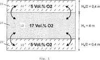
図1は、バッファガス(22、22')と大気(12)を混合する以前の、バッファ室(20、20')および目標エリア(10)を示す概略図である。バッファ空間は、5容積%の酸素量を有するバッファガスを収納している。目標エリアは、基本不活性レベルの17容積%の酸素濃度を有する大気を収納している。バッファ空間(20、20')の高さ(H)は横に示している。
【0028】
図2は、バッファガス(22、22')と大気(12)を混合した後の、図1に示したのと同じ概略図である。高さ、および濃度比によって、式(5)に従って、完全不活性レベルの15容積%の酸素濃度が全域にわたって生じる。これは、火災抑制のために、あるいは火災検知信号の結果、夜間操作の間に生じる。
【0029】
図3は、供給ライン(31)によって相互に接続された幾つかのバッファ空間(20、20’)を備えた建物を示す概略図である。実施例では、建物の個々のエリアは、基本不活性レベルに調整したバッファガスを備えている。個々のバッファ空間(20、20’)は弁またはバルブ(53)を介して供給ライン(31)に接続されている。かくして、火災時には、目標エリア(10)には、他のバッファ空間(20’、20’)からバッファガス(22、22’)が供給され、目標エリアにおいて完全不活性レベルに調整される。その結果、目標エリアの消火活動が速やかに且つ効果的に行われる。
【0030】
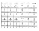
図4は、混合前後の、そこに存在する酸素濃度(K)に基づく、各種容積比(V)およびバッファ空間の高さ(H)および目標エリアをそれぞれ示す表である。バッファ空間および目標エリアにおける各種酸素濃度から始まって、高さおよび容積比において、11から15容積%の間で完全不活性レベルに達する。これによって、使用エリアに存在する可燃材と関連する必要な濃度および容積比が可能になる。
【0031】
図5は、この発明に従って方法を実行する装置の操作図である。バッファ空間(20、20')および目標エリア(10)が図に示されている。バッファ空間および目標エリアは供給ライン(30、30')によって相互に連絡され、換気装置(54、54')および換気用フラップ(52、52')からなる混合ユニット(50、50')が備えられている。この設計では、生成装置(80)がバッファ空間および目標エリアに窒素を供給し、バッファガス(22、22')および大気(12)中の酸素濃度を特定の値に調整する。酸素濃度は酸素測定装置(40、40')によって記録され、信号として制御ユニット(60)に送られる。制御ユニットは信号ラインを経由して生成装置(80)を作動させる。制御ユニット(60)は、他の信号ラインを経由して、生成装置を夜間操作または昼間操作に切り替えるタイマーからなっている。生成装置(80)は、窒素の供給を増加または減少させて、バッファ空間および目標エリアにおいて所望のレベルを確立する。かくして、火災は発生直後から抑制される。更に、火災検知器(70、70')を経由して、混合ユニットを、火災時に混合ユニットを作動させる制御ユニット(62)によって、直接作動させることができる。
【0032】
上述した全ての記載は、単独でまたは組み合わせによって、特に図に示す詳細はこの発明にとって重要な事項であり、当業者はそれらの改良を容易に行うことができる。
【図面の簡単な説明】
【図1】 図1は、バッファガス(22、22')と大気(12)を混合する以前の、バッファ室(20、20')および目標エリア(10)を示す概略図である。
【図2】 図2は、バッファガス(22、22')と大気(12)を混合した後の、図1に示したのと同じ概略図である。
【図3】 図3は、供給ライン(31)によって相互に接続された幾つかのバッファ空間(20、20')を備えた建物を示す概略図である。
【図4】 図4は、混合前後の、そこに存在する酸素濃度(K)に基づく、各種容積比(V)およびバッファ空間の高さ(H)および目標エリアをそれぞれ示す表である。
【図5】 図5は、この発明に従って方法を実行する装置の操作図である。
【符号の説明】
10.目標エリア
12.大気
20、20'.バッファ
22、22'.バッファガス容量
30、30'.供給ライン
31.ガス供給ライン
40、40'.酸素測定装置
50、50'.混合ユニット
52、52'.換気用フラップ
53.弁/バルブ
54、54'.換気装置
60.制御ユニット
62.タイミング装置
70、70'.火災検知器
80.生成装置[0001]
BACKGROUND OF THE INVENTION
The present invention relates to an inactivation method for fire suppression and / or fire extinguishing in a closed space (hereinafter referred to as a target area). The invention further relates to an apparatus for carrying out the method described above with an oxygen measuring device and an oxygen-suppressing gas in the target area.
[0002]
[Prior art]
Fire suppression or extinguishing methods and devices are known in the art. The effect of the so-called inert gas fire extinguishing method is mainly based on the following facts. In other words, when conventional firefighting methods (by water and bubbles), which are occasionally accessed by humans or animals, are applied, the devices in the space can suffer tremendous damage. This can be prevented by reducing the oxygen concentration to an average of about 12% by volume.
[0003]
The area to be applied is an electronic data processing area, an electric control and distribution room, or a storage for storing high quality products. The effect of fire extinguishing is based on the principle of oxygen exclusion. The normal atmosphere consists of 21% oxygen, 78% nitrogen, and 1% other gases. For fire fighting, for example, the concentration of nitrogen in the target area can be further increased by introducing pure nitrogen, resulting in a decrease in oxygen content. It is widely known that a fire extinguishing effect appears when the amount of oxygen is less than 15% by volume. Depending on the material stored in the specific area, it is required to further reduce the above-mentioned 12% by volume or less.
[0004]
In general, gases such as carbon dioxide, nitrogen, inert gases, and mixtures thereof are used as oxygen-suppressing gases, which are usually housed in steel cylinders in specific adjacent areas. In the past, a significant amount of fire extinguishing gas had to be stored in order to meet the target area, particularly open plan offices and warehouses used commercially, with fire extinguishing gas. Since the pressure of the gas cylinder is limited by the ultimate load of available fittings and the volume cannot be increased as desired, a large number of cylinders are required to make the fire extinguishing gas usable Met. Due to this fact and the required gas pipes and fittings, the demands on the final load capacity and scale of the storage area were high. Even if the cylinders were stored underground, considerable structural addition was required to lay the supply line to the target area. In addition, large storage areas increase building and operating costs.
[0005]
Recently, it has been shown that this problem can be solved by reducing the amount of oxygen in the target area to an average basic inertness level of about 17% by volume that is harmless to the organism. By doing so, the amount of fire extinguishing gas required to reach a fully inert level with an oxygen concentration of 15% by volume to suppress or extinguish the fire is reduced. This improves the storage problem described above. However, depending on the load capacity and scale, a structural treatment for the specific facility storing the steel cylinder is required. In particular, in view of the trend toward large-scale facilities, this leads to a significant increase in costs during construction and use.
[0006]
An object of the present invention is to provide an inactivation method capable of storing a fire extinguishing gas necessary for fire extinguishing in a simple and economical manner, usually without relying on specially provided facilities, and for implementing the same To provide an apparatus.
[0007]
DISCLOSURE OF THE INVENTION
The problem is solved by the following inactivation method. That is, in the first step (a), the oxygen suppression gas is introduced into the target area and adjusted to the first basic inert level in which the amount of oxygen is reduced compared to the natural condition. In the second step (b), an oxygen suppression gas is introduced into a closed buffer space that is in communication with the target area via a supply line to generate a buffer gas. Since the amount of oxygen in the buffer gas low, when the buffer gas is mixed with air in the target area, it is possible to reach a complete inactivation levels for fire fighting. In a third step (c), if the time or the need for fire, a buffer gas which is previously stored in the buffer space via a feed line to guide the target area, the air in the target area and a buffer gas The buffer gas is gradually or rapidly introduced into the target area, and the target area is further reduced in oxygen content. The inertness is different from the first basic inert level. Adjust the inert level to an inert level with reduced oxygen levels at or above the level .
[0008]
DETAILED DESCRIPTION OF THE INVENTION
This invention accommodates problematic fire extinguishing gases that must be stored under pressure in special containers such as steel cylinders and require special facilities due to weight and other safety reasons. Proceeded in consideration. On the other hand, considering the dominant concept of the new structure, mainly in the commercial sector, a substantial part of the facility is separated for purposes other than the practical use of the facility by humans and / or animals. However, only a small part of the facility is equipped with facilities such as air conditioning, lighting, and cable chute. Necessary for extinguishing fire without condensing in the target area if there is buffer space by adjusting the basic inertness level with an average oxygen amount of about 17% by volume close to the complete inertness level of 15% by volume or less. It can be equipped with an appropriate amount of fire extinguishing gas.
[0009]
The buffer space described above can be formed in a part of a facility such as an intermediate ceiling, a double floor, a partition, or an adjacent area. The wall of the buffer space may be a solid partition or sheeting. The amount of oxygen in the buffer gas existing in the buffer space, which is adjusted by the first step (a) of the above-described method, is very small. Therefore, the buffer gas is mixed with the atmosphere in the target area to obtain an average of about 17% by volume. After maintaining the basic activity level of the oxygen concentration, the oxygen concentration for fire suppression and / or fire extinguishing is adjusted to a completely inert level of 15% by volume or less throughout the entire area.
[0010]
However, the volume and oxygen concentration ratio between the buffer space and the target area must be monitored. These can be confirmed by the following formula:
Vn: volume of buffer space Vr: volume of target area Vrn: volume of all area and Kn: oxygen concentration of buffer space Kr: oxygen concentration of target area Knr: oxygen concentration of all area
From the basic expression of the volume and concentration ratio with respect to the total buffer space and target area before and after mixing, Vn. Kn + Vr. Vr = Vnr. Krn (1)
Vnr = Vn + Vr (2)
And V = A. H (3)
here,
V: Volume of space A: Floor space of area H: Height of space
Applying equation (2) to equation (1) and determining by Vn / Vr:
Vn / Vr = (Knr-Kr) / (Kn-Knr) (4)
Then applying equation (3) to equation (4)
Hn / Hr = (Knr-Kr) / (Kn-Knr) (5)
[0013]
Thus, equation (5) shows the required height ratio Hn / Hr between the buffer space and the target area, i.e., the oxygen concentration Knr as a fully inert level, when: The basic inertness level Kr of the target area and the oxygen concentration Kn in the buffer space. Conversely, the necessary oxygen concentration is of course determined from the specific ratio Hn / Hr.
[0014]
The advantages of the method described in the dependent claims will now be described.
According to the invention, the advantages of inactivation methods, among extinguishing operation, likewise the amount of oxygen is reduced, the first basic inert level different from the second basic inert level (also referred to as a full inertization level) It can be adjusted. Thus, the method of the present invention is applicable to existing uses of buildings at the maximum. For example, a complex building that is not used or accessed by people / animals at night is changed from a basic inert level with an oxygen concentration of 17% by volume during the daytime to a basic inert level with an oxygen concentration of 15% by volume at night. The oxygen suppression gas is supplied from the buffer space to reach a completely inert level for fire fighting operations where the oxygen concentration is less than 15% by volume, and a fire extinguishing effect is achieved immediately. Of course, the second basic inertness level can be adjusted for nighttime operation as fire suppression means and, if necessary, for fire extinguishing during weekends, holidays or when the building is not in use.
[0015]
Based on the specific amount ratio and concentration ratio of oxygen in both areas, if the atmosphere in the target area is mixed with buffer gas so that the average oxygen concentration is 8 to 17% by volume, the fire is effectively suppressed according to the fire detection signal Or fire extinguisher. This is accomplished as follows. For daytime operation, a basic inactivity level, for example 17% by volume, is first set. The basic inactivity level described above is harmless to creatures that are present on the spot. For night operation, a further reduced basic inactive example bell, for example 15% by volume, is set as the second step. The further reduced basic inertness level to the completely inert level, for example 11% by volume, can be easily reached by quickly supplying the oxygen suppression gas from the buffer gas to the target area. Thus, the fire is effectively suppressed by developing from adjusting the basic inertness level for daytime operation. Oxygen concentration shifts to a basic inert level for night operation, and in the event of a fire, it transitions to a completely inert level where most of the monitored facilities will not burn.
[0016]
Particularly effective is that the amount of oxygen in the buffer volume is 10% by volume or less. This amount of oxygen provides sufficient safety against leakage from the buffer space. This is possible by collecting each, and by mixing the buffer gas and the atmosphere, the basic deactivation level is most effectively transferred to the full deactivation level.
The buffer gas preferably consists of pure inert gas. Thus, an oxygen-suppressing gas for minimizing the amount of oxygen in the target area is possible, which is effective for highly combustible materials in the monitored facility.
[0017]
In a preferred embodiment, if necessary, one or more other areas of buffer gas can be directed to the target area via the supply line. The advantage of this aspect is that when several areas of the facility are each equipped with one buffer, all the buffer inert gas can be used for extinguishing one target area. Thus, in the case specific buffer gas is an amount to adjust the basic inert level, respectively may also be adjusted to full inertization level. As a result, effective fire fighting is possible even in such areas.
[0018]
The problems faced by the invention can also be solved by an apparatus for performing the method described above by means of a closed buffer space connected via a gas supply line adjacent to the target area. The buffer gas is generated in the buffer space by introducing an oxygen suppression gas. Since the amount of oxygen in the buffer gas is very low, a completely inert level for performing a fire fighting operation can be reached by mixing the buffer gas with the atmosphere in the target area (chamber). Via the supply line, the basic inert gas in the target area can be controlled from the buffer space and a rapid complete inertness of the target area can be established.
It is naturally considered to supply several target areas adjacent from the buffer space.
[0019]
Further advantages of the claimed device are described below.
Other embodiments according to the invention are possible. That is, adjusting for the fire extinguishing operation to a second basic inactive level or a completely inactive level, which is different from the first basic inactive level and in which the amount of oxygen is further reduced than the first basic inactive level. Can do. The second basic inert level described above is usually close to a very fully inert level that can be extinguished in a closed space and can be adjusted on weekends, holidays or periods when facilities are not in use. If necessary, a completely inert level for fire extinguishing can be reached quickly by supplying oxygen-suppressing gas from the buffer space.
[0020]
The buffer space is designed as a container, particularly as a tank. In this way, the leakage that occurs when using a structurally special facility for storing buffer gas is eliminated in advance. The container is constructed as follows. That is, it is possible to use a free space in the intermediate ceiling or partition, and the containers can be arranged effectively.
[0021]
In another aspect, each buffer space of a building room is connected to an individual area via a gas supply line. Thus, if necessary, one or more buffer gases can be introduced into the target area via supply lines by buffers in other areas. For this purpose, it is necessary that each building area is provided with one buffer in advance. In this manner, even if the capacity of each buffer gas is large enough to adjust the basic inertness level of the individual areas, it is possible to reach a completely inert level for fire fighting in the target area.
[0022]
Areas where the unique buffer gas volume is large enough to adjust the respective basic inertness level are advantageously connected via valves or valves by supply lines to the buffer spaces of the other areas. Thus, for fire holding, the supply of buffer gas in the other buffer areas to the target area is controlled and readjusted when the fully inert level at the target area is reached. This effectively and quickly extinguishes the fire in the target area.
[0023]
In order to quickly mix the buffer gas with the atmosphere, a mixing unit is provided to effectively mix the atmosphere in the target area with the buffer gas. Thus, in the event of a fire, mixing occurs quickly and reaches a fully inert level in the target area. However, the basic inactivity level in the target area may be controlled from the buffer space. It is preferred to provide a mixing unit with a ventilation flap and a ventilation device arranged in the target area. When the ventilation flap is closed, this simple design provides a large and airtight seal of the buffer space with respect to the target area. When the ventilation flap is fully or partially opened, the target area can be covered under control.
[0024]
A control unit for regulating the amount of oxygen in the target area is effectively provided with a signal transmitter for switching from daytime operation to nighttime operation. With such a control unit, an inactivity level can be applied to the operating state as desired from time to time. The signal transmitter makes the desired switch between daytime and nighttime operation independent of manual operation and does not require personnel for operation.
In accordance with a possible embodiment, the control unit measures the amount of CO or CO2 to monitor atmospheric air conditions and activates a ventilation flap or ventilator to supply fresh air. The advantage of this embodiment is that it does not require an additional device for controlling atmospheric air conditions.
[0025]
The signal transmitter is preferably designed to transmit a timing signal, a burglar alarm signal, or an access management signal. For example, if the timing device is used as a signal transmitter, an automatic transition from daytime to nighttime operation can be preprogrammed. This type of preset can be performed on days when operations are not performed, for example, on weekends when a person is not normally in the facility to be monitored, and adjusts the basic inertness level to less than daytime operations that suppress fire. However, the signal transmitter can be thought of as an access control device, when it is proved to be the identity by a code or a magnetic card, it sends a signal to the control device and sets the inactivity level to be harmless to the organism. To do. When using a burglar alarm signal as a signal transmitter, switching to complete inactivity may be performed if the area can be switched sharply after all people leave the place.
[0026]
With fire detectors, for example, automatic smoke or heat detectors, or portable fire detectors that operate to mix the buffer gas with the atmosphere in the target area for fire fighting operations, fires are reliably detected at any time It is confirmed that the fire can be extinguished. Furthermore, the above-described fire detector can issue a sound and / or visible warning to personnel in the area concerned. At the same time, the fire detector and the fire door can be linked. That is, when the air in the area concerned is operated so as to mix with the buffer gas, the fire door is automatically closed and separated from the other areas.
[0027]
FIG. 1 is a schematic diagram showing a buffer chamber (20, 20 ′) and a target area (10) before mixing the buffer gas (22, 22 ′) and the atmosphere (12). The buffer space contains a buffer gas having an oxygen amount of 5% by volume. The target area contains the atmosphere having an oxygen concentration of 17% by volume of the basic inert level. The height (H) of the buffer space (20, 20 ′) is shown horizontally.
[0028]
FIG. 2 is the same schematic as shown in FIG. 1 after mixing the buffer gas (22, 22 ′) and the atmosphere (12). Depending on the height and concentration ratio, a fully inert level of 15% by volume of oxygen concentration occurs across the entire range according to equation (5). This occurs during night operation for fire suppression or as a result of a fire detection signal.
[0029]
FIG. 3 is a schematic diagram showing a building with several buffer spaces (20, 20 ′) interconnected by a supply line (31). In an embodiment, individual areas of the building are provided with a buffer gas adjusted to a basic inertness level. The individual buffer spaces (20, 20 ′) are connected to the supply line (31) via valves or valves (53). Thus, in the event of a fire, the target area (10) is supplied with the buffer gas (22, 22 ') from the other buffer spaces (20', 20 ') and adjusted to a completely inert level in the target area. As a result, fire extinguishing activities in the target area are quickly and effectively performed.
[0030]
FIG. 4 is a table showing various volume ratios (V), buffer space heights (H), and target areas based on oxygen concentrations (K) existing before and after mixing. Starting from various oxygen concentrations in the buffer space and the target area, a completely inert level is reached between 11 and 15% by volume in height and volume ratio. This allows the necessary concentration and volume ratio associated with the combustible material present in the use area.
[0031]
FIG. 5 is an operational diagram of an apparatus for carrying out the method according to the present invention. The buffer space (20, 20 ′) and the target area (10) are shown in the figure. The buffer space and the target area are interconnected by a supply line (30, 30 ′) and are provided with a mixing unit (50, 50 ′) consisting of a ventilator (54, 54 ′) and a ventilation flap (52, 52 ′). It has been. In this design, the generator (80) supplies nitrogen to the buffer space and target area, and adjusts the oxygen concentrations in the buffer gas (22, 22 ') and atmosphere (12) to specific values. The oxygen concentration is recorded by the oxygen measuring device (40, 40 ') and sent as a signal to the control unit (60). The control unit activates the generator (80) via the signal line. The control unit (60) consists of a timer for switching the generator to night operation or day operation via another signal line. The generator (80) increases or decreases the nitrogen supply to establish the desired level in the buffer space and target area. Thus, the fire is suppressed immediately after the outbreak. Furthermore, via the fire detector (70, 70 '), the mixing unit can be operated directly by a control unit (62) that operates the mixing unit in the event of a fire.
[0032]
All the descriptions above are singly or in combination, and particularly the details shown in the drawings are important matters for the present invention, and those skilled in the art can easily make improvements.
[Brief description of the drawings]
FIG. 1 is a schematic diagram showing a buffer chamber (20, 20 ′) and a target area (10) before mixing the buffer gas (22, 22 ′) and the atmosphere (12).
FIG. 2 is the same schematic as shown in FIG. 1 after mixing the buffer gas (22, 22 ′) and the atmosphere (12).
FIG. 3 is a schematic diagram showing a building with several buffer spaces (20, 20 ′) interconnected by a supply line (31).
FIG. 4 is a table showing various volume ratios (V), buffer space heights (H), and target areas based on oxygen concentrations (K) existing before and after mixing, respectively.
FIG. 5 is an operational diagram of an apparatus for performing the method according to the present invention.
[Explanation of symbols]
10.
Claims (17)
a )酸素抑制ガスを前記目標エリアに導入し、自然条件と比較して酸素量が減少した第1の基本不活性レベルに調整するステップと、
b )前記目標エリア内の大気と混合すると、前記第1の基本不活性レベルよりもさらに酸素量が減少した不活性レベルに到達させるガスであって、供給ラインを経由して前記目標エリアに連絡されている、少なくとも1つの閉鎖されたバッファ空間において、前記酸素抑制ガスによって酸素量の低いバッファガスを生成するステップと、
c )火災発生の際または必要に応じて、前記バッファ空間に予め収納されている前記バッファガスを前記供給ラインを経由して前記目標エリアに誘導して、該目標エリアにおける大気と前記バッファガスとを混合するステップであって、前記バッファガスを、漸次または急速に前記目標エリアに導入し、前記目標エリア内を、さらに酸素量が減少した、前記第1の基本不活性レベルと異なるある不活性レベルまたはそれ以上に酸素量が減少した不活性レベルに調節するステップ
を含むことを特徴とする不活性化方法。 An inactivation method for suppressing and / or extinguishing a fire in a closed space (hereinafter referred to as a target area),
a step of introducing a) oxygen suppressing gas into the target area is adjusted to the first basic inert level oxygen amount is reduced compared to natural conditions,
b ) A gas that, when mixed with the atmosphere in the target area, reaches an inert level in which the amount of oxygen is further reduced from the first basic inert level, and communicates with the target area via a supply line. Generating a low oxygen content buffer gas with the oxygen-suppressing gas in at least one closed buffer space ,
If during or necessary c) fire, said the buffer gas which is previously stored in the buffer space via the supply line guided to the target area, and the buffer gas and the atmosphere in the target area The buffer gas is gradually or rapidly introduced into the target area, the oxygen content in the target area is further reduced, and the inertness is different from the first basic inert level. Adjusting to an inert level with reduced oxygen levels at or above the level
A deactivation method comprising the steps of:
Applications Claiming Priority (3)
| Application Number | Priority Date | Filing Date | Title |
|---|---|---|---|
| DE10101079 | 2001-01-11 | ||
| DE10121550A DE10121550B4 (en) | 2001-01-11 | 2001-05-03 | Inerting process with nitrogen buffer |
| PCT/DE2001/004245 WO2002055155A1 (en) | 2001-01-11 | 2001-11-12 | Inert rendering method with a nitrogen buffer |
Publications (3)
| Publication Number | Publication Date |
|---|---|
| JP2004516910A JP2004516910A (en) | 2004-06-10 |
| JP2004516910A5 JP2004516910A5 (en) | 2007-02-15 |
| JP4105548B2 true JP4105548B2 (en) | 2008-06-25 |
Family
ID=26008212
Family Applications (1)
| Application Number | Title | Priority Date | Filing Date |
|---|---|---|---|
| JP2002555884A Expired - Fee Related JP4105548B2 (en) | 2001-01-11 | 2001-11-12 | Inactivation method with nitrogen buffer |
Country Status (17)
| Country | Link |
|---|---|
| US (1) | US7156184B2 (en) |
| EP (1) | EP1261396B1 (en) |
| JP (1) | JP4105548B2 (en) |
| CN (1) | CN1251775C (en) |
| AT (1) | ATE330673T1 (en) |
| AU (1) | AU2002221560B2 (en) |
| CA (1) | CA2408676C (en) |
| CY (1) | CY1105283T1 (en) |
| CZ (1) | CZ298794B6 (en) |
| DE (1) | DE50110253D1 (en) |
| DK (1) | DK1261396T3 (en) |
| ES (1) | ES2264678T3 (en) |
| NO (1) | NO335357B1 (en) |
| PL (1) | PL195429B1 (en) |
| PT (1) | PT1261396E (en) |
| RU (1) | RU2266767C2 (en) |
| WO (1) | WO2002055155A1 (en) |
Families Citing this family (26)
| Publication number | Priority date | Publication date | Assignee | Title |
|---|---|---|---|---|
| ATE330673T1 (en) | 2001-01-11 | 2006-07-15 | Wagner Alarm Sicherung | INERTIZATION PROCESS WITH NITROGEN BUFFER |
| DE10352437A1 (en) * | 2003-11-10 | 2005-06-16 | Wagner Alarm- Und Sicherungssysteme Gmbh | Device for preventing and extinguishing fires |
| US20050115721A1 (en) | 2003-12-02 | 2005-06-02 | Blau Reed J. | Man-rated fire suppression system |
| US7337856B2 (en) | 2003-12-02 | 2008-03-04 | Alliant Techsystems Inc. | Method and apparatus for suppression of fires |
| ES2340576T3 (en) | 2003-12-29 | 2010-06-07 | Amrona Ag | INERTIZATION PROCEDURE TO EXTINGUISH A FIRE. |
| EP1550481B1 (en) * | 2003-12-29 | 2012-12-19 | Amrona AG | Inerting method for decreasing the risk of a fire |
| JP4679113B2 (en) * | 2004-10-29 | 2011-04-27 | 株式会社竹中工務店 | Low oxygen concentration fire prevention system |
| ES2398958T3 (en) * | 2005-01-21 | 2013-03-22 | Amrona Ag | Inerting procedure for fire prevention |
| WO2007079724A2 (en) * | 2006-01-16 | 2007-07-19 | Peter Fuchs | Fire-fighting method and device by means of inert gas |
| PL1911498T3 (en) * | 2006-10-11 | 2009-07-31 | Amrona Ag | Multi-stage inerting method for preventing and extinguishing fires is enclosed spaces |
| EP1913978B1 (en) * | 2006-10-19 | 2009-05-27 | Amrona AG | Inerting device with nitrogen generator |
| ATE543541T1 (en) * | 2006-12-08 | 2012-02-15 | Amrona Ag | METHOD AND DEVICE FOR THE CONTROLLED SUPPLY OF SUPPLY AIR |
| EP2014336B1 (en) * | 2007-07-13 | 2010-03-10 | Amrona AG | Method and device for fire prevention and/or fire fighting in closed rooms |
| CA2694901C (en) * | 2007-08-01 | 2015-01-27 | Amrona Ag | Device and method for fire-prevention and for extinguishing a fire that has broken out in an enclosed area |
| RU2469759C2 (en) * | 2007-08-01 | 2012-12-20 | Амрона Аг | Inerting method used to reduce inflammation hazard in closed space, and device for implementation of that method |
| CN101559269B (en) * | 2009-03-27 | 2012-01-11 | 西安新竹防灾救生设备有限公司 | Active nitrogen-rich fire-proof device |
| US8672348B2 (en) | 2009-06-04 | 2014-03-18 | Alliant Techsystems Inc. | Gas-generating devices with grain-retention structures and related methods and systems |
| US20110308823A1 (en) * | 2010-06-17 | 2011-12-22 | Dharmendr Len Seebaluck | Programmable controller for a fire prevention system |
| US8939225B2 (en) | 2010-10-07 | 2015-01-27 | Alliant Techsystems Inc. | Inflator-based fire suppression |
| RU2482278C2 (en) * | 2011-03-16 | 2013-05-20 | Государственное общеобразовательное учреждение высшего профессионального образования "Национальный исследовательский Томский политехнический университет" | Method for fire fighting in mines |
| US8967284B2 (en) | 2011-10-06 | 2015-03-03 | Alliant Techsystems Inc. | Liquid-augmented, generated-gas fire suppression systems and related methods |
| US8616128B2 (en) | 2011-10-06 | 2013-12-31 | Alliant Techsystems Inc. | Gas generator |
| GB201200829D0 (en) * | 2012-01-18 | 2012-02-29 | Albertelli Aldino | Fire suppression system |
| EP3011999B1 (en) * | 2014-10-24 | 2017-08-16 | Amrona AG | System and method for reducing the oxygen in a target space |
| US20160206904A1 (en) * | 2015-01-15 | 2016-07-21 | Carrier Corporation | Extended discharge fire protection system and method |
| GB2554857A (en) * | 2016-09-29 | 2018-04-18 | Mexichem Fluor Sa De Cv | A propellant filling apparatus |
Family Cites Families (15)
| Publication number | Priority date | Publication date | Assignee | Title |
|---|---|---|---|---|
| US1839658A (en) * | 1929-10-30 | 1932-01-05 | Gas Fire Extinguisher Corp Du | Method of extinguishing fires |
| US2841227A (en) * | 1955-05-31 | 1958-07-01 | Minimax Ag | Apparatus for extinguishing fires |
| US3486562A (en) * | 1968-03-08 | 1969-12-30 | David K Goodloe | Fire prevention,detection and extinguishing system |
| US4224994A (en) * | 1979-06-21 | 1980-09-30 | Deere & Company | Single control for gas actuated fire extinguishers |
| DE2940601A1 (en) * | 1979-10-06 | 1981-04-09 | Heckler & Koch Gmbh, 7238 Oberndorf | FIRE EXTINGUISHERS |
| US4807706A (en) | 1987-07-31 | 1989-02-28 | Air Products And Chemicals, Inc. | Breathable fire extinguishing gas mixtures |
| RU2074758C1 (en) | 1993-03-16 | 1997-03-10 | Товарищество с ограниченной ответственностью "Меком" | Device for suppression and prevention of fire |
| NL9401480A (en) * | 1994-09-09 | 1996-04-01 | Tech Inspectie En Adviesbureau | Method for extinguishing a fire. |
| JP3719565B2 (en) * | 1997-03-27 | 2005-11-24 | 能美防災株式会社 | Fire extinguishing method and fire extinguishing apparatus |
| RU2118551C1 (en) * | 1997-07-02 | 1998-09-10 | Федеральный центр двойных технологий "Союз" | Fire-extinguishing method (versions), apparatus (versions) and fire-extinguishing system |
| JP3947610B2 (en) * | 1998-02-17 | 2007-07-25 | 能美防災株式会社 | Fire extinguisher |
| US20020040940A1 (en) | 1998-03-18 | 2002-04-11 | Wagner Ernst Werner | Inerting method and apparatus for preventing and extinguishing fires in enclosed spaces |
| DE19811851C2 (en) | 1998-03-18 | 2001-01-04 | Wagner Alarm Sicherung | Inerting procedure for fire prevention and extinguishing in closed rooms |
| US6016874A (en) | 1998-09-22 | 2000-01-25 | Bennett; Joseph Michael | Compact affordable inert gas fire extinguishing system |
| ATE330673T1 (en) | 2001-01-11 | 2006-07-15 | Wagner Alarm Sicherung | INERTIZATION PROCESS WITH NITROGEN BUFFER |
-
2001
- 2001-11-12 AT AT01273102T patent/ATE330673T1/en active
- 2001-11-12 AU AU2002221560A patent/AU2002221560B2/en not_active Ceased
- 2001-11-12 WO PCT/DE2001/004245 patent/WO2002055155A1/en active IP Right Grant
- 2001-11-12 CA CA002408676A patent/CA2408676C/en not_active Expired - Fee Related
- 2001-11-12 US US10/312,240 patent/US7156184B2/en not_active Expired - Fee Related
- 2001-11-12 DE DE50110253T patent/DE50110253D1/en not_active Expired - Lifetime
- 2001-11-12 PL PL01357445A patent/PL195429B1/en unknown
- 2001-11-12 CN CN01809093.1A patent/CN1251775C/en not_active Expired - Fee Related
- 2001-11-12 ES ES01273102T patent/ES2264678T3/en not_active Expired - Lifetime
- 2001-11-12 DK DK01273102T patent/DK1261396T3/en active
- 2001-11-12 RU RU2002132660/12A patent/RU2266767C2/en not_active IP Right Cessation
- 2001-11-12 CZ CZ20031232A patent/CZ298794B6/en not_active IP Right Cessation
- 2001-11-12 PT PT01273102T patent/PT1261396E/en unknown
- 2001-11-12 EP EP01273102A patent/EP1261396B1/en not_active Expired - Lifetime
- 2001-11-12 JP JP2002555884A patent/JP4105548B2/en not_active Expired - Fee Related
-
2003
- 2003-04-24 NO NO20031842A patent/NO335357B1/en not_active IP Right Cessation
-
2006
- 2006-09-18 CY CY20061101329T patent/CY1105283T1/en unknown
Also Published As
| Publication number | Publication date |
|---|---|
| AU2002221560B2 (en) | 2006-09-14 |
| US20030226669A1 (en) | 2003-12-11 |
| CA2408676C (en) | 2009-01-20 |
| CN1427733A (en) | 2003-07-02 |
| RU2002132660A (en) | 2004-03-27 |
| JP2004516910A (en) | 2004-06-10 |
| ATE330673T1 (en) | 2006-07-15 |
| ES2264678T3 (en) | 2007-01-16 |
| US7156184B2 (en) | 2007-01-02 |
| DE50110253D1 (en) | 2006-08-03 |
| CA2408676A1 (en) | 2002-11-14 |
| NO20031842D0 (en) | 2003-04-24 |
| RU2266767C2 (en) | 2005-12-27 |
| EP1261396B1 (en) | 2006-06-21 |
| WO2002055155A1 (en) | 2002-07-18 |
| CY1105283T1 (en) | 2010-03-03 |
| CN1251775C (en) | 2006-04-19 |
| DK1261396T3 (en) | 2006-08-21 |
| NO335357B1 (en) | 2014-12-01 |
| EP1261396A1 (en) | 2002-12-04 |
| PT1261396E (en) | 2006-10-31 |
| NO20031842L (en) | 2003-04-24 |
| CZ20031232A3 (en) | 2003-08-13 |
| PL195429B1 (en) | 2007-09-28 |
| CZ298794B6 (en) | 2008-01-30 |
| PL357445A1 (en) | 2004-07-26 |
Similar Documents
| Publication | Publication Date | Title |
|---|---|---|
| JP4105548B2 (en) | Inactivation method with nitrogen buffer | |
| US6739399B2 (en) | Inerting method and apparatus for preventing and extinguishing fires in enclosed spaces | |
| CA2301628C (en) | Inerting method for preventing and extinguishing fires in enclosed spaces | |
| JP4883184B2 (en) | Method and apparatus for supplying makeup air under control | |
| CA2694901C (en) | Device and method for fire-prevention and for extinguishing a fire that has broken out in an enclosed area | |
| CA2835565C (en) | Inertisation device with nitrogen generator | |
| AU2008281813B2 (en) | Inertization method for reducing the risk of fire in an enclosed area and device for carrying out said method | |
| MX2007008702A (en) | Inertization method for avoiding fires. | |
| JP4554617B2 (en) | Equipment for preventing and extinguishing fire | |
| JP2007516759A (en) | Deactivation method and apparatus for fire fighting | |
| JPH09276428A (en) | Method and system for preventing and distinguishing fire | |
| JP2003102858A (en) | Fire prevention system for closed space | |
| WO2019035142A1 (en) | An advanced fire prevention system and method thereof | |
| US20140027132A1 (en) | Hypoxic Fire Prevention System, Building Provided Therewith and Method Therefor | |
| UA74822C2 (en) | Inert rendering method for preventing and/or extinguishing fires in enclosed spaces and device for carrying out the method | |
| JP2514816B2 (en) | Building with evacuation room | |
| RU2784515C1 (en) | Method for controlling parameters of oxygen and nitrogen content in gas-air environment supplied by ventilation system to increase fire safety and provide meteorological conditions and air purity, and device implementing it | |
| RU98334U1 (en) | ATMOSPHERE INERTIZATION SYSTEM IN A CLOSED PROTECTED SPACE | |
| CN115601906A (en) | Intelligent fire alarm system of building floor | |
| JP2007222534A (en) | Fire extinguishing/preventing device, and fire extinguishing/preventing method | |
| Fukuda et al. | Development and Practical Application of High-efficiency Fire Control System for the Clean Room |
Legal Events
| Date | Code | Title | Description |
|---|---|---|---|
| A131 | Notification of reasons for refusal |
Free format text: JAPANESE INTERMEDIATE CODE: A131 Effective date: 20061017 |
|
| A524 | Written submission of copy of amendment under article 19 pct |
Free format text: JAPANESE INTERMEDIATE CODE: A524 Effective date: 20061222 |
|
| A131 | Notification of reasons for refusal |
Free format text: JAPANESE INTERMEDIATE CODE: A131 Effective date: 20070612 |
|
| A521 | Request for written amendment filed |
Free format text: JAPANESE INTERMEDIATE CODE: A523 Effective date: 20070822 |
|
| A131 | Notification of reasons for refusal |
Free format text: JAPANESE INTERMEDIATE CODE: A131 Effective date: 20080122 |
|
| A521 | Request for written amendment filed |
Free format text: JAPANESE INTERMEDIATE CODE: A523 Effective date: 20080125 |
|
| TRDD | Decision of grant or rejection written | ||
| A01 | Written decision to grant a patent or to grant a registration (utility model) |
Free format text: JAPANESE INTERMEDIATE CODE: A01 Effective date: 20080304 |
|
| A61 | First payment of annual fees (during grant procedure) |
Free format text: JAPANESE INTERMEDIATE CODE: A61 Effective date: 20080327 |
|
| R150 | Certificate of patent or registration of utility model |
Free format text: JAPANESE INTERMEDIATE CODE: R150 |
|
| FPAY | Renewal fee payment (event date is renewal date of database) |
Free format text: PAYMENT UNTIL: 20110404 Year of fee payment: 3 |
|
| FPAY | Renewal fee payment (event date is renewal date of database) |
Free format text: PAYMENT UNTIL: 20120404 Year of fee payment: 4 |
|
| S111 | Request for change of ownership or part of ownership |
Free format text: JAPANESE INTERMEDIATE CODE: R313111 |
|
| FPAY | Renewal fee payment (event date is renewal date of database) |
Free format text: PAYMENT UNTIL: 20120404 Year of fee payment: 4 |
|
| R350 | Written notification of registration of transfer |
Free format text: JAPANESE INTERMEDIATE CODE: R350 |
|
| FPAY | Renewal fee payment (event date is renewal date of database) |
Free format text: PAYMENT UNTIL: 20120404 Year of fee payment: 4 |
|
| FPAY | Renewal fee payment (event date is renewal date of database) |
Free format text: PAYMENT UNTIL: 20130404 Year of fee payment: 5 |
|
| FPAY | Renewal fee payment (event date is renewal date of database) |
Free format text: PAYMENT UNTIL: 20130404 Year of fee payment: 5 |
|
| FPAY | Renewal fee payment (event date is renewal date of database) |
Free format text: PAYMENT UNTIL: 20140404 Year of fee payment: 6 |
|
| R250 | Receipt of annual fees |
Free format text: JAPANESE INTERMEDIATE CODE: R250 |
|
| R250 | Receipt of annual fees |
Free format text: JAPANESE INTERMEDIATE CODE: R250 |
|
| R250 | Receipt of annual fees |
Free format text: JAPANESE INTERMEDIATE CODE: R250 |
|
| LAPS | Cancellation because of no payment of annual fees |