JP4104924B2 - Optical measuring method and apparatus - Google Patents
Optical measuring method and apparatus Download PDFInfo
- Publication number
- JP4104924B2 JP4104924B2 JP2002198074A JP2002198074A JP4104924B2 JP 4104924 B2 JP4104924 B2 JP 4104924B2 JP 2002198074 A JP2002198074 A JP 2002198074A JP 2002198074 A JP2002198074 A JP 2002198074A JP 4104924 B2 JP4104924 B2 JP 4104924B2
- Authority
- JP
- Japan
- Prior art keywords
- light
- light receiving
- transparent
- measurement object
- back surface
- Prior art date
- Legal status (The legal status is an assumption and is not a legal conclusion. Google has not performed a legal analysis and makes no representation as to the accuracy of the status listed.)
- Expired - Lifetime
Links
Images
Classifications
-
- G—PHYSICS
- G01—MEASURING; TESTING
- G01N—INVESTIGATING OR ANALYSING MATERIALS BY DETERMINING THEIR CHEMICAL OR PHYSICAL PROPERTIES
- G01N21/00—Investigating or analysing materials by the use of optical means, i.e. using sub-millimetre waves, infrared, visible or ultraviolet light
- G01N21/84—Systems specially adapted for particular applications
- G01N21/88—Investigating the presence of flaws or contamination
- G01N21/89—Investigating the presence of flaws or contamination in moving material, e.g. running paper or textiles
- G01N21/892—Investigating the presence of flaws or contamination in moving material, e.g. running paper or textiles characterised by the flaw, defect or object feature examined
- G01N21/896—Optical defects in or on transparent materials, e.g. distortion, surface flaws in conveyed flat sheet or rod
-
- G—PHYSICS
- G01—MEASURING; TESTING
- G01B—MEASURING LENGTH, THICKNESS OR SIMILAR LINEAR DIMENSIONS; MEASURING ANGLES; MEASURING AREAS; MEASURING IRREGULARITIES OF SURFACES OR CONTOURS
- G01B11/00—Measuring arrangements characterised by the use of optical techniques
- G01B11/30—Measuring arrangements characterised by the use of optical techniques for measuring roughness or irregularity of surfaces
-
- G—PHYSICS
- G01—MEASURING; TESTING
- G01M—TESTING STATIC OR DYNAMIC BALANCE OF MACHINES OR STRUCTURES; TESTING OF STRUCTURES OR APPARATUS, NOT OTHERWISE PROVIDED FOR
- G01M11/00—Testing of optical apparatus; Testing structures by optical methods not otherwise provided for
-
- G—PHYSICS
- G01—MEASURING; TESTING
- G01N—INVESTIGATING OR ANALYSING MATERIALS BY DETERMINING THEIR CHEMICAL OR PHYSICAL PROPERTIES
- G01N21/00—Investigating or analysing materials by the use of optical means, i.e. using sub-millimetre waves, infrared, visible or ultraviolet light
- G01N21/84—Systems specially adapted for particular applications
- G01N21/88—Investigating the presence of flaws or contamination
- G01N21/95—Investigating the presence of flaws or contamination characterised by the material or shape of the object to be examined
- G01N21/958—Inspecting transparent materials or objects, e.g. windscreens
-
- G—PHYSICS
- G01—MEASURING; TESTING
- G01N—INVESTIGATING OR ANALYSING MATERIALS BY DETERMINING THEIR CHEMICAL OR PHYSICAL PROPERTIES
- G01N21/00—Investigating or analysing materials by the use of optical means, i.e. using sub-millimetre waves, infrared, visible or ultraviolet light
- G01N21/84—Systems specially adapted for particular applications
- G01N21/88—Investigating the presence of flaws or contamination
- G01N21/89—Investigating the presence of flaws or contamination in moving material, e.g. running paper or textiles
- G01N21/8901—Optical details; Scanning details
- G01N2021/8908—Strip illuminator, e.g. light tube
Landscapes
- General Physics & Mathematics (AREA)
- Physics & Mathematics (AREA)
- Chemical & Material Sciences (AREA)
- Analytical Chemistry (AREA)
- Biochemistry (AREA)
- Life Sciences & Earth Sciences (AREA)
- Health & Medical Sciences (AREA)
- General Health & Medical Sciences (AREA)
- Immunology (AREA)
- Pathology (AREA)
- Engineering & Computer Science (AREA)
- Textile Engineering (AREA)
- Investigating Materials By The Use Of Optical Means Adapted For Particular Applications (AREA)
- Length Measuring Devices By Optical Means (AREA)
Description
【0001】
【発明の属する技術分野】
この発明はレーザ光を用いて透明測定対象物の表面および裏面の状態を測定する光学的測定方法およびその装置に関する。
【0002】
【従来の技術】
従来から、液晶表示装置用のガラス基板、フラットパネルディスプレイ装置用の透明膜付き基板などの薄い基板の表面に付着した異物の検査を行うための光学的測定装置が提案されている。
【0003】
たとえば、月間ディスプレイ2001年12月号別冊に記載の発明者らの開発した異物検査装置では、結像検出方式とラインセンサを組み合わせた装置構成を巧みに利用して、裏面に付着した異物を検出する事無く、表面に付着した異物を精度良く検出することを実現している。
【0004】
ガラス基板の裏面に付着した異物からの散乱光は、結像光学系を介してラインセンサのはるか前方で、しかもラインセンサが待ち構える位置からわずかに外れた位置に結像されるように構成されている。このため、裏面に付着した異物はほとんと検出されることが無い。この方式では、光学系の基本的な性質を利用したメカニズムを採用しているため、信頼性が高く、安定して検査できるというものである。
あるいは、特許第2671241号公報に記載された光学的測定装置は、ガラス板に対して第1の入射角度でレーザ光を入射させる第1のレーザ光源と、ガラス板に対して第2の入射角度でレーザ光を入射させる第2のレーザ光源と、各レーザ光に起因する光を集光する集光光学系と、集光された光を受光する受光素子と、受光素子からの信号に基づいて所定の処理を行ってガラス板の被検査面の異物を検出するものである。
【0005】
したがって、例えば、ガラス板の裏面に付着した異物の影響を排除して表面に付着した異物を高精度に検出できると思われる。
【0006】
【発明が解決しようとする課題】
月間ディスプレイ2001年12月号別冊に記載された異物検査装置では、光学系の特性上、裏面に付着した異物も有る大きさ以上になると、わずかながらこの散乱光がラインセンサに入ってきてしまい、裏面に付着した異物を混在して検出してしまう事になる。
【0007】
たとえは、LCD用の1.1mmのガラス基板を表面の1μm以上の異物を検出しようとすると、裏面の20μm以上の異物を同時に検出してしまう事になる。通常のLCD工程内には、20μm程度のごみはほとんと存在しないため、実用上の問題はそれほど大きくないが、裏面に付着した異物を完全に検出しないことが望ましい。
【0008】
さらに当然の事ながら、この方式では、裏面に付着した異物を排除しようとしているだけで、裏面に付着した異物を検出することは出来なかった。
【0009】
特許第2671241号公報に記載された光学的測定装置では、第1のレーザ光源によるレーザ光の照射と第2のレーザ光源によるレーザ光の照射とを互いに独立させて行わなければならないので、スキャン所要時間が2倍になってしまうという不都合がある。
【0010】
また、集光光学系により集光された光を受光素子に導いているので、受光素子の飽和の影響を受けて、表の異物と裏の異物とを区別できなくなってしまう限界が必然的に存在し、この方式でも、ある大きさ以上の裏面に付着した異物を混在して検出してしまう。
【0011】
さらに、ガラス板の表面に付着した異物のみを検出しているだけであるから、ガラス板の裏面に付着した異物を検出することはできない。具体的には、ガラス板の表面の状態を検出できるだけであって、裏面の状態を検出することはできなかった。
【0012】
この発明は上記の問題点に鑑みてなされたものであり、スキャン所要時間を増大させることなく、測定対象面の測定精度を高めることができ、しかも、表面のみならず裏面の状態をも測定することができる光学的測定方法およびその装置を提供することを目的としている。
【0013】
【課題を解決するための手段】
請求項1の光学的測定方法は、支持部材により支持された透明測定対象物の表面に斜め上方から所定角度でラインビームとしての直線状のレーザ光を照射し、透明測定対象物の表面からの散乱光および裏面からの散乱光を、前記透明測定対象物の表面に対して90度の受光角を有し、かつ前記透明測定対象物の厚みよりも小さい焦点深度を有する単一の結像光学系を通過させ、その後に単一のハーフミラーに導き、一方の散乱光を前記単一のハーフミラーを透過させて直線状の受光部を有する、一方の検出器の受光部に結像させ、他方の散乱光を前記ハーフミラーにより反射させて直線状の受光部を有する、他方の検出器の受光部に結像させ、両検出器から出力された信号に基づく所定の処理を行って、選択的に表面に対応する信号、裏面に対応する信号の一方に割り当て、表面に対応する割り当て信号、裏面に対応する割り当て信号をそれぞれ表示する方法である。
【0014】
請求項2の光学的測定装置は、支持部材により支持された透明測定対象物(1)の表面に斜め上方から所定角度でラインビームとしての直線状のレーザ光を照射するレーザ光照射手段(2)と、 透明測定対象物(1)の表面からの散乱光および裏面からの散乱光を結像させる、前記透明測定対象物の表面に対して90度の受光角を有し、かつ前記透明測定対象物の厚みよりも小さい焦点深度を有する単一の結像光学系(3)および該単一の結像光学系(3)の下流側に位置する、単一のハーフミラー(4)と、 前記単一の結像光学系(3)を透過し、かつ前記単一のハーフミラー(4)を透過した一方の散乱光の結像位置、前記単一の結像光学系(3)を透過し、かつ前記単一のハーフミラー(4)により反射された他方の散乱光の結像位置のそれぞれに対応して配置された、直線状の受光部を有する、1対の受光手段(5)(6)と、 両受光手段(5)(6)から出力された信号に基づく所定の処理を行って、選択的に表面に対応する信号、裏面に対応する信号の一方に割り当てる処理手段(7)(8)(9)と、 表面に対応する割り当て信号、裏面に対応する割り当て信号をそれぞれ表示する表示手段とを含むものである。
請求項3の光学的測定装置は、前記透明測定対象物として透明基板を採用するものである。
請求項4の光学的測定装置は、前記処理手段として、一方の受光手段から出力された信号と、他方の受光手段から出力された信号に対して、前記透明基板の表面からの光と裏面からの光との強度比、前記結像光学系の光学的結像特性、焦点深度により定まる値を乗算した値との大小を判定し、判定結果に基づいて選択的に表面に対応する信号、裏面に対応する信号の一方に割り当てるものを採用している。
【0015】
【作用】
請求項1の光学的測定方法であれば、支持部材により支持された透明測定対象物の表面に斜め上方から所定角度でラインビームとしての直線状のレーザ光を照射し、透明測定対象物の表面からの散乱光および裏面からの散乱光を、前記透明測定対象物の表面に対して90度の受光角を有し、かつ前記透明測定対象物の厚みよりも小さい焦点深度を有する単一の結像光学系を通過させ、その後に単一のハーフミラーに導き、一方の散乱光を前記単一のハーフミラーを透過させて直線状の受光部を有する、一方の検出器の受光部に結像させ、他方の散乱光を前記ハーフミラーにより反射させて直線状の受光部を有する、他方の検出器の受光部に結像させ、両検出器から出力された信号に基づく所定の処理を行って、選択的に表面に対応する信号、裏面に対応する信号の一方に割り当て、表面に対応する割り当て信号、裏面に対応する割り当て信号をそれぞれ表示するのであるから、レーザ光によるスキャンを1回だけ行えばよいことに起因してスキャン所要時間を増大させる事なく、透明測定対象物の表面、裏面からの散乱光を結像光学系によって対応する検出器の受光部に結像させることに起因して測定対象面の測定精度を高めることができ、しかも、表面のみならず裏面の状態をも測定することができる。
【0016】
請求項2の光学的測定装置であれば、支持部材により支持された透明測定対象物の表面に対してレーザ光照射手段により斜め上方から所定角度でラインビームとしての直線状のレーザ光を照射し、透明測定対象物の表面からの散乱光および裏面からの散乱光を、前記透明測定対象物の表面に対して90度の受光角を有し、かつ前記透明測定対象物の厚みよりも小さい焦点深度を有する単一の結像光学系を通過させ、その後に単一のハーフミラーに導き、一方の散乱光を前記単一のハーフミラーを透過させて直線状の受光部を有する、一方の検出器の受光部に結像させ、他方の散乱光を前記ハーフミラーにより反射させて直線状の受光部を有する、他方の検出器の受光部に結像させる。そして、処理手段によって、両受光手段から出力された信号に基づく所定の処理を行って、選択的に表面に対応する信号、裏面に対応する信号の一方に割り当て、表示手段によって、表面に対応する割り当て信号、裏面に対応する割り当て信号をそれぞれ表示することができる。
【0017】
したがって、レーザ光によるスキャンを1回だけ行えばよいことに起因してスキャン所要時間を増大させる事なく、透明測定対象物の表面、裏面からの散乱光を結像光学系によって対応する検出器の受光部に結像させることに起因して測定対象面の測定精度を高めることができ、しかも、表面のみならず裏面の状態をも測定することができる。
【0018】
【発明の実施の形態】
以下、添付図面を参照して、この発明の光学的測定方法およびその装置の実施の形態を詳細に説明する。
【0019】
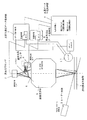
図1はこの発明の光学的測定装置の一実施形態である異物検査装置を示す概略図である。
【0020】
この光学的測定装置は、図示しない支持機構により支持された透明測定対象物(例えば、液晶表示装置用のガラス基板、フラットパネルディスプレイ装置用の透明膜付き基板などの薄い基板)1の表面に対して、所定の入射角でラインビームを照射するレーザ光源2と、照射されたラインビームに起因して透明測定対象物1の表面、裏面から生じる表面散乱光、裏面散乱光を結像させる結像光学系3と、結像位置よりも上流側の所定位置に設けられたハーフミラー4と、ハーフミラー4を透過した表面光の結像位置に受光面が位置するように配置された表面光用センサ5と、ハーフミラー4により反射された裏面光の結像位置に受光面が位置するように配置された裏面光用センサ6と、表面光用センサ5からの出力信号および支持機構の動作情報を入力として透明測定対象物1の表面に対応する2次元の光学的測定データを生成して保持する表面用測定データ保持部7と、裏面光用センサ6からの出力信号および支持機構の動作情報を入力として透明測定対象物1の裏面に対応する2次元の光学的測定データを生成して保持する裏面用測定データ保持部8と、表面用測定データ保持部7に保持されている光学的測定データと裏面用測定データ保持部8に保持されている光学的測定データとを入力として表裏判定処理を行い、透明測定対象物1の表面のみに対応する表面データおよび裏面のみに対応する裏面データを生成して保持する表裏データ生成保持部9と、表面データのみに基づく表示および裏面データのみに基づく表示を行う表示部(図示せず)とを有している。
【0021】
なお、11は透明測定対象物1の位置を示す信号を出力するエンコーダ、12はステージ動作制御部(この実施形態では表面用測定データ保持部7に含まれている)からの制御信号およびエンコーダ11からの信号を入力として支持機構に対する動作指令を出力するステージコントローラである。
【0022】
前記レーザ光源2は、透明測定対象物1の表面に対して、45°以上、90°未満の入射角度、好ましくは80°の入射角度でラインビームを照射するものである。そして、レーザ光源2から出射されるレーザ光は、好ましくはS偏光で波長が400〜1200nm、好ましくは800nmである。また、ラインビームの幅は、表面光用センサ5、裏面光用センサ6の視野幅と同等の幅に設定することが好ましい。
【0023】
前記結像光学系3は焦点深度が透明測定対象物1の厚みよりも小さいものであればよく、焦点深度が透明測定対象物1の厚みの12以下であることが好ましい。また、透明測定対象物1のうねりなどをこの焦点深度以下に納めることが好ましい。
【0024】
前記表面光用センサ5、裏面光用センサ6の配置位置は、透明測定対象物1の屈折率、厚み、レーザ光の入射角度、波長などにより定まる位置オフセット値(ズレ量)を考慮して、透明測定対象物1の表面、裏面が結像される位置と等しい位置に設定される。
【0025】
前記表面用測定データ保持部7、裏面用測定データ保持部8は、表面光用センサ5、裏面光用センサ6からの信号、および透明測定対象物1の移動データを入力とし、かつ該当する場合にはオフセット値を考慮して、透明測定対象物1の表面、裏面にそれぞれ対応する2次元の光学的測定データを生成して保持するものである。
【0026】
前記表裏データ生成保持部9は、前記表面用測定データ保持部7、裏面用測定データ保持部8に保持されている2次元の光学的測定データのうち、同一位置に対応する光学的測定データどうしの関係に基づいて何れの光学的測定データを採用するかを判定し、この判定結果に基づいて透明測定対象物1の表面のみに対応する表面データおよび裏面のみに対応する裏面データを生成して保持するものである。具体的に異物検査装置の場合には、同一位置に対応させて表面用測定データ保持部7に保持されている光学的測定データをA、裏面用測定データ保持部8に保持されている光学的測定データをBとした場合に、取り扱うA、Bの出力信号は双方とも、この時点では不明だが表面か裏面かどちらかに付着した異物からの散乱光強度信号になる。基本的に異物が大きくなれば散乱光強度も大きくなる特性がある。結像光学系と直線状の受光部すなわちラインセンサを用いているので、
この出力信号をその異物の像の総輝度信号とすると、異物の大きさの増加に伴うこの出力信号の増加は、当初はかなり急峻である(像の大きさの変化による影響だけでなく、輝度の変化による影響も大きい)また、散乱光強度が増加に伴って輝度が飽和して、輝度の変化による影響がほとんどなくなった後は、像の大ききの影響を受けて出力信号が緩やかに増加する。従って、出力信号の飽和を生じさせること無く、異物の大きさに見合った出力信号を得ることができる。
【0027】
さらには、このA、Bそれそれの信号を比較して直線状の受光部すなわちラインセンサを用いているので、A>kBならば透明測定対象物1の表面のみに対応する表面データすなわち表面に付着した異物のデータとし、逆に、A≦kBならば透明測定対象物1の裏面のみに対応する裏面データすなわち裏面に付着した異物のデータとする。なお、kは、透明測定対象物1の表面からの光と裏面からの光との強度比や結像光学系の光学的結像特性、焦点深度等により求まる値である。例えば、レーザ光としてS偏光を採用し、入射角度を80°に設定した場合には、裏面からの光強度が表面からの光強度の約1/1になる。これに光学的特性をかね合わせるとkはおよそ2よりも大きな値になる。
【0028】
さらに、前述の出力信号の増加が緩やかになる前後で、この判定式を使い分けることで、より精度の高い判定を実施することができる。すなわち、この時判定式はより複雑な非線形の判定式になる。
【0029】
上記の構成の光学的測定装置の作用は次のとおりである。
【0030】
レーザ光源2から透明測定対象物1の表面に所定の入射角度でラインビームを照射すれば、このラインビームは、スネルの法則に基づく屈折を行って透明測定対象物1の内部に侵入し、裏面から出射する。したがって、ラインビームの透明測定対象物1の表面への照射位置と裏面からの出射位置とは、結像光学系3の光軸を基準として互いに異なり、理想的には、透明測定対象物1の表面への照射位置からの光(散乱光など)の結像位置に配置されたセンサは透明測定対象物1の裏面の出射位置からの光(散乱光など)には不感となる(この光は透明測定対象物1の裏面への照射位置からの光の結像位置に配置されたセンサにより受光される)。また、透明測定対象物1の表面への照射位置と正対する裏面にはラインビームが照射されないので、この部分もセンサには影響を及ぼさないことになる。
【0031】
しかし、実際には、レーザー光の性質上、透明測定対象物1の表面への照射位置と正対する裏面にもわずかな光が照射されるので、センサに影響を及ぼす可能性があり、光学的測定誤差をもたらす原因となる。
【0032】
この実施形態はこのような実状を考慮したものであり、以下の処理を行うことにより、光学的測定誤差を大幅に抑制することができる。
【0033】
さらに説明する。
【0034】
レーザ光源2からのラインビームにより透明測定対象物1をスキャンすれば、透明測定対象物1のラインビーム入射位置からの光が結像光学系3により、かつハーフミラー4を通して、表面光用センサ5の受光面に結像される。また、光量は大幅に減少するものの、ラインビーム入射位置に正対する裏面からの光が結像光学系3により、かつハーフミラー4を通して受光されるが、焦点深度が透明測定対象物1の厚みよりも小さいので、ピンボケ状態となる。
【0035】
また、前記ラインビームは、スネルの法則にしたがって透明測定対象物1の裏面に導かれ、そのまま出射される。したがって、ラインビーム入射位置に正対する裏面位置と、ラインビームが導かれる裏面位置とは互いに異なる。この結果、ラインビームが導かれる裏面位置からの光が結像光学系3により、かつハーフミラー4により反射されて、裏面光用センサ6の受光面に結像される。
【0036】
さて、測定内容を異物検査とした時、これらの場合において、ラインビームの影響を受ける場所に異物が全く存在していなければ散乱光などの強度が著しく低いので、表面光用センサ5、裏面光用センサ6からは異物が存在していないことを示す信号が出力される。
【0037】
逆に、ラインビームの影響を受ける場所に異物が存在していれば散乱光などの強度が高くなるので、表面光用センサ5、裏面光用センサ6からは異物が存在していることを示す信号が出力される。
【0038】
ここで、表面光用センサ5、裏面光用センサ6は、異物の大きさの増加に伴って出力信号が増加する。そして、出力信号の増加は、当初はかなり急峻である(像の大きさの変化による影響よりも輝度の変化による影響が大きい)。また、輝度の変化による影響が殆どなくなった後は、像の大きさの変化による影響を受けて出力信号が緩やかに増加する。したがって、出力信号の飽和を生じさせることなく、異物の大きさに見合った出力信号を得ることができる。この結果、異物の存在とその大きさ判定を良好にすることができる。
【0039】
そして、表面光用センサ5、裏面光用センサ6からの信号、および透明測定対象物1の移動データを入力とし、かつ該当する場合には位置オフセット値を考慮して、前記表面用測定データ保持部7、裏面用測定データ保持部8は、透明測定対象物1の表面、裏面にそれぞれ対応する2次元の光学的測定データを生成して保持する。したがって、表面用測定データ保持部7、裏面用測定データ保持部8には、同じ位置に対応する表面用測定データ、裏面用測定データが保持される。
【0040】
その後は、表裏データ生成保持部9において、表面用測定データ保持部7、裏面用測定データ保持部8に保持されている同じ位置に対応する表面用測定データ、裏面用測定データを比較して何れの光学的測定データを採用するかを判定し、この判定結果に基づいて透明測定対象物1の表面のみに対応する表面データおよび裏面のみに対応する裏面データを生成して保持する。
【0041】
そして、表示部10によって、表面データのみに基づく表示および裏面データのみに基づく表示を行うことができる。
【0042】
異物検査装置の場合は表面データから表面に付着する異物の有無、位置、大きさを得ることができ、裏面データからは裏面に付着する異物の有無、位置、大ききを得ることができる。
【0043】
したがって、これらの表示に基づいて、透明測定対象物1の表面のみならず、裏面に付着した異物の有無、異物の密度などを簡単に、かつ正確に把握することができる。また、例えば、透明測定対象物1の洗浄の前後に上記の一連の処理を行うことによって、洗浄の効果を確認することができる。
【0044】
また、レーザ光源2により1回のスキャンを行うだけで透明測定対象物1の表面のみに対応する表面データおよび裏面のみに対応する裏面データを得ることができるので、所要時間を短縮することができる。
【0045】
【発明の効果】
この発明は、レーザ光によるスキャンを1回だけ行えばよいことに起因してスキャン所要時間を増大することなく、透明測定対象物の表面、裏面からの散乱光を結像光学系によって対応する検出器の受光部に結像させることに起因して被検出面の異物検出精度を高めることができ、しかも、表面のみならず裏面の状態をも検出することができるという特有の効果を奏する。
【図面の簡単な説明】
【図1】この発明の光学的測定装置の一実施形態を示す概略図である。
【符号の説明】
1 透明測定対象物 2 レーザ光源
3 結像光学系 5 表面光用センサ
6 裏面光用センサ 7 表面用測定データ保持部
8 裏面用測定データ保持部 9 表裏データ生成保持部
10 表示部[0001]
BACKGROUND OF THE INVENTION
The present invention relates to an optical measurement method and apparatus for measuring the state of the front and back surfaces of a transparent measurement object using laser light.
[0002]
[Prior art]
2. Description of the Related Art Conventionally, there has been proposed an optical measuring device for inspecting foreign matters adhering to the surface of a thin substrate such as a glass substrate for a liquid crystal display device or a transparent film-coated substrate for a flat panel display device.
[0003]
For example, in the foreign substance inspection apparatus developed by the inventors described in the December 2001 issue of the monthly display, the foreign substance attached to the back surface is detected by skillfully utilizing the apparatus configuration that combines the imaging detection method and the line sensor. It is possible to detect the foreign matter adhering to the surface with high accuracy.
[0004]
Scattered light from foreign matter adhering to the back surface of the glass substrate is imaged in front of the line sensor via the imaging optical system and at a position slightly off the position where the line sensor is waiting. Yes. For this reason, the foreign material adhering to the back surface is hardly detected. This method employs a mechanism that utilizes the basic properties of the optical system, so it is highly reliable and can be inspected stably.
Alternatively, the optical measuring device described in Japanese Patent No. 2671241 includes a first laser light source that makes laser light incident on the glass plate at a first incident angle, and a second incident angle relative to the glass plate. Based on the second laser light source that makes the laser light incident on, a condensing optical system that condenses the light resulting from each laser light, a light receiving element that receives the collected light, and a signal from the light receiving element A predetermined process is performed to detect foreign matter on the surface to be inspected of the glass plate.
[0005]
Therefore, for example, it is considered that the foreign matter attached to the surface can be detected with high accuracy by eliminating the influence of the foreign matter attached to the back surface of the glass plate.
[0006]
[Problems to be solved by the invention]
In the foreign matter inspection apparatus described in the December 2001 issue of the monthly display, when the size of the foreign matter attached to the back surface exceeds the size of the foreign matter, the scattered light slightly enters the line sensor. The foreign matter adhering to the back side will be mixed and detected.
[0007]
For example, if an attempt is made to detect foreign matter of 1 μm or more on the front surface of a 1.1 mm glass substrate for LCD, foreign matter of 20 μm or more on the back surface will be detected at the same time. Since there is almost no 20 μm dust in the normal LCD process, the practical problem is not so great, but it is desirable not to completely detect foreign matter adhering to the back surface.
[0008]
Further, as a matter of course, in this method, it was not possible to detect the foreign matter attached to the back surface only by trying to remove the foreign matter attached to the back surface.
[0009]
In the optical measuring device described in Japanese Patent No. 2671241, the laser beam irradiation by the first laser light source and the laser beam irradiation by the second laser light source must be performed independently of each other, and therefore scanning is required. There is an inconvenience that the time is doubled.
[0010]
In addition, since the light condensed by the condensing optical system is guided to the light receiving element, there is inevitably a limit that makes it impossible to distinguish the foreign substance on the front side from the foreign substance on the back due to the saturation of the light receiving element. Even in this method, foreign matter adhering to the back surface of a certain size or more is mixedly detected.
[0011]
Furthermore, since only foreign matter adhering to the surface of the glass plate is detected, foreign matter adhering to the back surface of the glass plate cannot be detected. Specifically, it was only possible to detect the state of the front surface of the glass plate, but not the state of the back surface.
[0012]
The present invention has been made in view of the above problems, and can increase the measurement accuracy of the measurement target surface without increasing the time required for scanning, and can measure not only the surface but also the state of the back surface. It is an object of the present invention to provide an optical measurement method and an apparatus for the same.
[0013]
[Means for Solving the Problems]
The optical measurement method according to
[0014]
The optical measuring apparatus according to claim 2 is a laser beam irradiation means (2) for irradiating the surface of the transparent measurement object (1) supported by the support member with a linear laser beam as a line beam at a predetermined angle from obliquely above. And a light receiving angle of 90 degrees with respect to the surface of the transparent measurement object, which forms an image of the scattered light from the surface of the transparent measurement object (1) and the scattered light from the back surface, and the transparent measurement A single imaging optical system (3) having a depth of focus smaller than the thickness of the object and a single half mirror (4) located downstream of the single imaging optical system (3) ; Imaging position of one scattered light that has passed through the single imaging optical system (3) and has passed through the single half mirror (4), and transmitted through the single imaging optical system (3) And the imaging position of the other scattered light reflected by the single half mirror (4) A pair of light receiving means (5) and (6) each having a linear light receiving portion arranged corresponding to each of the light receiving means and a predetermined process based on signals output from both light receiving means (5) and (6) And processing means (7) (8) (9) for selectively assigning to one of the signal corresponding to the front surface and the signal corresponding to the back surface, and the allocation signal corresponding to the front surface and the allocation signal corresponding to the back surface, respectively. Display means for displaying.
The optical measuring apparatus according to
The optical measurement apparatus according to claim 4 is configured such that, as the processing unit, a signal output from one light receiving unit and a signal output from the other light receiving unit are transmitted from the light and the back surface of the transparent substrate. A signal corresponding to the surface selectively on the basis of the determination result, and a back surface of the image forming optical system, the optical imaging characteristics of the imaging optical system, and the value obtained by multiplying the value determined by the depth of focus. The signal assigned to one of the signals corresponding to is adopted.
[0015]
[Action]
According to the optical measurement method of
[0016]
According to the optical measuring apparatus of claim 2, the surface of the transparent measurement object supported by the support member is irradiated with a linear laser beam as a line beam at a predetermined angle from a diagonally upper direction by a laser beam irradiation means. the scattered light from the scattered light and the back from the surface of the transparent measurement object, having a light receiving angle of 90 degrees with respect to the surface of the transparent measurement object, and smaller focal than the thickness of the transparent measurement object One detection having a linear light-receiving section through a single imaging optical system having a depth, then guided to a single half mirror, and passing one scattered light through the single half mirror An image is formed on the light receiving portion of the detector, and the other scattered light is reflected by the half mirror to form an image on the light receiving portion of the other detector having a linear light receiving portion . Then, the processing means performs a predetermined process based on the signals output from both light receiving means, and selectively assigns one of the signal corresponding to the front surface and the signal corresponding to the back surface, and corresponds to the front surface by the display means. The assignment signal and the assignment signal corresponding to the back surface can be displayed respectively.
[0017]
Therefore, the scattered light from the front and back surfaces of the transparent measurement object can be detected by the imaging optical system without increasing the time required for scanning due to the fact that the scanning with the laser light needs to be performed only once. It is possible to improve the measurement accuracy of the measurement target surface due to the image formation on the light receiving unit, and it is possible to measure not only the front surface but also the back surface state.
[0018]
DETAILED DESCRIPTION OF THE INVENTION
Embodiments of an optical measurement method and apparatus according to the present invention will be described below in detail with reference to the accompanying drawings.
[0019]
FIG. 1 is a schematic view showing a foreign substance inspection apparatus which is an embodiment of the optical measurement apparatus of the present invention.
[0020]
This optical measuring device is applied to the surface of a transparent measuring object (for example, a thin substrate such as a glass substrate for a liquid crystal display device or a substrate with a transparent film for a flat panel display device) 1 supported by a support mechanism (not shown). Then, a laser light source 2 that irradiates a line beam at a predetermined incident angle, and an image that forms an image of the surface scattered light and the back scattered light generated from the front and back surfaces of the
[0021]
Reference numeral 11 denotes an encoder that outputs a signal indicating the position of the
[0022]
The laser light source 2 irradiates the surface of the
[0023]
The imaging
[0024]
The arrangement positions of the front surface light sensor 5 and the back
[0025]
The front-side measurement data holding unit 7 and the back-side measurement
[0026]
The front / back data generation / holding unit 9 includes optical measurement data corresponding to the same position among the two-dimensional optical measurement data held in the front-side measurement data holding unit 7 and the back-side measurement
If this output signal is the total luminance signal of the image of the foreign object, the increase in the output signal accompanying the increase in the size of the foreign object is initially quite steep (not only the influence of the change in the image size but also the luminance In addition, after the intensity of the scattered light is saturated and the influence of the change in brightness almost disappears, the output signal gradually increases due to the influence of the image size. To do. Therefore, an output signal commensurate with the size of the foreign matter can be obtained without causing saturation of the output signal.
[0027]
Furthermore, since the linear light receiving part, that is, the line sensor, is used by comparing the signals of A and B, if A> kB, the surface data corresponding to only the surface of the
[0028]
Furthermore, it is possible to carry out a more accurate determination by properly using this determination formula before and after the increase in the output signal becomes moderate. That is, at this time, the determination formula becomes a more complicated nonlinear determination formula.
[0029]
The operation of the optical measuring apparatus having the above-described configuration is as follows.
[0030]
When a line beam is irradiated from the laser light source 2 onto the surface of the
[0031]
However, in actuality, because of the nature of the laser light, a slight amount of light is irradiated on the back surface directly opposite to the irradiation position on the surface of the
[0032]
This embodiment considers such an actual situation, and optical measurement errors can be significantly suppressed by performing the following processing.
[0033]
Further explanation will be given.
[0034]
When the
[0035]
The line beam is guided to the back surface of the
[0036]
Now, when the measurement content is a foreign matter inspection, in these cases, if there is no foreign matter at the place affected by the line beam, the intensity of scattered light or the like is extremely low. A signal indicating that no foreign matter is present is output from the
[0037]
On the other hand, since the intensity of scattered light or the like is increased if a foreign object is present in a place affected by the line beam, a signal indicating that a foreign object is present from the front surface light sensor 5 and the rear
[0038]
Here, the output signal of the front light sensor 5 and the back
[0039]
The surface measurement data holding unit receives the signals from the front surface light sensor 5 and the back
[0040]
Thereafter, the front / back data generation / holding unit 9 compares the front-side measurement data and the back-side measurement data corresponding to the same position held in the front-side measurement data holding unit 7 and the back-side measurement
[0041]
The display unit 10 can perform display based only on the front surface data and display based only on the back surface data.
[0042]
In the case of a foreign substance inspection apparatus, the presence / absence, position and size of a foreign substance adhering to the surface can be obtained from the surface data, and the presence / absence, position and size of the foreign substance adhering to the back side can be obtained from the back data.
[0043]
Therefore, based on these displays, it is possible to easily and accurately grasp the presence / absence of foreign matter attached to the rear surface as well as the surface of the
[0044]
Further, the surface time corresponding to only the front surface of the
[0045]
【The invention's effect】
According to the present invention, it is possible to detect scattered light from the front and back surfaces of a transparent measurement object by using an imaging optical system without increasing the time required for scanning because scanning with a laser beam needs to be performed only once. Due to the image formation on the light receiving part of the detector, the foreign matter detection accuracy of the detection surface can be improved, and the state of the back surface as well as the front surface can be detected.
[Brief description of the drawings]
FIG. 1 is a schematic view showing one embodiment of an optical measuring apparatus of the present invention.
[Explanation of symbols]
DESCRIPTION OF
Claims (4)
Priority Applications (5)
| Application Number | Priority Date | Filing Date | Title |
|---|---|---|---|
| JP2002198074A JP4104924B2 (en) | 2002-07-08 | 2002-07-08 | Optical measuring method and apparatus |
| KR1020057000344A KR100876257B1 (en) | 2002-07-08 | 2003-07-08 | Optical measuring method and device therefor |
| CNB038161745A CN100570342C (en) | 2002-07-08 | 2003-07-08 | Method of optically measuring and device thereof |
| PCT/JP2003/008675 WO2004005902A1 (en) | 2002-07-08 | 2003-07-08 | Optical measuring method and device therefor |
| TW092118645A TW200409912A (en) | 2002-07-08 | 2003-07-08 | Optical measuring method and device therefor |
Applications Claiming Priority (1)
| Application Number | Priority Date | Filing Date | Title |
|---|---|---|---|
| JP2002198074A JP4104924B2 (en) | 2002-07-08 | 2002-07-08 | Optical measuring method and apparatus |
Publications (2)
| Publication Number | Publication Date |
|---|---|
| JP2004037400A JP2004037400A (en) | 2004-02-05 |
| JP4104924B2 true JP4104924B2 (en) | 2008-06-18 |
Family
ID=30112417
Family Applications (1)
| Application Number | Title | Priority Date | Filing Date |
|---|---|---|---|
| JP2002198074A Expired - Lifetime JP4104924B2 (en) | 2002-07-08 | 2002-07-08 | Optical measuring method and apparatus |
Country Status (5)
| Country | Link |
|---|---|
| JP (1) | JP4104924B2 (en) |
| KR (1) | KR100876257B1 (en) |
| CN (1) | CN100570342C (en) |
| TW (1) | TW200409912A (en) |
| WO (1) | WO2004005902A1 (en) |
Families Citing this family (15)
| Publication number | Priority date | Publication date | Assignee | Title |
|---|---|---|---|---|
| US7200190B2 (en) * | 2003-06-30 | 2007-04-03 | Motorola, Inc. | Unbiased signal to interference ratio in wireless communications devices and methods therefor |
| JP4417205B2 (en) * | 2004-08-27 | 2010-02-17 | 大日本スクリーン製造株式会社 | Substrate processing equipment |
| JP5082552B2 (en) * | 2007-04-05 | 2012-11-28 | コニカミノルタホールディングス株式会社 | Optical measuring apparatus and optical measuring method |
| KR101209857B1 (en) * | 2009-02-20 | 2012-12-10 | 삼성코닝정밀소재 주식회사 | Detection apparatus for particle on the glass and detection method using the same |
| US7929129B2 (en) | 2009-05-22 | 2011-04-19 | Corning Incorporated | Inspection systems for glass sheets |
| TWI485392B (en) * | 2010-02-08 | 2015-05-21 | Ygk Corp | Foreign body inspection device and inspection method |
| KR101685703B1 (en) * | 2010-02-25 | 2016-12-12 | 가부시끼가이샤 야마나시 기쥬쯔 고오보오 | Alien substance inspection apparatus and inspection method |
| DE102011103003A1 (en) * | 2011-05-24 | 2012-11-29 | Lufthansa Technik Ag | Method and device for crack inspection of an aircraft or gas turbine component |
| JP2013140061A (en) * | 2012-01-02 | 2013-07-18 | Yamanashi Gijutsu Kobo:Kk | Method for detecting foreign substance on front and back sides of transparent flat substrate, and foreign substance inspection device using the method |
| KR20150056713A (en) | 2013-11-15 | 2015-05-27 | 삼성전자주식회사 | Non-destructive inspection system for display panel and method, and non-destructive inspection apparatus therefor |
| EP3158284B1 (en) * | 2014-06-17 | 2022-03-16 | Heraeus Quartz North America LLC | Apparatus and method for heating and measuring of transparent cylindrical articles |
| KR102537558B1 (en) * | 2016-11-02 | 2023-05-26 | 코닝 인코포레이티드 | Method and apparatus for inspecting defects on a transparent substrate |
| JP2018128326A (en) * | 2017-02-07 | 2018-08-16 | 大塚電子株式会社 | Optical spectrum measuring device and method of measuring optical spectrum |
| CN107764841B (en) * | 2017-11-17 | 2024-03-01 | 仝人智能科技(江苏)有限公司 | Device and method for detecting and distinguishing defects of upper surface and lower surface of transparent glass cover plate |
| KR102580487B1 (en) * | 2018-06-18 | 2023-09-21 | 주식회사 케이씨텍 | Pad monitoring apparatus and pad monotirng system, pad monitoring method |
Family Cites Families (7)
| Publication number | Priority date | Publication date | Assignee | Title |
|---|---|---|---|---|
| JPS52130381A (en) * | 1976-04-26 | 1977-11-01 | Hitachi Ltd | Device for detecting faulty part on plate surface |
| JPH06281418A (en) * | 1993-03-24 | 1994-10-07 | Asahi Glass Co Ltd | Optical thickness measuring method of plate-shaped transparent body having ruggedness |
| JP3480176B2 (en) * | 1996-03-18 | 2003-12-15 | 日立電子エンジニアリング株式会社 | Glass substrate front / back defect identification method |
| JPH1048144A (en) * | 1996-07-31 | 1998-02-20 | Dainippon Printing Co Ltd | Glass substrate inspecting instrument |
| JP2000074849A (en) * | 1998-08-31 | 2000-03-14 | Toshiba Corp | Foreign matter detecting method and device |
| JP2001208702A (en) * | 2000-01-31 | 2001-08-03 | Nippon Sheet Glass Co Ltd | Method and apparatus for inspecting defects |
| JP4599507B2 (en) * | 2000-08-23 | 2010-12-15 | 旭硝子株式会社 | Glass plate shape measuring method and shape measuring apparatus |
-
2002
- 2002-07-08 JP JP2002198074A patent/JP4104924B2/en not_active Expired - Lifetime
-
2003
- 2003-07-08 KR KR1020057000344A patent/KR100876257B1/en active IP Right Grant
- 2003-07-08 TW TW092118645A patent/TW200409912A/en not_active IP Right Cessation
- 2003-07-08 CN CNB038161745A patent/CN100570342C/en not_active Expired - Lifetime
- 2003-07-08 WO PCT/JP2003/008675 patent/WO2004005902A1/en active Application Filing
Also Published As
| Publication number | Publication date |
|---|---|
| WO2004005902A1 (en) | 2004-01-15 |
| TW200409912A (en) | 2004-06-16 |
| CN100570342C (en) | 2009-12-16 |
| TWI320099B (en) | 2010-02-01 |
| KR100876257B1 (en) | 2008-12-26 |
| KR20050035243A (en) | 2005-04-15 |
| JP2004037400A (en) | 2004-02-05 |
| CN1666100A (en) | 2005-09-07 |
Similar Documents
| Publication | Publication Date | Title |
|---|---|---|
| JP4104924B2 (en) | Optical measuring method and apparatus | |
| TWI285737B (en) | Inspection of transparent substrates for defects | |
| JPH10160683A (en) | Foreign object inspection method and device | |
| JPH0552762A (en) | Detecting apparatus of foreign matter of glass plate | |
| JPH03267745A (en) | Surface property detecting method | |
| JP2010112803A (en) | Substrate inspecting apparatus and photodetector | |
| JP2012164801A (en) | Inspection apparatus and inspection method | |
| JP5596925B2 (en) | Foreign object inspection apparatus and inspection method | |
| JPH11173946A (en) | Optical characteristic measuring apparatus | |
| JP2010271133A (en) | Optical scanning type plane inspection device | |
| JP2013140061A (en) | Method for detecting foreign substance on front and back sides of transparent flat substrate, and foreign substance inspection device using the method | |
| JP3860202B2 (en) | Transparency sheet defect inspection system | |
| JP3495797B2 (en) | Optical constant measuring method and device | |
| JPH07167793A (en) | Phase difference semiconductor inspection device and its production method | |
| JP3168480B2 (en) | Foreign matter inspection method and foreign matter inspection device | |
| JP2001272355A (en) | Foreign matter inspecting apparatus | |
| JP4358955B2 (en) | Foreign matter inspection device | |
| JP2001264259A (en) | Sheet inspecting device | |
| JPH03115844A (en) | Detection of surface defect | |
| TW201128182A (en) | Foreign object inspection device and method | |
| JP3877875B2 (en) | X-ray sensor and X-ray detection method | |
| JPH09218162A (en) | Surface defect inspection device | |
| JPH10142489A (en) | Method and device for focus detection | |
| JPH10293103A (en) | Method and equipment for optical measurement and optical measuring equipment for patterned substrate | |
| JPS6316232A (en) | Measuring method for diameter of laser beam |
Legal Events
| Date | Code | Title | Description |
|---|---|---|---|
| A621 | Written request for application examination |
Free format text: JAPANESE INTERMEDIATE CODE: A621 Effective date: 20050701 |
|
| A131 | Notification of reasons for refusal |
Free format text: JAPANESE INTERMEDIATE CODE: A131 Effective date: 20061204 |
|
| A521 | Request for written amendment filed |
Free format text: JAPANESE INTERMEDIATE CODE: A523 Effective date: 20070126 |
|
| A521 | Request for written amendment filed |
Free format text: JAPANESE INTERMEDIATE CODE: A523 Effective date: 20070125 |
|
| A521 | Request for written amendment filed |
Free format text: JAPANESE INTERMEDIATE CODE: A523 Effective date: 20070201 |
|
| A131 | Notification of reasons for refusal |
Free format text: JAPANESE INTERMEDIATE CODE: A131 Effective date: 20070702 |
|
| A521 | Request for written amendment filed |
Free format text: JAPANESE INTERMEDIATE CODE: A523 Effective date: 20070831 |
|
| A131 | Notification of reasons for refusal |
Free format text: JAPANESE INTERMEDIATE CODE: A131 Effective date: 20071102 |
|
| A521 | Request for written amendment filed |
Free format text: JAPANESE INTERMEDIATE CODE: A523 Effective date: 20071228 |
|
| TRDD | Decision of grant or rejection written | ||
| A01 | Written decision to grant a patent or to grant a registration (utility model) |
Free format text: JAPANESE INTERMEDIATE CODE: A01 Effective date: 20080303 |
|
| A61 | First payment of annual fees (during grant procedure) |
Free format text: JAPANESE INTERMEDIATE CODE: A61 Effective date: 20080326 |
|
| R150 | Certificate of patent or registration of utility model |
Ref document number: 4104924 Country of ref document: JP Free format text: JAPANESE INTERMEDIATE CODE: R150 Free format text: JAPANESE INTERMEDIATE CODE: R150 |
|
| FPAY | Renewal fee payment (event date is renewal date of database) |
Free format text: PAYMENT UNTIL: 20110404 Year of fee payment: 3 |
|
| FPAY | Renewal fee payment (event date is renewal date of database) |
Free format text: PAYMENT UNTIL: 20110404 Year of fee payment: 3 |
|
| R250 | Receipt of annual fees |
Free format text: JAPANESE INTERMEDIATE CODE: R250 |
|
| FPAY | Renewal fee payment (event date is renewal date of database) |
Free format text: PAYMENT UNTIL: 20120404 Year of fee payment: 4 |
|
| FPAY | Renewal fee payment (event date is renewal date of database) |
Free format text: PAYMENT UNTIL: 20130404 Year of fee payment: 5 |
|
| R250 | Receipt of annual fees |
Free format text: JAPANESE INTERMEDIATE CODE: R250 |
|
| FPAY | Renewal fee payment (event date is renewal date of database) |
Free format text: PAYMENT UNTIL: 20140404 Year of fee payment: 6 |
|
| R250 | Receipt of annual fees |
Free format text: JAPANESE INTERMEDIATE CODE: R250 |
|
| R250 | Receipt of annual fees |
Free format text: JAPANESE INTERMEDIATE CODE: R250 |
|
| R250 | Receipt of annual fees |
Free format text: JAPANESE INTERMEDIATE CODE: R250 |
|
| R250 | Receipt of annual fees |
Free format text: JAPANESE INTERMEDIATE CODE: R250 |
|
| R250 | Receipt of annual fees |
Free format text: JAPANESE INTERMEDIATE CODE: R250 |
|
| R250 | Receipt of annual fees |
Free format text: JAPANESE INTERMEDIATE CODE: R250 |
|
| R250 | Receipt of annual fees |
Free format text: JAPANESE INTERMEDIATE CODE: R250 |
|
| R250 | Receipt of annual fees |
Free format text: JAPANESE INTERMEDIATE CODE: R250 |
|
| R250 | Receipt of annual fees |
Free format text: JAPANESE INTERMEDIATE CODE: R250 |
|
| R250 | Receipt of annual fees |
Free format text: JAPANESE INTERMEDIATE CODE: R250 |
|
| EXPY | Cancellation because of completion of term |