JP4104416B2 - Sealed battery - Google Patents
Sealed battery Download PDFInfo
- Publication number
- JP4104416B2 JP4104416B2 JP2002302540A JP2002302540A JP4104416B2 JP 4104416 B2 JP4104416 B2 JP 4104416B2 JP 2002302540 A JP2002302540 A JP 2002302540A JP 2002302540 A JP2002302540 A JP 2002302540A JP 4104416 B2 JP4104416 B2 JP 4104416B2
- Authority
- JP
- Japan
- Prior art keywords
- valve cap
- battery
- flange portion
- sealing body
- elastic deformation
- Prior art date
- Legal status (The legal status is an assumption and is not a legal conclusion. Google has not performed a legal analysis and makes no representation as to the accuracy of the status listed.)
- Expired - Fee Related
Links
Images


Classifications
-
- Y—GENERAL TAGGING OF NEW TECHNOLOGICAL DEVELOPMENTS; GENERAL TAGGING OF CROSS-SECTIONAL TECHNOLOGIES SPANNING OVER SEVERAL SECTIONS OF THE IPC; TECHNICAL SUBJECTS COVERED BY FORMER USPC CROSS-REFERENCE ART COLLECTIONS [XRACs] AND DIGESTS
- Y02—TECHNOLOGIES OR APPLICATIONS FOR MITIGATION OR ADAPTATION AGAINST CLIMATE CHANGE
- Y02E—REDUCTION OF GREENHOUSE GAS [GHG] EMISSIONS, RELATED TO ENERGY GENERATION, TRANSMISSION OR DISTRIBUTION
- Y02E60/00—Enabling technologies; Technologies with a potential or indirect contribution to GHG emissions mitigation
- Y02E60/10—Energy storage using batteries
Description
【0001】
【発明の属する技術分野】
本発明は金属外装缶の開口部に封口体を備えた密閉型電池に係わり、特に、過充電時の過充電電流や短絡時の短絡電流を遮断させることのできる安全機構を有する封口体を備えた密閉型電池に関する。
【0002】
【従来の技術】
一般に、リチウムイオン電池などの非水電解質二次電池では、充電器を含む機器の故障や過充電あるいは誤使用などが生じた場合、電池内部の電解液や活物質などの発電要素が化学変化を起こす。例えば、過充電や短絡などによる異常反応により電解液や活物質が分解して、電池内部に異常にガスが発生して電池内圧が過大となる。そのような場合には、電池が破裂したり、使用機器に損傷を与えるなどの恐れがあるため、この種の電池には安全機構が従来から付加されている。このような安全機構が付加された電池としては、例えば、特許文献1(特開2000−36293号公報)が知られている。
【0003】
この特許文献1にて提案された非水電解質電池は、図7(a)に示すように、逆皿状(キャップ状)に形成されたステンレス製の第1弁キャップ31と、皿状に形成されたステンレス製の第2弁キャップ32とから構成される封口体30を備えている。第1弁キャップ31は、電池外部に向けて膨出する凸部31aと、この凸部31aの底辺部を構成する平板状のフランジ部31bとからなり、凸部31aの角部には複数のガス抜き孔31cを設けている。一方、第2弁キャップ32は、電池内部に向けて膨出する凹部32aと、この凹部32aの底辺部を構成する平板状のフランジ部32bとからなる。凹部32aの角部にはガス抜き孔32cが設けられている。
【0004】
これらの第1弁キャップ31と第2弁キャップ32との内部には、電池内部のガス圧が上昇して所定の圧力以上になると変形する導電性弾性変形板33が収容されている。この導電性弾性変形板33は弁部材となるものであって、凹部33aとフランジ部33bとからなる。凹部33aの最低部は第2弁キャップ32の凹部32aの上表面に超音波溶着またはレーザ溶接等により固着して配設されており、フランジ部33bは第1弁キャップ31のフランジ部31bと第2弁キャップ32のフランジ部32bとの間に狭持されている。
【0005】
フランジ部32bの上部の一部には、PTC(Positive Temperature Coefficient)サーミスタ素子34が配設され、電池内に過電流が流れて異常な発熱現象を生じると、このPTCサーミスタ素子34の抵抗値が増大して過電流を減少させる。そして、電池内部のガス圧が上昇して所定の圧力以上になると導電性弾性変形板33の凹部33aは変形するため、導電性弾性変形板33と第2弁キャップ32の凹部32aとの接触が遮断されて過電流あるいは短絡電流が遮断されるようになる。また、過電流あるいは短絡電流が遮断された後、さらに電池内部のガス圧が上昇すると導電性弾性変形板33に形成されているノッチが開裂して、ガスがガス抜き孔31cから放出されるようになっている。
【0006】
この場合、第2弁キャップ32のフランジ部32bの上にポリプロピレン(PP)製の封口体用ガスケット35を載置するとともに、この封口体用ガスケット35の上に導電性弾性変形板33のフランジ部33bおよびPTCサーミスタ素子34を載置する。この後、第2弁キャップ32のフランジ部32bの端部を内方にかしめ加工することにより、第1弁キャップ31は封口体用ガスケット35により気密状態で第2弁キャップ32に保持された封口体30が形成される。そして、外装缶20の開口部にポリプロピレン(PP)製の外装缶用ガスケット36とともに封口体30を載置し、図示しない発電要素が収容された外装缶20の上端部21を内方にかしめることにより封口して電池が作製される。
【特許文献1】
特開2000−36293号公報
【0007】
【発明が解決しようとする課題】
ところで、上述した封口体30を備えた電池においては、電池の内部圧力が所定の圧力以上に上昇すると導電性弾性変形板33が変形して、導電性弾性変形板33と第2弁キャップ32の凹部32aとの接触が遮断され、電池に過電流や短絡電流が流れるのを防止している。このため、電池の内部圧力を導電性弾性変形板33に伝達させるために、第2弁キャップ32の凹部32aの角部にはガス抜き孔32cが設けられている。
【0008】
しかしながら、この封口体30を備えた電池が落下などの衝撃を受けた場合、封口体30の密閉性が壊れて、ガス抜き孔32cを通して、主に、図7(b)に矢印で示す3〜6の経路を経て、電解液が電池外部にリークするという問題が生じた。これは、外装缶20の開口部21と封口体30との間は肉厚が厚いポリプロピレン(PP)製の外装缶用ガスケット36が介在しているため、これらの間(図7(b)に矢印で示す1、2の経路)を通して電解液が電池外部にリークすることは殆どない。
【0009】
ところが、第1弁キャップ31のフランジ部31bと第2弁キャップ32のフランジ部32bとの間に配設された封口体用ガスケット35の肉厚は薄く形成されているため、落下などの衝撃を受けて封口体30が変形すると、第2弁キャップ32のフランジ部32bと封口体用ガスケット35の間の経路(図7(b)に矢印で示す3)および封口体用ガスケット35と導電性弾性変形板33のフランジ部33bの間の経路(図7(b)に矢印で示す4)を通して電解液が電池外部にリークする。
【0010】
また、第1弁キャップ31のフランジ部31bとPTCサーミスタ素子34との間およびPTCサーミスタ素子34と導電性弾性変形板33のフランジ部33bとの間は、金属部品同士が直接接触しているため、十分な密閉性が得られず、落下などの衝撃を受けて封口体30が変形すると、第1弁キャップ31のフランジ部31bとPTCサーミスタ素子34との間の経路(図7(b)に矢印で示す5)およびPTCサーミスタ素子34と導電性弾性変形板33のフランジ部33bとの間の経路(図7(b)に矢印で示す6)を通して電解液が電池外部にリークする。
【0011】
このため、シール性を向上させるために、シール材、ガスケット材料、ガスケット形状、かしめ形状などについて種々検討したが、電池変形時においては、封口体用ガスケット部分でのシール性および金属部品同士の接触部分でのシール性を確保することは困難であった。
そこで、本発明は上記問題点に鑑みてなされたものであり、安全機構を維持しつつシール性能が向上した密閉型電池を提供することを目的とする。
【0012】
【課題を解決するための手段】
上記目的を達成するため、本発明の密閉型電池は、外部端子となる第1弁キャップ(11)と該第1弁キャップ(11)を封口体用ガスケット(16)を介して保持するとともに電池内の一方の電極に導電接続された第2弁キャップ(12)とからなる封口体が発電要素を収容した金属製外装缶の開口部に配設されており、電池内圧が第1の設定圧力に上昇すると弾性変形して前記第2弁キャップ(12)との電気的接続状態を遮断する導電性弾性変形板を前記第1弁キャップ(11)と第2弁キャップ(12)との間にこれらと導電接続状態で備えた密閉型電池であって、電池内圧が第1の設定圧力よりも低い第2の設定圧力に達すると破断するノッチ部を第2弁キャップ(12)の一部に一体的に備えるとともに、第1弁キャップ(11)のフランジ部の端部は第2弁キャップ(12)のフランジ部の端部によりかしめ付けされていることを特徴とする。
【0013】
これにより、電池内圧が第2の設定圧力に達するまでは第2弁キャップ(12)により電池内が密閉状態が保持されるので、落下などの衝撃を受けて封口体が変形しても封口体の密閉性を維持することができ、電解液が電池外部にリークすることを未然に防止することが可能となる。そして、電池内圧が第2の設定圧力に達すると、第2弁キャップ(12)の一部に一体的に形成されたノッチ部が破断するので、第1の設定圧力に達するまでは導電性弾性変形板により電池内が密閉状態が保持される。この後、電池内圧が第1の設定圧力に達すると導電性弾性変形板が変形して該導電性弾性変形板と第2弁キャップ(12)との電気的接続状態が遮断されるようになる。
【0014】
この場合、第1弁キャップ(11)はフランジ部と電池外部に向けて膨出する凸部とを備え、第2弁キャップ(12)はフランジ部と電池内部に向けて膨出する凹部とを備えるとともに、導電性弾性変形板の周辺部は第1弁キャップ(11)のフランジ部と第2弁キャップ(12)のフランジ部との間に配置され、第1弁キャップ(11)のフランジ部の端部は第2弁キャップ(12)のフランジ部の端部によりかしめ付けされていると、導電性弾性変形板が変形して反転する径が広がらなくなるため、導電性弾性変形板が弾性変形するための作動圧が均一になる。
【0015】
なお、ノッチ部を形成するノッチ形状としては作動圧が均一になる形状を選択すればどのような形状でも良いが、平面形状が略C字形状、十字形状、楕円形状、真円形状、略日形状のV字溝であると、安定した作動圧が得られるので望ましいが、特に、略C字形状、十字形状であると破壊が生じても弁部が電池内に脱落することがないので好ましい。
【0016】
【発明の実施の形態】
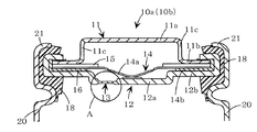
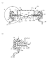
以下に、本発明の密閉型電池をリチウムイオン電池に適用した場合の好ましい実施の形態を図1〜図3に基づいて説明するが、本発明はこの実施の形態に何ら限定されるものでなく、本発明の目的を変更しない範囲で適宜変更して実施することが可能である。なお、図1は本発明の封口体をリチウムイオン電池の外装缶の開口部に取り付けた状態の要部を示す断面図である。また、図2は図1の封口体のA部を拡大した実施例1の封口体を示す図であり、図2(a)は断面図であり、図2(b)は図2(a)のノッチ部の平面形状を示す上面図である。また、図3は図1の封口体のA部を拡大した実施例2の封口体を示す図であり、図3(a)は断面図であり、図3(b)は図3(a)のノッチ部の平面形状を示す上面図である。
【0017】
1.封口体の作製
本発明の封口体10a(10b)は、逆皿状(キャップ状)に形成された正極キャップとなる第1弁キャップ11と、皿状に形成された底蓋となる第2弁キャップ12とから構成される。第1弁キャップ11は、ステンレスにより形成されていて電池外部に向けて膨出する凸部11aと、この凸部11aの底辺部を構成する平板状のフランジ部11bとからなり、凸部11aの角部には複数のガス抜き孔11cを設けている。一方、第2弁キャップ12はステンレスにより形成されていて電池内部に向けて膨出する凹部12aと、この凹部12aの底辺部を構成する平板状のフランジ部12bとからなる。そして、この凹部12bの一部には肉薄部13が設けられており、この肉薄部13には電池内部の圧力が第2の設定圧力(例えば0.78〜1.08MPa)に達すると破断して、第2弁キャップ12の内外を連通する後述するノッチ部13a(13b)が形成されている。
【0018】
これらの第1弁キャップ11と第2弁キャップ12との内部には、電池内部のガス圧が上昇して第1の設定圧力(例えば14MPa)に達すると変形する導電性弾性変形板14が収容されている。この導電性弾性変形板14は弁部材となるものであって、凹部14aとフランジ部14bとからなり、例えば、厚みが0.2mmで表面の凹凸が0.005mmのアルミニウム箔から構成される。凹部14aの最低部は第2弁キャップ12の凹部12aの上表面に超音波溶着またはレーザ溶接等により固着して配設されており、フランジ部14bは第1弁キャップ11のフランジ部11bと第2弁キャップ12のフランジ部12bとの間に狭持されている。
【0019】
フランジ部14bの上部の一部には、PTC(Positive Temperature Coefficient)サーミスタ素子15が配設され、電池内に過電流が流れて異常な発熱現象を生じると、このPTCサーミスタ素子15の抵抗値が増大して過電流を減少させる。そして、電池内部のガス圧が上昇して第1の設定圧力(例えば14MPa)以上になると導電性弾性変形板14の凹部14aは変形する。このため、超音波溶着またはレーザ溶接等により固着された部分が剥がれて、導電性弾性変形板14と第2弁キャップ12の凹部12aとの接触が遮断され、過電流あるいは短絡電流が遮断されるようになる。また、過電流あるいは短絡電流が遮断された後、さらに電池内部のガス圧が上昇すると導電性弾性変形板14に形成されているノッチが開裂して、ガスがガス抜き孔11cから放出されるようになっている。
【0020】
そして、第2弁キャップ12のフランジ部12aの上に、断面形状がL字状で厚みが0.25mmでポリプロピレン(PP)製のリング状封口体用ガスケット16を載置するとともに、この封口体用ガスケット16の上に導電性弾性変形板14のフランジ部14bおよびPTCサーミスタ素子15を載置した。ついで、封口体用絶縁ガスケット16の下面と第2弁キャップ12のフランジ部12bの上面との接触部を熱溶着あるいは接着剤による接着により密着一体化させた。この後、第2弁キャップ12のフランジ部12bの端部を内方にかしめ加工することにより、第1弁キャップ11は封口体用ガスケット16を介して第2弁キャップ12のフランジ部12bにより保持されることとなる。
【0021】
ここで、図2(a),(b)に示すように、肉薄部13に平面形状が略C字形状のV溝からなるノッチ部13a(なお、このノッチ部13aは破断圧力が0.78〜1.08MPa(第2の設定圧力)になるように設定されている)を形成した第2弁キャップ12を用いたものを実施例1の封口体10aとした。また、図3(a),(b)に示すように、肉薄部13に平面形状が十字状のV溝からなるノッチ部13b(なお、このノッチ部13bは破断圧力が0.78〜1.08MPa(第2の設定圧力)になるように設定されている)を形成した第2弁キャップ12を用いたものを実施例2の封口体10bとした。
【0022】
2.リチウムイオン電池の作製
ついで、上述したように構成した封口体10a、10bを用いた実施例1,2のリチウムイオン電池A,Bの作製法、および図7に示すように、肉薄部がなく凹部32aの角部にガス抜き孔32cが設けられた封口体30を用いた比較例のリチウムイオン電池Xの作製法について説明する。
【0023】
まず、天然黒鉛よりなる負極活物質とポリビニリデンフルオライト(PVDF)よりなる結着剤等とを、N−メチルピロリドンからなる有機溶剤等に溶解したものを混合して、スラリーあるいはペーストとした。これらのスラリーあるいはペーストを、スラリーの場合はダイコーター、ドクターブレード等を用いて、ペーストの場合はローラコーティング法等により金属芯体(例えば、銅箔)の両面の全面にわたって均一に塗布して、活物質層を塗布した負極板を形成した。この後、活物質層を塗布した負極板を乾燥機中を通過させて、スラリーあるいはペースト作製に必要であった有機溶剤を除去して乾燥させた。この乾燥負極板をロールプレス機により圧延した後、所定の形状に切断して負極板とした。
【0024】
一方、LiCoO2からなる正極活物質と、アセチレンブラック、グラファイト等の炭素系導電剤と、ポリビニリデンフルオライト(PVDF)よりなる結着剤等とを、N−メチルピロリドンからなる有機溶剤等に溶解したものを混合して、スラリーあるいはペーストとした。これらのスラリーあるいはペーストを、スラリーの場合はダイコーター、ドクターブレード等を用いて、ペーストの場合はローラコーティング法等により金属芯体(例えば、アルミニウム箔)の両面に均一に塗布して、活物質層を塗布した正極板を形成した。この後、活物質層を塗布した正極板を乾燥機中を通過させて、スラリーあるいはペースト作製に必要であった有機溶剤を除去して乾燥させた後、この乾燥正極板をロールプレス機により圧延し、所定の形状に切断して正極板とした。
【0025】
上述のようにして作製した負極板と正極板とを、有機溶媒との反応性が低く、かつ安価なポリオレフィン系樹脂からなる微多孔膜、好適にはポリエチレン製微多孔膜(セパレータ)を間にして重ね合わせ、巻き取り機により卷回した。この後、最外周をテープ止めして渦巻状電極体とした。ついで、ステンレス製の負極端子を兼ねる有底筒状の円筒形外装缶20の開口部21より、上述のようにして作製した渦巻状電極体の上下にそれぞれ絶縁板を配置した後、この渦巻状電極体を外装缶20内に挿入した。このとき、渦巻状電極体の負極板より延出する負極導電タブを外装缶に溶接した。一方、渦巻状電極体の正極板より延出する正極導電タブを封口体10a(10b,30)の第2弁キャップ12の凹部12aの下面に溶接した。
【0026】
この後、外装缶20内にエチレンカーボネート(EC)30重量部とジエチルカーボネート(DEC)70重量部よりなる混合溶媒に電解質塩として1MLiPF6を添加した電解液を注入した。ついで、外装缶20の開口部21にポリプロピレン(PP)製で厚みが0.4mmで大径部と小径部を有する円筒状の外装缶用ガスケット18(36)を載置するとともに、この外装缶用ガスケット18(36)の内部に封口体10a(10b,30)を載置した。この後、外装缶20の開口部21の上端部を内方にかしめることにより封口して、リチウムイオン電池A,B,Xをそれぞれ作製した。ここで、実施例1の封口体10aを用いて作製したものをリチウムイオン電池Aとし、実施例2の封口体10bを用いて作製したものをリチウムイオン電池Bとし、封口体30を用いて作製したものをリチウムイオン電池Xとした。
【0027】
3.落下実験(漏液試験)
ついで、上述のように作製したリチウムイオン電池A,B,Xをそれぞれ10個ずつ用意して、これらの各10個ずつのリチウムイオン電池をコンクリート上に1.5mの高さから落下させたときに、漏液(リーク)が発生した電池の個数を測定すると、下記の表1に示すような結果となった。なお、この漏液試験においては、電池を封口体10a(10b,30)を下向きにして1回落下させた後、封口体10a(10b,30)を上向きにして1回落下させ、ついで、電池の側面を下向きにして1回落下させて1セットとし、これを30セット行った。
【0028】
【表1】

上記表1の結果から明らかなように、電池A,Bにおいては、コンクリート上に1.5mの高さから落下させたに係わらず、漏液個数が0であるのに対して、電池Xにおいては10個の内3個(30%)の電池に漏液が生じていたことが分かる。
これは、電池Xにおいては、第2弁キャップ32の凹部32aの角部にガス抜き孔32cが設けられているため、落下の衝撃により封口体30の密閉性が壊れて、ガス抜き孔32cを通して電解液が電池外部にリークしたと考えられる。
一方、電池A,Bにおいては、第2弁キャップ12の薄肉部13にノッチ部13a(13b)が設けられているため、落下の衝撃により封口体10a,10bの密閉性が壊れることはなく、したがって、漏液が生じることはないためである。
【0030】
4.変形例
上述の実施形態においては、肉薄部13に平面形状が略C字形状のV溝からなるノッチ部13aを形成する例、あるいは肉薄部13に平面形状が十字状のV溝からなるノッチ部13bを形成する例について説明したが、これらの形状以外に種々の変形が可能である。以下に、変形例について説明する。
【0031】
(1)第1変形例
本第1変形例においては、図4(なお、図4(a)は第1変形例の封口体10cのA部を拡大して示す断面図であり、図4(b)は図4(a)のノッチ部13cの平面形状を示す上面図である)に示すように、第2弁キャップ12の薄肉部13に略日字形状のV字溝を形成してノッチ部13cとし、この第2弁キャップ12を用いて封口体10cを形成するようにしている。この場合、一部が連結するようにして、破壊が生じても弁部が電池内に脱落することがないようにするのが望ましい。
【0032】
(2)第2変形例
本第2変形例においては、図5(なお、図5(a)は第2変形例の封口体10dのA部を拡大して示す断面図であり、図5(b)は図5(a)のノッチ部13dの平面形状を示す上面図である)に示すように、第2弁キャップ12の薄肉部13に楕円形状のV字溝を形成してノッチ部13dとし、この第2弁キャップ12を用いて封口体10dを形成するようにしている。この場合も、一部が連結するようにして、破壊が生じても弁部が電池内に脱落することがないようにするのが望ましい。
【0033】
(3)第3変形例
本第3変形例においては、図6(なお、図6(a)は第3変形例の封口体10eのA部を拡大して示す断面図であり、図6(b)は図6(a)のノッチ部13eの平面形状を示す上面図である)に示すように、第2弁キャップ12の薄肉部13に真円形状のV字溝を形成してノッチ部13eとし、この第2弁キャップ12を用いて封口体10eを形成するようにしている。この場合も、一部が連結するようにして、破壊が生じても弁部が電池内に脱落することがないようにするのが望ましい。
【0034】
【発明の効果】
上述したように、本発明においては、第2弁キャップ12の薄肉部13にノッチ部13a(13b,13c,13d,13e)を備えるとともに、このノッチ部13a(13b,13c,13d,13e)の作動圧力を導電性弾性変形板14が電流遮断する圧力よりも低くなるように設定されている。このため、落下などの衝撃を受けて封口体10a(b,c,d,e)が変形しても封口体10a(b,c,d,e)の密閉性を維持することができ、電解液が電池外部にリークすることを未然に防止することが可能となる。
【0035】
そして、過充電などにより電池内圧が上昇した場合においては、ノッチ部13a(13b,13c,13d,13e)の作動圧力(第2の設定圧力)を導電性弾性変形板14が電流遮断する圧力(第1の設定圧力)よりも低くなるように設定されているので、まずノッチ部13a(13b,13c,13d,13e)が作動してノッチ部13a(13b,13c,13d,13e)での密閉性が破壊された後、さらに圧力が上昇して導電性弾性変形板14の作動圧力に達すると、導電性弾性変形板14が電流遮断するように作動するため、過充電によるガス発生を防止できるようになる。
【0036】
なお、上述の実施形態においては、負極活物質として天然黒鉛を用いる例について説明したが、天然黒鉛以外に、リチウムイオンを吸蔵・脱離し得るカーボン系材料、例えば、グラファイト、カーボンブラック、コークス、ガラス状炭素、炭素繊維、またはこれらの焼成体等が好適である。また、酸化錫、酸化チタン等のリチウムイオンを吸蔵・脱離し得る酸化物を用いてもよい。
【0037】
また、上述の実施形態においては、正極活物質としてLiCoO2を用いる例について説明したが、LiCoO2以外に、リチウムイオンをゲストとして受け入れ得るリチウム含有遷移金属化合物、例えば、LiNiO2、LiCoXNi(1−X)O2、LiCrO2、LiVO2、LiMnO2、αLiFeO2、LiTiO2、LiScO2、LiYO2、LiMn2O4等が好ましいが、特に、LiNiO2、LiCoXNi(1−X)O2を単独で用いるかあるいはこれらの二種以上を混合して用いるのが好適である。また、ポリアセチレン、ポリアニリン等の導電性ポリマーを用いてもよい。
【0038】
さらに、電解液としては、有機溶媒に溶質としてリチウム塩を溶解したイオン伝導体であって、イオン伝導率が高く、正・負の各電極に対して化学的、電気化学的に安定で、使用可能温度範囲が広くかつ安全性が高く、安価なものであれば使用することができる。例えば、有機溶媒としては上記エチレンカーボネート(EC)とジエチルカーボネート(DEC)との混合溶媒以外に、プロピレンカーボネート(PC)、スルフォラン(SL)、テトラハイドロフラン(THF)、γブチロラクトン(GBL)、ジメチルカーボネート(DMC)、エチルメチルカーボネート(EMC)、1,2ジメトキシエタン(DME)等あるいはこれらの混合溶媒が好適である。また、溶質としては電子吸引性の強いリチウム塩を使用し、上記LiPF6以外に例えば、LiBF4、LiClO4、LiAsF6、LiCF3SO3、Li(CF3SO2)2N、LiC4F9SO3等が好適である。
【0039】
なお、上述の実施形態においては、本発明をリチウムイオン電池に適用する例について説明したが、リチウムイオン電池以外に、ニッケル−カドミウム蓄電池、ニッケル−水素蓄電池などの各種の密閉型電池においても本発明を適用することが可能である。
【図面の簡単な説明】
【図1】 本発明の封口体をリチウムイオン電池の外装缶に取り付けた状態の要部を示す断面図である。
【図2】 図1の封口体のA部を拡大した実施例1の封口体を示す図であり、図2(a)は断面図であり、図2(b)は図2(a)のノッチ部の平面形状を示す上面図である。
【図3】 図1の封口体のA部を拡大した実施例2の封口体を示す図であり、図3(a)は断面図であり、図3(b)は図3(a)のノッチ部の平面形状を示す上面図である。
【図4】 図1の封口体のA部を拡大した変形例1の封口体を示す図であり、図4(a)は断面図であり、図4(b)は図4(a)のノッチ部の平面形状を示す上面図である。
【図5】 図1の封口体のA部を拡大した変形例2の封口体を示す図であり、図5(a)は断面図であり、図5(b)は図5(a)のノッチ部の平面形状を示す上面図である。
【図6】 図1の封口体のA部を拡大した変形例3の封口体を示す図であり、図6(a)は断面図であり、図6(b)は図6(a)のノッチ部の平面形状を示す上面図である。
【図7】 従来例の封口体を示す図であり、図7(a)は封口体をリチウムイオン電池の外装缶に取り付けた状態の要部を示す断面図であり、図7(b)は図7(a)のB部を拡大して示す断面図である。
【符号の説明】
10a,10b…封口体、11…第1弁キャップ、11a…凸部、11b…フランジ部、11c…ガス抜き孔、12…第2弁キャップ、12a…凹部、12b…フランジ部、13…薄肉部、13a,13b,13c,13d,13e…ノッチ部、14…導電性弾性変形板、14a…凹部、14b…フランジ部、15…PTCサーミスタ素子、16…封口体用ガスケット、18…外装缶用ガスケット、20…外装缶、21…開口部[0001]
BACKGROUND OF THE INVENTION
The present invention relates to a sealed battery having a sealing body at the opening of a metal outer can, and in particular, includes a sealing body having a safety mechanism capable of interrupting an overcharge current during overcharge or a short circuit current during short circuit. The present invention relates to a sealed battery.
[0002]
[Prior art]
Generally, in non-aqueous electrolyte secondary batteries such as lithium-ion batteries, when a device including a charger fails or is overcharged or misused, the power generation elements such as the electrolyte and active material inside the battery undergo chemical changes. Wake up. For example, the electrolyte solution or the active material is decomposed by an abnormal reaction due to overcharge or short circuit, and abnormally gas is generated inside the battery, so that the battery internal pressure becomes excessive. In such a case, there is a risk of the battery exploding or damaging the equipment used, so a safety mechanism has been conventionally added to this type of battery. As a battery to which such a safety mechanism is added, for example, Patent Document 1 (Japanese Patent Laid-Open No. 2000-36293) is known.
[0003]
As shown in FIG. 7A, the non-aqueous electrolyte battery proposed in Patent Document 1 is formed in a dish shape with a stainless steel first valve cap 31 formed in an inverted dish shape (cap shape). The sealing
[0004]
Inside these first valve cap 31 and
[0005]
A PTC (Positive Temperature Coefficient)
[0006]
In this case, a sealing member gasket 35 made of polypropylene (PP) is placed on the
[Patent Document 1]
JP 2000-36293 A
[0007]
[Problems to be solved by the invention]
By the way, in the battery provided with the sealing
[0008]
However, when the battery provided with the sealing
[0009]
However, since the sealing
[0010]
Further, metal parts are in direct contact between the flange portion 31b of the first valve cap 31 and the
[0011]
For this reason, in order to improve the sealing performance, various studies were made on the sealing material, gasket material, gasket shape, caulking shape, etc., but when the battery was deformed, the sealing performance at the gasket portion for the sealing body and the contact between the metal parts It was difficult to ensure the sealability at the part.
Therefore, the present invention has been made in view of the above problems, and an object thereof is to provide a sealed battery with improved sealing performance while maintaining a safety mechanism.
[0012]
[Means for Solving the Problems]
In order to achieve the above object, a sealed battery according to the present invention includes a first valve cap serving as an external terminal. (11) And the first valve cap (11) The Through the gasket for sealing body (16) A second valve cap that is held and electrically connected to one electrode in the battery (12) The second valve cap is elastically deformed when the battery internal pressure rises to the first set pressure, and is disposed in the opening of the metal outer can containing the power generation element. (12) A conductive elastic deformation plate for cutting off an electrical connection state with the first valve cap; (11) And second valve cap (12) And a second valve cap having a notch portion that breaks when the battery internal pressure reaches a second set pressure lower than the first set pressure. (12) Integrated into a part of The end of the flange portion of the first valve cap (11) is caulked by the end of the flange portion of the second valve cap (12). It is characterized by that.
[0013]
Thus, until the battery internal pressure reaches the second set pressure, the second valve cap (12) Since the inside of the battery is kept in a sealed state, even if the sealing body is deformed due to an impact such as dropping, the sealing body can be kept hermetically sealed, and it is possible to prevent the electrolyte from leaking to the outside of the battery. It becomes possible to prevent. When the battery internal pressure reaches the second set pressure, the second valve cap (12) Since the notch part integrally formed in a part of the battery is broken, the inside of the battery is kept sealed by the conductive elastic deformation plate until the first set pressure is reached. Thereafter, when the battery internal pressure reaches the first set pressure, the conductive elastic deformation plate is deformed, and the conductive elastic deformation plate and the second valve cap (12) The electrical connection state with is cut off.
[0014]
In this case, the first valve cap (11) Has a flange portion and a convex portion that bulges toward the outside of the battery, and a second valve cap (12) Includes a flange portion and a concave portion that bulges toward the inside of the battery, and the peripheral portion of the conductive elastic deformation plate is a first valve cap. (11) Flange and second valve cap (12) The first valve cap is disposed between the flange portion of the (11) The end of the flange part of the second valve cap (12) If the end portion of the flange portion is caulked, the conductive elastic deformation plate is deformed and reversed, and the diameter of reversal does not increase. Therefore, the operating pressure for elastically deforming the conductive elastic deformation plate becomes uniform.
[0015]
The notch shape for forming the notch portion may be any shape as long as the pressure is uniform, but the planar shape is approximately C-shaped, cross-shaped, elliptical, perfect circular, approximately The V-shaped groove is desirable because a stable operating pressure can be obtained. In particular, the substantially C-shaped and cruciform shape is preferable because the valve portion does not fall into the battery even if it is broken. .
[0016]
DETAILED DESCRIPTION OF THE INVENTION
Hereinafter, a preferred embodiment when the sealed battery of the present invention is applied to a lithium ion battery will be described with reference to FIGS. 1 to 3, but the present invention is not limited to this embodiment. The present invention can be implemented with appropriate modifications without changing the object of the present invention. FIG. 1 is a cross-sectional view showing a main part in a state where the sealing body of the present invention is attached to the opening of the outer can of the lithium ion battery. Moreover, FIG. 2 is a figure which shows the sealing body of Example 1 which expanded the A section of the sealing body of FIG. 1, FIG. 2 (a) is sectional drawing, FIG.2 (b) is FIG.2 (a). It is a top view which shows the planar shape of a notch part. Moreover, FIG. 3 is a figure which shows the sealing body of Example 2 which expanded the A section of the sealing body of FIG. 1, FIG. 3 (a) is sectional drawing, FIG.3 (b) is FIG.3 (a). It is a top view which shows the planar shape of a notch part.
[0017]
1. Production of sealing body
Sealing body of the
[0018]
Inside these first valve cap 11 and
[0019]
A PTC (Positive Temperature Coefficient)
[0020]
Then, on the
[0021]
Here, as shown in FIGS. 2A and 2B, the
[0022]
2. Fabrication of lithium ion battery
Next, as shown in FIGS. 7A and 7B, the manufacturing method of the lithium ion batteries A and B of Examples 1 and 2 using the sealing
[0023]
First, a negative electrode active material made of natural graphite and a binder made of polyvinylidene fluoride (PVDF) dissolved in an organic solvent made of N-methylpyrrolidone were mixed to obtain a slurry or paste. Apply these slurries or pastes uniformly in the case of a slurry using a die coater, a doctor blade, etc., and in the case of a paste, the entire surface of both sides of a metal core (for example, copper foil) by a roller coating method, A negative electrode plate coated with an active material layer was formed. Thereafter, the negative electrode plate coated with the active material layer was passed through a drier to remove the organic solvent necessary for slurry or paste preparation and dried. The dried negative electrode plate was rolled with a roll press and then cut into a predetermined shape to obtain a negative electrode plate.
[0024]
On the other hand, LiCoO 2 A mixture of a positive electrode active material comprising, a carbon conductive agent such as acetylene black and graphite, and a binder comprising polyvinylidene fluoride (PVDF) dissolved in an organic solvent comprising N-methylpyrrolidone. Thus, a slurry or paste was obtained. Apply these slurries or pastes uniformly on both sides of a metal core (for example, aluminum foil) by using a die coater, doctor blade, etc. in the case of a slurry, or a roller coating method in the case of a paste. A positive electrode plate coated with the layer was formed. Thereafter, the positive electrode plate coated with the active material layer is passed through a dryer to remove the organic solvent necessary for slurry or paste preparation and dried, and then the dried positive plate is rolled by a roll press. Then, it was cut into a predetermined shape to obtain a positive electrode plate.
[0025]
The negative electrode plate and the positive electrode plate produced as described above are sandwiched between a microporous film made of a polyolefin-based resin that has low reactivity with an organic solvent and is inexpensive, preferably a polyethylene microporous film (separator). And then wound with a winder. Thereafter, the outermost periphery was taped to form a spiral electrode body. Next, after the insulating plates are arranged above and below the spiral electrode body produced as described above from the
[0026]
Thereafter, 1 M LiPF as an electrolyte salt in a mixed solvent composed of 30 parts by weight of ethylene carbonate (EC) and 70 parts by weight of diethyl carbonate (DEC) in the
[0027]
3. Drop experiment (leak test)
Next, 10 lithium ion batteries A, B, and X prepared as described above were prepared, and each 10 lithium ion batteries were dropped on concrete from a height of 1.5 m. Further, when the number of batteries in which liquid leakage occurred was measured, the results shown in Table 1 below were obtained. In this liquid leakage test, the battery was dropped once with the sealing
[0028]
[Table 1]
As is clear from the results in Table 1 above, in the batteries A and B, the number of liquid leaks was 0 in spite of being dropped from a height of 1.5 m on the concrete, whereas in the battery X It can be seen that liquid leakage occurred in 3 (30%) of the 10 batteries.
In the battery X, since the gas vent holes 32c are provided at the corners of the
On the other hand, in the batteries A and B, since the notched
[0030]
4). Modified example
In the above-described embodiment, an example in which the
[0031]
(1) First modification
In the first modified example, FIG. 4 (note that FIG. 4A is an enlarged cross-sectional view showing a portion A of the sealing
[0032]
(2) Second modification
In the second modification, FIG. 5 (note that FIG. 5 (a) is an enlarged cross-sectional view showing a portion A of the sealing
[0033]
(3) Third modification
In the third modified example, FIG. 6 (note that FIG. 6A is an enlarged cross-sectional view showing a portion A of the sealing
[0034]
【The invention's effect】
As described above, in the present invention, the
[0035]
When the internal pressure of the battery increases due to overcharging or the like, the pressure (second set pressure) of the
[0036]
In the above-described embodiment, an example in which natural graphite is used as the negative electrode active material has been described. However, in addition to natural graphite, a carbon-based material that can occlude / desorb lithium ions, such as graphite, carbon black, coke, and glass. Like carbon, carbon fiber, or a fired body thereof is preferable. Further, an oxide capable of inserting and extracting lithium ions such as tin oxide and titanium oxide may be used.
[0037]
In the above-described embodiment, LiCoO is used as the positive electrode active material. 2 An example of using LiCoO has been described. 2 In addition, lithium-containing transition metal compounds that can accept lithium ions as guests, such as LiNiO 2 LiCoXNi (1-X) O 2 , LiCrO 2 , LiVO 2 LiMnO 2 , ΑLiFeO 2 LiTiO 2 , LiScO 2 , LiYO 2 , LiMn 2 O Four Etc. are preferable, and in particular, LiNiO 2 LiCoXNi (1-X) O 2 It is preferable to use these alone or as a mixture of two or more thereof. Further, a conductive polymer such as polyacetylene or polyaniline may be used.
[0038]
Furthermore, the electrolyte is an ionic conductor in which a lithium salt is dissolved as a solute in an organic solvent, has high ionic conductivity, is chemically and electrochemically stable for both positive and negative electrodes, and is used. If the possible temperature range is wide, the safety is high, and the cost is low, it can be used. For example, as the organic solvent, in addition to the mixed solvent of ethylene carbonate (EC) and diethyl carbonate (DEC), propylene carbonate (PC), sulfolane (SL), tetrahydrofuran (THF), γ-butyrolactone (GBL), dimethyl Carbonate (DMC), ethyl methyl carbonate (EMC), 1,2 dimethoxyethane (DME) and the like, or a mixed solvent thereof is preferable. In addition, a lithium salt having a strong electron-withdrawing property is used as the solute, and the above LiPF 6 For example, LiBF Four LiClO Four , LiAsF 6 , LiCF Three SO Three , Li (CF Three SO 2 ) 2 N, LiC Four F 9 SO Three Etc. are suitable.
[0039]
In the above-described embodiment, an example in which the present invention is applied to a lithium ion battery has been described. However, in addition to the lithium ion battery, the present invention is also applied to various sealed batteries such as a nickel-cadmium storage battery and a nickel-hydrogen storage battery. It is possible to apply.
[Brief description of the drawings]
FIG. 1 is a cross-sectional view showing a main part in a state where a sealing body of the present invention is attached to an outer can of a lithium ion battery.
2 is a view showing a sealing body of Example 1 in which a portion A of the sealing body of FIG. 1 is enlarged, FIG. 2 (a) is a cross-sectional view, and FIG. 2 (b) is a cross-sectional view of FIG. It is a top view which shows the planar shape of a notch part.
3 is a view showing a sealing body of Example 2 in which a portion A of the sealing body of FIG. 1 is enlarged, FIG. 3 (a) is a sectional view, and FIG. 3 (b) is a cross-sectional view of FIG. It is a top view which shows the planar shape of a notch part.
4 is a view showing a sealing body of Modification 1 in which an A portion of the sealing body of FIG. 1 is enlarged, FIG. 4 (a) is a cross-sectional view, and FIG. 4 (b) is a cross-sectional view of FIG. It is a top view which shows the planar shape of a notch part.
5 is a view showing a sealing body of Modification 2 in which the portion A of the sealing body of FIG. 1 is enlarged, FIG. 5 (a) is a cross-sectional view, and FIG. 5 (b) is a cross-sectional view of FIG. It is a top view which shows the planar shape of a notch part.
6 is a view showing a sealing body of Modification 3 in which the portion A of the sealing body of FIG. 1 is enlarged, FIG. 6 (a) is a cross-sectional view, and FIG. 6 (b) is a cross-sectional view of FIG. It is a top view which shows the planar shape of a notch part.
FIG. 7 is a view showing a sealing body of a conventional example, FIG. 7 (a) is a cross-sectional view showing a main part in a state where the sealing body is attached to an outer can of a lithium ion battery, and FIG. It is sectional drawing which expands and shows the B section of Fig.7 (a).
[Explanation of symbols]
10a, 10b ... Sealing body, 11 ... 1st valve cap, 11a ... Convex part, 11b ... Flange part, 11c ... Gas vent hole, 12 ... 2nd valve cap, 12a ... Concave part, 12b ... Flange part, 13 ... Thin part , 13a, 13b, 13c, 13d, 13e ... notch part, 14 ... conductive elastic deformation plate, 14a ... concave part, 14b ... flange part, 15 ... PTC thermistor element, 16 ... gasket for sealing body, 18 ... gasket for outer can , 20 ... exterior can, 21 ... opening
Claims (3)
電池内圧が前記第1の設定圧力よりも低い第2の設定圧力に達すると破断するノッチ部を前記第2弁キャップ(12)の一部に一体的に備えるとともに、
前記第1弁キャップ(11)のフランジ部の端部は前記第2弁キャップ(12)のフランジ部の端部によりかしめ付けされていることを特徴とする密閉型電池。Second valve cap is conductively connected to one electrode of the battery holds via a first valve cap comprising an external terminal (11) and the sealing-body gasket first valve cap (11) (16) ( 12) is disposed in the opening of the metal outer can containing the power generation element, and elastically deforms when the battery internal pressure rises to the first set pressure, and the second valve cap (12). A sealed battery comprising a conductive elastic deformation plate that cuts off an electrical connection state between the first valve cap (11) and the second valve cap (12) in a conductive connection state therebetween. ,
Battery internal pressure of the first lower than the set pressure second Rutotomoni integrally provided with a portion of the setting the second valve cap notch to break to reach the pressure (12),
The sealed battery according to claim 1, wherein an end portion of the flange portion of the first valve cap (11) is caulked by an end portion of the flange portion of the second valve cap (12) .
前記導電性弾性変形板の周辺部は前記第1弁キャップ(11)のフランジ部と電気的に接触して該フランジ部と前記第2弁キャップ(12)のフランジ部との間に封口体用ガスケットを介して配置され、かつ前記導電性弾性変形板の中心部は前記第2弁キャップ(12)の凹部の一部と電気的に接触して配置され、
前記第1弁キャップ(11)のフランジ部の端部は前記第2弁キャップ(12)のフランジ部の端部によりかしめ付けされていることを特徴とする請求項1に記載の密閉型電池。The first valve cap (11) includes a flange portion and a convex portion that bulges toward the outside of the battery, and the second valve cap (12) includes a flange portion and a concave portion that bulges toward the inside of the battery. With
The peripheral portion of the conductive elastic deformation plate is in electrical contact with the flange portion of the first valve cap (11) and is used for a sealing body between the flange portion and the flange portion of the second valve cap (12). Disposed through a gasket, and the central portion of the conductive elastic deformation plate is disposed in electrical contact with a part of the recess of the second valve cap (12) ;
The sealed battery according to claim 1, wherein an end portion of the flange portion of the first valve cap (11) is caulked by an end portion of the flange portion of the second valve cap (12) .
Priority Applications (1)
| Application Number | Priority Date | Filing Date | Title |
|---|---|---|---|
| JP2002302540A JP4104416B2 (en) | 2002-10-17 | 2002-10-17 | Sealed battery |
Applications Claiming Priority (1)
| Application Number | Priority Date | Filing Date | Title |
|---|---|---|---|
| JP2002302540A JP4104416B2 (en) | 2002-10-17 | 2002-10-17 | Sealed battery |
Publications (2)
| Publication Number | Publication Date |
|---|---|
| JP2004139809A JP2004139809A (en) | 2004-05-13 |
| JP4104416B2 true JP4104416B2 (en) | 2008-06-18 |
Family
ID=32450578
Family Applications (1)
| Application Number | Title | Priority Date | Filing Date |
|---|---|---|---|
| JP2002302540A Expired - Fee Related JP4104416B2 (en) | 2002-10-17 | 2002-10-17 | Sealed battery |
Country Status (1)
| Country | Link |
|---|---|
| JP (1) | JP4104416B2 (en) |
Families Citing this family (4)
| Publication number | Priority date | Publication date | Assignee | Title |
|---|---|---|---|---|
| JP4854208B2 (en) * | 2005-03-09 | 2012-01-18 | 三洋電機株式会社 | Sealed battery and manufacturing method thereof |
| US8993138B2 (en) * | 2008-10-02 | 2015-03-31 | Samsung Sdi Co., Ltd. | Rechargeable battery |
| KR20100065670A (en) * | 2008-12-08 | 2010-06-17 | 삼성에스디아이 주식회사 | Rechargeable battery |
| US10403872B2 (en) | 2015-03-27 | 2019-09-03 | Sanyo Electric Co., Ltd. | Cylindrical batteries |
-
2002
- 2002-10-17 JP JP2002302540A patent/JP4104416B2/en not_active Expired - Fee Related
Also Published As
| Publication number | Publication date |
|---|---|
| JP2004139809A (en) | 2004-05-13 |
Similar Documents
| Publication | Publication Date | Title |
|---|---|---|
| JP4854208B2 (en) | Sealed battery and manufacturing method thereof | |
| US10985400B2 (en) | Nonaqueous electrolyte secondary battery and method for manufacturing the same | |
| KR100841905B1 (en) | Secondary cell and method for preparation thereof | |
| US6632572B1 (en) | Lithium secondary battery | |
| KR101263601B1 (en) | Gel electrolyte and gel electrolyte battery | |
| JP4236308B2 (en) | Lithium ion battery | |
| KR20010062467A (en) | Nonaqueous Secondary Battery and Method of Manufacturing Thereof | |
| TWI509863B (en) | Prismatic storage battery or cell with flexible recessed portion | |
| KR20160037518A (en) | Cylindrical Battery Including Pressuring Part and Manufacturing Method for the Same | |
| JP4053802B2 (en) | Electrochemical devices | |
| JP2008251187A (en) | Sealed battery | |
| KR100942906B1 (en) | Electrochemical device ensuring a good safety | |
| JP4984359B2 (en) | Sealed battery and its sealing plate | |
| JP4104416B2 (en) | Sealed battery | |
| JP2939468B1 (en) | Electrolyte for non-aqueous battery and secondary battery using this electrolyte | |
| US9406924B2 (en) | Nonaqueous electrolyte secondary battery | |
| JP2006302509A (en) | Battery | |
| JP4420484B2 (en) | Sealed battery | |
| KR20130131983A (en) | Secondary battery comprising apparatus for preventing overcharge | |
| KR100659860B1 (en) | Electrode for a rechargeable battery and the battery employing the same | |
| JP4107722B2 (en) | Sealed battery | |
| JP2000277063A (en) | Sealed battery | |
| KR19980073911A (en) | Lithium polymer secondary battery with short-circuit insulation layer | |
| JP4018881B2 (en) | Electrochemical devices | |
| JP4115006B2 (en) | Lithium ion battery |
Legal Events
| Date | Code | Title | Description |
|---|---|---|---|
| A621 | Written request for application examination |
Free format text: JAPANESE INTERMEDIATE CODE: A621 Effective date: 20051013 |
|
| A131 | Notification of reasons for refusal |
Free format text: JAPANESE INTERMEDIATE CODE: A131 Effective date: 20071204 |
|
| A521 | Written amendment |
Free format text: JAPANESE INTERMEDIATE CODE: A523 Effective date: 20080131 |
|
| TRDD | Decision of grant or rejection written | ||
| A01 | Written decision to grant a patent or to grant a registration (utility model) |
Free format text: JAPANESE INTERMEDIATE CODE: A01 Effective date: 20080226 |
|
| A61 | First payment of annual fees (during grant procedure) |
Free format text: JAPANESE INTERMEDIATE CODE: A61 Effective date: 20080325 |
|
| FPAY | Renewal fee payment (event date is renewal date of database) |
Free format text: PAYMENT UNTIL: 20110404 Year of fee payment: 3 |
|
| FPAY | Renewal fee payment (event date is renewal date of database) |
Free format text: PAYMENT UNTIL: 20120404 Year of fee payment: 4 |
|
| FPAY | Renewal fee payment (event date is renewal date of database) |
Free format text: PAYMENT UNTIL: 20130404 Year of fee payment: 5 |
|
| LAPS | Cancellation because of no payment of annual fees |