JP4420484B2 - Sealed battery - Google Patents
Sealed battery Download PDFInfo
- Publication number
- JP4420484B2 JP4420484B2 JP08550899A JP8550899A JP4420484B2 JP 4420484 B2 JP4420484 B2 JP 4420484B2 JP 08550899 A JP08550899 A JP 08550899A JP 8550899 A JP8550899 A JP 8550899A JP 4420484 B2 JP4420484 B2 JP 4420484B2
- Authority
- JP
- Japan
- Prior art keywords
- battery
- sealing plate
- convex portion
- gasket
- internal gasket
- Prior art date
- Legal status (The legal status is an assumption and is not a legal conclusion. Google has not performed a legal analysis and makes no representation as to the accuracy of the status listed.)
- Expired - Fee Related
Links
Images


Classifications
-
- Y—GENERAL TAGGING OF NEW TECHNOLOGICAL DEVELOPMENTS; GENERAL TAGGING OF CROSS-SECTIONAL TECHNOLOGIES SPANNING OVER SEVERAL SECTIONS OF THE IPC; TECHNICAL SUBJECTS COVERED BY FORMER USPC CROSS-REFERENCE ART COLLECTIONS [XRACs] AND DIGESTS
- Y02—TECHNOLOGIES OR APPLICATIONS FOR MITIGATION OR ADAPTATION AGAINST CLIMATE CHANGE
- Y02E—REDUCTION OF GREENHOUSE GAS [GHG] EMISSIONS, RELATED TO ENERGY GENERATION, TRANSMISSION OR DISTRIBUTION
- Y02E60/00—Enabling technologies; Technologies with a potential or indirect contribution to GHG emissions mitigation
- Y02E60/10—Energy storage using batteries
-
- Y—GENERAL TAGGING OF NEW TECHNOLOGICAL DEVELOPMENTS; GENERAL TAGGING OF CROSS-SECTIONAL TECHNOLOGIES SPANNING OVER SEVERAL SECTIONS OF THE IPC; TECHNICAL SUBJECTS COVERED BY FORMER USPC CROSS-REFERENCE ART COLLECTIONS [XRACs] AND DIGESTS
- Y02—TECHNOLOGIES OR APPLICATIONS FOR MITIGATION OR ADAPTATION AGAINST CLIMATE CHANGE
- Y02P—CLIMATE CHANGE MITIGATION TECHNOLOGIES IN THE PRODUCTION OR PROCESSING OF GOODS
- Y02P70/00—Climate change mitigation technologies in the production process for final industrial or consumer products
- Y02P70/50—Manufacturing or production processes characterised by the final manufactured product
Landscapes
- Sealing Battery Cases Or Jackets (AREA)
- Gas Exhaust Devices For Batteries (AREA)
- Secondary Cells (AREA)
Description
【0001】
【発明の属する技術分野】
本発明は、内部に発電要素が収納された有底円筒状の外装缶と、この外装缶の開口部に外部ガスケットを介してかしめ固定された封口体とを有すると共に、この封口体は上記外装缶側から順に封止板と内部ガスケットとを有し、この内部ガスケットを介して上記封止板により端子キャップと防爆弁とが挟持される構造の密閉型電池に関する。
【0002】
【従来の技術】
近年、LiCoO2 等のリチウム含有複合酸化物を正極材料とする一方、金属リチウム又はリチウムイオンを吸蔵、放出し得る合金又は炭素材料を負極材料とするリチウムイオン電池が、高容量化が可能な電池として注目されている。このようにリチウムイオン電池は優れた性能を有するということから、円筒型形状の密閉型電池等に用いられている。
【0003】
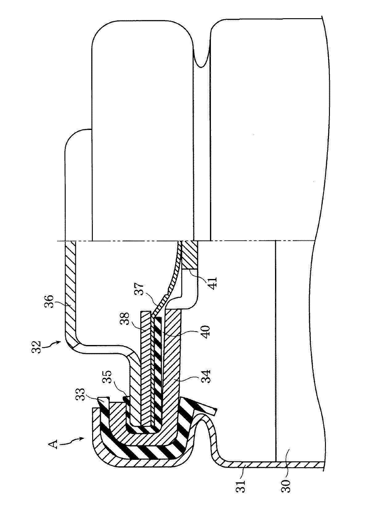
ここで、上記リチウムイオン電池の具体的な構造は、図5に示すように、内部に発電要素30が収納された有底円筒状の外装缶31と、この外装缶31の開口部に外部ガスケット33を介してかしめ固定された封口体32とを有すると共に、この封口体32は上記外装缶31側から順に封止板34と内部ガスケット35とを有し、この内部ガスケット35を介して上記封止板34により端子キャップ36、防爆弁37及びPTC素子38が挟持される構造となっている。
【0004】
しかしながら、上記従来の電池では、封口体32のかしめ固定時に外装缶31の開口端部を電池内部方向(図中A方向)に押圧する必要があり、これに伴って封止板34も電池内部方向に押圧されるので、封止板34が電池内部方向に変形し(たわみ)、封止板34と内部ガスケット35との間に隙間40が形成される。このため、封止板34に形成されたガス抜き孔41から進入した電解液が、隙間40を通って電池外に大量に排出されて、電池外に存在する保護回路等を破損するおそれがある。加えて、内部ガスケット35と防爆弁37との間にも隙間が形成されることがあるため、電解液がこの隙間を通って封口体32内に進入して、封口体32内のPTC素子38を破損するおそれもある。このような不都合は、電池の保存温度が大きく変化するような場合に、特に生じやすくなる。なぜなら、低温では内部ガスケット35は収縮し、高温では内部ガスケット35は膨張するため、このようなことを繰り返すと、内部ガスケット35が徐々に劣化するからである。
【0005】
【発明が解決しようとする課題】
本発明は、以上の事情に鑑みなされたものであって、例え電池の保存温度が大きく変化するような場合であっても、封止板と内部ガスケットとの間及び防爆弁と内部ガスケットとの間に隙間が形成されるのを抑制することにより、電解液が電池外に排出されたり、封口体内に進入したりするのを防止し、これによって、保護回路やPTC素子の破損を抑制することができる密閉型電池の提供を目的とする。
【0006】
【課題を解決するための手段】
上記目的を達成するために、本発明のうちで請求項1記載の発明は、内部に発電要素が収納された有底円筒状の外装缶と、この外装缶の開口部に外部ガスケットを介してかしめ固定された封口体とを有すると共に、この封口体は上記外装缶側から順に封止板と内部ガスケットとを有し、この内部ガスケットを介して上記封止板により端子キャップと防爆弁とが挟持される構造の密閉型電池において、上記封止板は、電池外部及び/又は内部方向に出っ張り、上記封止板の中心を囲む円周状の凸部を備え、上記内部ガスケットは、上記封止板の凸部が電池外部方向に出っ張る凸部である場合には、上記内部ガスケットの電池内部側に、この封止板の凸部と接する位置において、この凸部に対応した凹部が設けられ、上記封止板の凸部が電池内部方向に出っ張る凸部である場合には、上記内部ガスケットの電池内部側に、この凸部に対応した凸部が設けられ、上記封止板と上記内部ガスケットとの間に隙間が形成されないようになされていることを特徴とする
【0007】
このように、封止板に電池外部及び/又は内部方向に出っ張る凸部が形成されていれば、封止板のたわみ強度が飛躍的に向上するので、封口体をかしめ固定する際に、封止板が電池内部方向に押圧された場合であっても、封止板が電池内部方向にたわむのが抑制される。したがって、例え電池の保存温度が大きく変化するような場合であっても、封止板と内部ガスケットとの間及び防爆弁と内部ガスケットとの間に隙間が形成されず、この結果、電解液が電池外に排出されたり、封口体内に進入したりするのを防止できるので、保護回路やPTC素子の破損が抑制される。
また、内部ガスケットが電池外部及び/又は内部方向に出っ張る封止板の凸部の形状に対応するように構成されていなければ、以下の不都合を生じる場合がある。
即ち、凸部が電池外部方向に出っ張る場合には、内部ガスケットに対する押圧力が大き過ぎるため、内部ガスケットの弾性力が十分に発揮されず、しかも内部ガスケットが大きく変形して防爆弁の作動部と接触するため、防爆弁が誤作動するおそれがある。一方、凸部が電池内部方向に出っ張る場合には、内部ガスケットに対する押圧力が小さすぎるため(或いは、押圧力が全く働かないため)、内部ガスケットの弾性力が十分に発揮されない(或いは、弾性力が全く発揮されない)。 これに対して、内部ガスケットが凸部の形状に対応するように構成されていれば、内部ガスケットに適切な押圧力が加えられるため、内部ガスケットの弾性力が十分に発揮されると共に、内部ガスケットが大きく変形しないので、防爆弁が誤作動することもない。したがって、安全性の向上を図りつつ、前記の効果が一層発揮される。
【0011】
また、請求項2記載の発明は、請求項1記載の発明において、上記封止板の厚みに対する上記凸部の高さ割合が50%以上であることを特徴とする。
このように規制するのは、凸部の高さ割合が50%未満になると、凸部が小さすぎて凸部形成効果が十分に発揮されないからである。
また、請求項3記載の発明は、請求項1又は2記載の発明において、上記凸部が複数個形成されていることを特徴とする。
このような構成であれば、上記の効果が一層発揮される。
【0012】
【発明の実施の形態】
本発明の実施の形態を、図1〜図4に基づいて、以下に説明する。
図1は本発明の一例に係るリチウムイオン電池の分解斜視図、図2は本発明電池に用いる封口体の拡大半断面図、図3は本発明電池に用いる他の例に係る封口体の拡大半断面図、図4は本発明電池に用いる更に他の例に係る封口体の拡大半断面図である。
【0013】
図1に示すように、本発明の一例に係るリチウムイオン電池は、有底円筒状の外装缶5を有しており、この外装缶5内には、アルミニウムから成る芯体にLiCoO2 を主体とする活物質層が形成された正極1と、銅から成る芯体に黒鉛を主体とする活物質層が形成された負極2と、これら両電極1・2を離間するセパレータ3とから成る渦巻き状の発電要素4が収納されている。また、上記外装缶5内には、エチレンカーボネート(EC)とジメチルカーボネート(DMC)とが体積比で4:6の割合で混合された混合溶媒に、LiPF6 が1M(モル/リットル)の割合で溶解された電解液が注入されている。更に、上記外装缶5の開口部には、ポリプロピレン(PP)から成る絶縁性の外部ガスケット25を介して、封口体6がかしめ固定されており、これによって電池が封口される。
【0014】
ここで、上記封口体6は、図2に示すように、アルミニウム合金から成り且つガス抜き穴23を有する封止板9(厚みL1 =0.40mm)を有している。この封止板9におけるかしめ代14と上記ガス抜き穴23との間には、電池外部方向に出っ張る凸部9a(高さL2 =0.05mmであり、封止板の厚みに対する凸部の高さ割合〔L2 /L1 ×100〕は12.5%)が形成されており、これにより封止板9のたわみ強度を向上させている。
【0015】
また、封止板9には、PPから成る絶縁性の内部ガスケット15を介して、アルミニウム合金から成ると共に中央部が略半円球状を成す防爆弁8と、PTC素子12と、ガス抜き穴24が設けられた端子キャップ7とがかしめ固定されている。上記内部ガスケット15における上記封止板9の凸部9aに対応する位置では、当該凸部9aの形状に対応するように、凹部15aが形成されている。この凹部15aにより、内部ガスケット15に適切な押圧力が加えられて、内部ガスケット15の弾性力が十分に発揮されると共に、内部ガスケット15が大きく変形しないので、防爆弁8の誤作動を防止しうる。
【0016】
上記防爆弁8は、封口体内部20と電池本体部26(発電要素4が収納されている部位)とを区切るものであり、通常状態では、封止板9と電気的に接続される一方(図中、実線で示す)、過充電時等の異常時に電池内部の圧力が所定値(10〜20kgf/cm2 )以上になった場合には、封止板9から剥がれて、これにより充電が中止される(図中、二点鎖線で示す)。
【0017】
尚、前記外装缶5には、負極2と電気的に接続された負極集電タブ13が接続される一方、前記封口体6の封止板9には正極集電タブ10が接続され、これにより、電池内で生じる化学的エネルギーを電気的エネルギーに変換することができる。更に前記発電要素4の上下両端部近傍には、電池内でのショートを防止するための絶縁板16・17が配置されている。
【0018】
ここで、上記構造の非水電解質電池を、以下のようにして作製した。
先ず、正極活物質としてのLiCoO2 を90重量%と、導電剤としてのカーボンブラックを5重量%と、結着剤としてのポリフッ化ビニリデンを5重量%と、溶剤としてのN−メチル−2−ピロリドン(NMP)溶液とを混合してスラリーを調製した後、正極集電タブ10の溶接部位を除き、上記スラリーを正極集電体としてのアルミニウム箔(厚み:20μm)の両面に塗布した。その後、溶剤を乾燥し、ローラーで所定の厚みにまで圧縮した後、所定の幅及び長さになるように切断し、更にアルミニウム製の正極集電タブ10(幅:3mm)を溶接した。
【0019】
これと並行して、負極活物質としての黒鉛粉末を95重量%と、結着剤としてのポリフッ化ビニリデンを5重量%と、溶剤としてのNMP溶液とを混合してスラリーを調製した後、負極集電タブ13の溶接部位を除き、上記スラリーを負極集電体としての銅箔(厚み:16μm)の両面に塗布した。その後、溶剤を乾燥し、ローラーで所定の厚みにまで圧縮した後、所定の幅及び長さになるように切断し、更にニッケル製の負極集電タブ13(幅:3mm)を溶接した。
【0020】
次に、上記正極1と負極2とをポリエチレン製微多孔膜から成るセパレータ3(厚み:25μm)を介して巻回して発電要素4を作製した後、この発電要素4を絶縁板16と共に外装缶5内に挿入し、更に負極集電タブ13を外装缶5の缶底に溶接した。
【0021】
その後、防爆弁8、PTC素子12、及び端子キャップ7を、内部ガスケット15を介して封止板9にかしめ固定して、封口体内部20を封止した。しかる後、正極集電タブ10を封口板6に溶接すると共に、ECとDMCとが体積比で4:6の割合で混合された混合溶媒に、LiPF6 が1M(モル/リットル)の割合で溶解された電解液を外装缶5内に注入した後、外部ガスケット25を介して、封口板6を外装缶5の開口端部にかしめ固定することにより、円筒形の電池を作製した。
【0022】
尚、封止板9の凸部9aは、上記実施の形態に示すように電池外部方向に出っ張るような形状に限定するものではなく、例えば、図3に示すように、電池内部方向に出っ張るような形状であっても良い。但し、この場合には、内部ガスケット15における凸部9aに対応する位置においては、当該凸部9aの形状に対応するように、凸部15bを形成するのが望ましい。
【0023】
また、凸部9aは1つに限定するものではなく、例えば、図4に示すように、2つ以上設けても良く、更に電池外部方向に出っ張るような形状のものと電池内部方向に出っ張るような形状のものとを並設しても良いことは勿論である。
加えて、封止板9の材質としては上記アルミニウム合金に限定するものではなく、金属アルミニウム、鉄、ステンレス等を用いることも可能である。
【0024】
また、本発明は上記リチウムイオン電池に限定するものではなく、電解液の漏れを確実に防止する必要性のある電池であれば適用しうることは勿論である。
但し、本発明を上記リチウムイオン電池に適用する場合には、正極材料としては上記LiCoO2 の他、例えば、LiNiO2 、LiMn2 O4 或いはこれらの複合体等が好適に用いられ、また負極材料としては上記炭素材料の他、リチウム金属、リチウム合金、或いは金属酸化物(スズ酸化物等)等が好適に用いられる。更に、電解液の溶媒としては上記のものに限らず、プロピレンカーボネート、ビニレンカーボネート、γ−ブチロラクトンなどの比較的比誘電率が高い溶液と、ジエチルカーボネート、メチルエチルカーボネート、テトラヒドロフラン、1,2−ジメトキシエタン、1,3−ジオキソラン、2−メトキシテトラヒドロフラン、ジエチルエーテル等の低粘度低沸点溶媒とを適度な比率で混合した溶媒を用いることができる。また、電解液の電解質としては、上記LiPF6 の他、LiAsF6 、LiClO4 、LiBF4 、LiCF3 SO3 等を用いることができる。
【0025】
【実施例】
〔実施例1〕
実施例1としては、上記発明の実施の形態に示す方法と同様の方法にて作製した電池を用いた。
このようにして作製した電池を、以下、本発明電池A1と称する。
【0026】
〔実施例2〕
封止板9の凸部9aの高さL2 を0.10mm(封止板の厚みに対する凸部の高さ割合〔L2 /L1 ×100〕は25%)とした他は、上記実施例1と同様にして電池を作製した。
このようにして作製した電池を、以下、本発明電池A2と称する。
【0027】
〔実施例3〕
封止板9の凸部9aの高さL2 を0.20mm(封止板の厚みに対する凸部の高さ割合〔L2 /L1 ×100〕は50%)とした他は、上記実施例1と同様にして電池を作製した。
このようにして作製した電池を、以下、本発明電池A3と称する。
【0028】
〔比較例〕
封止板9に凸部9aを形成しない他は、上記実施例1と同様にして電池を作製した。
このようにして作製した電池を、以下、比較電池Xと称する。
【0029】
〔実験〕
上記本発明電池A1〜A3及び比較電池Xについて、ヒートショック環境試験機にて100サイクル保存した後、かしめ部からの電解液リーク数と封口体内部への電解液浸透数とを調べたので、それらの結果を表1に示す。
尚、ヒートショック環境試験は、1時間毎に1サイクル、高温側70℃、低温側−30℃という条件で、各電池を保存することにより行った。また、試料数は、各電池50個とした。
【0030】
【表1】
上記表1から明らかなように、比較電池Xではかしめ部からの電解液リーク数と封口体内部への電解液浸透数とが多いのに対して、本発明電池A1〜A3ではかしめ部からの電解液リーク数と封口体内部への電解液浸透数とが減少しており、特に本発明電池A3では極めて減少(或いは全く無い)ことが認められた。
【0032】
したがって、封止板には、電池外部及び/又は内部方向に出っ張る凸部が設けられていることが望ましく、特に、封止板の厚みに対する凸部の高さ割合〔L2 /L1 ×100〕は50%以上であることが望ましいことがわかる。
【0033】
【発明の効果】
以上説明したように、本発明によれば、例え電池の保存温度が大きく変化するような場合であっても、封止板と内部ガスケットとの間及び防爆弁と内部ガスケットとの間に隙間が形成されるのを抑制することができるので、電解液が電池外に排出されたり、封口体内に進入したりするのを防止でき、これによって、保護回路やPTC素子の破損を抑制することができるといった優れた効果を奏する。
【図面の簡単な説明】
【図1】本発明の一例に係るリチウムイオン電池の分解斜視図。
【図2】本発明電池に用いる封口体の拡大半断面図。
【図3】本発明電池に用いる他の例に係る封口体の拡大半断面図。
【図4】本発明電池に用いる更に他の例に係る封口体の拡大半断面図。
【図5】従来電池に用いる封口体の拡大半断面図。
【符号の説明】
4:発電要素
5:外装缶
6:封口体
7:端子キャップ
8:防爆弁
9:封止板
9a:凸部
12:PTC素子
15:内部ガスケット
15a:凹部
25:外部ガスケット[0001]
BACKGROUND OF THE INVENTION
The present invention has a bottomed cylindrical outer can in which a power generation element is housed, and a sealing body fixed by caulking to an opening of the outer can via an external gasket. The present invention relates to a sealed battery having a structure in which a sealing plate and an internal gasket are provided in order from the can side, and a terminal cap and an explosion-proof valve are sandwiched by the sealing plate via the internal gasket.
[0002]
[Prior art]
In recent years, a lithium-ion battery using a lithium-containing composite oxide such as LiCoO 2 as a positive electrode material, and using an alloy or a carbon material capable of occluding and releasing metal lithium or lithium ions as a negative electrode material can increase the capacity. It is attracting attention as. Thus, since lithium ion batteries have excellent performance, they are used for cylindrical sealed batteries and the like.
[0003]
Here, as shown in FIG. 5, the specific structure of the lithium ion battery includes a bottomed cylindrical
[0004]
However, in the conventional battery described above, it is necessary to press the opening end of the
[0005]
[Problems to be solved by the invention]
The present invention has been made in view of the above circumstances, and even if the storage temperature of the battery is greatly changed, between the sealing plate and the internal gasket and between the explosion-proof valve and the internal gasket. By suppressing the formation of gaps between them, the electrolyte is prevented from being discharged out of the battery or entering the sealing body, thereby preventing damage to the protective circuit and the PTC element. It is an object to provide a sealed battery that can be used.
[0006]
[Means for Solving the Problems]
In order to achieve the above object, the invention according to
In this way, if the sealing plate is formed with a protruding portion that protrudes outside and / or inside the battery, the bending strength of the sealing plate is dramatically improved. Even when the stop plate is pressed in the battery inner direction, the sealing plate is suppressed from being bent in the battery inner direction. Therefore, even if the storage temperature of the battery changes greatly, no gap is formed between the sealing plate and the internal gasket and between the explosion-proof valve and the internal gasket. Since it is possible to prevent the battery from being discharged outside the battery or entering the sealed body, damage to the protective circuit and the PTC element is suppressed.
Further, if the internal gasket is not configured to correspond to the shape of the convex portion of the sealing plate protruding in the battery external and / or internal direction , the following inconvenience may occur.
That is, when the convex part protrudes toward the outside of the battery, the pressing force against the internal gasket is too large, so that the elastic force of the internal gasket is not sufficiently exerted, and the internal gasket is greatly deformed and the operation part of the explosion-proof valve Because of contact, the explosion-proof valve may malfunction. On the other hand, when the convex portion protrudes toward the inside of the battery, the pressing force on the internal gasket is too small (or the pressing force does not work at all), so that the elastic force of the internal gasket is not fully exhibited (or the elastic force Is not demonstrated at all). On the other hand, if the internal gasket is configured to correspond to the shape of the convex portion, an appropriate pressing force is applied to the internal gasket, so that the elastic force of the internal gasket is sufficiently exerted, and the internal gasket Will not deform greatly, so the explosion-proof valve will not malfunction. Therefore, the above-described effects are further exhibited while improving safety.
[0011]
The invention described in
The reason for this restriction is that when the height ratio of the convex portion is less than 50%, the convex portion is too small to sufficiently exhibit the convex portion forming effect.
The invention according to
With such a configuration, the above effects are further exhibited.
[0012]
DETAILED DESCRIPTION OF THE INVENTION
Embodiments of the present invention will be described below with reference to FIGS.
1 is an exploded perspective view of a lithium ion battery according to an example of the present invention, FIG. 2 is an enlarged half sectional view of a sealing body used in the battery of the present invention, and FIG. 3 is an enlarged view of a sealing body according to another example used in the battery of the present invention. FIG. 4 is an enlarged half sectional view of a sealing body according to still another example used in the battery of the present invention.
[0013]
As shown in FIG. 1, a lithium ion battery according to an example of the present invention has a bottomed cylindrical
[0014]
Here, as shown in FIG. 2, the
[0015]
Further, the
[0016]
The explosion-
[0017]
In addition, a negative electrode
[0018]
Here, the non-aqueous electrolyte battery having the above structure was produced as follows.
First, 90% by weight of LiCoO 2 as a positive electrode active material, 5% by weight of carbon black as a conductive agent, 5% by weight of polyvinylidene fluoride as a binder, and N-methyl-2- 2 as a solvent. After preparing a slurry by mixing with a pyrrolidone (NMP) solution, the above-mentioned slurry was applied to both surfaces of an aluminum foil (thickness: 20 μm) as a positive electrode current collector, except for the welded portion of the positive electrode
[0019]
In parallel with this, a slurry was prepared by mixing 95% by weight of graphite powder as a negative electrode active material, 5% by weight of polyvinylidene fluoride as a binder, and an NMP solution as a solvent. The slurry was applied to both sides of a copper foil (thickness: 16 μm) as a negative electrode current collector, except for the welded portion of the
[0020]
Next, after the
[0021]
Thereafter, the explosion-
[0022]
In addition, the
[0023]
Further, the number of the
In addition, the material of the sealing
[0024]
Further, the present invention is not limited to the above lithium ion battery, and it is needless to say that the present invention can be applied to any battery that needs to reliably prevent leakage of the electrolyte.
However, when the present invention is applied to the lithium ion battery, as the positive electrode material, for example, LiNiO 2 , LiMn 2 O 4, or a composite thereof is preferably used in addition to the LiCoO 2 , and the negative electrode material In addition to the above carbon material, lithium metal, lithium alloy, metal oxide (such as tin oxide) or the like is preferably used. Further, the solvent of the electrolytic solution is not limited to the above, but a solution having relatively high relative dielectric constant such as propylene carbonate, vinylene carbonate, γ-butyrolactone, diethyl carbonate, methyl ethyl carbonate, tetrahydrofuran, 1,2-dimethoxy A solvent prepared by mixing a low-viscosity low-boiling solvent such as ethane, 1,3-dioxolane, 2-methoxytetrahydrofuran, and diethyl ether in an appropriate ratio can be used. In addition to LiPF 6 , LiAsF 6 , LiClO 4 , LiBF 4 , LiCF 3 SO 3, etc. can be used as the electrolyte of the electrolytic solution.
[0025]
【Example】
[Example 1]
As Example 1, a battery manufactured by a method similar to the method described in the embodiment of the present invention was used.
The battery thus produced is hereinafter referred to as the present invention battery A1.
[0026]
[Example 2]
Except that the height L 2 of the
The battery thus produced is hereinafter referred to as the present invention battery A2.
[0027]
Example 3
Except that the height L 2 of the
The battery thus produced is hereinafter referred to as the present invention battery A3.
[0028]
[Comparative Example]
A battery was fabricated in the same manner as in Example 1 except that the
The battery thus produced is hereinafter referred to as comparative battery X.
[0029]
[Experiment]
About the present invention batteries A1 to A3 and comparative battery X, after storing 100 cycles in a heat shock environment tester, the number of electrolyte leaks from the caulking portion and the number of electrolyte penetration into the sealing body were examined. The results are shown in Table 1.
The heat shock environmental test was performed by storing each battery under the conditions of one cycle every hour, high temperature side 70 ° C., low temperature side −30 ° C. The number of samples was 50 batteries.
[0030]
[Table 1]
As is clear from Table 1 above, the comparative battery X has a large number of electrolyte leaks from the caulking portion and the number of electrolytes permeating into the sealing body, whereas the batteries A1 to A3 of the present invention have the number from the caulking portion. The number of electrolyte leaks and the number of electrolytes permeating into the sealing body decreased, and it was confirmed that the number of electrolyte leaks was extremely small (or not at all) particularly in the battery A3 of the present invention.
[0032]
Therefore, it is desirable that the sealing plate be provided with a convex portion protruding in the battery external and / or internal direction, and in particular, the height ratio of the convex portion to the thickness of the sealing plate [L 2 / L 1 × 100. ] Is preferably 50% or more.
[0033]
【The invention's effect】
As described above, according to the present invention, there is a gap between the sealing plate and the internal gasket and between the explosion-proof valve and the internal gasket even if the storage temperature of the battery changes greatly. Since formation can be suppressed, it is possible to prevent the electrolytic solution from being discharged out of the battery or entering the sealing body, thereby preventing damage to the protection circuit and the PTC element. There are excellent effects.
[Brief description of the drawings]
FIG. 1 is an exploded perspective view of a lithium ion battery according to an example of the present invention.
FIG. 2 is an enlarged half sectional view of a sealing body used in the battery of the present invention.
FIG. 3 is an enlarged half sectional view of a sealing body according to another example used in the battery of the present invention.
FIG. 4 is an enlarged half sectional view of a sealing body according to still another example used in the battery of the present invention.
FIG. 5 is an enlarged half sectional view of a sealing body used in a conventional battery.
[Explanation of symbols]
4: Power generation element 5: Exterior can 6: Sealing body 7: Terminal cap 8: Explosion-proof valve 9:
Claims (3)
上記封止板は、電池外部及び/又は内部方向に出っ張り、上記封止板の中心を囲む円周状の凸部を備え、
上記封止板の凸部が電池外部方向に出っ張る凸部である場合には、上記内部ガスケットの電池内部側に、この封止板の凸部と接する位置において、この凸部に対応した凹部が設けられ、
上記封止板の凸部が電池内部方向に出っ張る凸部である場合には、上記内部ガスケットの電池内部側に、この凸部に対応した凸部が設けられ、
上記封止板と上記内部ガスケットとの間に隙間が形成されないようになされている
ことを特徴とする密閉型電池。The bottomed cylindrical outer can in which the power generation element is housed, and a sealing body that is caulked and fixed to the opening of the outer can via an external gasket. The sealing body is in order from the outer can side. In a sealed battery having a structure having a sealing plate and an internal gasket, and the terminal cap and the explosion-proof valve are sandwiched by the sealing plate via the internal gasket,
The sealing plate, ledge outside the battery and / or internal direction, provided with a circumferential projection portion surrounding the center of the sealing plate,
When the convex portion of the sealing plate is a convex portion protruding in the battery external direction, a concave portion corresponding to the convex portion is provided on the battery inner side of the internal gasket at a position in contact with the convex portion of the sealing plate. Provided,
When the convex part of the sealing plate is a convex part protruding in the battery internal direction, a convex part corresponding to the convex part is provided on the battery inner side of the internal gasket,
A sealed battery, wherein no gap is formed between the sealing plate and the internal gasket .
Priority Applications (1)
| Application Number | Priority Date | Filing Date | Title |
|---|---|---|---|
| JP08550899A JP4420484B2 (en) | 1999-03-29 | 1999-03-29 | Sealed battery |
Applications Claiming Priority (1)
| Application Number | Priority Date | Filing Date | Title |
|---|---|---|---|
| JP08550899A JP4420484B2 (en) | 1999-03-29 | 1999-03-29 | Sealed battery |
Publications (2)
| Publication Number | Publication Date |
|---|---|
| JP2000277067A JP2000277067A (en) | 2000-10-06 |
| JP4420484B2 true JP4420484B2 (en) | 2010-02-24 |
Family
ID=13860885
Family Applications (1)
| Application Number | Title | Priority Date | Filing Date |
|---|---|---|---|
| JP08550899A Expired - Fee Related JP4420484B2 (en) | 1999-03-29 | 1999-03-29 | Sealed battery |
Country Status (1)
| Country | Link |
|---|---|
| JP (1) | JP4420484B2 (en) |
Families Citing this family (5)
| Publication number | Priority date | Publication date | Assignee | Title |
|---|---|---|---|---|
| US6426867B1 (en) * | 2000-05-05 | 2002-07-30 | Wilson Greatbatch, Ltd. | Protection device having tapered ribs and method of assembling a battery with a protection device and an electrical component |
| US7833647B2 (en) | 2004-04-28 | 2010-11-16 | Eveready Battery Company, Inc. | Closure vent seal and assembly |
| US7687189B2 (en) | 2004-04-28 | 2010-03-30 | Eveready Battery Company, Inc. | Housing for a sealed electrochemical battery cell |
| KR20060037595A (en) * | 2004-10-28 | 2006-05-03 | 삼성에스디아이 주식회사 | Secondary battery |
| US8147999B2 (en) | 2008-06-11 | 2012-04-03 | Eveready Battery Company, Inc. | Closure assembly with low vapor transmission for electrochemical cell |
-
1999
- 1999-03-29 JP JP08550899A patent/JP4420484B2/en not_active Expired - Fee Related
Also Published As
| Publication number | Publication date |
|---|---|
| JP2000277067A (en) | 2000-10-06 |
Similar Documents
| Publication | Publication Date | Title |
|---|---|---|
| US10985400B2 (en) | Nonaqueous electrolyte secondary battery and method for manufacturing the same | |
| JP3732945B2 (en) | Sealed battery | |
| JP2939469B1 (en) | Electrolyte for non-aqueous battery and secondary battery using this electrolyte | |
| JP4236308B2 (en) | Lithium ion battery | |
| JP4854208B2 (en) | Sealed battery and manufacturing method thereof | |
| JP2004014395A (en) | Battery | |
| JP4097443B2 (en) | Lithium secondary battery | |
| JP4798729B2 (en) | Lithium ion secondary battery | |
| JP2008251187A (en) | Sealed battery | |
| JP4984359B2 (en) | Sealed battery and its sealing plate | |
| JP4563002B2 (en) | Flat non-aqueous electrolyte secondary battery | |
| JP2939468B1 (en) | Electrolyte for non-aqueous battery and secondary battery using this electrolyte | |
| JP4420484B2 (en) | Sealed battery | |
| WO2019107049A1 (en) | Cylindrical secondary battery | |
| KR101520148B1 (en) | Secondary battery comprising apparatus for preventing overcharge | |
| JP2003045494A (en) | Flat non-aqueous electrolyte secondary battery | |
| JP2000277063A (en) | Sealed battery | |
| JP4248044B2 (en) | Non-aqueous electrolyte secondary battery | |
| JP2001283793A (en) | Battery | |
| JP2002100408A (en) | Flat nonaqueous electrolyte secondary battery | |
| JP3643693B2 (en) | Manufacturing method of sealed battery | |
| US20200350634A1 (en) | Cylindrical secondary battery | |
| KR100659860B1 (en) | Electrode for a rechargeable battery and the battery employing the same | |
| JPH11121040A (en) | Lithium secondary battery | |
| JP4827111B2 (en) | Flat non-aqueous electrolyte secondary battery |
Legal Events
| Date | Code | Title | Description |
|---|---|---|---|
| A621 | Written request for application examination |
Free format text: JAPANESE INTERMEDIATE CODE: A621 Effective date: 20060301 |
|
| A131 | Notification of reasons for refusal |
Free format text: JAPANESE INTERMEDIATE CODE: A131 Effective date: 20090331 |
|
| A521 | Written amendment |
Free format text: JAPANESE INTERMEDIATE CODE: A523 Effective date: 20090525 |
|
| A131 | Notification of reasons for refusal |
Free format text: JAPANESE INTERMEDIATE CODE: A131 Effective date: 20090818 |
|
| A521 | Written amendment |
Free format text: JAPANESE INTERMEDIATE CODE: A523 Effective date: 20091007 |
|
| TRDD | Decision of grant or rejection written | ||
| A01 | Written decision to grant a patent or to grant a registration (utility model) |
Free format text: JAPANESE INTERMEDIATE CODE: A01 Effective date: 20091104 |
|
| A01 | Written decision to grant a patent or to grant a registration (utility model) |
Free format text: JAPANESE INTERMEDIATE CODE: A01 |
|
| A61 | First payment of annual fees (during grant procedure) |
Free format text: JAPANESE INTERMEDIATE CODE: A61 Effective date: 20091201 |
|
| FPAY | Renewal fee payment (event date is renewal date of database) |
Free format text: PAYMENT UNTIL: 20121211 Year of fee payment: 3 |
|
| FPAY | Renewal fee payment (event date is renewal date of database) |
Free format text: PAYMENT UNTIL: 20121211 Year of fee payment: 3 |
|
| FPAY | Renewal fee payment (event date is renewal date of database) |
Free format text: PAYMENT UNTIL: 20131211 Year of fee payment: 4 |
|
| LAPS | Cancellation because of no payment of annual fees |