JP4101849B2 - Swivel work machine - Google Patents
Swivel work machine Download PDFInfo
- Publication number
- JP4101849B2 JP4101849B2 JP2006233897A JP2006233897A JP4101849B2 JP 4101849 B2 JP4101849 B2 JP 4101849B2 JP 2006233897 A JP2006233897 A JP 2006233897A JP 2006233897 A JP2006233897 A JP 2006233897A JP 4101849 B2 JP4101849 B2 JP 4101849B2
- Authority
- JP
- Japan
- Prior art keywords
- bonnet
- cabin
- cover
- swivel
- swivel base
- Prior art date
- Legal status (The legal status is an assumption and is not a legal conclusion. Google has not performed a legal analysis and makes no representation as to the accuracy of the status listed.)
- Expired - Fee Related
Links
Images


Description
本発明はバックホー等の旋回作業機に関し、特に旋回台上にキャビンを搭載した旋回作業機に関するものである。 The present invention relates to a turning work machine such as a backhoe, and more particularly to a turning work machine having a cabin mounted on a turntable.
バックホー等の旋回作業機は、旋回台上の後部にエンジンやラジエータ等を配設してボンネットで覆い、このボンネットの前側に運転席や操縦レバー等を配設したものとなっており、この運転席等は、キャノピーによって上方を覆われるかキャビンによって包囲されるようになっている。
キャビンを搭載した旋回作業機としては下記特許文献1に開示されているものがあり、この技術では、旋回台上にキャビンを搭載したときに、このキャビンの外装パネルの内側にボンネットに接当するシール材を設け、前記外装パネルによりシール材を覆い隠すことによって外観を損なわないようにしたものとなっている。
As a swivel working machine equipped with a cabin, there is one disclosed in the following Patent Document 1, and in this technology, when a cabin is mounted on a swivel, the bonnet is brought into contact with the inside of the exterior panel of the cabin. A sealing material is provided, and the appearance is not impaired by covering the sealing material with the exterior panel.
上記特許文献1の技術によると、キャビン側部の外装パネルはボンネットの左右側面に重なるように配置され、この外装パネルの内側にボンネット側面に向けて突出する取付板を設け、この取付板にボンネット側面に当接するシール材を設けていた。このため、シール材は外装パネルによって左右外側方からは覆われるものの、外装パネルとボンネットの側面との隙間に水が入り込むと直接シール材にかかることとなり、シール材とボンネット側面との間にわずかにでも隙間が生じると浸水するおそれがあった。
特に、旋回作業機のボンネットは全体的に丸味をおびた曲面形状となっているため、取付板を曲面にあわせて正確に形成しなければボンネットの側面との隙間が不均一となり、この隙間を埋めるシール材のシール性にも悪影響を及ぼすものであった。
According to the technique of the above-mentioned Patent Document 1, the exterior panel on the cabin side is disposed so as to overlap the left and right side surfaces of the bonnet, and a mounting plate protruding toward the side surface of the bonnet is provided inside the exterior panel, and the hood is attached to the mounting plate. The sealing material which contact | abuts to a side surface was provided. For this reason, although the sealing material is covered from the left and right outer sides by the exterior panel, if water enters the gap between the exterior panel and the side surface of the bonnet, it will be directly applied to the sealing material, and there will be a slight gap between the sealing material and the side surface of the bonnet. However, there was a risk of flooding if a gap was formed.
In particular, since the bonnet of a swivel work machine has a rounded curved surface as a whole, the gap between the bonnet and the side surface of the bonnet becomes non-uniform unless the mounting plate is accurately formed to match the curved surface. It also had an adverse effect on the sealing performance of the sealing material to be filled.
一方、この種の旋回作業機では、キャビンはオプション的な扱いでキャノピーの代わりに後付けで搭載される場合が多いため、当初の設計段階でボンネットの形状はキャビンを搭載することについての考慮がなされておらず、キャビンを搭載する場合には、このキャビン側の形状をボンネットに合わせざるを得なかった。
キャビンは、通常、略直方体の箱形に形成されているため、丸みを帯びたボンネットの曲面形状との境界部分で外形が不連続となり、この不連続な部分で生じる隙間を埋めるようにキャビンの外装パネルを部分的に追加する等の措置が必要であり、コスト的にも不利であった。また、キャビンとボンネットとの境界面(合わせ面)が曲面となるために、その間に確実なシールを施すのが困難となっていた。
On the other hand, in this type of swivel work machine, the cabin is often treated as an option, and is often retrofitted instead of the canopy, so the bonnet shape is taken into consideration in the initial design stage regarding the installation of the cabin. However, when the cabin was mounted, the shape of the cabin side had to be matched to the bonnet.
Since the cabin is usually formed in a substantially rectangular parallelepiped box shape, the outer shape becomes discontinuous at the boundary with the curved shape of the rounded bonnet, and the cabin is formed so as to fill the gap generated at the discontinuous portion. Measures such as partial addition of exterior panels are necessary, which is disadvantageous in terms of cost. Further, since the boundary surface (mating surface) between the cabin and the bonnet is a curved surface, it has been difficult to provide a reliable seal therebetween.
本発明は上記のような実情に鑑み、ボンネットとキャビンとの間のシール性を好適に高めることを目的とする。
また、簡単な構成によってボンネットとキャビンとの間で連続的な外観を得られるようにすることを目的とする。
In view of the above circumstances, an object of the present invention is to suitably improve the sealing performance between a hood and a cabin.
Another object of the present invention is to obtain a continuous appearance between the hood and the cabin with a simple configuration.
本発明における課題を解決するための手段は、次の通りである。
第1に、走行装置3上に旋回台4を上下方向の軸心X回りに回動自在に備え、この旋回台4上の後部にボンネット15を、前部にキャビン21をそれぞれ備え、前記ボンネット15はキャビン21の後下部が搭載される前部カバー45と開閉可能な後部カバー46とそれらの間の側部カバー47とを有しており、
前記側部カバー47の後部に後部カバー46の側面形状に沿う弯曲板部47Bを形成し、側部カバー47の前部に前記弯曲板部47Bから外側に張り出してキャビン21の外側面に略連なる膨出部47Aを形成しており、
前記膨出部47Aは、弯曲板部47Bの前縁から左右方向外側に屈曲し、さらに前側に屈曲してキャビン21の側部外装パネル57と略連なる外側面を形成している。
Means for solving the problems in the present invention are as follows.
First, a
A
The bulging
第2に、前記後部カバー46の側面と側部カバー47の弯曲板部47Bとを下方外広がり状の曲面に形成しており、前記膨出部47Aは、前記外側面を略垂直に形成し、この外側面からさらに左右方向内側に屈曲して断面コ字形に形成している。
第3に、前記膨出部47Aをボンネット15の高さ全体に形成し、その上端面をボンネット15の上面に位置させている。
第4に、前記膨出部47Aの外側面を側面視において、ボンネット15の後下部の傾斜に連なるように前下がり状に傾斜している。
Secondly, the side surface of the
Third, the bulging
Fourth, the outer surface of the bulging
また、本発明は次の特徴を有する。
本発明にかかる旋回作業機は、走行装置上に旋回台を上下方向の軸心回りに回動自在に備え、この旋回台上の後部にボンネットを、前部にキャビンをそれぞれ備え、該キャビンの側部外装パネルの内側にシール受部材を設け、このシール受部材とボンネット前面との間にシール材を設け、このシール材の左右外側方およびボンネットの左右外側方を覆うように前記外装パネルの後縁を後方へ延設していることを特徴とするものである。
このような構成を採用することによって、外装パネルによりシール材の左右外側方を覆って外観を良好にできるとともに、外装パネルとボンネット側面との隙間から水が浸入したとしても直接シール材にかかることはほとんどなく、好適にシール性を確保できる。
The present invention has the following features.
A swivel working machine according to the present invention includes a swivel base on a traveling device so as to be rotatable about a vertical axis, a bonnet at a rear portion on the swivel base, and a cabin at a front portion. A seal receiving member is provided inside the side exterior panel, a seal material is provided between the seal receiving member and the front surface of the bonnet, and the exterior panel is covered so as to cover the left and right outer sides of the seal material and the left and right outer sides of the bonnet. The rear edge extends rearward.
By adopting such a configuration, the exterior panel covers the left and right outer sides of the sealing material to improve the appearance, and even if water enters from the gap between the exterior panel and the bonnet side, it directly affects the sealing material The sealability is suitably ensured.
また、本発明にかかる旋回作業機は、走行装置上に旋回台を上下方向の軸心回りに回動自在に備え、この旋回台上の後部にボンネットを、前部にキャビンをそれぞれ備え、前記ボンネットの左右側部に、キャビンの左右側部の形状に略連なるように左右外側に張り出す膨出部を形成していることを特徴とするものである。
このような構成を採用することによって、キャビンの外装パネル等の形状をボンネットの曲面に合わせて形成する必要が無くなり、ボンネットとキャビンとの境界部分で略連続的な外観を簡単且つ安価に得ることができるようになる。
Further, the turning work machine according to the present invention comprises a swivel base on the traveling device so as to be rotatable about a vertical axis, a bonnet at the rear on the swivel, and a cabin at the front, The left and right side portions of the bonnet are formed with bulging portions that protrude outwardly from the left and right sides so as to be substantially continuous with the shape of the left and right side portions of the cabin.
By adopting such a configuration, it is no longer necessary to form the shape of the cabin exterior panel or the like in accordance with the curved surface of the bonnet, and a substantially continuous appearance can be obtained easily and inexpensively at the boundary between the bonnet and the cabin. Will be able to.
また、本発明にかかる旋回作業機は、走行装置上に旋回台を上下方向の軸心回りに回動自在に備え、この旋回台上の後部にボンネットを、前部にキャビンをそれぞれ備え、該キャビンの側部外装パネルの内側にシール受部材を設け、このシール受部材とボンネット前面との間にシール材を設け、このシール材の左右外側方およびボンネットの左右外側方を覆うように前記外装パネルの後縁を後方へ延設し、前記ボンネットの左右側部に、キャビンの左右側部の形状に略連なるように左右外側に張り出す膨出部を形成していることを特徴とするものである。 Further, the swivel working machine according to the present invention comprises a swivel base on the traveling device so as to be rotatable around an axis in the vertical direction, a bonnet at the rear on the swivel, and a cabin at the front, A seal receiving member is provided inside the side exterior panel of the cabin, a sealing material is provided between the seal receiving member and the front surface of the bonnet, and the outer packaging is provided so as to cover the left and right outer sides of the sealing material and the left and right outer sides of the bonnet. The rear edge of the panel extends rearward, and bulges are formed on the left and right sides of the bonnet so as to project outwardly from the left and right sides so as to be substantially continuous with the shape of the left and right sides of the cabin. It is.
これによって、ボンネットとキャビンとの間のシール性が良好になるとともに、両者の境界部分で略連続的な外観を簡単且つ安価に得ることができる。
前記ボンネットの前面は平坦面に形成していることが好ましく、この平坦面にキャビンとの間のシール材を当接することによって良好なシールを行うことができる。
Thereby, the sealing property between the bonnet and the cabin is improved, and a substantially continuous appearance can be obtained easily and inexpensively at the boundary portion between the two.
The front surface of the bonnet is preferably formed as a flat surface, and good sealing can be performed by contacting a sealing material between the flat surface and the cabin.
本発明によれば、ボンネットとキャビンとの間で略連続的な外観を簡単且つ安価に得ることができる。 According to the present invention, a substantially continuous appearance between the bonnet and the cabin can be obtained easily and inexpensively.
以下、本発明の実施の形態を図示例と共に説明する。
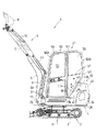
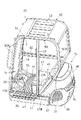
図1及び図2に示すように、本発明の実施形態にかかる旋回作業機1は、左右一対のクローラ走行体2を有する走行装置3の上部に、旋回ベアリングを介して上下方向の軸心X回りに回動自在に旋回台4を搭載したものとなっており、この旋回台4の前端部には作業装置5が設けられている。
作業装置5は、旋回台4の前端部に左右揺動自在に取り付けられたスイングブラケット12と、このスイングブラケット12に上下揺動自在に連結されたブーム6と、このブーム6の先端に上下揺動自在に連結されたアーム7と、このアーム7の先端に上下回動自在に連結されたバケット8とを有する掘削作業装置とされており、上記スイングブラケット12、ブーム6、アーム7およびバケット8は、それぞれ油圧シリンダ13、9、10、11によって作動するようになっている。なお、この作業装置5は、上記バケット8に代えてブレーカ等の他の機器を取り付けたものとしても良い。
Hereinafter, embodiments of the present invention will be described with reference to the drawings.
As shown in FIG. 1 and FIG. 2, the turning work machine 1 according to the embodiment of the present invention has an axial center X in the vertical direction via a turning bearing on an upper part of a
The
旋回台4の後部にはボンネット15が搭載され、このボンネット15の前側には、図4〜図6に示すように、運転席16や操縦フロア17、操縦レバー18、19、操縦ペダル20等を有する操縦部14が設けられている。この操縦部14は旋回台4上の前部に備えられたキャビン21によって包囲されている。
旋回台4は、平面視で左右側部及び前部が直線状に形成され、後端部が円弧状に形成されており、この後端部は走行装置3から後方に突出している。旋回軸心Xは、旋回台4の前後中央よりも前寄りに配設され、旋回台4を左右横向きに旋回したときにも、旋回台4の後端部が走行装置3から左右に突出するようになっている。運転席16は旋回軸心Xの後側であって、旋回台4の前後及び左右のほぼ中央部に配設されている。
A
The
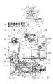
旋回台4の底部には板状のベースフレーム23が設けられ、このベースフレーム23の後端部にカウンタウエイト24、25が設けられ、ベースフレーム23の左右側部及び前部は、カバー体26により覆われている。なお、カウンタウエイト24、25は、左右中央に配設された主ウエイト24と、この主ウエイト24の左右両側に配設された側部ウエイト25とを有し、この側部ウエイト25は、旋回台4の後端左右隅部を保護するプロテクタとされている。
図4及び図7に示すように、ベースフレーム23の後部上面にはエンジン27が横置きに搭載され、エンジン27の左右一方(右側)に油圧ポンプ28が直結され、左右他方(左側)にファン29およびラジエータ30が配設されている。本実施形態では、吸い込み式のラジエータ30が採用されており、左右各側部ウエイト25には、外気の流入口31および吐き出し口32(図5及び図6参照)が形成されている。
A plate-
As shown in FIGS. 4 and 7, an
ベースフレーム23の前端部には、作業装置5を装着するための装着ブラケット34が前方突出状に設けられ、この装着ブラケット34からは左右一対の縦リブ35が後方広がり状(略ハの字状)に延設されている。ベースフレーム23の前後中途部には、左右方向に延びる区画壁36が立設され、この区画壁36の後側に前記エンジン27、油圧ポンプ28、ラジエータ30等が配設されている。
旋回軸心X位置にはスイベルジョイント39が配設され、その近傍に旋回モータ37が配設されており、操縦フロア17の前部左側には各油圧アクチュエータ13、9、10、11等を制御する制御弁38が配設されている。
A mounting
A swivel joint 39 is provided at the position of the turning axis X, and a turning
前記区画壁36の前側であってベースフレーム23の左右一側(左側)には作動油タンク41が配設され、左右他側(右側)には燃料タンク40が配設されている。区画壁36の後側にはサクションホース42が左右方向に配設され、このサクションホース42の一端が作動油タンク41の後部に接続され、他端が油圧ポンプ28に接続されている。作動油タンク41の前側には外置き型のリターンフィルタ(オイルフィルタ)43が配設されている。
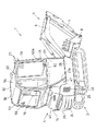
前記ボンネット15は、合成樹脂製又は金属製によって形成され、主としてエンジン27、ラジエータ30、油圧ポンプ28等の外方を覆うものであり、前部カバー45と、後部カバー46と、側部カバー47とから構成されている。前部カバー45及び後部カバー46は、旋回台4の略全体にわたる左右幅を有し、前部カバー45は旋回台4に固定され、後部カバー46はその前端上部を支点として上方に跳ね上げ可能とされた開閉カバーとなっている。
A
The
側部カバー47は、前部カバー45と後部カバー46との前後間に形成された略3角形の開口を塞ぐものとなっている。
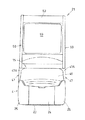
前記キャビン21は、旋回台4と左右略同幅に形成されており、この旋回台4の前端部からボンネット15上にかけてアーチ状(略U字状)に形成された主枠50を左右両側に備えている。左右主枠50の前後支柱50A、50Bの下端部同士は連結部材51により連結され、上部間には天井部52が設けられている。
キャビン21の左側面には、その前後中途部に中間支柱53が上下方向に設けられ、この中間支柱53の前側がキャビン21への出入り口54とされ、この出入り口54を開閉するドア55が中間支柱53に揺動自在に取り付けられている。
The side cover 47 closes a substantially triangular opening formed between the
The
On the left side of the
中間支柱53よりも後側には、上部にサイドガラス56が設けられ、下部に側部外装パネル57が設けられている。
キャビン21の前面及び後面にはそれぞれフロントガラス58、リヤガラス59が設けられている。
キャビン21の右側面では、主枠50の前後支柱50A、50B間に横梁部材60が架設され、この横梁部材60の上側にはサイドガラス56が設けられ、下側に外装パネル57が設けられている。
On the rear side of the
A
On the right side surface of the
このキャビン21の後部下端は、ボンネット15の前部カバー45上面に搭載されるようになっている。具体的には、図4〜図7に示すように、前部カバー45上面の裏側には支持板61が設けられ、この支持板61にマウントゴム等を介してキャビン21の後部が連結されるようになっている。。
支持板61は横長の帯板形状であり、その左右両側が脚部62を介してベースフレーム23又はウエイト24に支持されている。
また、支持板61には、ヒンジ部材63を介して後部カバー46の前上部が回動自在に支持されている。
The rear lower end of the
The
Further, the front upper portion of the
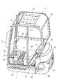
図3に示す背面視において、前記ボンネット15を構成する後部カバー46は、その側面形状が下方外広がり状の曲面となっている。一方側部カバー47は、図1及び図2に示すように側面視で略三角形状に形成されている。
図8〜図10に示すように、側部カバー47は、その前縁部に左右外側に張り出す膨出部47Aを備え、この膨出部47Aの後側は、後部カバー46の側面形状に沿うように下方外広がり状の曲面で形成された湾曲板部47Bとなっており、両者は一体に成型されている。膨出部47Aは、湾曲板部47Bの前縁から左右外側に屈曲し、さらに前側に屈曲し、さらに左右内側に屈曲することによって断面コ字形に形成されている。また、膨出部47Aはボンネット15の高さ全体に形成され、その上端面がボンネット15上面に位置している。
In the rear view shown in FIG. 3, the
As shown in FIGS. 8 to 10, the
ここで、上記膨出部47Aの外側面は、図3に示す背面視においてキャビン21の左右外側面と略連なるように略垂直な面とされ、図1及び図2に示す側面視において、キャビン21の後下部の傾斜(主枠50の後下部の傾斜)に連なるように前下がり状に傾斜している。このため、ボンネット15とキャビン21(特に、主枠50)との間で略連続的な外観を得られるようになっている
また、側部カバー47に膨出部47Aを形成することによりボンネット15側をキャビン21の形状に合わせるようになっているため、ボンネット15側面の曲面形状に応じてキャビン21の外装パネルを切り欠いたり、追加のパネル等を設ける必要もなく、また、ボンネット15の曲面とキャビン21との間でシールを施すことも避けることができるようになる。
Here, the outer surface of the bulging
図1、図5及び図6に示すように、前記前部カバー45の左右両側の前面45Aは、前下がり状に傾斜した平坦な面となっており、この面45Aによってキャビン21との間のシールがなされるようになっている。
具体的には、図1のA−A矢示部分を示す図8の如く、キャビン21の側部外装パネル57の内側には、左右内方に突出するシール受部材65が設けられ、このシール受部材65と前部カバー45の前面45Aとの間にシール材66が設けられ、両者間の水等の浸入が阻止されている。
As shown in FIGS. 1, 5 and 6, the
Specifically, as shown in FIG. 8 showing a portion indicated by arrows AA in FIG. 1, a
また、側部外装パネル57の後縁57Aは、シール受部材65と前部カバー45との隙間を左右外側から塞ぎ、さらに、前部カバー45の左右側面をも外側から覆う(外装パネル57とボンネット15側面とが左右方向にオーバーラップする)ように後方へ延設されている。
このため、シール材66は左右外方に露出せず、外観を損なうことがない。また、側部外装パネル57の後縁57Aと側部カバー47の前面(膨出部47Aの前面)との間には僅かに隙間67が設けられているが、この隙間67からシール材66へに至るまでの間には略L字状のラビリンス構造80が形成されているために、隙間67から水が浸入したとしても直接シール材66にかかることはほとんどなく、シール性を好適に維持できるようになっている。
Further, the
For this reason, the sealing
なお、側部外装パネル57の後縁57Aと側部カバー47の前面とは、図1に示すように側面視で僅かに湾曲した形状となっているが、両者の湾曲形状が若干不揃いであったとしても、両者間に隙間67を形成することにより吸収できるようになっている。
なお、上記側部カバー47及び前部カバー45とは別々の部材によって構成し、両者の間にはシール材を介在させているが、両者45、47を一体に形成することも可能である。
また、ボンネット15側のシール面45Aが平坦面となっているため、シール受部材65も平坦な面に形成することができ、両者の隙間を均一にすることが容易に可能となる。このため、確実なシールを施しやすくなっている。
Note that the
The
Further, since the
図4〜図6に示すように、前記操縦部14は、旋回台4の前部に操縦フロア17を設け、この操縦フロア17の前部側に走行用操作レバー18と操作ペダル20とを配置し、操縦フロア17の後側にはシート台68を介して運転席16が搭載され、この運転席16の左右両側には操作レバー19を有する操縦ボックス69が設けられている。上記操作レバー18や操作ペダル20が設けられている部分は操作部カバー70により覆われている。
前記操縦フロア17は、操作部カバー70を囲むかたちで運転席16の前側全体を覆うようになっており、その前端の左右両側は前上方に傾斜し、作業者の足置きとされている。また、この傾斜部分17Aの下方には上下に広い空間が形成され、該空間に制御弁38が配設されている。
As shown in FIGS. 4 to 6, the
The
操縦フロア17は、旋回台4に対してボルト等によって着脱自在に取り付けられ、取り外すことによって旋回台4内(カバー体26の内側)を露出可能となっている(図12参照)。
一方、旋回台4の左側に配設された作動油タンク41は、図4に示すようにその後部側がボンネット15の範囲に配設され、前部側がキャビン21の範囲に配設され、この作動油タンク41の前側に配設された外置きのリターンフィルタ43は、操縦フロア17の下方に配設されている。
The
On the other hand, the
そして、作動油タンク41及びリターンフィルタ43は、キャビン21の左側面に形成した出入り口54側に配設されていることから、図12の如く操縦フロア17を旋回台4から取り外すことによって、キャビン21の外側から出入り口54を介してリターンフィルタ43の点検等が可能となっている。
また、図13に示すように、ボンネット15の左側の側部カバー47を取り外すことによって、作動油タンク41の後部側が露出可能となっており、これによってサクションホース42との接続部やサクションフィルタの点検等が可能となっている。
And since the
Further, as shown in FIG. 13, the rear side of the
したがって、このような作動油タンク41やその付属機器(フィルタ)43の点検等は、旋回台4上にキャビン21が搭載されたままでこのキャビン21外側から容易に行えるようになっている。
図4、図6及び図7に示すように、燃料タンク40は旋回台4の右側に配設されており、この燃料タンク40は、作動油タンク41に比べてメンテナンス頻度が少ないために、キャビン21の反出入り口54側であってもさほど支障はない。また、作動油タンク41の左右反対側に燃料タンク40が配設されるために旋回台4の左右バランスを好適に図ることができるようになっいる。
Accordingly, such an inspection of the
As shown in FIGS. 4, 6, and 7, the
この燃料タンク40は、前後に長く左右に広幅に形成された主部40Aと、この主部40Aの後部下側から膨出する下膨出部40Bと、後部上側から上方に膨出してボンネット15内に収められる上膨出部40Cとを有し、旋回台4のカバー体26やボンネット15の側面範囲に収まる配置となり、このキャビン21を旋回台4から取り外すことなく、カバー体26やボンネット15の右側側部カバー47を取り外すことによって外側方に取り出すことができるようになっている。
燃料タンク40の上膨出部40Cには後上方に指向する給油筒72が突設され、この給油筒72には可撓性を有する延長管73の前端が接続され、延長管73の後端は支持板61の脚部62にブラケット等を介して支持されたL字状の給油管74の前端に接続されている。
The
A
この給油管74は、後部カバー46内に配設され、その下部側が前後方向の軸心回りに回動自在に支持されており、その給油口74Aを上向きとして後部カバー46内に収まった姿勢と、給油口74Aを左右外側に向けて後部カバー46の範囲から突出する姿勢とに姿勢変更可能であり、後部カバー46を開いて給油管の給油口74Aを外側に向けることによって、給油が容易に行えるようになっている。
本発明は、上記実施形態にのみ限定されるものではなく特許請求の範囲から逸脱しない範囲内において種々変更を加え得ることは勿論である。
The
The present invention is not limited to the above-described embodiments, and various modifications can be made without departing from the scope of the claims.
例えば、上記実施形態では、旋回作業機の形式として、旋回台4の後端が走行装置3の前後幅及び左右幅から突出するタイプ(所謂標準機)を示しているが、旋回台4の後端が走行装置3の前後幅及び左右幅から突出しないタイプ(所謂後方小旋回型)としたり、さらに掘削作業装置5の基部を運転席16の側方に支持したタイプ(超小旋回型)とすることができる。
キャビン21は、旋回台4の左右略全幅にわたるものとしているが、旋回台4が比較的大きくて運転席が旋回台4の左右一側に配置されている場合には、旋回台4よりも小幅のキャビン21を旋回台4の左右一側に偏心して設けてもよい。
For example, in the above-described embodiment, a type in which the rear end of the
The
1 旋回作業機
3 走行装置
4 旋回台
15 ボンネット
21 キャビン
45 前部カバー
45A 前面
47 側部カバー
47A 膨出部
57 側部外装パネル
57A 後縁
65 シール受部材
66 シール材
X 旋回軸心
DESCRIPTION OF SYMBOLS 1
Claims (4)
前記側部カバー(47)の後部に後部カバー(46)の側面形状に沿う弯曲板部(47B)を形成し、側部カバー(47)の前部に前記弯曲板部(47B)から外側に張り出してキャビン(21)の外側面に略連なる膨出部(47A)を形成しており、
前記膨出部(47A)は、弯曲板部(47B)の前縁から左右方向外側に屈曲し、さらに前側に屈曲してキャビン(21)の側部外装パネル(57)と略連なる外側面を形成していることを特徴とする旋回作業機。 A swivel base (4) is provided on the traveling device (3) so as to be rotatable around a vertical axis (X), a bonnet (15) is provided on the rear part of the swivel base (4), and a cabin ( 21), and the bonnet (15) includes a front cover (45) on which a rear lower portion of the cabin (21) is mounted, a rear cover (46) that can be opened and closed, and a side cover (47) therebetween. Have
A curved plate portion (47B) is formed along the side surface shape of the rear cover (46) at the rear portion of the side cover (47), and outward from the curved plate portion (47B) at the front portion of the side cover (47). Projecting and forming a bulging portion (47A) substantially continuous with the outer surface of the cabin (21),
The bulging portion (47A) is bent outward in the left-right direction from the front edge of the curved plate portion (47B), and further bent forward, and has an outer surface substantially continuous with the side exterior panel (57) of the cabin (21). A swivel working machine characterized by forming.
Priority Applications (1)
| Application Number | Priority Date | Filing Date | Title |
|---|---|---|---|
| JP2006233897A JP4101849B2 (en) | 2006-08-30 | 2006-08-30 | Swivel work machine |
Applications Claiming Priority (1)
| Application Number | Priority Date | Filing Date | Title |
|---|---|---|---|
| JP2006233897A JP4101849B2 (en) | 2006-08-30 | 2006-08-30 | Swivel work machine |
Related Parent Applications (1)
| Application Number | Title | Priority Date | Filing Date |
|---|---|---|---|
| JP2002278702A Division JP3947075B2 (en) | 2002-09-25 | 2002-09-25 | Swivel work machine |
Publications (2)
| Publication Number | Publication Date |
|---|---|
| JP2006316622A JP2006316622A (en) | 2006-11-24 |
| JP4101849B2 true JP4101849B2 (en) | 2008-06-18 |
Family
ID=37537529
Family Applications (1)
| Application Number | Title | Priority Date | Filing Date |
|---|---|---|---|
| JP2006233897A Expired - Fee Related JP4101849B2 (en) | 2006-08-30 | 2006-08-30 | Swivel work machine |
Country Status (1)
| Country | Link |
|---|---|
| JP (1) | JP4101849B2 (en) |
Families Citing this family (1)
| Publication number | Priority date | Publication date | Assignee | Title |
|---|---|---|---|---|
| JP6237735B2 (en) * | 2015-09-11 | 2017-11-29 | コベルコ建機株式会社 | Construction machine front guard structure |
-
2006
- 2006-08-30 JP JP2006233897A patent/JP4101849B2/en not_active Expired - Fee Related
Also Published As
| Publication number | Publication date |
|---|---|
| JP2006316622A (en) | 2006-11-24 |
Similar Documents
| Publication | Publication Date | Title |
|---|---|---|
| JP2009243119A (en) | Upper structure of working machine | |
| JP5254821B2 (en) | Swivel work machine | |
| JP2007092278A (en) | Upper structure of backhoe | |
| JP4101849B2 (en) | Swivel work machine | |
| JP4468872B2 (en) | Construction machinery | |
| JP3737998B2 (en) | Swivel work machine | |
| JP3947075B2 (en) | Swivel work machine | |
| JP6054581B2 (en) | Excavator | |
| JP6391522B2 (en) | Working machine | |
| JP3155463B2 (en) | Work machine support frame structure | |
| JP4246028B2 (en) | Engine room cover device | |
| JP3393987B2 (en) | Turning work machine | |
| JP4236550B2 (en) | Tank mounting structure for swivel work machine | |
| JP4614894B2 (en) | Work vehicle canopy | |
| JP4484573B2 (en) | Swivel work machine | |
| JP3471600B2 (en) | Turning work machine | |
| JP2001011898A (en) | Sunshade device for slewing work machine | |
| JP4515367B2 (en) | Backhoe | |
| JP3461440B2 (en) | Turning work machine | |
| JP2007092279A (en) | Back hoe | |
| JP3403630B2 (en) | Turning work machine | |
| JP2002155543A (en) | Turning work machine | |
| JP6081490B2 (en) | Hydraulic oil splash prevention device for construction machinery | |
| JP2000096612A (en) | Slewing working machine and cabin therefor | |
| JP2021169710A (en) | Working machine equipped with cab |
Legal Events
| Date | Code | Title | Description |
|---|---|---|---|
| A621 | Written request for application examination |
Free format text: JAPANESE INTERMEDIATE CODE: A621 Effective date: 20060830 |
|
| TRDD | Decision of grant or rejection written | ||
| A01 | Written decision to grant a patent or to grant a registration (utility model) |
Free format text: JAPANESE INTERMEDIATE CODE: A01 Effective date: 20080318 |
|
| A61 | First payment of annual fees (during grant procedure) |
Free format text: JAPANESE INTERMEDIATE CODE: A61 Effective date: 20080319 |
|
| FPAY | Renewal fee payment (event date is renewal date of database) |
Free format text: PAYMENT UNTIL: 20110328 Year of fee payment: 3 |
|
| R150 | Certificate of patent or registration of utility model |
Free format text: JAPANESE INTERMEDIATE CODE: R150 |
|
| FPAY | Renewal fee payment (event date is renewal date of database) |
Free format text: PAYMENT UNTIL: 20120328 Year of fee payment: 4 |
|
| FPAY | Renewal fee payment (event date is renewal date of database) |
Free format text: PAYMENT UNTIL: 20130328 Year of fee payment: 5 |
|
| FPAY | Renewal fee payment (event date is renewal date of database) |
Free format text: PAYMENT UNTIL: 20140328 Year of fee payment: 6 |
|
| LAPS | Cancellation because of no payment of annual fees |