JP4099933B2 - Wiring manufacturing method, wiring, and electro-optical device - Google Patents
Wiring manufacturing method, wiring, and electro-optical device Download PDFInfo
- Publication number
- JP4099933B2 JP4099933B2 JP2000195007A JP2000195007A JP4099933B2 JP 4099933 B2 JP4099933 B2 JP 4099933B2 JP 2000195007 A JP2000195007 A JP 2000195007A JP 2000195007 A JP2000195007 A JP 2000195007A JP 4099933 B2 JP4099933 B2 JP 4099933B2
- Authority
- JP
- Japan
- Prior art keywords
- film
- wiring
- group
- substrate
- manufacturing
- Prior art date
- Legal status (The legal status is an assumption and is not a legal conclusion. Google has not performed a legal analysis and makes no representation as to the accuracy of the status listed.)
- Expired - Fee Related
Links
Images


Landscapes
- Liquid Crystal (AREA)
- Electrodes Of Semiconductors (AREA)
- Drying Of Semiconductors (AREA)
- Internal Circuitry In Semiconductor Integrated Circuit Devices (AREA)
- Weting (AREA)
- Physical Deposition Of Substances That Are Components Of Semiconductor Devices (AREA)
- Thin Film Transistor (AREA)
Description
【0001】
【発明の属する技術分野】
本発明は、液晶装置等の電気光学装置や一般的な電子回路などに広く用いられる配線の製造方法、該配線及び該配線を用いた電気光学装置の技術分野に属する。
【0002】
【従来の技術】
従来、このような配線の材料としては、導電性や経済性に優れたAl(アルミニウム)膜からなる配線が広く用いられている。例えば、TFT(薄膜トランジスタ)基板、半導体基板等における各種信号線としての配線を製造する場合には、先ず基板上にAl膜をスパッタリングにより形成する。次に、レジストを用いたフォトリソグラフィ及びエッチングにより、Al膜をパターニングすることにより、所望のパターンを持つ配線が形成される。
【0003】
但し、Al膜の表面には、配線形成後に(例えば、TFT基板や半導体基板における素子形成用の高温や低温プロセス等で)曝される熱、湿気、水分等により、更には製品完成後における電流に起因したエレクトリックマイグレーション(EM)により、ヒロック、ボイド、マウスニップル、腐食等が発生しやすい。即ち、Al膜単体からなる配線の場合、これらの事象の発生により配線の断線やショートが起こりやすく、配線としての信頼性が低くなってしまう。
【0004】
そこで、例えば特開平7−58110号公報では、基板上で下層からTi(チタン)−TiN(窒化チタン)−AlSiCu(Al及びCuの合金シリサイド)−TiN(窒化チタン)−Ti(チタン)の5層に積層形成された多層構造の配線を形成する技術が提案されている。他方、Al膜の代りに、Alと他の金属元素との合金から配線を製造する技術も提案されている。
【0005】
【発明が解決しようとする課題】
しかしながら、上述した多層構造の配線を形成する技術によれば、エッチングによるパターニングの際に、Al膜用のエッチング液やエッチングガスでは、Al膜ではない他の膜(Ti膜等)をエッチングできない。従って、パターニングに関連して、製造工程の増加や複雑化及びコスト上昇を招いてしまうという問題点がある。更に、Al膜の比抵抗は低いため、配線の膜厚を固定して考えれば、概ね他の膜(Ti膜等)を積層するにつれて配線抵抗は上昇してしまう。これは特に、TFT基板上や半導体基板上における素子や配線の微細化を進める上で好ましいことではないという問題点もある。
【0006】
また、上述したAlと他の金属元素との合金から配線を製造する技術によれば、Al以外の元素の存在により、一般にAl単体からなる配線と比べて抵抗が大幅に上昇してしまい、配線としての本来の機能が顕著に低下してしまうという問題点がある。
【0007】
更に、このような多層構造を持つ配線やAlの合金からなる配線、或いはAl膜単体からなる配線を、データ線等の信号線として用いて液晶装置等の電気光学装置を構築した場合、製造工程や装置構成が複雑化してコスト上昇を招いたり、配線抵抗の上昇に起因したゴーストやクロストークなどによって表示画像の品位を劣化させたり、配線の信頼性低下によって電気光学装置全体としての装置信頼性を低下させてしまうという問題点もある。
【0008】
本発明は上述した問題点に鑑みなされたものであり、信頼性が高く且つ配線抵抗が低い配線を、比較的容易に製造することを可能ならしめる配線の製造方法、該配線及び該配線を備えた電気光学装置を提供することを課題とする。
【0009】
【課題を解決するための手段】
本発明の配線の製造方法は上記課題を解決するために、アルミニウムを主成分とする第1膜を形成する第1工程と、該第1膜上にIVA族、VA族又はVIA族に属する元素を含むと共に前記第1膜に比べて膜厚が薄く且つ前記第1膜上で平面的に見て部分的に相互に連結されているか或いは点在する多数の島状部分からなる不完全な第2膜をスパッタリングにより形成する第2工程と、前記第2膜上からのアルミニウム用のエッチングにより前記第2膜及び前記第1膜を一括してパターニングする第3工程とを含む。
【0010】
本発明の配線の製造方法によれば、先ず第1工程でアルミニウムを主成分とする第1膜を形成し、次に第2工程でこの第1膜上に第2膜を形成し、その後第3工程でこれらの第2膜及び第1膜をパターニングする。
【0011】
ここで、第2膜は、IVA族、VA族又はVIA族に属する元素を含むと共に第1膜に比べて膜厚が薄く、しかも第1膜上で平面的に見て、部分的に相互に連結されているか或いは点在する多数の島状部分からなる不完全な膜である。従って、第3工程のエッチングでパターニングする際に、第2膜上からのアルミニウム用のエッチング(即ち、リン酸、硝酸等を用いてのアルミニウム用のウエットエッチング、ドライエッチング又は両者の組み合わせ)により、エッチングで除去すべき平面領域(即ち、レジストが除去されて第2膜が露出した平面領域)においては、微視的に見て不完全な第2膜の島状部分の隙間から第1膜がエッチングされるので、第1膜の表面に形成された島状部分(即ち、第2膜)は第1膜と共に剥がれ落ちることになる。従って、第2膜自体がアルミニウム用のエッチングによってはエッチングが困難或いは実践上不可能な材質からなっていても、第2膜及び第1膜をアルミニウム用のエッチングにより、一括してパターニング可能となる。即ち、当該第2膜を追加的に形成しても、そのパターニングについては第1膜の一部として扱えるので(第1膜とは異なるエッチングガス或いはエッチング液を用いて第2膜を単独でパターニングする必要はないので)、製造工程上大変有利である。また、アルミニウム用のエッチングではエッチングされない或いはされ難い材質からなる第2膜で第1膜を覆うことにより、このエッチング時に第1膜に虫食い現象(即ち、レジストの縁付近でレジスト下にあって除去すべきでない部分が部分的に除去されてしまう現象)が発生するのを防ぐことも可能となる。以上のように本発明の配線の製造方法によれば、比較的簡単に配線を製造可能である。
【0012】
また、本発明の配線の製造方法によれば、第1膜の表面に第2膜を形成するので、配線形成後に(例えば、TFT基板や半導体基板における素子形成用の高温や低温プロセス等で)曝される熱、湿気、水分等により、更には製品完成後における電流に起因したエレクトリックマイグレーションにより、第1膜にヒロック、ボイド、マウスニップル、腐食等が発生するのを防止或いは低減となる。より具体的には、第1膜及び第2膜上に層間絶縁膜が形成される前に熱工程等で第1膜の表面部分が上方向へ微小に突出する現象であるヒロックを、第2膜で第1膜を上から覆って押さえつけることにより、防止或いは低減できる。従って、ヒロックに起因する上下配線間ショートを防止或いは低減可能となる。更に、製品完成後に電流を流した際(第1膜及び第2膜上に層間絶縁膜が形成された後)に、第1膜の表面部分がその界面に沿って横方向に広がる現象であるエレクトリックマイグレーションを、第2膜で第1膜を上から覆って固定することにより、防止或いは低減できる。従って、エレクトリックマイグレーションに起因する隣接配線間のショートを防止或いは低減可能となる。特に本発明の如く不完全な第2膜を形成した場合、ヒロックは微視的に見て第2膜の島状部分の間隙に発生するので、基板上における上下配線間隔などの実際の装置仕様に鑑みて実験的、経験的、理論的に或いはシミュレーションによって完成後のAl配線における断線不良の原因となる大きさのヒロックよりも小さなヒロックしか発生させない大きさの間隙を予め求めておき、当該配線を製造する際における第2工程で、このような間隙を持つように島状部分(第2膜)を形成すれば、ヒロックによる膜不良を極めて効果的に低減可能となる。尚、第2膜を厚く形成して完全な膜にしてしまったのでは、上述の如くアルミニウム用のエッチングで第2膜及び第1膜を一括してパターニングできなくなるので、このようにヒロックを防止可能な限度において、第2膜は薄く形成するのが好ましい。以上のように本発明によれば、Al膜単体からなる配線と比べて、ヒロック、エレクトリックマイグレーション等により配線の断線やショートが起こり難くなり、配線としての信頼性を高められる。
【0013】
更に、本発明の配線の製造方法によれば、第2膜は第1膜より薄く形成されるものであり、当該第2膜を極薄く形成しても、上述の如き配線の信頼性を高める機能は発揮される。このため、第2膜を極薄く形成することにより、第1膜たるAlを主成分としてなる第1膜からなる配線の抵抗を、配線の膜厚(合計膜厚)を固定して考えた場合、第2膜の存在により殆ど上昇させないことも可能となる(即ち、この観点からは、第2膜は薄い程好ましい)。例えば、Al膜単体から第1膜を形成すれば、第2膜を極薄く形成することにより、第2膜無しでAl膜単体からなる配線と比べて、配線抵抗を殆ど上昇させないで済む。以上のように本発明によれば、配線本来の機能を果たす上で極めて重要な配線の低抵抗化を図ることも可能である。
【0014】
加えて、本発明の配線の製造方法によれば、第2膜を適度な導電性を有する元素から形成することにより、第1膜が表面酸化して配線のコンタクト部分(電極パッド等)における表面抵抗が上昇するのを、第2膜で第1膜を覆うことにより防止或いは低減可能となる。
【0016】
以上詳細に説明したように、本発明によれば、信頼性が高く且つ配線抵抗が低い配線を、比較的容易に製造することが可能となる。
【0017】
本発明の配線の製造方法の一態様では、前記第1工程及び前記第2工程では、真空状態を維持しつつターゲットを交換しての連続スパッタリングにより前記第1膜及び前記第2膜を連続的に形成する。
【0018】
この態様によれば、真空状態を維持しつつ第1膜及び第2膜を連続的に形成するので、第1及び第2工程の間に、第1膜を大気に曝さないで済むので、第1膜の表面に酸化膜が形成されるのを防止できる。更に、第1及び第2工程の間に、第1膜を大気中の水分や湿気にも曝さないで済むので、該水分や湿気により第1膜の表面がダメージを受けるのを防止或いは低減可能となる。これらの結果、製造プロセスの中で、第1膜上の酸化膜を除去する工程が不要となったり、第1膜の表面状態を良好に保つことが容易となるため、一層有利となる。しかも、ターゲットを交換しての連続スパッタリングであれば、単一の真空チャンバを用いて、比較的容易に第1工程及び第2工程間で真空を破らないようにできる。
【0019】
本発明の配線の製造方法の他の態様では、前記第2膜は、20nm(ナノメータ)以下の膜厚を有する。
【0020】
この態様によれば、第2膜は、20nm以下の比較的薄い膜厚を有するので、上述の如く第3工程での一括エッチングを可能ならしめる島状部分であって且つヒロックが配線不良を引き起こす大きさへ成長するの阻止する程度の間隙を有する島状部分からなる不完全な膜を、スパッタリング等により比較的容易に形成できる。言い換えれば、第2工程で、20nm以下の膜厚の第2膜をスパッタリング等により形成することにより、本発明の如き多数の島状部分からなる不完全な第2膜を比較的容易に形成できる。
【0021】
本発明の配線の製造方法の他の態様では、前記第1膜は、Al(アルミニウム)単体、AlとCu(銅)、Ti(チタン)又はNb(ニオブ)との合金並びに該Al単体又は該合金のシリサイドのうちいずれか一つからなる。
【0022】
この態様によれば、例えばAl膜、Al+Si+Cu膜、Al+Cu膜、Al+Si膜、Al+Ti膜、Al+Nb膜等からなる第1膜であり、Al主成分の割合が多い配線が形成されるので、配線抵抗の低抵抗化を図ることが可能となる。また、Al単体膜を利用することで低抵抗化を比較的簡単に一層図ることができる。或いは、Al合金膜やそのシリサイド膜を利用することで、第1膜における耐湿性、耐水性を高めることができ、同時にヒロック、ボイド、マウスニップル、腐食等の発生を一層低減可能となる。
【0023】
本発明の配線の製造方法の他の態様では、前記第2膜は、前記IVA族に属する元素としてTi(チタン)、Zr(ジルコニウム)又はHf(ハフニウム)、前記VA族に属する元素としてV(バナジウム)、Nb(ニオブ)又はTa(タンタル)、若しくは前記VIA族に属する元素としてCr(クロム)、Mo(モリブデン)又はW(タングステン)を主成分とする。
【0024】
この態様によれば、第2膜の主成分として、各種元素を用いることが可能である。特に個々の配線として要求される性能及び用途並びに製造コスト等を勘案してこれらの元素の中から最適なものを選んで第2膜を形成すれば実用上大変有利である。尚、このような第2膜としては、単体金属から形成してもよいし、これらの合金又は混合でもよい。
【0025】
本発明の配線の製造方法の他の態様では、前記第1膜を、TFT基板上、半導体基板上又はマイクロマシン用基板上に形成する。
【0026】
この態様によれば、TFT基板上、半導体基板上又はマイクロマシン用基板上に本発明による配線を各種信号配線として形成することが可能となり、配線抵抗が低く且つ配線不良が低減された当該配線を採用することで、液晶装置等の電気光学装置などに好適に用いられ、装置信頼性が高く且つ高性能のTFTアレイ基板装置や半導体基板装置を比較的容易に製造可能となる。
【0027】
本発明の配線は上記課題を解決するために、アルミニウムを主成分とする第1膜と、該第1膜上に配置されており、IVA族、VA族又はVIA族に属する元素を含むと共に前記第1膜に比べて膜厚が薄く且つ前記第1膜上で平面的に見て部分的に相互に連結されているか或いは点在する多数の島状部分からなり、スパッタリングにより形成された不完全な第2膜とを備え、前記第1膜及び前記第2膜は、一括でパターニングされている。
【0028】
本発明の配線によれば、第2膜は、IVA族、VA族又はVIA族に属する元素を含むと共に第1膜に比べて膜厚が薄く、しかも第1膜上で平面的に見て、部分的に相互に連結されているか或いは点在する多数の島状部分からなる不完全な膜である。従って、第1膜におけるヒロック、ボイド、マウスニップル、腐食等の発生が第2膜の存在により製造工程中に防止或いは低減される分だけ、本発明の配線は製造当初から信頼性が高い。更に、このような第2膜は、製品完成後に配線における電流に起因したエレクトリックマイグレーションを防止又は低減するので、当該配線は、動作中に不良化する可能性が低くなり、その信頼性は非常に高くなる。しかも、第2膜を薄く形成すれば、上述の如く配線不良を低減しつつ、配線本来の機能を果たす上で極めて重要な配線の低抵抗化を図ることも可能である。加えて、第1膜が表面酸化して配線のコンタクト部分(電極パッド等)における表面抵抗が上昇することも、第2膜により防止或いは低減可能にされているので、良好なコンタクトを容易にとることも可能である。
【0030】
以上詳細に説明したように、本発明によれば、信頼性が高く且つ低抵抗の配線が実現される。
【0031】
本発明の配線の一態様では、前記第1膜と前記第2膜との間には、酸化膜が形成されていない。
【0032】
この態様によれば、第1膜上に酸化膜を介すること無く第2膜が形成されているので、上述の如き第2膜によりヒロックやエレクトリックマイグレーションを防止して配線の信頼性を高める効果が十分に発揮される。この結果、配線の信頼性が一層高められる。尚、このような配線は、上述した本発明の配線の製造方法の一態様における真空状態を維持しつつ第1膜及び第2膜を連続的に形成する方法の結果として製造可能である。
【0033】
本発明の配線の他の態様では、前記第2膜は、20nm(ナノメータ)以下の膜厚を有する。
【0034】
この態様によれば、第2膜は、20nm以下の比較的薄い膜厚を有するが、第1膜上に多数の島状部分として形成されているので、上述の如くヒロックやエレクトリックマイグレーションを防止可能であり、配線の信頼性を高められる。しかも、第1膜と第2膜との合計膜厚を固定して考えた場合、第2膜を薄く形成する分だけ、第1膜を厚くすることが可能となるので、基板上の合計膜厚の増大を避けつつ(且つ装置信頼性を高めつつ)配線の低抵抗化を図ることが可能となる。
【0035】
本発明の配線の他の態様では、前記第1膜は、Al単体、AlとCu、Ti又はNbとの合金並びに該Al単体又は該合金のシリサイドのうちいずれか一つからなる。
【0036】
この態様によれば、例えばAl膜、Al+Si+Cu膜、Al+Cu膜、Al+Si膜、Al+Ti膜、Al+Nb膜等からなる第1膜であり、Al主成分の割合が多い配線が形成されるので、配線抵抗の低抵抗化を図ることが可能となる。また、Al単体膜を利用することで低抵抗化を比較的簡単に一層図ることができる。或いは、Al合金膜又はそのシリサイド膜を利用することで、第1膜における耐湿性、耐水性を高めることができ、同時にヒロック、ボイド、マウスニップル、腐食等の発生を一層低減可能となる。
【0037】
本発明の配線の他の態様では、前記第2膜は、前記IVA族に属する元素としてTi、Zr又はHf、前記VA族に属する元素としてV、Nb又はTa、若しくは前記VIA族に属する元素としてCr、Mo又はWを主成分とする。
【0038】
この態様によれば、第2膜の主成分として、各種元素を用いることが可能である。尚、このような第2膜としては、単体金属から形成してもよいし、これらの合金又は混合でもよい。
【0039】
本発明の配線の他の態様では、前記第2膜上に絶縁膜が形成されている。
【0040】
この態様によれば、第2膜上には絶縁膜が形成されているので、その製造過程で第2膜を構成する多数の島状部分の間隙を介して成長しようとするヒロックが当該層間絶縁膜形成後に層間絶縁膜により押えられている分だけ、配線の信頼性が高められる。更に、製造完了後の使用時にも、第2膜に加えて層間絶縁膜により第1膜を上側から覆うことにより、配線の信頼性を更に高めることが可能となる。従って、第2膜をより薄く形成することも可能となる。
【0041】
本発明の配線の他の態様では、当該配線のコンタクト部分が、前記第2膜からなる。
【0042】
この態様によれば、配線のコンタクト部分は、Alを主成分とする第1膜からではなく、IVA族、VA族又はVIA族に属する元素を含む第2膜からなるので、コンタクト部分が第1膜からなる場合と比べて、表面酸化し難いコンタクト部分を構築することが可能となる。従って、当該配線と他の配線や素子との間で、良好なコンタクトを簡単にとることが可能となる。
【0043】
本発明の配線の他の態様では、前記第1膜は、TFT基板上、半導体基板上又はマイクロマシン用基板上に形成されている。
【0044】
この態様によれば、TFT基板上、半導体基板上又はマイクロマシン用基板上に本発明による配線が各種信号配線として形成されているので、液晶装置等の電気光学装置などに好適に用いられ、装置信頼性が高く且つ高性能のTFTアレイ基板装置や半導体基板装置を比較的容易に実現できる。
【0045】
本発明の電気光学装置は上記課題を解決するために、上述した本発明の配線(各種態様を含む)を信号線として備える。
【0046】
本発明の電気光学装置によれば、信頼性が高く且つ低抵抗の信号配線を備えるので、装置全体としても信頼性を高めることが可能であり、且つ高い性能を実現可能である。特に本発明の配線は、TFT基板上や半導体基板上における素子や配線の微細化を進めるのに役立つので、高精細度或いは高解像度の画像表示が可能な電気光学装置を実現可能となる。
【0047】
本発明のこのような作用及び他の利得は次に説明する実施の形態から明らかにされる。
【0048】
【発明の実施の形態】
以下、本発明の実施の形態を図面に基づいて説明する。
【0049】
(配線)
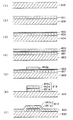
先ず、本発明の配線及びその製造方法の実施形態について、図1から図4を参照して説明する。図1は、本実施形態に係る配線の製造方法を各工程における断面図により順を追って示す工程図である。図2は、図1の工程(6)により形成される第2膜の二つの例の平面図であり、図3は、第2膜における膜厚とシート抵抗との関係を示す特性図である。図4は、図1の工程(6)の詳細を示す工程図である。
【0050】
図1において、先ず工程(1)では、マイクロマシン等の基板、半導体基板、TFT基板(例えば、石英基板、ガラス基板など)等の基板800が用意される。基板800が半導体基板であれば、基板800上に半導体素子を別途作り込むと共に本実施形態の製造方法により各種信号線を製造することにより、半導体基板装置を構築可能である。或いは、TFT基板であれば、基板800上にTFTを別途作り込むと共に本実施形態の製造方法により各種信号線を製造することにより、TFT基板装置を構築可能である。
【0051】
次に工程(2)では、真空チャンバ内でAlをターゲットとしてスパッタリングを行なうことにより、例えば膜厚数十nm〜数百nm程度の比較的厚い第1膜801をAl膜から形成する。より具体的な膜厚としては、装置仕様等に鑑み配線として必要な抵抗値を得るのに必要な膜厚とすればよい。
【0052】
但し、工程(2)で用いるターゲットとしては、Al単体の他、AlとCu、Ti又はNbとの合金若しくは該Al単体又は該合金のシリサイドでもよい。このようなターゲットに対応して、Al単体膜の他、Al+Si+Cu膜、Al+Cu膜、Al+Si膜、Al+Ti膜、Al+Nb膜等からなる第1膜801を形成可能である。
【0053】
次に工程(3)では、真空チャンバ内でTiをターゲットとしてスパッタリングを行い、数nm〜20nm程度の比較的薄い第2膜802を第1膜801上に形成する。このように20nm以下の膜厚を有する第2膜802を第1膜801上にスパッタリングで形成することにより、後に行われるエッチング工程(工程(6))で第1膜801及び第2膜802の一括エッチングを可能ならしめる島状部分であって且つヒロックが配線不良を引き起こす大きさへ成長するの阻止する程度の間隙を有する多数の島状部分からなる不完全な膜として、第2膜802を形成できる。
【0054】
但し、工程(3)で用いるターゲットとしては、IVA族、VA族又はVIA族に属する元素であればよく、Tiの他にも例えば、IVA族に属する元素としてZr又はHf、VA族に属する元素としてV、Nb又はTa、若しくはVIA族に属する元素としてCr、Mo又はWを主成分としていればよい。このようなターゲットに対応して、Ti膜の他、各種元素からなる第2膜802を形成可能である。また第2膜802は、このような単体金属から形成してもよいし、これらの合金又は混合でもよい。
【0055】
例えば図2(a)の平面図に示すように、このようにTi等から形成される第2膜802は、概ね相互に連結されている多数の島状部分からなるか、或いは、図2(b)の平面図に示すように、概ね点在する多数の島状部分からなる。一般には、スパッタリングの際には、先ず核となる微小な島状部分が第1膜801上に形成され、更にスパッタリングを続けることにより、この微小な島状部分が成長して、図2(b)に示す如き、概ね点在する多数の島状部分からなる第2膜802となる。更にスパッタリングを続けることにより、この点在する島状部分が成長して、図2(a)に示す如き、概ね相互に連結されている多数の島状部分からなる第2膜802となる。本実施形態では、第2膜802としては、例えば図2(a)又は図2(b)に示すような若しくはこれらの中間状態にある不完全な膜として形成される。いずれにせよ工程(3)では、図2(a)又は図2(b)に示したような間隙802cを有する不完全な膜に対応する膜厚となるようにスパッタリングを行う(即ち、間隙802cが存在しない完全な膜になる前の時点で、スパッタリングを停止する)。
【0056】
ここで第2膜802は、その膜厚とシート抵抗との間に、例えば図3の如き関係を持つ。
【0057】
図3において、膜厚が約20nm以上における特性曲線部分L1は、間隙802cがない完全な膜に対応しており、膜厚とシート抵抗とがほぼ反比例関係である。即ち、この特性曲線部分L1では、オームの法則に単純に従って断面積に反比例してシート抵抗が増加している。そして、膜厚約20nmのところに変極点P1が存在するが、この変極点P1における膜厚では、図2(a)に示した如き間隙802cが発生する。そして、膜厚が約20nm以下で約6nm以上における特性曲線部分L2は、間隙802cを有しており且つ相互に連結されている多数の島状部分からなる第2膜802に対応している。更に、膜厚約6nmのところに変極点P2が存在するが、この変極点P2における膜厚では、図2(b)に示したように間隙802cが大きくなって相互の連結が切れて点在する島状部分が発生する。そして、膜厚が約6nm以下における特性曲線部分L3は、間隙802cを有しており且つ点在する多数の島状部分からなる第2膜802に対応している。
【0058】
従って、実際に用いるスパッタリング装置により形成される第2膜802における図3の如き特性を予め実験的、経験的、論理的に或いはシミュレーションに求めることにより、本実施形態で形成すべき、第1膜801に比べて膜厚が薄く且つ第1膜801上で平面的に見て部分的に相互に連結されているか或いは点在する多数の島状部分からなる不完全な第2膜802に対応する膜厚を設定することが可能となる。そして、実際の製造プロセスにおいては、第2膜802の表面状態を一々検査する必要無しに、同一のスパッタリング装置或いは条件で、この設定膜厚の第2膜802を形成すれば、図2(a)又は図2(b)bの如き第2膜802が得られる。
【0059】
尚、上述の如き工程(2)及び工程(3)では、同一真空チャンバ内で、真空状態を維持しつつターゲットを交換しての連続スパッタリングにより、第1膜801及び第2膜802を連続的に形成するのが好ましい。このように形成すれば、工程(2)及び工程(3)の間に、第1膜801の表面を大気に曝さないで済むので、第1膜801の表面に酸化膜が形成されるのを防止できる。更に、工程(2)及び工程(3)の間に、第1膜801を大気中の水分や湿気にも曝さないで済むので、該水分や湿気により第1膜801の表面がダメージを受けるのを防止できる。
【0060】
次に図1に示す工程(4)では、フォトリソグラフィ用のレジストを第2膜802の全面に形成し、更に工程(5)で、所望の配線パターンを有するマスクを用いて或いは所望の配線パターンを描くレーザ光を用いてレジストを露光した後にその非硬化部分を除去することにより、製造すべき配線パターンを有するレジストパターン803aを第2膜802上に形成する。
【0061】
次に工程(6)では、このレジストパターン803aを介してエッチングを行う。このようなエッチングは、リン酸、硝酸等を用いた一般的なAl用のエッチング液又はエッチングガスを用いてのウエットエッチング又はドライエッチング若しくはこれらの組み合わせにより行う。
【0062】
ここで、図4を参照して、工程(6)におけるエッチングの詳細を説明する。図4の各断面図は、レジスト803aの縁付近における第1膜801及び第2膜802の断面を拡大して示したものである。
【0063】
図4において、先ず工程(6−1)では、矢印で示すAl用のエッチング液又はガス(リン酸、硝酸等)が、レジストで覆われていない第2膜802の表面に作用する。ここで、Al用のエッチングでは、Ti等からなる第2膜802自体は、殆どエッチングされないが、第2膜802を構成する多数の島状部分の間隙802cを介して、当該Al用のエッチングがAlを主成分とする第1膜801の表面に作用する。
【0064】
次に工程(6−2)では、このように間隙802cを介して作用するAl用のエッチング液又はガスにより、Alを主成分とする第1膜801の表面がエッチングされる。この際、第1膜801のエッチングが進むに連れて、第2膜802の島状部分の裏側(第1膜801側)にもエッチング液又はガスが回り込む。
【0065】
次に工程(6−3)では、第1膜801の表面のエッチングが進んで、第2膜802を構成する島状部分は、下地となっている第1膜801が除去されることにより剥がれ落ちる。即ち、結果的に、Al用のエッチングではエッチングされないTi等からなる第2膜802も、Al用のエッチングにより第1膜801と共に除去される。
【0066】
次に工程(6−4)では、レジスト803aの形成されていない領域における第2膜802及び第1膜801が完全に除去されて、レジスト803aの形成されている領域に、配線パターンを持つ第1膜801a及び第2膜802aが残される。
【0067】
最後に工程(6−5)では、レジスト803aを除去する。この結果として、上面に極薄い不完全な膜である第2膜802aが形成された第1膜801aからなる配線810が形成される。
【0068】
再び図1において、最後に工程(7)では、レジストパターン803aを除去した後に、配線810上及び基板800上の全面に、PSG(リンシリケートガラス)、BSG(ボロンシリケートガラス)等からなる絶縁膜820を形成して、基板800上における配線810の製造を終了する。
【0069】
以上図1から図4を参照して説明したように本実施形態によれば、第2膜802aは、IVA族、VA族又はVIA族に属する元素を含むと共に第1膜801aに比べて膜厚が薄く、しかも第1膜801a上で平面的に見て、部分的に相互に連結されているか或いは点在する多数の島状部分からなる不完全な膜である。従って、図1の工程(6)のエッチングでパターニングする際に、第2膜802上からのAl用のエッチングにより、エッチングで除去すべき平面領域においては、微視的に見て不完全な第2膜802の島状部分の隙間802cから第1膜801がエッチングされるので、第2膜802及び第1膜801を一括してパターニング可能となる。即ち、第2膜802aを追加的に形成しても、そのパターニングについては第1膜801aの一部として扱えるので、製造工程上大変有利である。
【0070】
また、図1の工程(6)におけるエッチング時には、レジスト803aの直下に第2膜802が形成されているので、レジスト803aの縁から下側にAl用のエッチング液又はガスが回りこむことに起因して第1膜801aの縁に発生する虫食いを効果的に防止できる。
【0071】
以上のように本実施形態の製造方法によれば、比較的簡単に配線810を製造できる。
【0072】
このような製造方法上の利点に加えて、本実施形態によれば、配線抵抗の上昇を殆ど招くことなく、製造過程におけるヒロックを防止すると共に製品完成後におけるエレクトリックマイグレーションを防止することにより配線としての信頼性を高める利点或いは不良率を低減する利点がある。本実施形態におけるこのような利点について図5から図8を参照して説明する。図5は、比較例及び本実施形態におけるヒロックの成長を図式的に示す断面図である。図6は、比較例及び本実施形態における配線の導通時間と累積不良率との関係を示す特性図である。図7は、本実施形態における第2層の膜厚と欠陥率及び必要なウエットエッチング時間との関係を示す特性図である。また図8は、第1膜の一例としてのAl及びTiの合金膜におけるTiの含有率と比抵抗との関係を示す特性図である。
【0073】
図5(a)に示す比較例では、第1膜801a上に第2膜802bを形成しないで配線を形成する例である。この例では、スパッタリングによる成膜当初は、表面状態は良好(平坦)であるが(図5(a)の上段)、その後、例えばTFT基板や半導体基板における素子形成用の高温や低温プロセス等で曝される熱、湿気、水分等により、微小なヒロック900’が発生する(図5(a)の中段)。そして更なる熱、湿気、水分等により、微小なヒロック900’が成長し、隣接するヒロック同士が結合して、巨大なヒロック900”となる(図5(a)の下段)。例えばこの場合、ヒロック900”の高さh1は、約0.5μm〜1μm程度にもなる。このような高さh1は、配線上の絶縁膜を破ってその上に配置された別の配線や素子と当該配線とがショートするに十分な高さである。
【0074】
これに対し図5(b)に示す本実施形態では、スパッタリングによる成膜当初は、表面状態は良好(平坦)であるが(図5(b)の上段)、その後、例えばTFT基板や半導体基板における素子形成用の高温や低温プロセス等で曝される熱、湿気、水分等により、第2膜802aの間隙802cをついて微小なヒロック900が発生する(図5(b)の中段)。そして更なる熱、湿気、水分等により、微小なヒロック900が成長しようとするが、上側から第2膜802aにより覆われているため、間隙802cの大きさに応じた高さh2にまでしか成長できない。更に、間隙802cを超えて隣接するヒロック同士が結合することも阻止される(図5(b)の下段)。例えばこの場合、ヒロック900の高さh2は、約0.2μm以下である。このような高さh2であれば、配線上の絶縁膜を破ってその上に配置された別の配線や素子と当該配線とがショートするに可能性は殆ど無い。このように本実施形態によれば、製造中(特に、配線810を覆う絶縁膜820ができるまでの間に)発生するヒロックに起因する上下配線間ショートを効果的に防止できる。
【0075】
更に、図5(a)に示す比較例の場合には、製品完成後における電流に起因したエレクトリックマイグレーションにより、第1膜801aにボイド、マウスニップル、腐食等が発生する。
【0076】
これに対し、本実施形態の配線の場合、製品完成後に電流を流した際に、第1膜801aの表面部分を第2膜802aで上から覆って固定することにより、製品完成後における電流に起因したエレクトリックマイグレーションを防止できる。このように本実施形態によれば、エレクトリックマイグレーションに起因する隣接配線間のショートを防止或いは低減可能となる。
【0077】
これらに加えて本実施形態では特に、第2膜802a上に絶縁膜820が形成されているので(図1の工程(7)参照)、第2膜802aを構成する多数の島状部分の間隙802cを介して成長しようとするヒロック900が絶縁膜820形成後に絶縁膜820により押えられている分だけ、配線810の信頼性を高められる。更に、製造完了後の使用時にも、第2膜802aに加えて絶縁膜820により第1膜801aを上側から固定することにより、エレクトリックマイグレーションを防止し得、配線810の信頼性を更に高められる。
【0078】
従って、図6の特性図に示すように、図5(a)に示した比較例の配線の場合には、通電前に既に上述のヒロック等に起因して不良率が高く、更に通電後も上述のマイグレーション等に起因して不良率が高い。これに対して、本実施形態の配線の場合には、通電前に既に上述の如くヒロックを低減することにより不良率が低くされ、更に通電後も上述のマイグレーションを低減することにより不良率が低い。図6の特性図における特性曲線の差Δは、上述の如き第2膜802aによるヒロック及びマイグレーションの防止効果によるものと考察される。
【0080】
更に図7の特性図に示すように、TiとAlとの合金の場合、Tiの含有率を0%から数%に増加させるだけで、比抵抗は顕著に増加する傾向を示す。従って、配線抵抗を低める観点からは、第1膜801aをAl単体膜から構成すること或いは他の元素との合金膜から形成する場合には当該他の元素の含有率を数%以下に抑えることが好ましい。特に本実施形態では、前述のように配線をAl単体膜から形成する際の問題点(配線がヒロック、マイグレーション、水分、湿気等による影響を受けやすいこと)は第2膜802aを設けることで解決しているため、第1膜802aをAl単体膜から構成しても何ら問題は無いので有利である。これに加えて上述した実施形態では、第2膜802aは第1膜801aと比べて極薄く形成されているので、配線810の抵抗を、配線の膜厚(合計膜厚)を固定して考えた場合、第2膜802aの存在により殆ど上昇させない点からも一層有利である。尚、図7に示したような傾向は、Tiに代えて、他のIVA族、VA族又はVIA族に属する元素とAlとの合金の場合にも同様である。
【0081】
尚、本実施形態では、配線810のコンタクト部分(即ち、電極パッド或いはボンディングパッド)は、第2膜802aからなる。従って、コンタクト部分が第1膜801aからなる場合と比べて、表面酸化し難いコンタクト部分とすることができ、配線810と他の配線や素子との間で、良好なコンタクトを簡単にとれる。
【0083】
(電気光学装置)
次に上述した実施形態に係る配線を備えた電気光学装置の実施形態について図8から図12を参照して説明する。本実施形態は、上述した実施形態に係る配線をTFTアレイ基板上のデータ線として備えたものであり、該TFTアレイ基板と対向基板とを対向配置して、両者間に液晶等の電気光学物質を挟持してなる電気光学装置に係る実施形態である。
【0084】
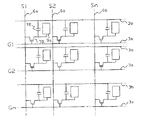
先ず図8から図10を参照して、本実施形態の電気光学装置の画像表示領域における構成についてその動作と共に説明する。ここに、図8は、電気光学装置の画像表示領域を構成するマトリクス状に形成された複数の画素における各種素子、配線等の等価回路である。図9は、データ線、走査線、画素電極等が形成されたTFTアレイ基板の相隣接する複数の画素群の平面図であり、図10は、図9のA−A'断面図である。尚、図10においては、各層や各部材を図面上で認識可能な程度の大きさとするため、各層や各部材毎に縮尺を異ならしめてある。
【0085】
図8において、本実施形態の電気光学装置では、その画像表示領域を構成するマトリクス状に形成された複数の画素は、画素電極9aと当該画素電極9aを制御するためのTFT30とがマトリクス状に複数形成されており、画像信号が供給されるデータ線6aが当該TFT30のソースに電気的に接続されている。また、TFT30のゲートに走査線3aが電気的に接続されており、所定のタイミングで、走査線3aにパルス的に走査信号G1、G2、…、Gmを、この順に線順次で印加するように構成されている。画素電極9aは、TFT30のドレインに電気的に接続されており、スイッチング素子であるTFT30を一定期間だけそのスイッチを閉じることにより、データ線6aから供給される画像信号S1、S2、…、Snを所定のタイミングで書き込む。画素電極9aを介して電気光学物質に書き込まれた所定レベルの画像信号S1、S2、…、Snは、対向基板(後述する)に形成された対向電極(後述する)との間で一定期間保持される。電気光学物質は、印加される電圧レベルにより分子集合の配向や秩序が変化することにより、光を変調し、階調表示を可能にする。ここで、保持された画像信号がリークするのを防ぐために、画素電極9aと対向電極との間に形成される電気光学物質容量と並列に蓄積容量70を付加する。
【0086】
図9において、本実施形態の電気光学装置においては、TFTアレイ基板上に、マトリクス状に複数の透明な画素電極9a(点線部9a'により輪郭が示されている)が設けられており、画素電極9aの縦横の境界に各々沿ってデータ線6a、走査線3a及び容量線3bが設けられている。データ線6aは、コンタクトホール5を介してポリシリコン膜等からなる半導体層1aのうち後述のソース領域に電気的接続されており、画素電極9aは、コンタクトホール8を介して半導体層1aのうち後述のドレイン領域に電気的接続されている。また、半導体層1aのうちチャネル領域(図中右下がりの斜線の領域)に対向するように走査線3aが配置されており、走査線3aはゲート電極として機能する。容量線3bは、走査線3aに沿ってほぼ直線状に伸びる本線部と、データ線6aと交差する箇所からデータ線6aに沿って前段側(図中、上向き)に突出した突出部とを有する。また、図中太線で示した矩形の島状領域には夫々、各TFTの少なくともチャネル領域をTFTアレイ基板側から見て一画素毎に夫々覆う位置に、島状の第1遮光膜11aが設けられている。
【0087】
次に図10の断面図に示すように、電気光学装置は、透明なTFTアレイ基板10と、これに対向配置される透明な対向基板20とを備えている。TFTアレイ基板10は、例えば石英基板からなり、対向基板20は、例えばガラス基板や石英基板からなる。TFTアレイ基板10には、画素電極9aが設けられており、その上側には、ラビング処理等の所定の配向処理が施された配向膜16が設けられている。画素電極9aは例えば、ITO膜(Indium Tin Oxide膜)などの透明導電性薄膜からなる。また配向膜16は例えば、ポリイミド薄膜などの有機薄膜からなる。他方、対向基板20には、その全面に渡って対向電極(共通電極)21が設けられており、その下側には、ラビング処理等の所定の配向処理が施された配向膜22が設けられている。TFTアレイ基板10には、図10に示すように、各画素電極9aに隣接する位置に、各画素電極9aをスイッチング制御する画素スイッチング用TFT30が設けられている。対向基板20には、更に図10に示すように、各画素の開口領域(即ち、画像表示領域内において実際に入射光が透過して表示に有効に寄与する領域)以外の領域に、第2遮光膜23が設けられている。
【0088】
このように構成され、画素電極9aと対向電極21とが対面するように配置されたTFTアレイ基板10と対向基板20との間には、後述のシール材(図11及び図12参照)により囲まれた空間に液晶等の電気光学物質が封入され、電気光学物質層50が形成される。電気光学物質層50は、画素電極9aからの電界が印加されていない状態で配向膜16及び22により所定の配向状態をとる。電気光学物質層50は、例えば一種又は数種類のネマティック液晶を混合した電気光学物質からなる。シール材は、TFT基板10及び対向基板20をそれらの周辺で貼り合わせるための、例えば光硬化性樹脂や熱硬化性樹脂からなる接着剤であり、両基板間の距離を所定値とするためのグラスファイバー或いはガラスビーズ等のスペーサが混入されている。
【0089】
図9及び図10において本実施の形態では、データ線6a、走査線3a及び容量線3b並びにTFT30を含む図9中右上がりの斜線が引かれた網目状の領域においては、TFTアレイ基板10が凹状に窪んでおり、画像表示領域の平坦化用の溝が形成されている。
【0090】
図10に示すように、画素スイッチング用TFT30に各々対向する位置においてTFTアレイ基板10と各画素スイッチング用TFT30との間には、一画素毎に島状に第1遮光膜11aが設けられている。第1遮光膜11aは、好ましくは不透明な高融点金属であるTi、Cr、W、Ta、Mo及びPbのうちの少なくとも一つを含む、金属単体、合金、金属シリサイド等から構成される。
【0091】
更に、第1遮光膜11aと複数の画素スイッチング用TFT30との間には、第1層間絶縁膜12が設けられている。第1層間絶縁膜12は、画素スイッチング用TFT30を構成する半導体層1aを第1遮光膜11aから電気的絶縁するために設けられるものである。更に、第1層間絶縁膜12は、TFTアレイ基板10の全面に形成されることにより、画素スイッチング用TFT30のための下地膜としての機能をも有する。
【0092】
本実施の形態では、ゲート絶縁膜2を走査線3aに対向する位置から延設して誘電体膜として用い、半導体層1aを延設して第1蓄積容量電極1fとし、更にこれらに対向する容量線3bの一部を第2蓄積容量電極とすることにより、蓄積容量70が構成されている。
【0093】
図10において、画素スイッチング用TFT30は、LDD(Lightly Doped Drain)構造を有しており、走査線3a、当該走査線3aからの電界によりチャネルが形成される半導体層1aのチャネル領域1a'、走査線3aと半導体層1aとを絶縁するゲート絶縁膜2、データ線6a、半導体層1aの低濃度ソース領域1b及び低濃度ドレイン領域1c、半導体層1aの高濃度ソース領域1d並びに高濃度ドレイン領域1eを備えている。高濃度ドレイン領域1eには、複数の画素電極9aのうちの対応する一つが接続されている。本実施の形態では特にデータ線6aは、Al等の低抵抗な金属膜や金属シリサイド等の合金膜などの遮光性の薄膜から構成されている。また、走査線3a、ゲート絶縁膜2及び第1層間絶縁膜12の上には、高濃度ソース領域1dへ通じるコンタクトホール5及び高濃度ドレイン領域1eへ通じるコンタクトホール8が各々形成された第2層間絶縁膜4が形成されている。更に、データ線6a及び第2層間絶縁膜4の上には、高濃度ドレイン領域1eへのコンタクトホール8が形成された第3層間絶縁膜7が形成されている。
【0094】
画素スイッチング用TFT30は、好ましくは上述のようにLDD構造を持つが、低濃度ソース領域1b及び低濃度ドレイン領域1cに不純物イオンの打ち込みを行わないオフセット構造を持ってよいし、走査線3aの一部であるゲート電極をマスクとして高濃度で不純物イオンを打ち込み、自己整合的に高濃度ソース及びドレイン領域を形成するセルフアライン型のTFTであってもよい。また本実施の形態では、画素スイッチング用TFT30のゲート電極をソース−ドレイン領域間に1個のみ配置したシングルゲート構造としたが、これらの間に2個以上のゲート電極を配置してもよい。この際、各々のゲート電極には同一の信号が印加されるようにする。
【0095】
次に図11及び図12を参照して、以上のように構成された電気光学装置の全体構成を説明する。尚、図11は、TFTアレイ基板10をその上に形成された各構成要素と共に対向基板20の側から見た平面図であり、図12は、対向基板20を含めて示す図11のH−H'断面図である。
【0096】
図11において、TFTアレイ基板10の上には、シール材52がその縁に沿って設けられており、その内側に並行して、例えば第2遮光膜23と同じ或いは異なる材料から成る額縁としての第3遮光膜53が設けられている。シール材52の外側の領域には、データ線駆動回路101及び外部回路接続端子102がTFTアレイ基板10の一辺に沿って設けられており、走査線駆動回路104が、この一辺に隣接する2辺に沿って設けられている。更にTFTアレイ基板10の残る一辺には、画像表示領域の両側に設けられた走査線駆動回路104間をつなぐための複数の配線105が設けられている。また、対向基板20のコーナー部の少なくとも1箇所においては、TFTアレイ基板10と対向基板20との間で電気的導通をとるための上下導通材106が設けられている。そして、図12に示すように、図11に示したシール材52とほぼ同じ輪郭を持つ対向基板20が当該シール材52によりTFTアレイ基板10に固着されている。
【0097】
以上図8から図12を参照して説明した電気光学装置の実施形態では、データ線駆動回路101及び走査線駆動回路104をTFTアレイ基板10の上に設ける代わりに、例えばTAB(テープオートメイテッドボンディング基板)上に実装された駆動用LSIに、TFTアレイ基板10の周辺部に設けられた異方性導電フィルムを介して電気的及び機械的に接続するようにしてもよい。また、本願発明をTFTアクティブマトリクス駆動方式以外の、TFD(薄膜ダイオード)アクティブマトリクス方式、パッシブマトリクス駆動方式などいずれの方式に適用しても高品位の画像表示が可能な電気光学装置を実現できる。更にまた、上述の電気光学装置では、対向基板20の外面及びTFTアレイ基板10の外面には各々、例えば、TN(Twisted Nematic)モード、VA(Vertically Aligned)モード、PDLC(Polymer Dispersed Liquid Crystal)モード等の動作モードや、ノーマリーホワイトモード/ノーマリーブラックモードの別に応じて、偏光フィルム、位相差フィルム、偏光板などが所定の方向で配置される。
【0098】
以上詳細に説明したように本実施形態の電気光学装置によれば、上述した実施形態に係る信頼性が高く且つ低抵抗の配線810をデータ線6aとして備えるので、装置全体としても信頼性が高く且つ高性能である。特に上述した実施形態に係る配線810は、配線の微細化を進めるのに役立つので、高精細度或いは高解像度の画像表示が可能となる。
【0099】
本発明は、上述した各実施形態に限られるものではなく、請求の範囲及び明細書全体から読み取れる発明の要旨或いは思想に反しない範囲で適宜変更可能であり、そのような変更を伴なう配線の製造方法、配線及び電気光学装置もまた本発明の技術的範囲に含まれるものである。
【0100】
【発明の効果】
以上詳細に説明したように本発明によれば、信頼性が高く且つ配線抵抗が低い配線を比較的容易に製造することが可能となる。また、このような配線を備えることにより装置信頼性が高く且つ高品位の画像表示が可能な電気光学装置を実現できる。
【図面の簡単な説明】
【図1】 本発明の実施形態に係る配線の製造方法を各工程における断面図により順を追って示す工程図である。
【図2】 図1の工程(6)により形成される第2膜の二つの例の平面図である。
【図3】 本実施形態の第2膜における膜厚とシート抵抗との関係を示す特性図である。
【図4】 図1の工程(6)の詳細を示す工程図である。
【図5】 比較例及び本実施形態におけるヒロックの成長を図式的に示す断面図である。
【図6】 比較例及び本実施形態における配線の導通時間と累積不良率との関係を示す特性図である。
【図7】 本実施形態の第1膜の一例としてのAl及びTiの合金膜におけるTiの含有率と比抵抗との関係を示す特性図である。
【図8】 本発明の電気光学装置の実施形態における画像表示領域を構成するマトリクス状の複数の画素に設けられた各種素子、配線等の等価回路である。
【図9】 図8の電気光学装置におけるデータ線、走査線、画素電極等が形成されたTFTアレイ基板の相隣接する複数の画素群の平面図である。
【図10】 図9のA−A'断面図である。
【図11】 本発明の電気光学装置の実施形態におけるTFTアレイ基板をその上に形成された各構成要素と共に対向基板の側から見た平面図である。
【図12】 図11のH−H'断面図である。
【符号の説明】
1a…半導体層
2…ゲート絶縁膜
3a…走査線
3b…容量線
5…コンタクトホール
6a…データ線
8…コンタクトホール
9a…画素電極
10…TFTアレイ基板
11a…第1遮光膜
20…対向基板
21…対向電極
23…第2遮光膜
30…画素スイッチング用TFT
50…電気光学物質層
52…シール材
70…蓄積容量
101…データ線駆動回路
104…走査線駆動回路
800…基板
801、801a…第1膜
802、802a…第2膜
803c…間隙
803、803a…レジスト
810…配線
820…絶縁膜[0001]
BACKGROUND OF THE INVENTION
The present invention belongs to the technical field of wiring manufacturing methods widely used in electro-optical devices such as liquid crystal devices and general electronic circuits, and the wiring and electro-optical devices using the wiring.
[0002]
[Prior art]
Conventionally, wiring made of an Al (aluminum) film having excellent conductivity and economy has been widely used as a material for such wiring. For example, when manufacturing wiring as various signal lines on a TFT (thin film transistor) substrate, a semiconductor substrate, etc., an Al film is first formed on the substrate by sputtering. Next, the Al film is patterned by photolithography and etching using a resist, thereby forming a wiring having a desired pattern.
[0003]
However, the surface of the Al film may be exposed to heat, moisture, moisture, etc. that are exposed after wiring formation (for example, in a high-temperature or low-temperature process for forming an element on a TFT substrate or a semiconductor substrate), and further after the product is completed. Due to electric migration (EM) due to hillocks, voids, mouth nipples, corrosion and the like are likely to occur. That is, in the case of a wiring composed of a single Al film, the occurrence of these events tends to cause a disconnection or a short circuit of the wiring, resulting in a low reliability of the wiring.
[0004]
Therefore, for example, in Japanese Patent Application Laid-Open No. 7-58110, Ti (titanium) -TiN (titanium nitride) -AlSiCu (Al and Cu alloy silicide) -TiN (titanium nitride) -Ti (titanium) 5 from the lower layer on the substrate. There has been proposed a technique for forming a wiring having a multilayer structure in which layers are stacked. On the other hand, a technique for manufacturing a wiring from an alloy of Al and another metal element instead of the Al film has been proposed.
[0005]
[Problems to be solved by the invention]
However, according to the above-described technique for forming a multilayer wiring, other films (such as a Ti film) that are not Al films cannot be etched with an etching solution or etching gas for an Al film during patterning by etching. Therefore, there is a problem that the manufacturing process is increased, complicated, and costs are increased in connection with patterning. Furthermore, since the specific resistance of the Al film is low, if the thickness of the wiring is fixed, the wiring resistance generally increases as another film (Ti film or the like) is laminated. In particular, this also has a problem that it is not preferable when the elements and wirings on the TFT substrate and the semiconductor substrate are miniaturized.
[0006]
In addition, according to the above-described technology for manufacturing a wiring from an alloy of Al and another metal element, the presence of an element other than Al generally causes a significant increase in resistance as compared with a wiring made of only Al. As a result, there is a problem that the original function is significantly reduced.
[0007]
Furthermore, when an electro-optical device such as a liquid crystal device is constructed using a wiring having such a multilayer structure, a wiring made of an Al alloy, or a wiring made of an Al film alone as a signal line such as a data line, a manufacturing process In addition, the device configuration becomes complicated and causes an increase in cost, the display image quality deteriorates due to ghost and crosstalk caused by an increase in wiring resistance, and the reliability of the electro-optical device as a whole due to a decrease in wiring reliability There is also a problem of lowering.
[0008]
The present invention has been made in view of the above-described problems, and includes a wiring manufacturing method that makes it possible to relatively easily manufacture a wiring having high reliability and low wiring resistance, the wiring, and the wiring. Another object is to provide an electro-optical device.
[0009]
[Means for Solving the Problems]
In order to solve the above problems, a method for manufacturing a wiring according to the present invention includes a first step of forming a first film mainly composed of aluminum, and an element belonging to the group IVA, VA or VIA on the first film. And has a thickness smaller than that of the first film and is partially connected to each other in plan view on the first film, or is incompletely formed of a large number of island-shaped portions scattered. 2 membranesBy sputteringA second step of forming, and a third step of collectively patterning the second film and the first film by etching for aluminum from the second film.
[0010]
According to the method for manufacturing a wiring of the present invention, first, a first film containing aluminum as a main component is formed in a first process, and then a second film is formed on the first film in a second process. These second and first films are patterned in three steps.
[0011]
Here, the second film includes an element belonging to the IVA group, the VA group, or the VIA group, is thinner than the first film, and is partially mutually mutually viewed in plan view on the first film. It is an incomplete film consisting of a number of islands connected or interspersed. Therefore, when patterning by etching in the third step, by etching for aluminum from the second film (that is, wet etching for aluminum using phosphoric acid, nitric acid, etc., dry etching or a combination of both), In the planar region to be removed by etching (that is, the planar region where the resist is removed and the second film is exposed), the first film is removed from the gap between the island-shaped portions of the second film that is microscopically incomplete. Since the etching is performed, the island-like portion (that is, the second film) formed on the surface of the first film is peeled off together with the first film. Therefore, even if the second film itself is made of a material that is difficult or practically impossible to etch by aluminum etching, the second film and the first film can be collectively patterned by etching for aluminum. . That is, even if the second film is additionally formed, the patterning can be handled as a part of the first film (the second film is patterned by using an etching gas or an etchant different from the first film). This is very advantageous in the manufacturing process. In addition, by covering the first film with a second film made of a material that is not etched or difficult to be etched by aluminum etching, the first film is removed by worm-eating phenomenon (that is, it is removed under the resist near the edge of the resist). It is also possible to prevent the occurrence of a phenomenon in which a portion that should not be removed is partially removed. As described above, according to the wiring manufacturing method of the present invention, wiring can be manufactured relatively easily.
[0012]
In addition, according to the wiring manufacturing method of the present invention, since the second film is formed on the surface of the first film, after the wiring is formed (for example, in a high temperature or low temperature process for forming an element in a TFT substrate or a semiconductor substrate). It is possible to prevent or reduce the occurrence of hillocks, voids, mouth nipples, corrosion, and the like in the first film due to the heat, moisture, moisture, etc. that are exposed, and also due to electric migration caused by the current after the product is completed. More specifically, the hillock, which is a phenomenon in which the surface portion of the first film slightly protrudes upward in a thermal process or the like before the interlayer insulating film is formed on the first film and the second film, By covering and pressing the first film with the film from above, it can be prevented or reduced. Therefore, it is possible to prevent or reduce a short circuit between the upper and lower wirings due to hillocks. Furthermore, when a current is passed after the product is completed (after an interlayer insulating film is formed on the first film and the second film), the surface portion of the first film spreads laterally along the interface. Electric migration can be prevented or reduced by covering and fixing the first film with the second film. Therefore, it is possible to prevent or reduce a short circuit between adjacent wirings due to electric migration. In particular, when an incomplete second film is formed as in the present invention, hillocks are generated microscopically in the gaps between the island-shaped portions of the second film. In view of the above, a gap having a size that generates only a hillock smaller than a hillock of a size that causes a disconnection failure in an Al wiring after completion is experimentally, empirically, theoretically or simulated, and the wiring If the island-shaped portion (second film) is formed so as to have such a gap in the second step when manufacturing the film, it is possible to extremely effectively reduce film defects due to hillocks. If the second film is formed thick to be a complete film, the second film and the first film cannot be patterned at once by etching for aluminum as described above, thus preventing hillocks in this way. It is preferable to form the second film as thin as possible. As described above, according to the present invention, the disconnection or short-circuit of the wiring is less likely to occur due to hillocks, electric migration, or the like as compared with the wiring made of a single Al film, and the reliability as the wiring can be improved.
[0013]
Further, according to the wiring manufacturing method of the present invention, the second film is formed thinner than the first film, and even if the second film is formed extremely thin, the reliability of the wiring as described above is improved. Function is demonstrated. Therefore, when the second film is formed to be extremely thin, the resistance of the wiring composed of the first film mainly composed of Al as the first film is considered with the wiring film thickness (total film thickness) fixed. It is also possible to hardly raise the film due to the presence of the second film (that is, the thinner the second film is, from this point of view). For example, if the first film is formed from a single Al film, the wiring resistance can be hardly increased by forming the second film to be extremely thin, as compared to a wiring made from a single Al film without the second film. As described above, according to the present invention, it is possible to reduce the resistance of the wiring, which is extremely important for achieving the original function of the wiring.
[0014]
In addition, according to the wiring manufacturing method of the present invention, the second film is formed from an element having appropriate conductivity, so that the surface of the first film is oxidized and the surface of the wiring contact portion (electrode pad or the like) is formed. The increase in resistance can be prevented or reduced by covering the first film with the second film.
[0016]
As described above in detail, according to the present invention, it is possible to relatively easily manufacture wiring having high reliability and low wiring resistance.
[0017]
In one aspect of the wiring manufacturing method of the present invention, in the first step and the second step, the first film and the second film are continuously formed by continuous sputtering while maintaining a vacuum state while maintaining the vacuum state. To form.
[0018]
According to this aspect, since the first film and the second film are continuously formed while maintaining the vacuum state, it is not necessary to expose the first film to the atmosphere during the first and second steps. An oxide film can be prevented from being formed on the surface of one film. Further, since the first film does not need to be exposed to moisture or moisture in the atmosphere during the first and second steps, the surface of the first film can be prevented or reduced from being damaged by the moisture or moisture. It becomes. As a result, a step of removing the oxide film on the first film becomes unnecessary in the manufacturing process, and it becomes easy to keep the surface state of the first film in a favorable state, which is further advantageous. Moreover, in the case of continuous sputtering with the target changed, a single vacuum chamber can be used so that the vacuum is not easily broken between the first step and the second step.
[0019]
In another aspect of the wiring manufacturing method of the present invention, the second film has a film thickness of 20 nm (nanometer) or less.
[0020]
According to this aspect, since the second film has a relatively thin film thickness of 20 nm or less, it is an island-like portion that enables collective etching in the third process as described above, and hillocks cause wiring defects. An incomplete film composed of island-like portions having gaps that prevent growth to a size can be formed relatively easily by sputtering or the like. In other words, in the second step, the second film having a thickness of 20 nm or less is formed by sputtering or the like, whereby the incomplete second film made up of a number of island portions as in the present invention can be formed relatively easily. .
[0021]
In another aspect of the method for manufacturing a wiring according to the present invention, the first film is made of Al (aluminum) alone, an alloy of Al and Cu (copper), Ti (titanium) or Nb (niobium), and the Al alone or It consists of any one of alloy silicides.
[0022]
According to this aspect, the first film made of, for example, an Al film, an Al + Si + Cu film, an Al + Cu film, an Al + Si film, an Al + Ti film, an Al + Nb film, or the like is formed. It is possible to reduce the resistance. In addition, the use of an Al single film makes it possible to further reduce the resistance relatively easily. Alternatively, by using the Al alloy film or its silicide film, the moisture resistance and water resistance of the first film can be increased, and at the same time, the occurrence of hillocks, voids, mouth nipples, corrosion, etc. can be further reduced.
[0023]
In another aspect of the method for manufacturing a wiring according to the present invention, the second film includes Ti (titanium), Zr (zirconium) or Hf (hafnium) as an element belonging to the IVA group, and V ( Vanadium), Nb (niobium), Ta (tantalum), or Cr (chromium), Mo (molybdenum), or W (tungsten) as the main element belonging to the VIA group.
[0024]
According to this aspect, various elements can be used as the main component of the second film. In particular, it is practically advantageous if the second film is formed by selecting an optimum one of these elements in consideration of the performance and application required for each wiring and the manufacturing cost. Such a second film may be formed of a single metal, or an alloy or a mixture thereof.
[0025]
In another aspect of the wiring manufacturing method of the present invention, the first film is formed on a TFT substrate, a semiconductor substrate, or a micromachine substrate.
[0026]
According to this aspect, the wiring according to the present invention can be formed as various signal wirings on a TFT substrate, a semiconductor substrate, or a micromachine substrate, and the wiring with low wiring resistance and reduced wiring defects is employed. As a result, the TFT array substrate device and the semiconductor substrate device which are suitably used for an electro-optical device such as a liquid crystal device and have high device reliability and high performance can be manufactured relatively easily.
[0027]
In order to solve the above problems, the wiring of the present invention is arranged on the first film mainly composed of aluminum and the first film, and includes an element belonging to the IVA group, the VA group, or the VIA group, and Compared to the first film, the film thickness is small, and the first film is made up of a number of island-like parts that are partially interconnected or scattered in plan view.Formed by sputteringWith an incomplete second membraneThe first film and the second film are patterned at once.
[0028]
According to the wiring of the present invention, the second film contains an element belonging to the IVA group, VA group or VIA group, and has a smaller film thickness than the first film, and when viewed in plan on the first film, It is an incomplete film consisting of a number of islands that are partially interconnected or interspersed. Therefore, the wiring according to the present invention is highly reliable from the beginning of manufacture because the occurrence of hillocks, voids, mouth nipples, corrosion, and the like in the first film is prevented or reduced during the manufacturing process due to the presence of the second film. Furthermore, since such a second film prevents or reduces electric migration due to current in the wiring after the product is completed, the wiring is less likely to become defective during operation, and its reliability is very high. Get higher. In addition, if the second film is formed thin, it is possible to reduce the resistance of the wiring, which is extremely important in fulfilling the original function of the wiring while reducing the wiring defects as described above. In addition, it is possible to prevent or reduce the surface resistance at the contact portion (electrode pad or the like) of the wiring due to the surface oxidation of the first film because it can be prevented or reduced by the second film. It is also possible.
[0030]
As described above in detail, according to the present invention, a highly reliable and low resistance wiring is realized.
[0031]
In one aspect of the wiring of the present invention, no oxide film is formed between the first film and the second film.
[0032]
According to this aspect, since the second film is formed on the first film without an oxide film, the second film as described above has the effect of preventing hillocks and electric migration and improving the reliability of the wiring. It is fully demonstrated. As a result, the reliability of the wiring is further enhanced. Such a wiring can be manufactured as a result of the method of continuously forming the first film and the second film while maintaining the vacuum state in the above-described aspect of the manufacturing method of the wiring of the present invention.
[0033]
In another aspect of the wiring of the present invention, the second film has a thickness of 20 nm (nanometer) or less.
[0034]
According to this aspect, the second film has a relatively thin film thickness of 20 nm or less, but is formed as a large number of island-shaped portions on the first film, so that hillocks and electric migration can be prevented as described above. Therefore, the reliability of wiring can be improved. In addition, when the total film thickness of the first film and the second film is fixed, the first film can be made thicker as much as the second film is formed. It is possible to reduce the resistance of the wiring while avoiding the increase in thickness (and improving the device reliability).
[0035]
In another aspect of the wiring of the present invention, the first film is made of any one of Al alone, an alloy of Al and Cu, Ti or Nb, and a silicide of the Al alone or the alloy.
[0036]
According to this aspect, the first film made of, for example, an Al film, an Al + Si + Cu film, an Al + Cu film, an Al + Si film, an Al + Ti film, an Al + Nb film, or the like is formed. It is possible to reduce the resistance. In addition, the use of an Al single film makes it possible to further reduce the resistance relatively easily. Alternatively, by using the Al alloy film or its silicide film, the moisture resistance and water resistance of the first film can be increased, and at the same time, the occurrence of hillocks, voids, mouth nipples, corrosion, etc. can be further reduced.
[0037]
In another aspect of the wiring of the present invention, the second film may be Ti, Zr or Hf as an element belonging to the IVA group, V, Nb or Ta as an element belonging to the VA group, or an element belonging to the VIA group. The main component is Cr, Mo or W.
[0038]
According to this aspect, various elements can be used as the main component of the second film. Such a second film may be formed of a single metal, or an alloy or a mixture thereof.
[0039]
In another aspect of the wiring of the present invention, an insulating film is formed on the second film.
[0040]
According to this aspect, since the insulating film is formed on the second film, hillocks that are to be grown through the gaps of the many island-shaped portions constituting the second film in the manufacturing process are affected by the interlayer insulation. The reliability of the wiring is increased by the amount that is held down by the interlayer insulating film after the film formation. Furthermore, even when the device is used after completion of manufacturing, it is possible to further improve the reliability of the wiring by covering the first film from the upper side with the interlayer insulating film in addition to the second film. Accordingly, the second film can be formed thinner.
[0041]
In another aspect of the wiring of the present invention, a contact portion of the wiring is made of the second film.
[0042]
According to this aspect, the contact portion of the wiring is not made of the first film containing Al as a main component, but is made of the second film containing an element belonging to the IVA group, the VA group, or the VIA group. Compared to the case of a film, it is possible to construct a contact portion that is less likely to be surface oxidized. Therefore, it is possible to easily make a good contact between the wiring and another wiring or element.
[0043]
In another aspect of the wiring of the present invention, the first film is formed on a TFT substrate, a semiconductor substrate, or a micromachine substrate.
[0044]
According to this aspect, since the wiring according to the present invention is formed as various signal wirings on the TFT substrate, the semiconductor substrate, or the micromachine substrate, it is preferably used for an electro-optical device such as a liquid crystal device, and the device reliability. A high-performance and high-performance TFT array substrate device or semiconductor substrate device can be realized relatively easily.
[0045]
In order to solve the above-described problems, the electro-optical device of the present invention includes the above-described wiring (including various aspects) of the present invention as a signal line.
[0046]
According to the electro-optical device of the present invention, since the signal wiring having high reliability and low resistance is provided, the reliability of the entire device can be improved and high performance can be realized. In particular, the wiring according to the present invention is useful for advancing the miniaturization of elements and wiring on a TFT substrate or a semiconductor substrate, so that an electro-optical device capable of displaying an image with high definition or high resolution can be realized.
[0047]
Such an operation and other advantages of the present invention will become apparent from the embodiments described below.
[0048]
DETAILED DESCRIPTION OF THE INVENTION
Hereinafter, embodiments of the present invention will be described with reference to the drawings.
[0049]
(wiring)
First, an embodiment of a wiring and a manufacturing method thereof according to the present invention will be described with reference to FIGS. FIG. 1 is a process diagram illustrating the wiring manufacturing method according to the present embodiment step by step with reference to cross-sectional views in each process. FIG. 2 is a plan view of two examples of the second film formed by the step (6) of FIG. 1, and FIG. 3 is a characteristic diagram showing the relationship between the film thickness and the sheet resistance in the second film. . FIG. 4 is a process diagram showing details of the process (6) of FIG.
[0050]
In FIG. 1, first, in step (1), a
[0051]
Next, in step (2), sputtering is performed using Al as a target in a vacuum chamber, thereby forming a relatively thick
[0052]
However, the target used in the step (2) may be Al alone, an alloy of Al and Cu, Ti, or Nb, or the Al alone or a silicide of the alloy. In response to such a target, a
[0053]
Next, in step (3), sputtering is performed using Ti as a target in a vacuum chamber, and a relatively thin
[0054]
However, the target used in step (3) may be any element belonging to Group IVA, VA or VIA. For example, in addition to Ti, elements belonging to Group IVA include Zr, Hf, and elements belonging to Group VA. As an element belonging to V, Nb or Ta or VIA group, Cr, Mo or W may be used as a main component. In response to such a target, the
[0055]
For example, as shown in the plan view of FIG. 2A, the
[0056]
Here, the
[0057]
In FIG. 3, the characteristic curve portion L1 when the film thickness is about 20 nm or more corresponds to a complete film without the
[0058]
Therefore, the first film to be formed in the present embodiment is obtained by previously obtaining the characteristics as shown in FIG. 3 in the
[0059]
In steps (2) and (3) as described above, the
[0060]
Next, in step (4) shown in FIG. 1, a photolithography resist is formed on the entire surface of the
[0061]
Next, in step (6), etching is performed through this resist
[0062]
Here, with reference to FIG. 4, the detail of the etching in a process (6) is demonstrated. Each cross-sectional view in FIG. 4 shows an enlarged cross section of the
[0063]
In FIG. 4, first, in step (6-1), an Al etching solution or gas (phosphoric acid, nitric acid, etc.) indicated by an arrow acts on the surface of the
[0064]
Next, in step (6-2), the surface of the
[0065]
Next, in the step (6-3), the etching of the surface of the
[0066]
Next, in step (6-4), the
[0067]
Finally, in step (6-5), the resist 803a is removed. As a result, a
[0068]
In FIG. 1 again, in the last step (7), after removing the resist
[0069]
As described above with reference to FIGS. 1 to 4, according to the present embodiment, the
[0070]
Further, at the time of etching in the step (6) of FIG. 1, since the
[0071]
As described above, according to the manufacturing method of the present embodiment, the
[0072]
In addition to the advantages in the manufacturing method, according to the present embodiment, the wiring resistance is hardly increased, and hillocks in the manufacturing process are prevented and electric migration after the product is completed is prevented. There is an advantage of improving the reliability or reducing the defect rate. Such advantages in the present embodiment will be described with reference to FIGS. FIG. 5 is a sectional view schematically showing the growth of hillocks in the comparative example and this embodiment. FIG. 6 is a characteristic diagram showing the relationship between the wiring conduction time and the cumulative failure rate in the comparative example and this embodiment. FIG. 7 is a characteristic diagram showing the relationship between the film thickness of the second layer, the defect rate, and the required wet etching time in the present embodiment. FIG. 8 is a characteristic diagram showing the relationship between the Ti content and the specific resistance in an alloy film of Al and Ti as an example of the first film.
[0073]
The comparative example shown in FIG. 5A is an example in which the wiring is formed without forming the second film 802b on the
[0074]
On the other hand, in the present embodiment shown in FIG. 5B, the surface state is good (flat) at the beginning of film formation by sputtering (upper stage in FIG. 5B), but after that, for example, a TFT substrate or a semiconductor substrate Due to heat, moisture, moisture, and the like that are exposed in a high-temperature or low-temperature process for forming an element, a
[0075]
Furthermore, in the case of the comparative example shown in FIG. 5A, voids, mouth nipples, corrosion, and the like are generated in the
[0076]
On the other hand, in the case of the wiring according to the present embodiment, when a current is passed after the product is completed, the surface portion of the
[0077]
In addition to these, in this embodiment, since the insulating
[0078]
Accordingly, as shown in the characteristic diagram of FIG. 6, in the case of the comparative example wiring shown in FIG. 5A, the defect rate is already high before the energization due to the above-mentioned hillocks, etc. The defect rate is high due to the migration described above. On the other hand, in the case of the wiring according to the present embodiment, the defect rate is lowered by reducing the hillock as described above before energization, and the defect rate is lowered by reducing the migration after energization. . The difference Δ between the characteristic curves in the characteristic diagram of FIG. 6 is considered to be due to the effect of preventing hillocks and migration by the
[0080]
Further figure7As shown in the characteristic diagram, in the case of an alloy of Ti and Al, the specific resistance tends to increase remarkably only by increasing the Ti content from 0% to several percent. Therefore, from the viewpoint of reducing the wiring resistance, when the
[0081]
In the present embodiment, the contact portion (that is, electrode pad or bonding pad) of the
[0083]
(Electro-optical device)
Next, an embodiment of an electro-optical device including the wiring according to the above-described embodiment will be described.8From figure12Will be described with reference to FIG. In the present embodiment, the wiring according to the above-described embodiment is provided as a data line on the TFT array substrate. The TFT array substrate and the counter substrate are arranged to face each other, and an electro-optical material such as a liquid crystal is interposed between the two. 1 is an embodiment according to an electro-optical device formed by sandwiching an electrode.
[0084]
First figure8From figure10The configuration of the electro-optical device of the present embodiment in the image display area will be described together with its operation. Here, figure8These are equivalent circuits such as various elements and wirings in a plurality of pixels formed in a matrix that constitutes an image display region of the electro-optical device. Figure9These are plan views of a plurality of pixel groups adjacent to each other on a TFT array substrate on which data lines, scanning lines, pixel electrodes, etc. are formed.10The figure9It is AA 'sectional drawing. The figure10In order to make each layer and each member large enough to be recognized on the drawing, the scale is different for each layer and each member.
[0085]
Figure8In the electro-optical device according to the present embodiment, the plurality of pixels formed in a matrix configuration that forms the image display region includes a plurality of
[0086]
Figure9In the electro-optical device of this embodiment, a plurality of
[0087]
Next figure10As shown in FIG. 1, the electro-optical device includes a transparent
[0088]
Between the
[0089]
Figure9And figure10In the present embodiment, the
[0090]
Figure10As shown in FIG. 3, the first light-shielding film 11a is provided in an island shape for each pixel between the
[0091]
Further, a first interlayer insulating film 12 is provided between the first light shielding film 11 a and the plurality of
[0092]
In the present embodiment, the
[0093]
Figure10The
[0094]
The
[0095]
Next figure11And figure12The overall configuration of the electro-optical device configured as described above will be described with reference to FIG. The figure11These are the top views which looked at
[0096]
Figure113, a sealing
[0097]
Figure above8From figure12In the embodiment of the electro-optical device described with reference to FIG. 5, instead of providing the data line driving
[0098]
As described above in detail, according to the electro-optical device of the present embodiment, since the highly reliable and low resistance wiring 810 according to the above-described embodiment is provided as the
[0099]
The present invention is not limited to the above-described embodiments, and can be appropriately changed without departing from the gist or concept of the invention that can be read from the claims and the entire specification, and wiring accompanying such changes. The manufacturing method, wiring, and electro-optical device are also included in the technical scope of the present invention.
[0100]
【The invention's effect】
As described above in detail, according to the present invention, it is possible to relatively easily manufacture wiring having high reliability and low wiring resistance. Also, by providing such wiring, it is possible to realize an electro-optical device with high device reliability and high-quality image display.
[Brief description of the drawings]
FIGS. 1A to 1C are process diagrams sequentially illustrating a method of manufacturing a wiring according to an embodiment of the present invention by using cross-sectional views in each process.
2 is a plan view of two examples of a second film formed by step (6) of FIG. 1. FIG.
FIG. 3 is a characteristic diagram showing the relationship between the film thickness and the sheet resistance in the second film of the present embodiment.
FIG. 4 is a process diagram showing details of a process (6) in FIG. 1;
FIG. 5 is a cross-sectional view schematically showing the growth of hillocks in a comparative example and this embodiment.
FIG. 6 is a characteristic diagram showing the relationship between the wiring conduction time and the cumulative failure rate in the comparative example and this embodiment.
[Figure7FIG. 11 is a characteristic diagram showing the relationship between the Ti content and the specific resistance in an Al and Ti alloy film as an example of the first film of this embodiment.
[Figure8This is an equivalent circuit of various elements, wirings and the like provided in a plurality of pixels in a matrix form constituting an image display area in an electro-optical device embodiment of the present invention.
[Figure9] Figure82 is a plan view of a plurality of pixel groups adjacent to each other on a TFT array substrate on which data lines, scanning lines, pixel electrodes and the like are formed in the electro-optical device of FIG.
[Figure10] Figure9It is AA 'sectional drawing.
[Figure11FIG. 10 is a plan view of a TFT array substrate according to an embodiment of the electro-optical device of the present invention, as viewed from the counter substrate side, together with each component formed thereon.
[Figure12] Figure11It is HH 'sectional drawing of.
[Explanation of symbols]
1a ... Semiconductor layer
2 ... Gate insulation film
3a ... scan line
3b ... Capacity line
5 ... Contact hole
6a ... Data line
8 ... Contact hole
9a: Pixel electrode
10 ... TFT array substrate
11a ... 1st light shielding film
20 ... Counter substrate
21 ... Counter electrode
23. Second light shielding film
30 ... TFT for pixel switching
50. Electro-optic material layer
52 ... Sealing material
70 ... Storage capacity
101: Data line driving circuit
104: Scanning line driving circuit
800 ... Board
801, 801a: first film
802, 802a ... second film
803c ... Gap
803, 803a ... resist
810: Wiring
820 ... Insulating film
Claims (17)
該第1膜上にIVA族、VA族又はVIA族に属する元素を含むと共に前記第1膜に比べて膜厚が薄く且つ前記第1膜上で平面的に見て部分的に相互に連結されているか或いは点在する多数の島状部分からなる不完全な第2膜をスパッタリングにより形成する第2工程と、
前記第2膜上からのアルミニウム用のエッチングにより前記第2膜及び前記第1膜を一括してパターニングする第3工程と
を含むことを特徴とする配線の製造方法。A first step of forming a first film mainly composed of aluminum;
The first film contains an element belonging to Group IVA, Group VA or Group VIA and is thinner than the first film and is partially interconnected when viewed in plan on the first film. A second step of forming, by sputtering, an incomplete second film comprising a number of island-like portions that are scattered or scattered;
And a third step of collectively patterning the second film and the first film by etching for aluminum from above the second film.
該第1膜上に配置されており、IVA族、VA族又はVIA族に属する元素を含むと共に前記第1膜に比べて膜厚が薄く且つ前記第1膜上で平面的に見て部分的に相互に連結されているか或いは点在する多数の島状部分からなり、スパッタリングにより形成された不完全な第2膜とを備え、
前記第1膜及び前記第2膜は、一括でパターニングされていること
を特徴とする配線。A first film mainly composed of aluminum;
It is disposed on the first film, contains an element belonging to the IVA group, VA group or VIA group, is thin compared to the first film, and is partially viewed in plan on the first film Ri Do from a number of island parts or interspersed are connected to each other, and incomplete second film formed by sputtering with a,
The wiring according to claim 1, wherein the first film and the second film are patterned at once .
該第1膜上にIVA族、VA族又はVIA族に属する元素を含むと共に前記第1膜に比べて膜厚が薄く且つ前記第1膜上で平面的に見て部分的に相互に連結されているか或いは点在する多数の島状部分からなる第2膜をスパッタリングにより形成する第2工程と、
前記第2膜上からのアルミニウム用のエッチングにより前記第2膜及び前記第1膜を一括してパターニングする第3工程とを含むことを特徴とする配線の製造方法。A first step of forming a first film mainly composed of aluminum;
The first film contains an element belonging to Group IVA, Group VA or Group VIA and is thinner than the first film and is partially interconnected when viewed in plan on the first film. A second step of forming, by sputtering, a second film comprising a number of island-like portions that are scattered or scattered;
And a third step of collectively patterning the second film and the first film by etching for aluminum from above the second film.
該第1膜上にIVA族、VA族又はVIA族に属する元素を含むと共に前記第1膜に比べて膜厚が薄く且つ前記第1膜上で平面的に見て部分的に相互に連結されているか或いは点在する多数の島状部分からなり、スパッタリングにより形成された第2膜とを備え、
前記第2膜上からのアルミニウム用のエッチングにより前記第2膜及び前記第1膜が一括してパターニングされていることを特徴とする配線。A first film mainly composed of aluminum;
The first film contains an element belonging to Group IVA, Group VA or Group VIA and is thinner than the first film and is partially interconnected when viewed in plan on the first film. Do from and or a large number of island-shaped portions dotted by Ri, and a second film formed by sputtering,
The wiring, wherein the second film and the first film are collectively patterned by etching for aluminum from the second film.
Priority Applications (1)
| Application Number | Priority Date | Filing Date | Title |
|---|---|---|---|
| JP2000195007A JP4099933B2 (en) | 2000-06-28 | 2000-06-28 | Wiring manufacturing method, wiring, and electro-optical device |
Applications Claiming Priority (1)
| Application Number | Priority Date | Filing Date | Title |
|---|---|---|---|
| JP2000195007A JP4099933B2 (en) | 2000-06-28 | 2000-06-28 | Wiring manufacturing method, wiring, and electro-optical device |
Publications (3)
| Publication Number | Publication Date |
|---|---|
| JP2002016068A JP2002016068A (en) | 2002-01-18 |
| JP2002016068A5 JP2002016068A5 (en) | 2004-12-16 |
| JP4099933B2 true JP4099933B2 (en) | 2008-06-11 |
Family
ID=18693750
Family Applications (1)
| Application Number | Title | Priority Date | Filing Date |
|---|---|---|---|
| JP2000195007A Expired - Fee Related JP4099933B2 (en) | 2000-06-28 | 2000-06-28 | Wiring manufacturing method, wiring, and electro-optical device |
Country Status (1)
| Country | Link |
|---|---|
| JP (1) | JP4099933B2 (en) |
Families Citing this family (2)
| Publication number | Priority date | Publication date | Assignee | Title |
|---|---|---|---|---|
| JP4781066B2 (en) * | 2004-09-30 | 2011-09-28 | 株式会社半導体エネルギー研究所 | Method for manufacturing display device |
| JP4754798B2 (en) * | 2004-09-30 | 2011-08-24 | 株式会社半導体エネルギー研究所 | Method for manufacturing display device |
-
2000
- 2000-06-28 JP JP2000195007A patent/JP4099933B2/en not_active Expired - Fee Related
Also Published As
| Publication number | Publication date |
|---|---|
| JP2002016068A (en) | 2002-01-18 |
Similar Documents
| Publication | Publication Date | Title |
|---|---|---|
| JP3866783B2 (en) | Liquid crystal display | |
| JP3433779B2 (en) | Active matrix substrate and manufacturing method thereof | |
| US6927815B2 (en) | Thin film transistor liquid crystal display and method for manufacturing the same | |
| US6208390B1 (en) | Electrode substrate resistant to wire breakage for an active matrix display device | |
| KR101294237B1 (en) | Array substrate for fringe field switching mode liquid crystal display device and method of fabricating the same | |
| JP2000267140A (en) | Production of liquid crystal display device | |
| JP2004109248A (en) | Liquid crystal display device and method for manufacturing same | |
| JP2003107523A (en) | Liquid crystal display device | |
| JP4166300B2 (en) | Manufacturing method of liquid crystal display device | |
| TW200811565A (en) | TFT array substrate and method of manufacturing the same, and display device using the same | |
| JP4497641B2 (en) | Liquid crystal display device and defect repair method thereof | |
| JP5437895B2 (en) | Display device and manufacturing method thereof | |
| JPH11109418A (en) | Thin-film transistor array for liquid crystal display device and its production | |
| US7079198B2 (en) | Wiring structure, method of manufacturing the same, electro-optical device, and electronic device | |
| JPH11242241A (en) | Liquid crystal display device, manufacture therefor, tft array substrate used for liquid crystal display device and manufacture therefor | |
| JP2800958B2 (en) | Active matrix substrate | |
| JP4099933B2 (en) | Wiring manufacturing method, wiring, and electro-optical device | |
| JP4090594B2 (en) | Reflective liquid crystal display device and manufacturing method thereof | |
| JP4381691B2 (en) | Substrate for liquid crystal display device, liquid crystal display device including the same, and manufacturing method thereof | |
| JPH04265945A (en) | Active matrix substrate | |
| JP2004070331A (en) | Method of manufacturing liquid crystal display | |
| JP4370810B2 (en) | Electro-optical device substrate, method of manufacturing the same, and electro-optical device | |
| JP2677714B2 (en) | Active matrix substrate and manufacturing method thereof | |
| JPH0862629A (en) | Liquid crystal display device | |
| JP2690404B2 (en) | Active matrix substrate |
Legal Events
| Date | Code | Title | Description |
|---|---|---|---|
| A521 | Written amendment |
Free format text: JAPANESE INTERMEDIATE CODE: A523 Effective date: 20040115 |
|
| A621 | Written request for application examination |
Free format text: JAPANESE INTERMEDIATE CODE: A621 Effective date: 20040115 |
|
| A977 | Report on retrieval |
Free format text: JAPANESE INTERMEDIATE CODE: A971007 Effective date: 20050401 |
|
| A131 | Notification of reasons for refusal |
Free format text: JAPANESE INTERMEDIATE CODE: A131 Effective date: 20070731 |
|
| A521 | Written amendment |
Free format text: JAPANESE INTERMEDIATE CODE: A821 Effective date: 20070927 Free format text: JAPANESE INTERMEDIATE CODE: A523 Effective date: 20070927 |
|
| RD02 | Notification of acceptance of power of attorney |
Free format text: JAPANESE INTERMEDIATE CODE: A7422 Effective date: 20070927 |
|
| A131 | Notification of reasons for refusal |
Free format text: JAPANESE INTERMEDIATE CODE: A131 Effective date: 20071113 |
|
| A521 | Written amendment |
Free format text: JAPANESE INTERMEDIATE CODE: A523 Effective date: 20071225 |
|
| A521 | Written amendment |
Free format text: JAPANESE INTERMEDIATE CODE: A523 Effective date: 20080108 |
|
| TRDD | Decision of grant or rejection written | ||
| A01 | Written decision to grant a patent or to grant a registration (utility model) |
Free format text: JAPANESE INTERMEDIATE CODE: A01 Effective date: 20080226 |
|
| A61 | First payment of annual fees (during grant procedure) |
Free format text: JAPANESE INTERMEDIATE CODE: A61 Effective date: 20080310 |
|
| FPAY | Renewal fee payment (event date is renewal date of database) |
Free format text: PAYMENT UNTIL: 20110328 Year of fee payment: 3 |
|
| R150 | Certificate of patent or registration of utility model |
Free format text: JAPANESE INTERMEDIATE CODE: R150 |
|
| FPAY | Renewal fee payment (event date is renewal date of database) |
Free format text: PAYMENT UNTIL: 20120328 Year of fee payment: 4 |
|
| FPAY | Renewal fee payment (event date is renewal date of database) |
Free format text: PAYMENT UNTIL: 20120328 Year of fee payment: 4 |
|
| FPAY | Renewal fee payment (event date is renewal date of database) |
Free format text: PAYMENT UNTIL: 20130328 Year of fee payment: 5 |
|
| FPAY | Renewal fee payment (event date is renewal date of database) |
Free format text: PAYMENT UNTIL: 20140328 Year of fee payment: 6 |
|
| LAPS | Cancellation because of no payment of annual fees |