JP4095961B2 - Electrical multilayer element - Google Patents
Electrical multilayer element Download PDFInfo
- Publication number
- JP4095961B2 JP4095961B2 JP2003531482A JP2003531482A JP4095961B2 JP 4095961 B2 JP4095961 B2 JP 4095961B2 JP 2003531482 A JP2003531482 A JP 2003531482A JP 2003531482 A JP2003531482 A JP 2003531482A JP 4095961 B2 JP4095961 B2 JP 4095961B2
- Authority
- JP
- Japan
- Prior art keywords
- resistor
- resistance
- substrate
- stack
- dielectric layer
- Prior art date
- Legal status (The legal status is an assumption and is not a legal conclusion. Google has not performed a legal analysis and makes no representation as to the accuracy of the status listed.)
- Expired - Fee Related
Links
- 239000000919 ceramic Substances 0.000 claims abstract description 16
- 239000000463 material Substances 0.000 claims description 28
- KDLHZDBZIXYQEI-UHFFFAOYSA-N Palladium Chemical compound [Pd] KDLHZDBZIXYQEI-UHFFFAOYSA-N 0.000 claims description 25
- 239000000758 substrate Substances 0.000 claims description 23
- 229910010293 ceramic material Inorganic materials 0.000 claims description 9
- 229910052763 palladium Inorganic materials 0.000 claims description 9
- 238000005245 sintering Methods 0.000 claims description 7
- 229910045601 alloy Inorganic materials 0.000 claims description 6
- 239000000956 alloy Substances 0.000 claims description 6
- 229910001252 Pd alloy Inorganic materials 0.000 claims description 4
- 229910001316 Ag alloy Inorganic materials 0.000 claims description 3
- 229910018072 Al 2 O 3 Inorganic materials 0.000 claims description 3
- 239000003990 capacitor Substances 0.000 description 6
- 238000005516 engineering process Methods 0.000 description 6
- 239000000654 additive Substances 0.000 description 5
- 230000000996 additive effect Effects 0.000 description 4
- 238000004519 manufacturing process Methods 0.000 description 4
- 238000003780 insertion Methods 0.000 description 3
- 230000037431 insertion Effects 0.000 description 3
- BQCADISMDOOEFD-UHFFFAOYSA-N Silver Chemical compound [Ag] BQCADISMDOOEFD-UHFFFAOYSA-N 0.000 description 2
- XLOMVQKBTHCTTD-UHFFFAOYSA-N Zinc monoxide Chemical compound [Zn]=O XLOMVQKBTHCTTD-UHFFFAOYSA-N 0.000 description 2
- 230000015572 biosynthetic process Effects 0.000 description 2
- 230000008878 coupling Effects 0.000 description 2
- 238000010168 coupling process Methods 0.000 description 2
- 238000005859 coupling reaction Methods 0.000 description 2
- 238000010586 diagram Methods 0.000 description 2
- 229910052709 silver Inorganic materials 0.000 description 2
- 239000004332 silver Substances 0.000 description 2
- 229910052772 Samarium Inorganic materials 0.000 description 1
- 229910052788 barium Inorganic materials 0.000 description 1
- 229910002113 barium titanate Inorganic materials 0.000 description 1
- JRPBQTZRNDNNOP-UHFFFAOYSA-N barium titanate Chemical compound [Ba+2].[Ba+2].[O-][Ti]([O-])([O-])[O-] JRPBQTZRNDNNOP-UHFFFAOYSA-N 0.000 description 1
- 238000005452 bending Methods 0.000 description 1
- 229910000416 bismuth oxide Inorganic materials 0.000 description 1
- 239000003985 ceramic capacitor Substances 0.000 description 1
- 238000006243 chemical reaction Methods 0.000 description 1
- 239000004020 conductor Substances 0.000 description 1
- 230000001419 dependent effect Effects 0.000 description 1
- TYIXMATWDRGMPF-UHFFFAOYSA-N dibismuth;oxygen(2-) Chemical compound [O-2].[O-2].[O-2].[Bi+3].[Bi+3] TYIXMATWDRGMPF-UHFFFAOYSA-N 0.000 description 1
- 239000003989 dielectric material Substances 0.000 description 1
- 230000000694 effects Effects 0.000 description 1
- 238000010304 firing Methods 0.000 description 1
- 238000002955 isolation Methods 0.000 description 1
- 239000011159 matrix material Substances 0.000 description 1
- 238000000034 method Methods 0.000 description 1
- TWNQGVIAIRXVLR-UHFFFAOYSA-N oxo(oxoalumanyloxy)alumane Chemical compound O=[Al]O[Al]=O TWNQGVIAIRXVLR-UHFFFAOYSA-N 0.000 description 1
- SWELZOZIOHGSPA-UHFFFAOYSA-N palladium silver Chemical compound [Pd].[Ag] SWELZOZIOHGSPA-UHFFFAOYSA-N 0.000 description 1
- PUDIUYLPXJFUGB-UHFFFAOYSA-N praseodymium atom Chemical compound [Pr] PUDIUYLPXJFUGB-UHFFFAOYSA-N 0.000 description 1
- 229910003447 praseodymium oxide Inorganic materials 0.000 description 1
- 238000007639 printing Methods 0.000 description 1
- 238000007650 screen-printing Methods 0.000 description 1
- 239000002904 solvent Substances 0.000 description 1
- 239000007858 starting material Substances 0.000 description 1
- 239000000126 substance Substances 0.000 description 1
- 238000009827 uniform distribution Methods 0.000 description 1
- 239000011787 zinc oxide Substances 0.000 description 1
Images


Classifications
-
- H—ELECTRICITY
- H01—ELECTRIC ELEMENTS
- H01C—RESISTORS
- H01C7/00—Non-adjustable resistors formed as one or more layers or coatings; Non-adjustable resistors made from powdered conducting material or powdered semi-conducting material with or without insulating material
- H01C7/18—Non-adjustable resistors formed as one or more layers or coatings; Non-adjustable resistors made from powdered conducting material or powdered semi-conducting material with or without insulating material comprising a plurality of layers stacked between terminals
Abstract
Description
本発明は、上下に位置しているセラミックの誘電体層を備えた基体を含んでいる電気的な多層素子に関する。更に、基体に外側に、外部コンタクトが配置されている。基体の内部には、この外部コンタクトに接続されている抵抗が配置されている。 The present invention relates to an electrical multilayer device including a substrate with ceramic dielectric layers positioned one above the other. Further, external contacts are arranged outside the base. A resistor connected to the external contact is disposed inside the base.
冒頭に述べた形式の多層素子は通例いわゆるマルチレーヤ・テクノロジーにおいて作製される。このテクノロジーを用いて例えば多層バリスタまたはセラミックコンデンサが製造される。これらの素子に用途に関して特有な特性を付与するために、抵抗の集積が必要であることが多い。この種の抵抗を用いて例えば、周波数特性、挿入減衰またはバリスタに入力結合される電気パルスにおける端子電圧の経過のような特性を都合のいいように変えることができる。公知のセラミック素子は誘電体層に付加的に、導電性の電極層も含んでおりかつ、誘電体層によって相互に分離されている上下にある電極層のスタックを形成する。この種のスタックは例えばコンデンサまたはバリスタも形成することができる。 Multilayer elements of the type mentioned at the outset are usually produced in so-called multilayer technology. For example, multilayer varistors or ceramic capacitors are produced using this technology. In order to provide these devices with characteristics specific to the application, it is often necessary to integrate resistors. Such a resistor can be used to conveniently change characteristics such as frequency characteristics, insertion attenuation, or the course of terminal voltage in an electrical pulse that is input coupled to the varistor. Known ceramic elements additionally include a conductive electrode layer in addition to the dielectric layer and form a stack of upper and lower electrode layers separated from each other by the dielectric layer. Such stacks can also form capacitors or varistors, for example.
刊行物US5889445から、基体の両方の端面および2つの長手面にそれぞれ1つの外部コンタクトが配置されているという冒頭に述べた形式の多層素子が公知である。これら素子は当業者には、「フィードスルー素子」(“Feedthrough-Bauelemente”)という名称でも公知である。公知の素子では、矩形のストリップに沿ってプリントされた抵抗ペーストの形で2つのセラミック層の間に集積されている抵抗が集積されている。これらは素子の外部コンタクトを、素子に同様に集積されているコンデンサに属している電極層に接続する。抵抗ストラクチャは、容量を形成するために必要である内部電極と同じ平面内に存在している。これにより、従来技術によれば、コンデンサおよび抵抗の直列接続が多層素子に集積される。 From the publication US Pat. No. 5,889,445, a multilayer element of the type mentioned at the outset is known, in which one external contact is arranged on each end face and two longitudinal faces of the substrate. These elements are also known to those skilled in the art under the name “Feedthrough-Bauelemente”. In known devices, resistors are integrated which are integrated between two ceramic layers in the form of a resistive paste printed along a rectangular strip. These connect the external contacts of the device to an electrode layer belonging to a capacitor that is also integrated in the device. The resistive structure exists in the same plane as the internal electrodes that are necessary to form the capacitance. Thereby, according to the prior art, a series connection of a capacitor and a resistor is integrated in the multilayer device.
この公知の抵抗は、抵抗を形成する材料が幅広いストリップに沿って誘電体層にプリントされているという欠点を有している。これにより、これらが通例所望されるように、大きな抵抗値を実現することが困難である。大きな抵抗値の実現は従来技術によれば、特有の抵抗ペーストが使用されるようにすることで可能になる。しかしこれら特有の抵抗ペーストは、セラミック素子の製造の際に通例発生する、>1000℃という高い焼結温度に持ち堪えることができない。勿論これらの要求に応じてセラミック材料の選択は著しく制限され、このために公知の多層素子には別の欠点が生じることになる。 This known resistance has the disadvantage that the material forming the resistance is printed on the dielectric layer along a wide strip. This makes it difficult to achieve large resistance values, as these are typically desired. According to the prior art, a large resistance value can be realized by using a specific resistance paste. However, these unique resistive pastes cannot withstand the high sintering temperatures> 1000 ° C. that are typically generated during the manufacture of ceramic elements. Of course, according to these requirements, the choice of ceramic material is severely limited, which results in another drawback of the known multilayer elements.
従って本発明の課題は、複数の抵抗を多層素子に集積する際の高度なフレキシビリティを可能にする多層素子を提供することである。 Accordingly, it is an object of the present invention to provide a multilayer device that enables a high degree of flexibility when integrating a plurality of resistors in the multilayer device.
本発明のこの課題は、請求項1の特徴部分に記載の構成を有する電気的な多層素子によって解決される。本発明の別の形態は従属請求項から読み取ることができる。 This object of the invention is solved by an electrical multi-layer element having the structure according to the characterizing part of claim 1. Further aspects of the invention can be taken from the dependent claims.
本発明は、上下方向に重ねられているセラミックの誘電体層のスタックを含んでいる基体を備えている電気的な多層素子を提供する。基体の外部には少なくとも2つの外部コンタクトが配置されている。基体の内部で2つの誘電体層の間に抵抗が配置されている。抵抗は外部コンタクトの2つと接続されている。抵抗はストラクチャ化された層の形状を有しており、該ストラクチャ化された層は外部コンタクト間に電流路として少なくとも1つの複数回曲げられたストリップを形成している。 The present invention provides an electrical multilayer device comprising a substrate including a stack of ceramic dielectric layers stacked one above the other. At least two external contacts are disposed outside the substrate. A resistor is disposed between the two dielectric layers inside the substrate. A resistor is connected to two of the external contacts. The resistor has the form of a structured layer that forms at least one multi-bent strip as a current path between the external contacts.
本発明の多層素子は、抵抗を形成する層のストラクチャ化に基づいて実現すべき抵抗値において比較的大きな選択性がありかつ殊に相対的に大きな抵抗値を実現することができるという利点を有している。 The multilayer element of the present invention has the advantage that it has a relatively high selectivity in the resistance value to be realized based on the structuring of the layers forming the resistance, and in particular a relatively large resistance value can be realized. is doing.
抵抗が導体路テクノロジーに相応してプリントされたストリップの形で製造されている場合には殊に、ストリップ長さ対ストリップ幅比が重要である。ストリップが長ければ長いほど、その抵抗も大きい。反対に、ストリップの幅が狭くなると抵抗が上昇することが成り立つ。すなわち長さ対幅の大きな比は大きな抵抗を実現するために好都合である。そこで、抵抗をストラクチャ化された層の実現によって、殊に素子のサイズが小さい場合に、2つの外部コンタクト間で限られてしか使用することができないスペースを大きな抵抗を形成するために最適に利用することができる。これに対して、2つの外部コンタクトの間で曲げられていない、只真っ直ぐなだけの抵抗路では非常に小さな抵抗しか実現されないことになる。ストリップ幅の変化、殊にストリップ幅の低減によって抵抗を下げることができるが、ストリップ幅が狭すぎるということは、抵抗の電流容量が僅かであることも意味するので、多層素子の用途に応じて発生するパルス形式の高電流負荷の場合または持続的な直流電流負荷の場合も抵抗が溶融する可能性がある。 The strip length to strip width ratio is particularly important when the resistors are manufactured in the form of printed strips corresponding to the conductor track technology. The longer the strip, the greater its resistance. On the contrary, the resistance increases when the width of the strip is narrowed. That is, a large ratio of length to width is advantageous for achieving a large resistance. Thus, the realization of a resistor-structured layer makes optimal use of the space that can only be used between two external contacts, especially when the element size is small, to form a large resistor. can do. On the other hand, a very simple resistance path that is not bent between the two external contacts provides only a very small resistance. The resistance can be lowered by changing the strip width, in particular by reducing the strip width, but the strip width being too narrow also means that the current capacity of the resistor is negligible, so depending on the application of the multilayer device. In the case of a pulsed high current load that is generated or in the case of a continuous direct current load, the resistance can also melt.
本発明の有利な実施形態において、抵抗は、多層素子の、電極層が存在していない平面に配置されている。このことは、多層素子の平面の全面積を抵抗の実現のために使用することができることを意味している。従って何回も曲げられているストリップとともに、特別高い抵抗を実現するための最適な大きさの面を使用することができる。 In an advantageous embodiment of the invention, the resistors are arranged in the plane of the multilayer element where no electrode layers are present. This means that the entire planar area of the multilayer element can be used for the realization of the resistance. Thus, with a strip that has been bent many times, an optimally sized surface can be used to achieve a particularly high resistance.
本発明の多層素子は抵抗に対するストラクチャ化された層に基づいて、抵抗と誘電体層との共通の焼結を唯一のステップにおいて行うことができる。これにより、マルチレーヤー・テクノロジーにおける使用に普通でありかつよく知られた利点を有しているモノリシック体を形成することができる。 Based on the structured layer for resistance, the multilayer device of the present invention can perform a common sintering of the resistance and dielectric layers in a single step. This makes it possible to form monolithic bodies that are common and well known for use in multi-layer technology.
特別大きな抵抗を得ることに関連して、更に、抵抗が外部コンタクト間でストリップの形で延在しており、該ストリップの長さが少なくともその幅の10倍以上であるようにすれば有利である。 In connection with obtaining a particularly large resistance, it is further advantageous if the resistance extends in the form of a strip between the external contacts, the length of the strip being at least 10 times its width. is there.
抵抗は本発明の実施形態において、閉じられた層から形成されており、該層は後から切り欠きを備えるように形成することができる。これにより、外部コンタクト間の真っ直ぐな電流路を中断しかつ電流を多数回曲げられたストリップに強制的に導くことができる。これにより、高い抵抗が実現される。 In an embodiment of the present invention, the resistor is formed from a closed layer, which can be formed later with a notch. This interrupts the straight current path between the external contacts and forces the current to the strip bent many times. Thereby, high resistance is realized.
本発明の別の実施形態において、抵抗はミアンダの形状を有しているようにすることもできる。多数の曲がり個所を有しているミアンダ形状のストリップにより、ミアンダ体の長手方向に沿って非常に長い電流路を実現することができる。殊に、沢山の連続する、反対方向に実現される曲げによって、大きな抵抗を実現することができる。 In another embodiment of the invention, the resistor may have a meander shape. By means of a meander-shaped strip having a large number of bends, a very long current path can be realized along the longitudinal direction of the meander body. In particular, a large resistance can be realized by a number of successive bendings realized in opposite directions.
抵抗材料は例えば銀およびパラジウムから成る合金を含んでいる抵抗材料から形成されており、ここでパラジウムは合金中15ないし<100重量パーセントの成分を有している。純然たるパラジウムを使用することもできる。この種の材料は多層素子の製造の際のマルチレイヤー・テクノロジーにおいて公知である。しかしこれまで、このような材料からは、良好な導電性が重要である電極層だけが製造されていた。これらの材料は、これらは多数のセラミック材料と一緒に焼結可能であるという利点を有している。このような材料は大して高い抵抗を有していないが、本発明のストラクチャ化によって抵抗を十分に高めることができる。 The resistive material is formed from a resistive material including, for example, an alloy of silver and palladium, where palladium has a component of 15 to <100 weight percent in the alloy. Pure palladium can also be used. Such materials are known in multilayer technology in the production of multilayer devices. Until now, however, only electrode layers where good electrical conductivity is important have been produced from such materials. These materials have the advantage that they can be sintered together with a number of ceramic materials. Such a material does not have a very high resistance, but the resistance can be sufficiently increased by the structuring of the present invention.
抵抗材料が銀とパラジウムとから成る合金を含んでおり、ここでパラジウムが合金中50および70パーセント間の重量成分を有していると特別有利である。高いパラジウム成分によって銀に比べて悪い、パラジウムの導電性に基づいて抵抗をほぼ係数3だけ高めることができる。 It is particularly advantageous if the resistive material comprises an alloy consisting of silver and palladium, where the palladium has a weight component between 50 and 70 percent in the alloy. The resistance can be increased by a factor of approximately 3 based on the conductivity of palladium, which is poor compared to silver due to the high palladium component.
更に抵抗は、ストラクチャ化された層において少なくとも0.1Ωの面積ないしシート抵抗を有している抵抗材料から抵抗を形成することによって高めることができる。 Furthermore, the resistance can be increased by forming the resistance from a resistive material having an area or sheet resistance of at least 0.1Ω in the structured layer.
例えば、抵抗材料に導電成分の他に更に、70重量パーセントまでの割合で添加材料を添加することによって抵抗材料の抵抗を更に高めることができる。この種の添加材料は、導電成分の比抵抗より少なくとも10倍は大きい比抵抗を有していることができる。その際、導電性の構成部分がアイソレーションされずにアイソレーション添加材料のマトリクスにあることに注意しなければならない。というのはそもそももはや導電性は存在していないかもしれないからである。 For example, in addition to the conductive component, the resistance material can be further increased in resistance by adding an additive material in a proportion of up to 70 weight percent. This type of additive material may have a specific resistance that is at least 10 times greater than the specific resistance of the conductive component. In doing so, it should be noted that the conductive components are not isolated and are in the matrix of the isolation additive material. This is because conductivity may no longer exist in the first place.
添加材料として例えばアルミニウム酸化物(Al2O3)が考慮される。 For example, aluminum oxide (Al 2 O 3 ) is considered as the additive material.
重量比Ag/Pd=70/30を有する銀およびパラジウムの合金は厚さ2μmの層に対して0.04Ωの面積抵抗を有している。その際面積抵抗は矩形の形の考察すべき層の厚さによって割り算された、材料の比抵抗である。その場合層の抵抗は面積抵抗と層長との乗算および引き続く層幅による割り算によって得られる。上記合金の70重量パーセントのAl2O3および30重量パーセントを含んでいる抵抗材料の製造によって、0.04の面積抵抗を0.12Ωに高めることができる。 An alloy of silver and palladium having a weight ratio of Ag / Pd = 70/30 has a sheet resistance of 0.04Ω for a layer having a thickness of 2 μm. The sheet resistance is then the specific resistance of the material divided by the thickness of the layer to be considered in the form of a rectangle. In that case, the resistance of the layer is obtained by multiplying the area resistance by the layer length and then dividing by the layer width. By making a resistive material containing 70 weight percent Al 2 O 3 and 30 weight percent of the alloy, the sheet resistance of 0.04 can be increased to 0.12Ω.
適当な抵抗材料が使用されれば、誘電体層のセラミック材料に対して、焼結温度が950℃および1200℃の間にある材料を使用することができる。このことは、本発明の多層素子にとって多数のセラミック材料を使用することができ、これにより最適なセラミック材料特性を有する素子を製造することができるという利点を有している。 If a suitable resistive material is used, a material with a sintering temperature between 950 ° C. and 1200 ° C. can be used for the ceramic material of the dielectric layer. This has the advantage that a large number of ceramic materials can be used for the multilayer device of the present invention, thereby producing a device with optimal ceramic material properties.
例えば、誘電体層に対して、チタン酸バリウムをベースとしたセラミック材料を使用できる。この種のセラミック材料を用いて例えばコンデンサを実現することができる。 For example, a ceramic material based on barium titanate can be used for the dielectric layer. For example, a capacitor can be realized using this type of ceramic material.
更に、誘電体層2に対していわゆる「C0G」セラミックを使用することが考えられる。この種の材料は例えば(Sm,Ba)NdTiO3セラミックである。このクラス1の誘電体の他に、例えばX7Rセラミックのようないわゆるクラス2の誘電体も考察される。 Furthermore, it is conceivable to use a so-called “C0G” ceramic for the dielectric layer 2. This type of material is, for example, (Sm, Ba) NdTiO 3 ceramic. In addition to this class 1 dielectric, so-called class 2 dielectrics such as X7R ceramics are also considered.
バリスタの製造のために殊に、場合によってはプラセオジムまたは酸化ビスマスがドープされている酸化亜鉛が適している。 Zinc oxide, which is optionally doped with praseodymium or bismuth oxide, is particularly suitable for the production of varistors.
更に、非常に小さな外寸を有している上記のセラミック素子を製造する必要性がある。この場合は大きな抵抗の実現が殊更に困難になる。というのは、これによっては非常に短い直線的な抵抗路しか可能にならないからである。しかし抵抗の本発明のストラクチャによって、十分高い値を実現することができる。 Furthermore, there is a need to produce the above ceramic elements having very small outer dimensions. In this case, it is particularly difficult to realize a large resistance. This is because only very short linear resistance paths are possible. However, a sufficiently high value can be achieved with the inventive structure of the resistor.
本発明の特有の実施形態において、多層素子は、2つの隣り合って並んでいる多層バリスタがその中に含まれているように多層素子を構成することができる。1つまたは複数の抵抗の適当な配置により、この種の素子によって、πフィルタを実現することができる。この種のπフィルタは、多層バリスタは自然に従ってそのバリスタ特性の他にかなりの容量も有しており、それがこの種のフィルタの減衰特性に影響を及ぼすということに基づいている。 In a specific embodiment of the present invention, the multilayer element can be configured such that it contains two adjacent side-by-side multilayer varistors therein. With an appropriate arrangement of one or more resistors, a π filter can be realized with this type of element. This type of π filter is based on the fact that a multilayer varistor naturally has a considerable capacity in addition to its varistor characteristics, which affects the attenuation characteristics of this type of filter.
この種のπフィルタは、基体中に、それぞれ上下方向に重ねられていて、誘電体層によって相互に分離されている電極層の2つのスタックが並んで配置されているという素子の形において形成することができる。第1のスタックの電極層は外部コンタクトの第1の対の第1の外部コンタクトおよび第2の外部コンタクトに交互にコンタクト形成されている。この交互のコンタクト形成によって、例えば高い容量を得ることが要求されているコム形式にお互いに噛み合っている電極ストラクチャを実現することができる。第1のスタックに相応して、第2のスタックの電極層は外部コンタクトの第2の対の第1の外部コンタクトおよび第2の外部コンタクトに交互にコンタクト形成されている。 This type of π filter is formed in the form of an element in which two stacks of electrode layers, which are respectively superposed in the vertical direction and are separated from each other by a dielectric layer, are arranged side by side in the substrate. be able to. The electrode layers of the first stack are alternately contacted with the first and second external contacts of the first pair of external contacts. By this alternate contact formation, it is possible to realize an electrode structure that meshes with each other in a comb type in which, for example, a high capacity is required. Corresponding to the first stack, the electrode layers of the second stack are alternately contacted with the first external contact and the second external contact of the second pair of external contacts.
異なった対に属している、基体の互いに相対向している側面にある外部コンタクトを抵抗を通って接続することによって、2つのこのように形成された多層素子の1つの抵抗によるπフィルタに相応する接続が実現される。その際それぞれの対の外部コンタクトは相対向している、基体の側面に存在している。従って全体として基体の2つの相対向している側面にそれぞれ2つの外部コンタクトが配置されている。このことは素子の所謂「フィードスルー」形態に相応する。 Corresponding to a π filter with one resistance of two so-formed multilayer elements by connecting the external contacts on opposite sides of the substrate, which belong to different pairs, through the resistors Connection is realized. Each pair of external contacts then lies on opposite sides of the substrate. Therefore, as a whole, two external contacts are respectively arranged on the two opposite side surfaces of the substrate. This corresponds to the so-called “feedthrough” configuration of the element.
誘電体層が少なくとも部分的にバリスタセラミックを含んでいることによって、電極層のそれぞれのスタックが多層バリスタの部分であることを考慮することができる。2つの外部コンタクトを接続する抵抗によって、2つのバリスタから1つのπフィルタを形成することができる。 It can be taken into account that each stack of electrode layers is part of a multi-layer varistor, by the dielectric layer comprising at least partly a varistor ceramic. One π filter can be formed from two varistors by a resistor connecting two external contacts.
この種のπフィルタは高められた結合抵抗に基づいて、改善された減衰特性を有しており、その際バリスタの容量によって定められてくる2つの減衰周波数まで経過する周波数バンド全体を減衰することができる。 This type of π-filter has an improved attenuation characteristic based on the increased coupling resistance, which attenuates the entire frequency band that passes up to the two attenuation frequencies defined by the varistor capacity. Can do.
更に、素子を、誘電体層に対して平行に延在している面に対して対称的に実現すると有利である。このために、例えばスタックの上側および下側にそれぞれ1つの抵抗が配置されていることが必要である。その場合これらの抵抗は並列に切り換えられるべきである。素子の対称的な実施形態では、素子をプリント基板にマウントする際に、高周波用途の場合は殊に、素子の層スタックがプリント基板の下面に載置されるのかまたは上面に載置されるのかについては重要ではなくなるという利点を有している。 Furthermore, it is advantageous to realize the element symmetrically with respect to a plane extending parallel to the dielectric layer. For this purpose, for example, one resistor must be arranged on each of the upper and lower sides of the stack. In that case these resistors should be switched in parallel. In a symmetrical embodiment of the device, when the device is mounted on a printed circuit board, whether the layer stack of devices is mounted on the lower or upper surface of the printed circuit board, especially for high frequency applications. Has the advantage of not being important.
本発明の素子は、上下方向に重ねられているセラミックグリーンシートのスタックの焼結によって特別有利に製造することができる。これにより、モノリシックでコンパクトな、非常に迅速にしてかつ簡単に大量生産で製造することができる素子が生じる。 The element according to the invention can be produced particularly advantageously by sintering a stack of ceramic green sheets which are stacked one above the other. This results in a monolithic and compact device that can be manufactured very quickly and easily in mass production.
本発明の素子は殊に、小型化された形状において実現されていてよく、その際基体の基面が2.5mm2より小さい。この種の基面は例えば、長さが1.25mmでありかつ幅が1.0mmである基体の構造形状によって実現される。この構造形状は名称“0405”としても周知である。 The element according to the invention may in particular be realized in a miniaturized shape, with the base surface of the substrate being less than 2.5 mm 2 . This type of base surface is realized, for example, by a structural shape of the substrate having a length of 1.25 mm and a width of 1.0 mm. This structural shape is also known as the name “0405”.
次に本発明を実施例および所属の各図に基づいて詳細に説明する:
図1は図2のD−Dに沿って切断した見た断面を示し、
図2は本発明の素子の長手方向の断面を示し、
図3は図2のE−Eに沿って切断した見た断面を示し、
図4は図2の素子の平面を示し、
図5は図2の素子の側面を示し、
図6は図2の素子の等価回路を示し、
図7は図1に図示の抵抗の別の可能な実施例を示し、
図8は図1および図7に図示の抵抗の別の可能な実施例を示し、
図9は図2の素子の減衰特性を略示している。
The invention will now be described in detail on the basis of examples and belonging figures:
FIG. 1 shows a cross section taken along line DD in FIG.
FIG. 2 shows a longitudinal section of the element of the invention,
FIG. 3 shows a cross section taken along line EE in FIG.
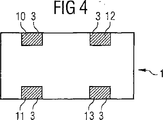
4 shows the plane of the element of FIG.
FIG. 5 shows a side view of the element of FIG.
FIG. 6 shows an equivalent circuit of the element of FIG.
FIG. 7 shows another possible embodiment of the resistor illustrated in FIG.
FIG. 8 shows another possible embodiment of the resistor illustrated in FIGS.
FIG. 9 schematically shows the attenuation characteristics of the element of FIG.
すべての図に対して、同じ参照符号は同じ要素を表していてもいることが言える。 For all figures, it can be said that the same reference numerals represent the same elements.
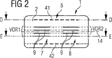
図2には本発明の多層素子が長手方向断面にて略示されている。それは基体1を有しており、基体には上下方向に積み重ねられた誘電体層2がスタックの形において含まれている。誘電体層2はセラミック材料を含んでいる。これらは図2では点線によって示されている。基体1には更に、上下方向に積み重ねられた電極層9のスタック7,8が含まれている。これらスタック7,8はそれぞれ、バリスタVDR1,VDR2を形成している。バリスタVDR1,VDR2の上方および下方にそれぞれ、抵抗41,42が配置されている。抵抗41,42はストラクチャ化された層5から形成されており、その形状は殊に図1から明らかである。図2には、ミアンダの個別の区間部分だけが横断面にて分かるように示されている。図2に図示の素子は平面14に対して対称的に実現されている。この平面は誘電体層2に対して平行に延在している。この対称性によって素子は、プリント基板における素子の配向が重要である高周波領域における使用に対して特別な利点を有している。素子の対称的な実現は、対称面に関する素子の位置ないし姿勢を考慮する必要がないことを意味している。
FIG. 2 schematically shows a multilayer element according to the invention in a longitudinal section. It has a substrate 1, which includes a dielectric layer 2 stacked in the vertical direction in the form of a stack. The dielectric layer 2 contains a ceramic material. These are indicated by dotted lines in FIG. The substrate 1 further includes
図1には、図2の素子の断面D−Dが示されている。 FIG. 1 shows a cross section DD of the element of FIG.
図1において抵抗41がどのような形状を有しているかが示されている。それはミアンダの形状を有してる。このミアンダは、幅bを有しているストリップによって形成される。図1に図示の例では、幅bは50μmである。図1に図示のミアンダの長さは約4000μmである。その際長さは、集まってミアンダを形成していると考えることができる個々の矩形の長さの加算によって決められる。従って抵抗に関して図1に示されている本発明の実施例は80という比L/Bを有している。これにより大きな抵抗が製造される。図1に図示の抵抗は約30Ωである。図1に図示のストリップはストラクチャ化された層5の形において被着されており、その際層厚は約2μmである。図1に図示の抵抗は、銀−パラジウム合金を含んでいる材料から形成されており、その際パラジウムは合金中30%の重量成分を有している。更に抵抗の出発材料はその他に有機物質および溶媒を含んでいる。これらの今述べた添加物は抵抗材料中に含まれていて、シルク印刷ペーストの形の抵抗がシルクスクリーン印刷法を用いてセラミック層上に被着できるようにする。これら成分は焼結の期間に焼成によって除去される。その際それは有機成分である。
FIG. 1 shows what shape the
図1には更に、抵抗41が素子の2つの外部コンタクト3を相互に接続していることが分かる。
FIG. 1 further shows that a
図1からは更に、図1に図示の平面には抵抗41の他に、コンデンサまたはバリスタに属している電極層が含まれていないことも分かる。従って、図1に図示の全体の面は抵抗を形成するミアンダを充填するために使用できるようになっている。
1 also shows that the plane shown in FIG. 1 does not include the electrode layer belonging to the capacitor or varistor in addition to the
図3には図2の素子をE−Eで切断して見た断面が示されている。図3には、左側に電極層9のスタック7の電極層9が見えかつ右側に電極層9のスタック8の電極層9が見えている。複数の同じ形式のこの種の電極層9は素子中で上下方向にスタックされている。これらは電極層9間に配置されているバリスタ材料に基づいてそれぞれバリスタVDR1,VDR2を形成するが、大面積のお互いに向き合っている電極層9に基づいて高い容量成分も有している。図1と図3をつき合わせてみると、特有の実施例による本発明の素子がフィードスルー素子として実現されていることが分かる。電極層9のそれぞれのスタック7,8に外部コンタクトの対10,11ないし12,13が配属されている。電極層9のスタック7,8内で、電極層9と外部コンタクト10,11ないし12,13とのコンタクト形成が交互に行われる。スタック7,8によって形成されるバリスタの回路技術的な結合は、図1ないし図2から明らかであるように、抵抗41ないし42によって行われる。
FIG. 3 shows a cross section of the element shown in FIG. In FIG. 3, the
図4および図5から、外部コンタクト3の位置が分かる。これらは基体1の2つの相対向している側面に配置されている。図4の平面が、外部コンタクト3は基板1の上側ないし相応に下側をも包囲していることが分かる。これにより、素子は上側または下側で表面実装技術によってプリント基板と導電接続することができる。
4 and 5, the position of the
図6には、図1ないし図3に示されている本発明の素子の等価回路が示されている。その際2つのバリスタVDR1,VDR2が回路技術的な抵抗Rによって相互に結合されてπフィルタを形成していることが明らかである。その際回路技術的な抵抗Rは、図2の2つの抵抗41,42の並列回路によって生じる。このことは、図2の抵抗42が図1の抵抗41と正確に同じように見えることから生じる。図6において素子の外部コンタクト3には詳細に参照番号が付されているので、素子の物理的な外部コンタクトの回路技術的な対応付けを行うことができる。
FIG. 6 shows an equivalent circuit of the element of the present invention shown in FIGS. In this case, it is clear that the two varistors VDR1 and VDR2 are connected to each other by a circuit technical resistor R to form a π filter. In this case, the circuit-technical resistance R is caused by the parallel circuit of the two
図7および図8は、図1に図示の抵抗41に代わって使用することができるような抵抗4に対する別の実施例が示されている。これによれば、図7は抵抗4に対する別のミアンダ構造を示している。その際抵抗4を形成する層5はミアンダの形においてストラクチャ化されている。ミアンダは、図1の幅bに相応していてよい幅bを持ったストリップによって形成される。図1との相異は、図7のミアンダは基板の長手方向ではなく、横断方向に延在している。
7 and 8 show another embodiment for a resistor 4 that can be used in place of the
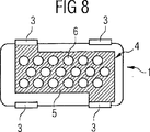
図8には、矩形の閉じられた層5から、層5中の切り欠き6の配置によって形成されている抵抗4が示されている。これら切り欠き6は円形であってよいが、これらは別の形状、例えば矩形を有していることもできる。多数の切り欠き6の均一な分配によって本来矩形の層5の抵抗を著しく高めることができる。切り欠き6の効果として、外部コンタクト3間で何回も湾曲している電流路が多数生じることであり、ここでの電流路は高い抵抗を有している。
FIG. 8 shows a resistor 4 formed from a rectangular
図9には、図2ないし6に示されている素子の挿入減衰が示されている。挿入減衰Sは周波数f〔MHz〕に関して単位dBで示されている。バリスタVDR1,VDR2に含まれている2つの容量C1,C2によって、共振周波数f1,f2が形成される。共振周波数f1,f2の個所で、素子は高められた減衰度を示している。共振周波数f1,f2の間にも素子はπ回路を実現している抵抗Rに基づいて非常に良好な減衰度を有している。これは740MHzおよび2.7GHz間の周波数間隔においてー20dBより良好である。これにより、素子は、共振周波数f1(C1に属している)と共振周波数f2(C2に属している)との間にある周波数バンドの障害防止に適している。共振周波数f1およびf2はバリスタVDR1およびVDR2の容量C1およびC2によって定められる。これらは周波数の換算によってC1=40pFおよびC2=20pFと突き止めることができる。抵抗Rは図示の実施例では1.8Ωである。 FIG. 9 shows the insertion attenuation of the elements shown in FIGS. The insertion attenuation S is shown in the unit dB with respect to the frequency f [MHz]. Resonant frequencies f 1 and f 2 are formed by the two capacitors C 1 and C 2 included in the varistors VDR 1 and VDR 2. At the resonance frequencies f 1 and f 2 , the element shows an increased attenuation. Even between the resonance frequencies f 1 and f 2, the element has a very good attenuation based on the resistance R realizing the π circuit. This is better than -20 dB in the frequency interval between 740 MHz and 2.7 GHz. Thus, the element is suitable for preventing a failure in a frequency band between the resonance frequency f1 (belonging to C1) and the resonance frequency f2 (belonging to C2). The resonance frequency f 1 and f 2 are determined by the capacitance C1 and C2 of the varistor VDR1 and Vdr2. These can be determined as C1 = 40 pF and C2 = 20 pF by frequency conversion. Resistor R is 1.8Ω in the illustrated embodiment.
Claims (14)
該基体(1)は2つの多層バリスタ(VDR1,VDR2)および抵抗(4)から形成されているπフィルタを有しており、
該基体(1)は、上下方向に重ねられているセラミックの誘電体層(2)のスタックを有し、
該基体(1)は、その表面に配置されている少なくとも4つの外部コンタクト(10,11,12,13)を有し、
基体(1)中に、それぞれ上下方向に重ねられていて、誘電体層(2)によって相互に分離されている電極層(9)の2つのスタック(7,8)が並んで配置されており、
第1のスタックの電極層(7)は、第1の外部コンタクト(10)および第2の外部コンタクト(11)に接続されており、
第2のスタックの電極層(8)は、第3の外部コンタクト(12)および第4の外部コンタクト(13)に接続されており、
なお、前記第1のスタック(7)および第2のスタック(8)は、それぞれ、前記多層バリスタ(VDR1,VDR2)の部分であり、
前記電極層(9)のスタック(7,8)の上側および下側に、前記抵抗(4)に対応する抵抗(41,42)がそれぞれ配置されており、かつ、
前記それぞれの抵抗(41,42)は、前記第1の外部コンタクト(10)よび第4の外部コンタクト(13)に並列に接続されており、
該基体(1)は、記誘電体層(2)に対して平行に延在している平面(14)に対して対称的に形成されている。 An electrical multilayer device comprising the following substrate (1).
The substrate (1) has a π filter formed of two multilayer varistors (VDR1, VDR2) and a resistor (4);
The substrate (1) has a stack of ceramic dielectric layers (2) stacked vertically,
The substrate (1) has at least four external contacts (10, 11, 12, 13) arranged on its surface;
In the substrate (1), two stacks (7, 8) of electrode layers (9), which are stacked one above the other and separated from each other by a dielectric layer (2), are arranged side by side. ,
The electrode layer (7) of the first stack is connected to the first external contact (10) and the second external contact (11),
The electrode layer (8) of the second stack is connected to the third external contact (12) and the fourth external contact (13),
The first stack (7) and the second stack (8) are parts of the multilayer varistors (VDR1, VDR2), respectively.
Resistors (41, 42) corresponding to the resistors (4) are respectively disposed above and below the stack (7, 8) of the electrode layer (9), and
The respective resistors (41, 42) are connected in parallel to the first external contact (10) and the fourth external contact (13),
The substrate (1) is formed symmetrically with respect to a plane (14) extending parallel to the dielectric layer (2).
抵抗(4,41,42)の平面には電極層(9)が存在していない、請求項1または2記載の素子。3. Element according to claim 1 or 2, wherein the electrode layer (9) is arranged on the substrate (1) and the electrode layer (9) is not present in the plane of the resistor (4, 41, 42).
Applications Claiming Priority (2)
| Application Number | Priority Date | Filing Date | Title |
|---|---|---|---|
| DE10144364A DE10144364A1 (en) | 2001-09-10 | 2001-09-10 | Electrical multilayer component |
| PCT/DE2002/002952 WO2003028045A2 (en) | 2001-09-10 | 2002-08-12 | Electrical multi-layer component |
Publications (2)
| Publication Number | Publication Date |
|---|---|
| JP2005504438A JP2005504438A (en) | 2005-02-10 |
| JP4095961B2 true JP4095961B2 (en) | 2008-06-04 |
Family
ID=7698380
Family Applications (1)
| Application Number | Title | Priority Date | Filing Date |
|---|---|---|---|
| JP2003531482A Expired - Fee Related JP4095961B2 (en) | 2001-09-10 | 2002-08-12 | Electrical multilayer element |
Country Status (8)
| Country | Link |
|---|---|
| US (1) | US7012501B2 (en) |
| EP (1) | EP1425762B1 (en) |
| JP (1) | JP4095961B2 (en) |
| CN (1) | CN100490025C (en) |
| AT (1) | ATE352847T1 (en) |
| DE (2) | DE10144364A1 (en) |
| TW (1) | TW569247B (en) |
| WO (1) | WO2003028045A2 (en) |
Families Citing this family (15)
| Publication number | Priority date | Publication date | Assignee | Title |
|---|---|---|---|---|
| DE10356498A1 (en) * | 2003-12-03 | 2005-07-07 | Epcos Ag | Electrical component and circuit arrangement |
| DE102004010001A1 (en) * | 2004-03-01 | 2005-09-22 | Epcos Ag | Electrical component comprises a stack of ceramic layers which form a base member, electrode layers, and a phase pushing unit |
| US7763833B2 (en) * | 2004-03-12 | 2010-07-27 | Goodrich Corp. | Foil heating element for an electrothermal deicer |
| DE102004037588A1 (en) * | 2004-08-03 | 2006-02-23 | Epcos Ag | Electrical component and method for producing an electrical component |
| JP4715248B2 (en) * | 2005-03-11 | 2011-07-06 | パナソニック株式会社 | Multilayer ceramic electronic components |
| US7923668B2 (en) * | 2006-02-24 | 2011-04-12 | Rohr, Inc. | Acoustic nacelle inlet lip having composite construction and an integral electric ice protection heater disposed therein |
| DE102006060634A1 (en) | 2006-12-21 | 2008-06-26 | Robert Bosch Gmbh | Method for producing an electrical resistance on a substrate |
| DE102007046607A1 (en) * | 2007-09-28 | 2009-04-02 | Epcos Ag | Electrical multilayer component and method for producing an electrical multilayer component |
| US8264816B2 (en) * | 2009-08-24 | 2012-09-11 | Kemet Electronics Corporation | Externally fused and resistively loaded safety capacitor |
| US8849404B2 (en) * | 2011-09-01 | 2014-09-30 | Medtronic, Inc. | Feedthrough assembly including a lead frame assembly |
| US9648743B2 (en) * | 2011-12-16 | 2017-05-09 | Snaptrack, Inc. | Multilayer glass ceramic substrate with embedded resistor |
| KR20150069901A (en) * | 2013-12-16 | 2015-06-24 | 삼성전기주식회사 | Resistor |
| AU2018205282A1 (en) * | 2017-01-06 | 2019-08-22 | Revolution Cooking, Llc | Heating element for a cooking appliance |
| CN107393784A (en) * | 2017-09-07 | 2017-11-24 | 上海长园维安电子线路保护有限公司 | It is a kind of can be resistant to high pressure from control type protector and preparation method thereof |
| JP7027176B2 (en) * | 2018-01-22 | 2022-03-01 | ラピスセミコンダクタ株式会社 | Semiconductor device |
Family Cites Families (28)
| Publication number | Priority date | Publication date | Assignee | Title |
|---|---|---|---|---|
| GB570026A (en) | 1943-12-14 | 1945-06-19 | Johnson Matthey Co Ltd | Improvements in or relating to the manufacture and production of electrical resistors with a low inductance |
| US3266005A (en) * | 1964-04-15 | 1966-08-09 | Western Electric Co | Apertured thin-film circuit components |
| US3846345A (en) * | 1969-10-06 | 1974-11-05 | Owens Illinois Inc | Electroconductive paste composition and structures formed therefrom |
| DE3125281A1 (en) | 1981-06-26 | 1983-01-13 | Siemens AG, 1000 Berlin und 8000 München | Electrical component combination, especially an R-C combination |
| DE3336229A1 (en) | 1983-10-05 | 1985-04-25 | Resista Fabrik elektrischer Widerstände GmbH, 8300 Landshut | METHOD FOR ADJUSTING THE VALUE OF RESISTORS |
| US4568908A (en) * | 1984-12-24 | 1986-02-04 | General Electric Company | Compact resistor assembly |
| EP0211331A3 (en) * | 1985-08-02 | 1989-10-25 | Hitachi, Ltd. | Heat-sensitive recording head and method of manufacturing same |
| US4811164A (en) | 1988-03-28 | 1989-03-07 | American Telephone And Telegraph Company, At&T Bell Laboratories | Monolithic capacitor-varistor |
| US4870746A (en) * | 1988-11-07 | 1989-10-03 | Litton Systems, Inc. | Method of making a multilayer printed circuit board having screened-on resistors |
| JPH02312203A (en) * | 1989-05-26 | 1990-12-27 | Matsushita Electric Ind Co Ltd | Method of trimming thick film resistor |
| DE69021689T2 (en) | 1989-10-26 | 1996-04-04 | Takeshi Ikeda | LC noise filter. |
| JPH0833327B2 (en) | 1990-06-11 | 1996-03-29 | 株式会社村田製作所 | Temperature sensor |
| JPH05275958A (en) * | 1992-03-25 | 1993-10-22 | Murata Mfg Co Ltd | Noise filter |
| JP3097332B2 (en) * | 1992-07-21 | 2000-10-10 | 株式会社村田製作所 | Stacked chip varistor |
| US5430429A (en) * | 1992-09-29 | 1995-07-04 | Murata Manufacturing Co., Ltd. | Ceramic resistor wherein a resistance film is embedded |
| US5379016A (en) * | 1993-06-03 | 1995-01-03 | E. I. Du Pont De Nemours And Company | Chip resistor |
| US5521576A (en) * | 1993-10-06 | 1996-05-28 | Collins; Franklyn M. | Fine-line thick film resistors and resistor networks and method of making same |
| JP3138631B2 (en) * | 1996-01-26 | 2001-02-26 | 太陽社電気株式会社 | Chip resistor and method of manufacturing the same |
| US5815367A (en) * | 1996-03-11 | 1998-09-29 | Murata Manufacturing Co., Ltd. | Layered capacitors having an internal inductor element |
| DE19612841A1 (en) | 1996-03-30 | 1997-10-02 | Abb Research Ltd | Current limiting resistor with PTC behavior |
| JP3631341B2 (en) * | 1996-10-18 | 2005-03-23 | Tdk株式会社 | Multilayer composite functional element and method for manufacturing the same |
| GB9623460D0 (en) * | 1996-11-09 | 1997-01-08 | Oxley Dev Co Ltd | Electronic components incorporating capacitors |
| JPH1116703A (en) * | 1997-06-20 | 1999-01-22 | Shoei Chem Ind Co | Ultra-small resistance resistor |
| US5889445A (en) * | 1997-07-22 | 1999-03-30 | Avx Corporation | Multilayer ceramic RC device |
| US6362723B1 (en) * | 1999-11-18 | 2002-03-26 | Murata Manufacturing Co., Ltd. | Chip thermistors |
| DE10108662A1 (en) * | 2000-02-23 | 2001-08-30 | Tyco Electronics Amp Gmbh | Conducting track on substrate has first and second straight sections connected by a third section running along an inwardly curved bend divided into mutually insulated sub-sections |
| DE10064447C2 (en) | 2000-12-22 | 2003-01-02 | Epcos Ag | Electrical multilayer component and interference suppression circuit with the component |
| EP1223591A3 (en) | 2001-01-11 | 2007-06-06 | Matsushita Electric Industrial Co., Ltd. | Multilayer electronic component and communication apparatus |
-
2001
- 2001-09-10 DE DE10144364A patent/DE10144364A1/en not_active Ceased
-
2002
- 2002-08-12 WO PCT/DE2002/002952 patent/WO2003028045A2/en active IP Right Grant
- 2002-08-12 EP EP02754524A patent/EP1425762B1/en not_active Expired - Lifetime
- 2002-08-12 CN CNB028176863A patent/CN100490025C/en not_active Expired - Fee Related
- 2002-08-12 DE DE50209370T patent/DE50209370D1/en not_active Expired - Lifetime
- 2002-08-12 US US10/488,518 patent/US7012501B2/en not_active Expired - Lifetime
- 2002-08-12 AT AT02754524T patent/ATE352847T1/en not_active IP Right Cessation
- 2002-08-12 JP JP2003531482A patent/JP4095961B2/en not_active Expired - Fee Related
- 2002-09-09 TW TW091120464A patent/TW569247B/en active
Also Published As
| Publication number | Publication date |
|---|---|
| US20040239476A1 (en) | 2004-12-02 |
| CN100490025C (en) | 2009-05-20 |
| EP1425762A2 (en) | 2004-06-09 |
| WO2003028045A3 (en) | 2003-12-04 |
| JP2005504438A (en) | 2005-02-10 |
| ATE352847T1 (en) | 2007-02-15 |
| EP1425762B1 (en) | 2007-01-24 |
| US7012501B2 (en) | 2006-03-14 |
| TW569247B (en) | 2004-01-01 |
| DE10144364A1 (en) | 2003-04-03 |
| WO2003028045A2 (en) | 2003-04-03 |
| CN1554101A (en) | 2004-12-08 |
| DE50209370D1 (en) | 2007-03-15 |
Similar Documents
| Publication | Publication Date | Title |
|---|---|---|
| JP4095961B2 (en) | Electrical multilayer element | |
| US4800459A (en) | Circuit substrate having ceramic multilayer structure containing chip-like electronic components | |
| JP5420619B2 (en) | Multilayer ceramic capacitor and manufacturing method thereof | |
| KR101856083B1 (en) | Multilayer ceramic capacitor | |
| JP2021010000A (en) | Multilayer ceramic capacitor and manufacturing method thereof | |
| US6525628B1 (en) | Surface mount RC array with narrow tab portions on each of the electrode plates | |
| JP2021002645A (en) | Multilayer ceramic capacitor and manufacturing method for the same | |
| KR102283078B1 (en) | Multi-layered ceramic capacitor and method of manufacturing the same | |
| JPH07326536A (en) | Ceramic capacitor | |
| KR102449359B1 (en) | Dielectric powder and multilayered ceramic electronic components using the same | |
| KR101882998B1 (en) | Laminated ceramic electronic parts | |
| KR102483618B1 (en) | Multi-layered ceramic capacitor and board for mounting the same | |
| KR102437803B1 (en) | Multi-layered ceramic electronic component | |
| JP2021103767A (en) | Multilayer ceramic capacitor and method of manufacturing the same | |
| KR20130012716A (en) | Multi-layered ceramic electronic parts | |
| JPH07272975A (en) | Composite capacitor | |
| JPH0897071A (en) | Multilayer ceramic capacitor | |
| US20150103468A1 (en) | Multilayer ceramic electronic component and method of manufacturing the same | |
| KR20050014094A (en) | Laminated chip element with various capacitance | |
| JPH0817675A (en) | Chip type laminated ceramic capacitor | |
| TWI440061B (en) | Electrical multi-layer-component | |
| US20170352490A1 (en) | Variable capacitance element | |
| KR102473419B1 (en) | Multi-layered ceramic electronic componentthe | |
| KR101973452B1 (en) | Multilayer ceramic capacitor | |
| US10204742B2 (en) | Variable capacitance element |
Legal Events
| Date | Code | Title | Description |
|---|---|---|---|
| A621 | Written request for application examination |
Free format text: JAPANESE INTERMEDIATE CODE: A621 Effective date: 20050714 |
|
| A977 | Report on retrieval |
Free format text: JAPANESE INTERMEDIATE CODE: A971007 Effective date: 20070521 |
|
| A131 | Notification of reasons for refusal |
Free format text: JAPANESE INTERMEDIATE CODE: A131 Effective date: 20070530 |
|
| A601 | Written request for extension of time |
Free format text: JAPANESE INTERMEDIATE CODE: A601 Effective date: 20070828 |
|
| A602 | Written permission of extension of time |
Free format text: JAPANESE INTERMEDIATE CODE: A602 Effective date: 20070904 |
|
| A601 | Written request for extension of time |
Free format text: JAPANESE INTERMEDIATE CODE: A601 Effective date: 20070928 |
|
| A602 | Written permission of extension of time |
Free format text: JAPANESE INTERMEDIATE CODE: A602 Effective date: 20071005 |
|
| A521 | Request for written amendment filed |
Free format text: JAPANESE INTERMEDIATE CODE: A523 Effective date: 20071129 |
|
| TRDD | Decision of grant or rejection written | ||
| A01 | Written decision to grant a patent or to grant a registration (utility model) |
Free format text: JAPANESE INTERMEDIATE CODE: A01 Effective date: 20080229 |
|
| A61 | First payment of annual fees (during grant procedure) |
Free format text: JAPANESE INTERMEDIATE CODE: A61 Effective date: 20080310 |
|
| FPAY | Renewal fee payment (event date is renewal date of database) |
Free format text: PAYMENT UNTIL: 20110314 Year of fee payment: 3 |
|
| R150 | Certificate of patent or registration of utility model |
Ref document number: 4095961 Country of ref document: JP Free format text: JAPANESE INTERMEDIATE CODE: R150 Free format text: JAPANESE INTERMEDIATE CODE: R150 |
|
| FPAY | Renewal fee payment (event date is renewal date of database) |
Free format text: PAYMENT UNTIL: 20110314 Year of fee payment: 3 |
|
| R250 | Receipt of annual fees |
Free format text: JAPANESE INTERMEDIATE CODE: R250 |
|
| FPAY | Renewal fee payment (event date is renewal date of database) |
Free format text: PAYMENT UNTIL: 20120314 Year of fee payment: 4 |
|
| FPAY | Renewal fee payment (event date is renewal date of database) |
Free format text: PAYMENT UNTIL: 20130314 Year of fee payment: 5 |
|
| R250 | Receipt of annual fees |
Free format text: JAPANESE INTERMEDIATE CODE: R250 |
|
| FPAY | Renewal fee payment (event date is renewal date of database) |
Free format text: PAYMENT UNTIL: 20130314 Year of fee payment: 5 |
|
| FPAY | Renewal fee payment (event date is renewal date of database) |
Free format text: PAYMENT UNTIL: 20140314 Year of fee payment: 6 |
|
| R250 | Receipt of annual fees |
Free format text: JAPANESE INTERMEDIATE CODE: R250 |
|
| R250 | Receipt of annual fees |
Free format text: JAPANESE INTERMEDIATE CODE: R250 |
|
| R250 | Receipt of annual fees |
Free format text: JAPANESE INTERMEDIATE CODE: R250 |
|
| R250 | Receipt of annual fees |
Free format text: JAPANESE INTERMEDIATE CODE: R250 |
|
| R250 | Receipt of annual fees |
Free format text: JAPANESE INTERMEDIATE CODE: R250 |
|
| R250 | Receipt of annual fees |
Free format text: JAPANESE INTERMEDIATE CODE: R250 |
|
| R250 | Receipt of annual fees |
Free format text: JAPANESE INTERMEDIATE CODE: R250 |
|
| R250 | Receipt of annual fees |
Free format text: JAPANESE INTERMEDIATE CODE: R250 |
|
| LAPS | Cancellation because of no payment of annual fees |