JP4095368B2 - Method for producing ink jet recording head - Google Patents
Method for producing ink jet recording head Download PDFInfo
- Publication number
- JP4095368B2 JP4095368B2 JP2002216166A JP2002216166A JP4095368B2 JP 4095368 B2 JP4095368 B2 JP 4095368B2 JP 2002216166 A JP2002216166 A JP 2002216166A JP 2002216166 A JP2002216166 A JP 2002216166A JP 4095368 B2 JP4095368 B2 JP 4095368B2
- Authority
- JP
- Japan
- Prior art keywords
- recording head
- movable member
- ink
- jet recording
- ink jet
- Prior art date
- Legal status (The legal status is an assumption and is not a legal conclusion. Google has not performed a legal analysis and makes no representation as to the accuracy of the status listed.)
- Expired - Fee Related
Links
- 238000004519 manufacturing process Methods 0.000 title claims abstract description 56
- 239000011347 resin Substances 0.000 claims abstract description 88
- 229920005989 resin Polymers 0.000 claims abstract description 88
- 238000000034 method Methods 0.000 claims abstract description 83
- 239000000758 substrate Substances 0.000 claims abstract description 53
- 238000010438 heat treatment Methods 0.000 claims abstract description 17
- 239000000463 material Substances 0.000 claims description 28
- 230000004888 barrier function Effects 0.000 claims description 14
- 229920002120 photoresistant polymer Polymers 0.000 claims description 7
- 238000007599 discharging Methods 0.000 claims description 5
- 230000004044 response Effects 0.000 abstract description 3
- 230000005587 bubbling Effects 0.000 abstract 1
- 230000008569 process Effects 0.000 description 64
- 239000010410 layer Substances 0.000 description 58
- 239000007788 liquid Substances 0.000 description 13
- JHIVVAPYMSGYDF-UHFFFAOYSA-N cyclohexanone Chemical compound O=C1CCCCC1 JHIVVAPYMSGYDF-UHFFFAOYSA-N 0.000 description 8
- 238000000059 patterning Methods 0.000 description 8
- 239000004593 Epoxy Substances 0.000 description 6
- HEMHJVSKTPXQMS-UHFFFAOYSA-M Sodium hydroxide Chemical compound [OH-].[Na+] HEMHJVSKTPXQMS-UHFFFAOYSA-M 0.000 description 6
- 238000004132 cross linking Methods 0.000 description 6
- 238000006073 displacement reaction Methods 0.000 description 6
- 239000000243 solution Substances 0.000 description 6
- 239000002904 solvent Substances 0.000 description 5
- KWYUFKZDYYNOTN-UHFFFAOYSA-M Potassium hydroxide Chemical compound [OH-].[K+] KWYUFKZDYYNOTN-UHFFFAOYSA-M 0.000 description 4
- 238000003486 chemical etching Methods 0.000 description 4
- 238000006243 chemical reaction Methods 0.000 description 4
- 239000011248 coating agent Substances 0.000 description 4
- 238000000576 coating method Methods 0.000 description 4
- IWVKTOUOPHGZRX-UHFFFAOYSA-N methyl 2-methylprop-2-enoate;2-methylprop-2-enoic acid Chemical compound CC(=C)C(O)=O.COC(=O)C(C)=C IWVKTOUOPHGZRX-UHFFFAOYSA-N 0.000 description 4
- 239000011241 protective layer Substances 0.000 description 4
- 238000004528 spin coating Methods 0.000 description 4
- WGTYBPLFGIVFAS-UHFFFAOYSA-M tetramethylammonium hydroxide Chemical compound [OH-].C[N+](C)(C)C WGTYBPLFGIVFAS-UHFFFAOYSA-M 0.000 description 4
- 238000005530 etching Methods 0.000 description 3
- 230000001678 irradiating effect Effects 0.000 description 3
- 230000004048 modification Effects 0.000 description 3
- 238000012986 modification Methods 0.000 description 3
- 238000000206 photolithography Methods 0.000 description 3
- 230000035945 sensitivity Effects 0.000 description 3
- CERQOIWHTDAKMF-UHFFFAOYSA-N Methacrylic acid Chemical compound CC(=C)C(O)=O CERQOIWHTDAKMF-UHFFFAOYSA-N 0.000 description 2
- 230000009471 action Effects 0.000 description 2
- 239000012670 alkaline solution Substances 0.000 description 2
- 238000006482 condensation reaction Methods 0.000 description 2
- 229920001577 copolymer Polymers 0.000 description 2
- 230000018044 dehydration Effects 0.000 description 2
- 238000006297 dehydration reaction Methods 0.000 description 2
- 238000010586 diagram Methods 0.000 description 2
- 238000001312 dry etching Methods 0.000 description 2
- 230000000694 effects Effects 0.000 description 2
- 230000005611 electricity Effects 0.000 description 2
- 238000010894 electron beam technology Methods 0.000 description 2
- 238000005187 foaming Methods 0.000 description 2
- 238000003860 storage Methods 0.000 description 2
- WQMWHMMJVJNCAL-UHFFFAOYSA-N 2,4-dimethylpenta-1,4-dien-3-one Chemical compound CC(=C)C(=O)C(C)=C WQMWHMMJVJNCAL-UHFFFAOYSA-N 0.000 description 1
- VVQNEPGJFQJSBK-UHFFFAOYSA-N Methyl methacrylate Chemical compound COC(=O)C(C)=C VVQNEPGJFQJSBK-UHFFFAOYSA-N 0.000 description 1
- XUIMIQQOPSSXEZ-UHFFFAOYSA-N Silicon Chemical compound [Si] XUIMIQQOPSSXEZ-UHFFFAOYSA-N 0.000 description 1
- 230000006378 damage Effects 0.000 description 1
- 238000000354 decomposition reaction Methods 0.000 description 1
- 230000007423 decrease Effects 0.000 description 1
- 230000020169 heat generation Effects 0.000 description 1
- 238000005338 heat storage Methods 0.000 description 1
- 230000006872 improvement Effects 0.000 description 1
- 239000004973 liquid crystal related substance Substances 0.000 description 1
- 230000007774 longterm Effects 0.000 description 1
- 238000002844 melting Methods 0.000 description 1
- 230000008018 melting Effects 0.000 description 1
- 239000000203 mixture Substances 0.000 description 1
- 238000010526 radical polymerization reaction Methods 0.000 description 1
- 230000009467 reduction Effects 0.000 description 1
- 229910052710 silicon Inorganic materials 0.000 description 1
- 239000010703 silicon Substances 0.000 description 1
- 230000008961 swelling Effects 0.000 description 1
- 230000004304 visual acuity Effects 0.000 description 1
Images


Classifications
-
- B—PERFORMING OPERATIONS; TRANSPORTING
- B41—PRINTING; LINING MACHINES; TYPEWRITERS; STAMPS
- B41J—TYPEWRITERS; SELECTIVE PRINTING MECHANISMS, i.e. MECHANISMS PRINTING OTHERWISE THAN FROM A FORME; CORRECTION OF TYPOGRAPHICAL ERRORS
- B41J2/00—Typewriters or selective printing mechanisms characterised by the printing or marking process for which they are designed
- B41J2/005—Typewriters or selective printing mechanisms characterised by the printing or marking process for which they are designed characterised by bringing liquid or particles selectively into contact with a printing material
- B41J2/01—Ink jet
- B41J2/135—Nozzles
- B41J2/16—Production of nozzles
- B41J2/1621—Manufacturing processes
- B41J2/164—Manufacturing processes thin film formation
- B41J2/1645—Manufacturing processes thin film formation thin film formation by spincoating
-
- B—PERFORMING OPERATIONS; TRANSPORTING
- B41—PRINTING; LINING MACHINES; TYPEWRITERS; STAMPS
- B41J—TYPEWRITERS; SELECTIVE PRINTING MECHANISMS, i.e. MECHANISMS PRINTING OTHERWISE THAN FROM A FORME; CORRECTION OF TYPOGRAPHICAL ERRORS
- B41J2/00—Typewriters or selective printing mechanisms characterised by the printing or marking process for which they are designed
- B41J2/315—Typewriters or selective printing mechanisms characterised by the printing or marking process for which they are designed characterised by selective application of heat to a heat sensitive printing or impression-transfer material
- B41J2/32—Typewriters or selective printing mechanisms characterised by the printing or marking process for which they are designed characterised by selective application of heat to a heat sensitive printing or impression-transfer material using thermal heads
- B41J2/335—Structure of thermal heads
-
- B—PERFORMING OPERATIONS; TRANSPORTING
- B41—PRINTING; LINING MACHINES; TYPEWRITERS; STAMPS
- B41J—TYPEWRITERS; SELECTIVE PRINTING MECHANISMS, i.e. MECHANISMS PRINTING OTHERWISE THAN FROM A FORME; CORRECTION OF TYPOGRAPHICAL ERRORS
- B41J2/00—Typewriters or selective printing mechanisms characterised by the printing or marking process for which they are designed
- B41J2/005—Typewriters or selective printing mechanisms characterised by the printing or marking process for which they are designed characterised by bringing liquid or particles selectively into contact with a printing material
- B41J2/01—Ink jet
- B41J2/135—Nozzles
- B41J2/14—Structure thereof only for on-demand ink jet heads
- B41J2/14016—Structure of bubble jet print heads
- B41J2/14032—Structure of the pressure chamber
- B41J2/1404—Geometrical characteristics
-
- B—PERFORMING OPERATIONS; TRANSPORTING
- B41—PRINTING; LINING MACHINES; TYPEWRITERS; STAMPS
- B41J—TYPEWRITERS; SELECTIVE PRINTING MECHANISMS, i.e. MECHANISMS PRINTING OTHERWISE THAN FROM A FORME; CORRECTION OF TYPOGRAPHICAL ERRORS
- B41J2/00—Typewriters or selective printing mechanisms characterised by the printing or marking process for which they are designed
- B41J2/005—Typewriters or selective printing mechanisms characterised by the printing or marking process for which they are designed characterised by bringing liquid or particles selectively into contact with a printing material
- B41J2/01—Ink jet
- B41J2/135—Nozzles
- B41J2/14—Structure thereof only for on-demand ink jet heads
- B41J2/14016—Structure of bubble jet print heads
- B41J2/14032—Structure of the pressure chamber
- B41J2/14048—Movable member in the chamber
-
- B—PERFORMING OPERATIONS; TRANSPORTING
- B41—PRINTING; LINING MACHINES; TYPEWRITERS; STAMPS
- B41J—TYPEWRITERS; SELECTIVE PRINTING MECHANISMS, i.e. MECHANISMS PRINTING OTHERWISE THAN FROM A FORME; CORRECTION OF TYPOGRAPHICAL ERRORS
- B41J2/00—Typewriters or selective printing mechanisms characterised by the printing or marking process for which they are designed
- B41J2/005—Typewriters or selective printing mechanisms characterised by the printing or marking process for which they are designed characterised by bringing liquid or particles selectively into contact with a printing material
- B41J2/01—Ink jet
- B41J2/135—Nozzles
- B41J2/16—Production of nozzles
- B41J2/1601—Production of bubble jet print heads
- B41J2/1603—Production of bubble jet print heads of the front shooter type
-
- B—PERFORMING OPERATIONS; TRANSPORTING
- B41—PRINTING; LINING MACHINES; TYPEWRITERS; STAMPS
- B41J—TYPEWRITERS; SELECTIVE PRINTING MECHANISMS, i.e. MECHANISMS PRINTING OTHERWISE THAN FROM A FORME; CORRECTION OF TYPOGRAPHICAL ERRORS
- B41J2/00—Typewriters or selective printing mechanisms characterised by the printing or marking process for which they are designed
- B41J2/005—Typewriters or selective printing mechanisms characterised by the printing or marking process for which they are designed characterised by bringing liquid or particles selectively into contact with a printing material
- B41J2/01—Ink jet
- B41J2/135—Nozzles
- B41J2/16—Production of nozzles
- B41J2/1621—Manufacturing processes
- B41J2/1626—Manufacturing processes etching
- B41J2/1628—Manufacturing processes etching dry etching
-
- B—PERFORMING OPERATIONS; TRANSPORTING
- B41—PRINTING; LINING MACHINES; TYPEWRITERS; STAMPS
- B41J—TYPEWRITERS; SELECTIVE PRINTING MECHANISMS, i.e. MECHANISMS PRINTING OTHERWISE THAN FROM A FORME; CORRECTION OF TYPOGRAPHICAL ERRORS
- B41J2/00—Typewriters or selective printing mechanisms characterised by the printing or marking process for which they are designed
- B41J2/005—Typewriters or selective printing mechanisms characterised by the printing or marking process for which they are designed characterised by bringing liquid or particles selectively into contact with a printing material
- B41J2/01—Ink jet
- B41J2/135—Nozzles
- B41J2/16—Production of nozzles
- B41J2/1621—Manufacturing processes
- B41J2/1626—Manufacturing processes etching
- B41J2/1629—Manufacturing processes etching wet etching
-
- B—PERFORMING OPERATIONS; TRANSPORTING
- B41—PRINTING; LINING MACHINES; TYPEWRITERS; STAMPS
- B41J—TYPEWRITERS; SELECTIVE PRINTING MECHANISMS, i.e. MECHANISMS PRINTING OTHERWISE THAN FROM A FORME; CORRECTION OF TYPOGRAPHICAL ERRORS
- B41J2/00—Typewriters or selective printing mechanisms characterised by the printing or marking process for which they are designed
- B41J2/005—Typewriters or selective printing mechanisms characterised by the printing or marking process for which they are designed characterised by bringing liquid or particles selectively into contact with a printing material
- B41J2/01—Ink jet
- B41J2/135—Nozzles
- B41J2/16—Production of nozzles
- B41J2/1621—Manufacturing processes
- B41J2/1631—Manufacturing processes photolithography
-
- B—PERFORMING OPERATIONS; TRANSPORTING
- B41—PRINTING; LINING MACHINES; TYPEWRITERS; STAMPS
- B41J—TYPEWRITERS; SELECTIVE PRINTING MECHANISMS, i.e. MECHANISMS PRINTING OTHERWISE THAN FROM A FORME; CORRECTION OF TYPOGRAPHICAL ERRORS
- B41J2/00—Typewriters or selective printing mechanisms characterised by the printing or marking process for which they are designed
- B41J2/005—Typewriters or selective printing mechanisms characterised by the printing or marking process for which they are designed characterised by bringing liquid or particles selectively into contact with a printing material
- B41J2/01—Ink jet
- B41J2/135—Nozzles
- B41J2/16—Production of nozzles
- B41J2/1621—Manufacturing processes
- B41J2/1637—Manufacturing processes molding
- B41J2/1639—Manufacturing processes molding sacrificial molding
-
- B—PERFORMING OPERATIONS; TRANSPORTING
- B41—PRINTING; LINING MACHINES; TYPEWRITERS; STAMPS
- B41J—TYPEWRITERS; SELECTIVE PRINTING MECHANISMS, i.e. MECHANISMS PRINTING OTHERWISE THAN FROM A FORME; CORRECTION OF TYPOGRAPHICAL ERRORS
- B41J2/00—Typewriters or selective printing mechanisms characterised by the printing or marking process for which they are designed
- B41J2/005—Typewriters or selective printing mechanisms characterised by the printing or marking process for which they are designed characterised by bringing liquid or particles selectively into contact with a printing material
- B41J2/01—Ink jet
- B41J2/135—Nozzles
- B41J2/14—Structure thereof only for on-demand ink jet heads
- B41J2002/14387—Front shooter
-
- Y—GENERAL TAGGING OF NEW TECHNOLOGICAL DEVELOPMENTS; GENERAL TAGGING OF CROSS-SECTIONAL TECHNOLOGIES SPANNING OVER SEVERAL SECTIONS OF THE IPC; TECHNICAL SUBJECTS COVERED BY FORMER USPC CROSS-REFERENCE ART COLLECTIONS [XRACs] AND DIGESTS
- Y10—TECHNICAL SUBJECTS COVERED BY FORMER USPC
- Y10T—TECHNICAL SUBJECTS COVERED BY FORMER US CLASSIFICATION
- Y10T29/00—Metal working
- Y10T29/49—Method of mechanical manufacture
- Y10T29/49002—Electrical device making
- Y10T29/49082—Resistor making
- Y10T29/49083—Heater type
-
- Y—GENERAL TAGGING OF NEW TECHNOLOGICAL DEVELOPMENTS; GENERAL TAGGING OF CROSS-SECTIONAL TECHNOLOGIES SPANNING OVER SEVERAL SECTIONS OF THE IPC; TECHNICAL SUBJECTS COVERED BY FORMER USPC CROSS-REFERENCE ART COLLECTIONS [XRACs] AND DIGESTS
- Y10—TECHNICAL SUBJECTS COVERED BY FORMER USPC
- Y10T—TECHNICAL SUBJECTS COVERED BY FORMER US CLASSIFICATION
- Y10T29/00—Metal working
- Y10T29/49—Method of mechanical manufacture
- Y10T29/49002—Electrical device making
- Y10T29/49117—Conductor or circuit manufacturing
- Y10T29/49124—On flat or curved insulated base, e.g., printed circuit, etc.
- Y10T29/4913—Assembling to base an electrical component, e.g., capacitor, etc.
-
- Y—GENERAL TAGGING OF NEW TECHNOLOGICAL DEVELOPMENTS; GENERAL TAGGING OF CROSS-SECTIONAL TECHNOLOGIES SPANNING OVER SEVERAL SECTIONS OF THE IPC; TECHNICAL SUBJECTS COVERED BY FORMER USPC CROSS-REFERENCE ART COLLECTIONS [XRACs] AND DIGESTS
- Y10—TECHNICAL SUBJECTS COVERED BY FORMER USPC
- Y10T—TECHNICAL SUBJECTS COVERED BY FORMER US CLASSIFICATION
- Y10T29/00—Metal working
- Y10T29/49—Method of mechanical manufacture
- Y10T29/49002—Electrical device making
- Y10T29/49117—Conductor or circuit manufacturing
- Y10T29/49124—On flat or curved insulated base, e.g., printed circuit, etc.
- Y10T29/49155—Manufacturing circuit on or in base
- Y10T29/49158—Manufacturing circuit on or in base with molding of insulated base
-
- Y—GENERAL TAGGING OF NEW TECHNOLOGICAL DEVELOPMENTS; GENERAL TAGGING OF CROSS-SECTIONAL TECHNOLOGIES SPANNING OVER SEVERAL SECTIONS OF THE IPC; TECHNICAL SUBJECTS COVERED BY FORMER USPC CROSS-REFERENCE ART COLLECTIONS [XRACs] AND DIGESTS
- Y10—TECHNICAL SUBJECTS COVERED BY FORMER USPC
- Y10T—TECHNICAL SUBJECTS COVERED BY FORMER US CLASSIFICATION
- Y10T29/00—Metal working
- Y10T29/49—Method of mechanical manufacture
- Y10T29/49002—Electrical device making
- Y10T29/49117—Conductor or circuit manufacturing
- Y10T29/49169—Assembling electrical component directly to terminal or elongated conductor
- Y10T29/49171—Assembling electrical component directly to terminal or elongated conductor with encapsulating
- Y10T29/49172—Assembling electrical component directly to terminal or elongated conductor with encapsulating by molding of insulating material
-
- Y—GENERAL TAGGING OF NEW TECHNOLOGICAL DEVELOPMENTS; GENERAL TAGGING OF CROSS-SECTIONAL TECHNOLOGIES SPANNING OVER SEVERAL SECTIONS OF THE IPC; TECHNICAL SUBJECTS COVERED BY FORMER USPC CROSS-REFERENCE ART COLLECTIONS [XRACs] AND DIGESTS
- Y10—TECHNICAL SUBJECTS COVERED BY FORMER USPC
- Y10T—TECHNICAL SUBJECTS COVERED BY FORMER US CLASSIFICATION
- Y10T29/00—Metal working
- Y10T29/49—Method of mechanical manufacture
- Y10T29/49401—Fluid pattern dispersing device making, e.g., ink jet
Landscapes
- Engineering & Computer Science (AREA)
- Manufacturing & Machinery (AREA)
- Physics & Mathematics (AREA)
- Geometry (AREA)
- Particle Formation And Scattering Control In Inkjet Printers (AREA)
Abstract
Description
【0001】
【発明の属する技術分野】
本発明は、液体をオリフィス(吐出口)から噴射して液滴を形成するインクジェット記録ヘッドの作成方法に関する。
【0002】
【従来の技術】
液体をオリフィスから噴射して液滴を形成するこの種のインクジェット記録ヘッドに関し、例えば特開昭54−51837号公報に記載されているインクジェット記録法は、熱エネルギーを液体に作用させて、液滴吐出の原動力を得るという点において、他のインクジェット記録方法とは異なる特徴を有している。
【0003】
即ち、上述の公報に開示されている記録法は、熱エネルギーの作用を受けた液体が過熱されて気泡を発生し、この気泡発生に基づく作用力によって、記録ヘッド部先端のオリフィスから液滴が形成され、この液滴が被記録部材に付着して情報の記録が行われるということを特徴としている。
【0004】
この記録法に適用される記録ヘッドは、一般に液体を吐出するために設けられたオリフィスと、このオリフィスに連通して液滴を吐出するための熱エネルギーが液体に作用する部分である熱作用部を構成の一部とする液流路とを有する液吐出部及び熱エネルギーを発生する手段である熱変換体としての発熱抵抗層とそれをインクから保護する上部保護層と蓄熱するための下部層を具備している。
【0005】
【発明が解決しようとする課題】
上記のような熱エネルギーを液体に作用させて、液滴吐出の原動力を得るインクジェット記録ヘッドにおいて、その印字スピードの向上のため、インクジェット記録ヘッドに求められる性能として周波数特性の向上がある。この周波数特性を向上するためには、液滴を吐出した後のインクのリフィル性能を上げる必要がある。インクのリフィル性能を上げるためにはインク供給口から吐出口までの流抵抗を低減することが必要となる。
【0006】
しかしながら、流抵抗の低減をすると発泡圧力がインク供給口側へ逃げてしまい、吐出速度の低下及び安定性が無くなり吐出性能が悪くなり印字が悪くなることとなる。このため、吐出性能を維持し周波数特性を向上することは非常に困難であった。
【0007】
更には、近年の高画質に対する市場の要望に答えるために、高解像度、且つ、小液滴による印字物を達成するために、インクジェットプリントヘッドは、高密度に配列され、且つ、吐出口からは、微小な液滴を飛翔させる必要がある。
【0008】
一方、インク供給口と吐出口の間におけるノズル流路内にいわゆる流体ダイオードとなる可動部材を設けることにより、吐出性能を維持しつつ周波数特性を向上させることが提案されている。しかし、そのような従来のインクジェット記録ヘッドでは、可動部材が剥がれたり破壊されたりしてしまう場合があった。
【0009】
そこで、本発明は、上記課題を解決し、インク供給口と吐出口の間におけるノズル流路に可動部材を形成し、吐出性能を維持し周波数特性を向上することを可能とした高密度、高精度、高信頼性のインクジェット記録ヘッドの作成方法を提供することを目的とする。
【0010】
【課題を解決するための手段】
本発明は、上記課題を解決するために、つぎの(1)〜(4)のように構成したインクジェット記録ヘッドの作成方法を提供するものである。
(1)発熱抵抗体と、該発熱抵抗体に対応して設けられたインク吐出口と、該インク吐出口に連通するノズル流路と、を有し、該ノズル流路内の、前記発熱抵抗体と、前記ノズル流路内にインクを供給するためのインク供給口と、の間に可動部材が形成されており、前記発熱抵抗体の発熱によりノズル流路内のインク中に発生させた気泡を利用して前記インク吐出口からインクを吐出するインクジェット記録ヘッドの作成方法において、
前記発熱抵抗体を備えた基板を準備する工程と、
該基板上に、前記ノズル流路及び前記可動部材を形成するための第1の型材となる第1の樹脂を塗布する工程と、
該第1の樹脂により前記第1の型材を形成する工程と、
前記第1の型材を覆うように、前記基板上に前記ノズル流路及び前記可動部材を形成するための第2の樹脂を塗布する工程と、
前記第1の型材を除去する工程と、を有することを特徴とするインクジェット記録ヘッドの作成方法。
(2)前記第1の樹脂はフォトレジストであって、前記第1の型材を形成する工程では、前記フォトレジストの解像度限界以下の幅を有するマスクパターンを用いて前記第1の型材の、前記可動部材を形成するための部分を形成する工程を含むことを特徴とする上記(1)に記載のインクジェット記録ヘッドの作成方法。
(3)前記第1の樹脂を塗布する工程の前に、前記基板上に、前記ノズル流路を形成するための第2の型材となる第3の樹脂を塗布する工程を、さらに有し、
前記第1の樹脂を塗布する工程は、前記第2の型材を前記第1の樹脂で覆うように前記基板上に前記第1の樹脂を塗布する工程であることを特徴とする
上記(1)に記載のインクジェット記録ヘッドの作成方法。
(4)前記基板上に、前記第1の樹脂を塗布する前に、前記基板上の、前記可動部材と前記供給口との間に対応する位置に前記可動部材が前記供給口側に変位することを制限するための突状障壁を形成する工程をさらに有することを特徴とする上記(1)に記載のインクジェット記録ヘッドの作成方法。
【0011】
【発明の実施の形態】
上記構成を適用したインクジェット記録ヘッドの作成方法によれば、可動部材がノズル型材のパターニング時に型を形成できるので、可動部材とノズル流路がフォトリソグラフィ法で高密度、高精度に形成することができ、高密度、高精度のインクジェット記録ヘッドの作成が可能となる。
さらに、可動部材を形成する方法として、前記第1の樹脂の解像度限界以下の幅を有するマスクパターンを用いて前記第1の型材の、前記可動部材を形成するための部分を形成し、その部分に後に塗布する樹脂によって可動部材を形成すれば、ノズル流路と可動部材の形成部分の型材を同一のマスクで形成することが可能となる。したがって、ノズル流路と可動部材がマスク作成精度で形成することができる。また、パターニング工程を一つ省略することが出来、コストの低減化を図ることができる。
また、上記構成を適用したインクジェット記録ヘッドによれば、インク流路を構成する材料と同じ材料によって可動部材を形成することができ、可動部材とインク流路が一体に形成されることから、可動部材を別部品として付ける方法と比較して、可動部材の剥がれや破壊が生じ難く、信頼性が高いインクジェットヘッドを提供することができる。
【0012】
【実施例】
以下に、本発明の実施例について説明する。なお、図22は本発明実施例におけるインクジェット記録ヘッドの模式的な斜視図を示している。発熱抵抗体3及びインク供給口5を備えた基板1上にインク流路を構成する部材12及び吐出口7が形成されている。なお、以下で本発明の各実施例におけるインクジェット記録ヘッドの作成方法を説明するための、図1〜5(実施例1),図6〜9(実施例2),図12〜14(実施例3)及び図15〜17(実施例4)に示す断面図は、図22のA−A’線における断面図に相当する。
【0013】
[実施例1]
本発明の実施例1におけるインクジェット記録ヘッドの作成方法を、図1〜図5を用いて説明する。
まず、シリコン基板上101に蓄熱層102を形成し、25μm角のヒータ(発熱抵抗体)103を600dpiに配列し、その上に保護層104を形成する(図1(a)及び図1(b))。
次に、第一の型レジスト108を3μm塗布する(図1(c)及び図1(d))。
次に、第一の型レジスト108をノズル流路の形状に露光、現像によりパターニングする(図2(a)及び図2(b))。
【0014】
次に、前記パターニングされた上に、第二の型レジスト109を12μm塗布する(図2(c)及び図2(d))。
次に、第二の型レジスト109をノズル流路形状と可動部材形状111(5μm×25μm)に露光、現像によりパターニングする(図3(a)及び図3(b))。
次に、ノズル流路、吐出口、可動部材を形成するための感光性エポキシ材112を塗布する(図3(c)及び図3(d))。
【0015】
次に、吐出口107を露光、現像によって直径18μmの形状にパターニングによって形成する(図4(a)及び図4(b))。
次に、基板裏面からドライエッチング法によってインク供給口105を形成する(図4(c)及び図4(d))。
【0016】
最後に、型材となったレジストを、剥離液を用いて除去し、可動部材110の形成されたノズル106付きのヘッドチップが完成する(図5(a)及び図5(b))。このようにしてノズル流路内に形成された可動部材は、発熱抵抗体が設けられた側の基板面に対向するノズル流路の壁面に支点を有するとともに、該基板面側に自由端を有する。
そして、インク供給するためのチューブとヒータを発熱するための電気を供給するための電気実装をしてインクジェット記録ヘッドが完成する。
【0017】
このようにして完成されたヘッドは周波数応答性が高く、吐出性能が良い。したがって、高速に良好な印字が可能になった。
また、可動部材を形成するためのパターニングがフォトリソグラフィ法であることから、可動部材を高精度で形成できるうえ、ヒータ、ノズル、及び吐出口に対して高精度で可動部材を配置することが出来る。したがって、今後の小液滴化、高密度化に十分対応が可能である。
【0018】
さらに、ノズル、吐出口を形成するエポキシ材と一体で形成できることから、長期使用時の剥がれ破壊などが生じ難く、また耐インク性があるエポキシ材を選定することによってエポキシ材からの溶質及び膨れなど発生しない。
したがって、信頼性の高いヘッドを提供することができる。
【0019】
[実施例2]
本発明の実施例2におけるインクジェット記録ヘッドの作成方法を、図6〜図9を用いて説明する。
まず、実施例1と同様にして25μm角のヒータを600dpiに配列したヒータ203付き基板201を作成する(図6(a)及び図6(b))。
【0020】
次に、型材となるフォトレジスト208を20μm塗布する(図6(c)及び図6(d))。
次に、図10に示すようなノズル流路形状と可動部材形状(2μm×25μm)のマスクパターンを有するマスクを用いて露光、現像しパターンを形成する。
本実施例で用いているフォトレジスト208は、厚さ20μmにおいて解像度は4μmであるので、マスクパターンの可動部材の厚さに対応する部分の幅Wを解像度限界以下の2μmとしたマスクを用いてパターニングした。
【0021】
このように解像度限界以下のマスクで形成すると図7(a)及び図7(b)に示すようにレジストの途中までパターニングされる。したがって、基板までパターンが到達しないので、可動が可能な可動部材の型材として機能することができる。
次に、ノズル流路206、吐出口207、可動部材210を形成するための感光性エポキシを塗布する(図7(c)及び図7(d))。
次に、吐出口を露光、現像によって直径18μmの形状にパターニングによって形成する(図8(a)及び図8(b))。
【0022】
次に、基板裏面からドライエッチ法によってインク供給口205を形成する(図8(c)及び図8(d))。
最後に、型材となったレジストを、剥離液を用いて除去し、ノズル付きの基板が完成する(図9(a)及び図9(b))。
そして、インク供給するためのチューブ(不図示)を接続しヒータ203を発熱するための電気を供給するための電気配線基板(不図示)を接続してインクジェット記録ヘッドが完成する。
このようにして完成されたヘッドは周波数応答性が高く、吐出性能が良い。したがって、高速に良好な印字が可能になった。
【0023】
実施例1の効果に加えさらに型レジストの塗布、露光、現像の工程を一つ省略できることによって、コストを削減することが可能になった。
また、ノズル流路206と可動部材210を同一のマスクで作成することができるので、アライメント精度をさらに向上させることが可能となる。
また、このようにしてノズル流路206内に形成された可動部材210は、実施例1の場合と同様にノズル流路206を構成する壁と一体に形成されているうえ、可動部材210の支点側の厚みt1が可動部材の自由端側の厚みt2よりも厚い構造となるため、一層、剥がれ破壊などが生じ難い。これのため、より信頼性の高いインクジェット記録ヘッドを提供することができる。
【0024】
また、図11に示すように、可動部材210と供給口205との間のノズル流路206の一部が可動部材210の幅よりも狭く絞られた形状となるようにノズルパターンを形成しノズル流路を形成して、可動部材210が供給口側に変位することを制限することができるようにすれば、発泡圧力が供給口側へ逃げることをより抑制して、さらに吐出性能を高めたヘッドを、製造工程を増やすことなく製造することができる。
【0025】
[実施例3]
本発明の実施例3におけるインクジェット記録ヘッド(インクジェットプリントヘッド)の作成方法の別の一例を図12〜図14を参照して説明する。
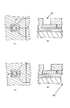
まず、図12(a)に示すように、例えばSiチップ上にパターニング処理等により複数のヒータ303およびこれらヒータ303に電圧を印加するための所定の配線(不図示)を設けることにより素子基板301を形成する。次に、図12(b)に示すように、前記素子基板301上に、前記可動部材310が、供給口305側に変位することを制限するための突起状障壁313’を形成するために、オリフィス基板312と同じ組成である透明なネガ型樹脂層313を約5.0μm塗布する。
【0026】
その後、図12(c)に示すように、UV光を用いて、突起型形状になるようなパターン(突起状障壁)313’を形成する。次に、図12(d),図12(e)に示すように、前記基板301上に、下樹脂層308および上樹脂層309を連続して、スピンコート法によりそれぞれ塗布する。下樹脂層308および上樹脂層309は、波長が330nm以下の紫外光であるDeep−UV光(以下、DUV光と称する。)を照射することによって、分子中の結合が破壊されて溶解可能な樹脂を用いる。
【0027】
また、下樹脂層308として、脱水縮合反応による熱架橋型の樹脂材を用いることで、上樹脂層309をスピンコート法によって塗布する際に、下樹脂層308と上層樹脂309の各樹脂層間で相互に溶融することが防止されている。下樹脂層308としては、例えばメタクリル酸メチル(MMA)とメタクリル酸(MAA)をラジカル重合させて、ポリマー化させた2元共重合体(P(MMA−MAA)=90:10)をシクロヘキサノン溶媒で溶解した液を使用した。
【0028】
また、上樹脂層309としては、例えばポリメチルイソプロペニルケトン(PMIPK)をシクロヘキサノン溶媒で溶解した液を使用した。下樹脂層として使用した2元共重合体(P(MMA−MAA))は脱水縮合反応は、180〜200℃で、30分〜2時間加熱することにより、脱水縮合反応によって、より強固な架橋膜を形成することができる。尚、この架橋膜は、溶媒不溶型になっているが、DUV光などの電子線を照射することで、分解反応が起こり、低分子化が進み、電子線が照射した部分のみ、溶媒可溶性となる。
【0029】
その後、図13(a)に示すように、DUV光を照射する露光装置を用いて、この露光装置に波長260nm未満のDUV光を遮断するフィルターを装着することで、260nm以上のみを透過させる波長選択手段を用いて、波長が260〜330nm付近のNear−UV光(以下、NUV光と称する。)を照射させて、上樹脂層309を露光および現像することによって、上樹脂層309により所望のノズルパターン309’を形成する。上樹脂層309によりノズルパターン309’を形成する際、上樹脂層309と下樹脂層308とは、波長260〜330nm付近のNUV光に対する感度比が約40:1以上の差であるため、下樹脂層308が感光されることなく、下樹脂層309:P(MMA−MAA)が分解されることはない。又、下樹脂層308は、熱架橋膜であるために、上樹脂層を現像時の現像液に溶解することもない。
【0030】
その後、図13(b)に示すように、上述した露光装置で波長210〜330nmのDUV光を照射させて、下樹脂層を露光および現像することによって、下樹脂層308により所望のノズルパターン308’を形成する。下樹脂層308に使用したP(MMA−MAA)材料は、解像力が高く、5〜20μm程度の厚さでも、側壁の傾斜角は、0〜5°程度のトレンチ構造に形成することが可能である。
その後、ノズルパターン308’,309’が形成されて、DUV光によって、分子中の架橋結合が破壊されて溶解可能な上樹脂層309および下樹脂層308上に、図13(c)に示すように、オリフィス基板となる透明な被覆樹脂層312を塗布する。
【0031】
その後、図13(d)に示すように、この被覆樹脂層312に、露光装置でUV光を照射させて、吐出口307に相当する部分を露光および現像して除去することにより、オリフィス基板を形成する。該オリフィス基板に形成する吐出口部の側壁の傾斜は、液滴を前記素子基板の主面に直交する平面に対し、なるべく0°付近で形成することが望ましい。又、0〜10°程度であれば、液滴の吐出特性について、大きな問題は発生しない。
【0032】
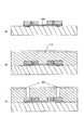
その後、図14(a)に示すように、化学エッチングを行う際のオリフィスプレート面側を保護するために、有機系樹脂膜314を塗布する。そして、図14(b)に示すように、素子基板301の裏面に化学的なエッチング処理等を行うことによって、素子基板301に供給口305を形成する。化学的なエッチング処理としては、例えば、強アルカリ溶液(KOH,NaOH,TMAH)を用いた異方性エッチング処理が適用される。
【0033】
その後、図14(c)に示すように、波長330nm以下のDUV光を素子基板301の主面側から被覆樹脂層312を透過させて照射することにより、素子基板301とオリフィス基板312との間に位置するノズル型材である上樹脂層309,下樹脂層308をそれぞれ溶出させる。
【0034】
したがって、吐出口307および供給口305と、これらを連通する供給路(ノズル流路)306内の、ヒータ303と供給口305との間に可動部材310が形成され、該可動部材310と供給口305との間に該可動部材の供給口側への変位を制限する突起状障壁が形成されたノズル流路306を備えるチップが得られる。このチップと、ヒータ303を駆動するための配線基板(図示せず)等とを電気的に接続することにより、記録ヘッドが得られる。
【0035】
なお、上述した記録ヘッドの製造方法によれば、DUV光によって分子中の架橋結合が破壊されて溶解可能な上樹脂層309および下樹脂層308を、素子基板の厚み方向に対して更に階層構造にすることによって、ノズル内に3段以上の段差状に形成された制御部を設けることが可能とされる。例えば、上樹脂層の更に上層側に、波長400nm以上の光に感度を有する樹脂材料を用いて、多段階のノズル構造を形成することができる。
【0036】
[実施例4]
以下に本発明に係るインクジェットプリントヘッドの製造方法の別の一例を図15〜図17に従って、詳細に示す。
まず、図15(a)に示すように、Siチップ上にパターニング等によって複数の電気熱変換素子(ヒータ)403およびそれらを駆動するための必要な配線(不図示)が施された基板401を用意する。
【0037】
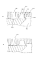
その後、図15(b),図15(c)に示すように、Deep−UV光(300nm以下の紫外光)によって、分子中の架橋結合が破壊され、溶解可能な樹脂層408及び、409を連続で、スピンコート法により、塗布する。その際、下層となる樹脂層408には、熱架橋型樹脂を用いることで、上層の樹脂409をスピンコート法により、塗布する際に、下層樹脂と上層の樹脂間で相互に溶融することを防止した。この時、下層樹脂408としては、P(MMA−MAC=90:10)をシクロヘキサノン溶媒で溶解した液を使用した。又、上層樹脂としては、PMIPKをシクロヘキサノン溶媒で溶解した液を使用した。その後、Deep−UV光を用いた露光装置(キヤノン製:PLA521)により、CM290を装着し、290nm近傍のDeep−UV光のみで、上層樹脂409を露光し現像することで、図15(d)に示すようなノズルパターン409’を形成した。その際、下層樹脂408と上層樹脂409とでは、290nm近傍のDeep−UV光に対する感度比が、約50:1以上の差があるために、下層樹脂が、感光し、パターニングされることは無い。
【0038】
次に、同じ露光装置で、CM250を装着し、250nm近傍のDeep−UV光のみで、下層樹脂を露光し現像することで、図16(a)に示すようにノズルパターンを形成した。更に、このようなノズルパターンが形成され、Deep−UV光によって、分子中の架橋結合が破壊され、溶解可能な樹脂層408及び、409上に、被覆樹脂層412を形成させ(図16(b))、吐出口407に相当する部分を、UV光を用いた露光装置(キヤノン製:MPA−600)により、露光して現像し、除去した(図16(c))。
次に、図17(a)に示すように、化学エッチングを行う際に吐出口面側を保護するために、有機系樹脂膜414を塗布した。そして、図17(b)に示すように、基板401を裏面から化学的にエッチングするなどして、供給口を形成した。より具体的には、強アルカリ溶液(KOH,NaOH,TMAH)を用いた異方性エッチングによって供給口405を形成した。
【0039】
最後に、基板401の表面から、前記被覆樹脂層412を透して、Deep−UV光(300nm以下の紫外光)を照射し、ノズルパターンである樹脂層408’,409’を溶出させた。これにより、吐出口407、供給口405とそれらに連通する段差形状を有するノズル406を備え、該ノズル406内の電気熱変換素子403と供給口405との間に可動部材410及び可動部材の供給口側への変位を制限するための制限部412’を備えたインクジェットヘッドチップを得ることができる。このチップに電気熱変換素子を駆動するための配線基板と電気的接合等を行うことにより、本発明のインクジェット記録ヘッドを得ることができる。
【0040】
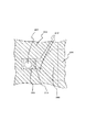
図18は、上記インクジェット記録ヘッドのノズル部分の平面図を示している(図17(c)は図18のA−A’線における断面図に対応する。)。前記可動部材410は、ヒータ面上で気泡が発生した時に、該可動部材410から吐出口までの部分を略密閉状態にするために、該可動部材410が、気泡発生時にインク供給口405側へ変位することを制限できるストッパー(障壁)がノズル流路406の側壁の一部412’を突出させることによって形成されている。この障壁は、リフィルの際に供給口から吐出口側へのインクの流れをなるべく妨げないように、寸法的に小さなものが好ましい。更に、可動部材とノズル壁との間にも、フォトリソグラフィープロセス法により作成できる微小な隙間を有している。この隙間は、可動部材が変位するのに、可能な量であれば、なるべく微小であることが望ましい。
【0041】
また、図19に示すインクジェット記録ヘッドのように、本実施例のように、可動部材510とインク供給口505との間の、ノズル流路506の側壁の一部512’を突出させるばかりでなく、実施例3のように基板上に突起型障壁513’を形成すれば、気泡の成長時により効果的に可動部材510によってインク供給口505側へのインクの流れをより抑制することができ、さらに吐出性能を高めることができる。
【0042】
上記のように作成されたインクジェット記録ヘッド(液体吐出ヘッド)の動作について、図20を参照して、簡単に説明する。
まず、図20(a)で示すように、初期状態では、吐出口607の下方にヒータ603が配され、ヒータから吐出口への吐出口流路と、ヒータからインク供給口に繋がるノズル606とは、L字型になっている。ノズル内には、可動部材610が、ヒータを備えた基板のノズル側の面に対して垂直方向に配されている。そして、図20(b)で示すように、ヒータ部で気泡615が発生すると同時に、発生する圧力波、および、インクの流れに伴って、可動部材610が、インク供給口605側に少し傾いて、可動部材、HB(基板)上に形成した突起型障壁613’、および、該可動部材後方に形成されているストッパー形状の構造物612’によって、吐出口から該可動部材までのノズル内部を略密閉状態に維持する。
【0043】
これにより、ヒータ面上の圧力が殆ど吐出口側へ集中し、吐出するインク滴616を効率良く飛翔させることができる。尚、可動部材と突起型障壁613’との間には、微小の隙間が存在するが、前述の略密閉状態になるためには、可能な限り微小であることが望ましい。又、可動部材610とノズル606の側壁との間にも、微小な隙間が存在する。
【0044】
次に、図21(a)で示すように、ノズル内が、可動部材610と突起型障壁613’とストッパー形状の構造物612’によって、略密閉状態になっているので、気泡の成長は、殆ど吐出口側に大きく成長し、より安定的に、且つ、より効率良くインク滴616を吐出口から飛翔させることができる。そして、図21(b)で示すように、ヒータ面上で、気泡が消泡し始めると、前記可動部材610が、吐出口607側に変位し始める。続いて、可動部材610が吐出口側に大きく変位する。この際、可動部材が吐出口側へ変位する量は、気泡成長時に可動部材がインク供給口側へ変位する量よりも大きい。
【0045】
これにより、インク供給口605から複数のインクノズル内へ高速リフィルが行われる。尚、気泡発生時のインク供給口605側へのインクの流れが、前記可動部材610、HB(基板)601上に形成した突起型障壁613’および、該可動部材後方に形成されているストッパー形状の構造物612’によって、阻害されているので、ノズル606内にリフィルされるインク量を、飛翔したインク体積に近い最低限のインク量とすることができる。
【0046】
【発明の効果】
本発明によれば、インク供給口と吐出口の間におけるノズル流路に可動部材を形成し、吐出性能を維持し周波数特性を向上することを可能とした高密度、高精度、高信頼性のインクジェット記録ヘッドの作成方法を実現することができる。
【図面の簡単な説明】
【図1】 図1(a)は、本発明の実施例1におけるインクジェット記録ヘッドの作成方法を説明するための模式的な断面図である。図1(b)は図1(a)のA−A’線における断面図である。図1(c)は、本発明の実施例1におけるインクジェット記録ヘッドの作成方法の図1(a)の工程に続く工程を説明するための模式的な断面図である。図1(d)は図1(c)のA−A’線における断面図である。
【図2】 図2(a)は、本発明の実施例1におけるインクジェット記録ヘッドの作成方法の図1(c)の工程に続く工程を説明するための模式的な断面図である。図2(b)は図2(a)のA−A’線における断面図である。図2(c)は、本発明の実施例1におけるインクジェット記録ヘッドの作成方法の図2(a)の工程に続く工程を説明するための模式的な断面図である。図2(d)は図2(c)のA−A’線における断面図である。
【図3】 図3(a)は、本発明の実施例1におけるインクジェット記録ヘッドの作成方法の図2(c)の工程に続く工程を説明するための模式的な断面図である。図3(b)は図3(a)のA−A’線における断面図である。図3(c)は、本発明の実施例1におけるインクジェット記録ヘッドの作成方法の図3(a)の工程に続く工程を説明するための模式的な断面図である。図3(d)は図3(c)のA−A’線における断面図である。
【図4】 図4(a)は、本発明の実施例1におけるインクジェット記録ヘッドの作成方法の図3(c)の工程に続く工程を説明するための模式的な断面図である。図4(b)は図4(a)のA−A’線における断面図である。図4(c)は、本発明の実施例1におけるインクジェット記録ヘッドの作成方法の図4(a)の工程に続く工程を説明するための模式的な断面図である。図4(d)は図4(c)のA−A’線における断面図である。
【図5】 図5(a)は、本発明の実施例1におけるインクジェット記録ヘッドの作成方法の図4(c)の工程に続く工程を説明するための模式的な断面図である。図5(b)は図5(a)のA−A’線における断面図である。
【図6】 図6(a)は、本発明の実施例2におけるインクジェット記録ヘッドの作成方法を説明するための模式的な断面図である。図6(b)は図6(a)のA−A’線における断面図である。図6(c)は、本発明の実施例2におけるインクジェット記録ヘッドの作成方法の図6(a)の工程に続く工程を説明するための模式的な断面図である。図6(d)は図6(c)のA−A’線における断面図である。
【図7】 図7(a)は、本発明の実施例2におけるインクジェット記録ヘッドの作成方法の図6(c)の工程に続く工程を説明するための模式的な断面図である。図7(b)は図7(a)のA−A’線における断面図である。図7(c)は、本発明の実施例1におけるインクジェット記録ヘッドの作成方法の図7(a)の工程に続く工程を説明するための模式的な断面図である。図7(d)は図7(c)のA−A’線における断面図である。
【図8】 図8(a)は、本発明の実施例2におけるインクジェット記録ヘッドの作成方法の図7(c)の工程に続く工程を説明するための模式的な断面図である。図8(b)は図8(a)のA−A’線における断面図である。図8(c)は、本発明の実施例1におけるインクジェット記録ヘッドの作成方法の図8(a)の工程に続く工程を説明するための模式的な断面図である。図8(d)は図8(c)のA−A’線における断面図である。
【図9】 図9(a)は、本発明の実施例2におけるインクジェット記録ヘッドの作成方法の図8(c)の工程に続く工程を説明するための模式的な断面図である。図9(b)は図9(a)のA−A’線における断面図である。
【図10】 本発明の実施例2における図7(a)の工程において用いるマスクパターンを示す平面図である。
【図11】 本発明の実施例2の変形例を示すインクジェット記録ヘッドの平面図である。
【図12】 図12(a)は、本発明の実施例3におけるインクジェット記録ヘッドの作成方法を説明するための模式的な断面図である。図12(b)は、本発明の実施例3におけるインクジェット記録ヘッドの作成方法の図12(a)の工程に続く工程を説明するための模式的な断面図である。図12(c)は、本発明の実施例3におけるインクジェット記録ヘッドの作成方法の図12(b)の工程に続く工程を説明するための模式的な断面図である。図12(d)は、本発明の実施例3におけるインクジェット記録ヘッドの作成方法の図12(c)の工程に続く工程を説明するための模式的な断面図である。図12(e)は、本発明の実施例3におけるインクジェット記録ヘッドの作成方法の図12(d)の工程に続く工程を説明するための模式的な断面図である。
【図13】 図13(a)は、本発明の実施例3におけるインクジェット記録ヘッドの作成方法の図12(e)の工程に続く工程を説明するための模式的な断面図である。図13(b)は、本発明の実施例3におけるインクジェット記録ヘッドの作成方法の図13(a)の工程に続く工程を説明するための模式的な断面図である。図13(c)は、本発明の実施例3におけるインクジェット記録ヘッドの作成方法の図13(b)の工程に続く工程を説明するための模式的な断面図である。図13(d)は、本発明の実施例3におけるインクジェット記録ヘッドの作成方法の図13(c)の工程に続く工程を説明するための模式的な断面図である。
【図14】 図14(a)は、本発明の実施例3におけるインクジェット記録ヘッドの作成方法の図13(d)の工程に続く工程を説明するための模式的な断面図である。図14(b)は、本発明の実施例3におけるインクジェット記録ヘッドの作成方法の図14(a)の工程に続く工程を説明するための模式的な断面図である。図14(c)は、本発明の実施例3におけるインクジェット記録ヘッドの作成方法の図14(b)の工程に続く工程を説明するための模式的な断面図である。
【図15】 図15(a)は、本発明の実施例4におけるインクジェット記録ヘッドの作成方法を説明するための模式的な断面図である。図15(b)は、本発明の実施例3におけるインクジェット記録ヘッドの作成方法の図15(a)の工程に続く工程を説明するための模式的な断面図である。図15(c)は、本発明の実施例3におけるインクジェット記録ヘッドの作成方法の図15(b)の工程に続く工程を説明するための模式的な断面図である。図15(d)は、本発明の実施例3におけるインクジェット記録ヘッドの作成方法の図15(c)の工程に続く工程を説明するための模式的な断面図である。
【図16】 図16(a)は、本発明の実施例4におけるインクジェット記録ヘッドの作成方法の図15(d)の工程に続く工程を説明するための模式的な断面図である。図16(b)は、本発明の実施例3におけるインクジェット記録ヘッドの作成方法の図16(a)の工程に続く工程を説明するための模式的な断面図である。図16(c)は、本発明の実施例3におけるインクジェット記録ヘッドの作成方法の図16(b)の工程に続く工程を説明するための模式的な断面図である。
【図17】 図17(a)は、本発明の実施例4におけるインクジェット記録ヘッドの作成方法の図16(c)の工程に続く工程を説明するための模式的な断面図である。図17(b)は、本発明の実施例3におけるインクジェット記録ヘッドの作成方法の図17(a)の工程に続く工程を説明するための模式的な断面図である。図17(c)は、本発明の実施例3におけるインクジェット記録ヘッドの作成方法の図17(b)の工程に続く工程を説明するための模式的な断面図である。
【図18】 図18は、本発明の実施例4におけるインクジェット記録ヘッドのノズル部分を示す平面図である。
【図19】 図19(a)は、本発明の実施例4の変形例におけるインクジェット記録ヘッドの模式的な断面図である。図19(b)は、本発明の実施例4の変形例によって得られたヘッドチップの模式的な断面図である。
【図20】 図20は、本発明のインクジェット記録ヘッドの作成方法によって作成されたインクジェット記録ヘッドを用いてインク滴を吐出する吐出動作を説明するための模式的な断面図である。
【図21】 図21は、図20に引き続き、本発明のインクジェット記録ヘッドの作成方法によって作成されたインクジェット記録ヘッドを用いてインク滴を吐出する吐出動作を説明するための模式的な断面図である。
【図22】 図22は、本発明のインクジェット記録ヘッドの作成方法によって作成されたインクジェット記録ヘッドを示す模式的な斜視図である。
【符号の説明】
1:基板
3:発熱抵抗体
5:インク供給口
7:吐出口
12:インク流路を構成する部材
101:基板
102:蓄熱層
103:ヒータ(発熱抵抗部)
104:保護層
105:インク供給口
106:ノズル
107:吐出口
108:第一の型レジスト
109:第二の型レジスト
110:弁
111:型レジストによる弁形状形成部
112:感光性エポキシ材
201:基板
202:蓄熱層
203:ヒータ(発熱抵抗部)
204:保護層
205:インク供給口
206:ノズル
207:吐出口
208:フォトレジスト
210:可動部材
301:素子基板
303:ヒータ
305:供給口
306:供給路
307:吐出口
308:下樹脂層
308’:ノズルパターン
309:上樹脂層
309’:ノズルパターン
310:可動部材
312:オリフィス基板
313:ネガ型樹脂層
313’:突起状障壁
401:基板
403:電気熱変換素子(ヒータ)
405:供給口
406:ノズル
408:下樹脂層
409:上樹脂層
410:可動部材
505:インク供給口
506:ノズル流路
605:インク供給口
606:ノズル
610:可動部材
612’:ストッパー形状の構造物
613’:突起型障壁
615:気泡[0001]
BACKGROUND OF THE INVENTION
The present invention relates to a method for producing an ink jet recording head that forms liquid droplets by ejecting liquid from an orifice (discharge port).To the lawRelated.
[0002]
[Prior art]
With respect to this type of ink jet recording head that forms liquid droplets by ejecting liquid from an orifice, for example, an ink jet recording method described in Japanese Patent Application Laid-Open No. 54-51837 uses thermal energy to act on a liquid to produce liquid droplets. This method is different from other ink jet recording methods in that it provides a driving force for ejection.
[0003]
That is, in the recording method disclosed in the above-mentioned publication, the liquid subjected to the action of thermal energy is heated up to generate bubbles, and droplets are discharged from the orifice at the tip of the recording head by the action force based on the generation of bubbles. It is characterized in that information is recorded by forming the droplets on the recording member.
[0004]
A recording head applied to this recording method generally includes an orifice provided for discharging a liquid, and a heat acting portion that is a portion where heat energy for discharging a droplet communicated with the orifice acts on the liquid. A liquid discharge portion having a liquid flow path having a liquid crystal structure as a part, a heat generation resistance layer as a heat conversion body which is a means for generating thermal energy, an upper protective layer for protecting it from ink, and a lower layer for storing heat It has.
[0005]
[Problems to be solved by the invention]
In order to improve the printing speed of an ink jet recording head that obtains the driving force for droplet discharge by applying the above-described thermal energy to the liquid, there is an improvement in frequency characteristics as performance required for the ink jet recording head. In order to improve this frequency characteristic, it is necessary to improve the refill performance of the ink after discharging the droplet. In order to improve the ink refill performance, it is necessary to reduce the flow resistance from the ink supply port to the discharge port.
[0006]
However, if the flow resistance is reduced, the foaming pressure escapes to the ink supply port side, the discharge speed is lowered and the stability is lost, the discharge performance is deteriorated, and the printing is deteriorated. For this reason, it has been very difficult to maintain the discharge performance and improve the frequency characteristics.
[0007]
Furthermore, in order to meet the market demand for high image quality in recent years, in order to achieve high resolution and printed matter with small droplets, the inkjet print heads are arranged in high density and from the discharge port. It is necessary to fly a minute droplet.
[0008]
On the other hand, it has been proposed to improve frequency characteristics while maintaining ejection performance by providing a movable member that is a so-called fluidic diode in the nozzle flow path between the ink supply port and the ejection port. However, in such a conventional ink jet recording head, the movable member may be peeled off or destroyed.
[0009]
Therefore, the present invention solves the above-mentioned problems, forms a movable member in the nozzle flow path between the ink supply port and the discharge port, maintains the discharge performance and improves the frequency characteristics, and achieves high density and high How to make an inkjet recording head with high accuracy and high reliabilityThe lawThe purpose is to provide.
[0010]
[Means for Solving the Problems]
In order to solve the above problems, the present invention provides the following (1) to (4How to make an inkjet recording head configured asThe lawIt is to provide.
(1) A heating resistor, an ink discharge port provided corresponding to the heating resistor, and a nozzle channel communicating with the ink discharge port, and the heating resistor in the nozzle channel A movable member is formed between the body and an ink supply port for supplying ink into the nozzle channel, and bubbles generated in the ink in the nozzle channel due to heat generated by the heating resistor In the method of creating an ink jet recording head for discharging ink from the ink discharge port using
Preparing a substrate provided with the heating resistor;
Applying a first resin to be a first mold material for forming the nozzle flow path and the movable member on the substrate;
Forming the first mold material with the first resin;
Applying a second resin for forming the nozzle flow path and the movable member on the substrate so as to cover the first mold material;
And a step of removing the first mold member.
(2) The first resin is a photoresist, and in the step of forming the first mold material, the first mold material is formed using a mask pattern having a width less than a resolution limit of the photoresist. The method for producing an ink jet recording head according to the above (1), comprising a step of forming a portion for forming the movable member.
(3) Before the step of applying the first resin, the method further includes a step of applying a third resin to be a second mold material for forming the nozzle flow path on the substrate,
The step of applying the first resin is a step of applying the first resin on the substrate so as to cover the second mold material with the first resin.
A method for producing an ink jet recording head according to (1) above.
(4) Before applying the first resin on the substrate, on the substrate, at a position corresponding to between the movable member and the supply port.For limiting the displacement of the movable member toward the supply port.The method for producing an ink jet recording head according to (1), further comprising a step of forming a protruding barrier..
[0011]
DETAILED DESCRIPTION OF THE INVENTION
According to the method for producing an ink jet recording head to which the above configuration is applied, the movable member can form a mold at the time of patterning the nozzle mold material, so that the movable member and the nozzle flow path can be formed with high density and high accuracy by photolithography. This makes it possible to produce a high-density, high-precision inkjet recording head.
Further, as a method of forming the movable member, a portion for forming the movable member of the first mold material is formed using a mask pattern having a width less than the resolution limit of the first resin, and the portion If the movable member is formed of a resin to be applied later, the mold material of the nozzle flow path and the movable member forming portion can be formed with the same mask. Therefore, the nozzle channel and the movable member can be formed with a mask creation accuracy. Further, one patterning step can be omitted, and the cost can be reduced.
In addition, according to the ink jet recording head to which the above configuration is applied, the movable member can be formed of the same material as that of the ink flow path, and the movable member and the ink flow path are integrally formed. Compared with the method of attaching the member as a separate part, the movable member is less likely to be peeled off or broken, and an ink jet head with high reliability can be provided.
[0012]
【Example】
Examples of the present invention will be described below. FIG. 22 is a schematic perspective view of the ink jet recording head in the embodiment of the present invention. A
[0013]
[Example 1]
A method for producing an ink jet recording head in Example 1 of the present invention will be described with reference to FIGS.
First, the
Next, 3 μm of the first mold resist 108 is applied (FIGS. 1C and 1D).
Next, the first mold resist 108 is patterned in the shape of the nozzle flow path by exposure and development (FIGS. 2A and 2B).
[0014]
Next, 12 μm of a second type resist 109 is applied on the patterned layer (FIGS. 2C and 2D).
Next, the second mold resist 109 is patterned into a nozzle channel shape and a movable member shape 111 (5 μm × 25 μm) by exposure and development (FIGS. 3A and 3B).
Next, the photosensitive
[0015]
Next, the
Next, the
[0016]
Finally, the resist that has become the mold material is removed using a stripping solution, and the head chip with the
Then, an ink jet recording head is completed by electrical mounting for supplying electricity for generating heat from a tube for supplying ink and a heater.
[0017]
The head thus completed has high frequency response and good ejection performance. Therefore, good printing can be performed at high speed.
In addition, since the patterning for forming the movable member is a photolithography method, the movable member can be formed with high accuracy, and the movable member can be arranged with high accuracy with respect to the heater, the nozzle, and the discharge port. . Therefore, it is possible to sufficiently cope with future reduction in droplet size and increase in density.
[0018]
Furthermore, because it can be formed integrally with the epoxy material that forms the nozzle and discharge port, it does not easily peel off during long-term use, and by selecting an epoxy material that is ink-resistant, solute and swelling from the epoxy material, etc. Does not occur.
Therefore, a highly reliable head can be provided.
[0019]
[Example 2]
A method for producing an ink jet recording head in Example 2 of the present invention will be described with reference to FIGS.
First, in the same manner as in Example 1, a
[0020]
Next, 20 μm of a
Next, exposure and development are performed using a mask having a nozzle flow path shape and a movable member shape (2 μm × 25 μm) mask pattern as shown in FIG. 10 to form a pattern.
Since the
[0021]
When the mask is formed with a resolution lower than the limit, patterning is performed up to the middle of the resist as shown in FIGS. 7 (a) and 7 (b). Therefore, since the pattern does not reach the substrate, it can function as a mold for a movable member that can move.
Next, a photosensitive epoxy for forming the
Next, the discharge port is formed by patterning into a shape having a diameter of 18 μm by exposure and development (FIGS. 8A and 8B).
[0022]
Next, an
Finally, the resist that has become the mold material is removed using a stripping solution to complete a substrate with a nozzle (FIGS. 9A and 9B).
Then, an ink jet recording head is completed by connecting a tube (not shown) for supplying ink and connecting an electric wiring board (not shown) for supplying electricity for generating heat from the
The head thus completed has high frequency response and good ejection performance. Therefore, good printing can be performed at high speed.
[0023]
In addition to the effects of the first embodiment, it is possible to reduce the cost by eliminating one step of applying, exposing and developing the mold resist.
Further, since the
Further, the
[0024]
Further, as shown in FIG. 11, the nozzle pattern is formed so that a part of the
[0025]
[Example 3]
Another example of a method for producing an ink jet recording head (ink jet print head) in Example 3 of the present invention will be described with reference to FIGS.
First, as shown in FIG. 12A, a plurality of
[0026]
Thereafter, as shown in FIG. 12C, a pattern (projection-shaped barrier) 313 ′ having a projection shape is formed using UV light. Next, as shown in FIGS. 12D and 12E, a
[0027]
Further, by using a heat-crosslinking type resin material by a dehydration condensation reaction as the
[0028]
Further, as the
[0029]
Thereafter, as shown in FIG. 13 (a), by using an exposure apparatus that irradiates DUV light, a filter that blocks DUV light having a wavelength of less than 260 nm is attached to the exposure apparatus, so that only 260 nm or more is transmitted. The
[0030]
Thereafter, as shown in FIG. 13B, the
After that,
[0031]
Thereafter, as shown in FIG. 13D, the
[0032]
Thereafter, as shown in FIG. 14A, an
[0033]
Thereafter, as shown in FIG. 14C, the DUV light having a wavelength of 330 nm or less is irradiated from the main surface side of the
[0034]
Therefore, the movable member 310 is formed between the
[0035]
According to the recording head manufacturing method described above, the
[0036]
[Example 4]
Hereinafter, another example of the method for producing an ink jet print head according to the present invention will be described in detail with reference to FIGS.
First, as shown in FIG. 15A, a
[0037]
Thereafter, as shown in FIG. 15B and FIG. 15C, deep-resin resin layers 408 and 409 are broken by deep-UV light (ultraviolet light of 300 nm or less) and the cross-linking bond in the molecule is broken. It is continuously applied by spin coating. At that time, by using a heat-crosslinking resin for the
[0038]
Next, with the same exposure apparatus, the CM 250 was mounted, and the lower layer resin was exposed and developed only with deep-UV light in the vicinity of 250 nm, thereby forming a nozzle pattern as shown in FIG. Furthermore, such a nozzle pattern is formed, and the crosslinking bond in the molecule is broken by Deep-UV light, so that the covering
Next, as shown in FIG. 17A, an
[0039]
Finally, Deep-UV light (ultraviolet light of 300 nm or less) was irradiated from the surface of the
[0040]
FIG. 18 is a plan view of the nozzle portion of the ink jet recording head (FIG. 17C corresponds to a cross-sectional view taken along the line A-A ′ of FIG. 18). The
[0041]
Further, as in the case of the ink jet recording head shown in FIG. 19, not only the
[0042]
Created as aboveTaThe operation of the ink jet recording head (liquid ejection head) will be briefly described with reference to FIG.
First, as shown in FIG. 20A, in the initial state, a heater is provided below the discharge port 607.6No. 03 is disposed, and the discharge port flow path from the heater to the discharge port and the
[0043]
Thereby, the pressure on the heater surface is almost concentrated on the ejection port side, and the ejected
[0044]
Next, as shown in FIG. 21A, the inside of the nozzle is substantially sealed by the
[0045]
As a result, high-speed refill is performed from the
[0046]
【The invention's effect】
According to the present invention, a movable member is formed in the nozzle flow path between the ink supply port and the discharge port, and it is possible to maintain the discharge performance and improve the frequency characteristics, thereby achieving high density, high accuracy, and high reliability. How to make an inkjet recording headThe lawCan be realized.
[Brief description of the drawings]
FIG. 1A is a schematic cross-sectional view for explaining a method for producing an ink jet recording head in Example 1 of the present invention. FIG. 1B is a cross-sectional view taken along the line A-A ′ of FIG. FIG. 1C is a schematic cross-sectional view for explaining a process following the process of FIG. 1A of the method for producing the ink jet recording head in the first embodiment of the present invention. FIG. 1D is a cross-sectional view taken along the line A-A ′ of FIG.
FIG. 2A is a schematic cross-sectional view for explaining a step following the step of FIG. 1C of the method for producing the ink jet recording head in the embodiment 1 of the present invention. FIG. 2B is a cross-sectional view taken along the line A-A ′ of FIG. FIG. 2C is a schematic cross-sectional view for explaining a process following the process of FIG. 2A of the method for producing the ink jet recording head in the first embodiment of the present invention. FIG. 2D is a cross-sectional view taken along the line A-A ′ of FIG.
FIG. 3A is a schematic cross-sectional view for explaining a step following the step of FIG. 2C of the method for producing the ink jet recording head in the embodiment 1 of the present invention. FIG. 3B is a cross-sectional view taken along the line A-A ′ of FIG. FIG. 3C is a schematic cross-sectional view for explaining a process following the process of FIG. 3A of the method for producing the ink jet recording head in the first embodiment of the present invention. FIG. 3D is a cross-sectional view taken along the line A-A ′ of FIG.
4A is a schematic cross-sectional view for explaining a process following the process of FIG. 3C of the method for producing the ink jet recording head according to the first embodiment of the present invention. FIG. FIG. 4B is a cross-sectional view taken along the line A-A ′ of FIG. FIG. 4C is a schematic cross-sectional view for explaining a process following the process of FIG. 4A of the method for producing the ink jet recording head in the first embodiment of the present invention. FIG. 4D is a cross-sectional view taken along the line A-A ′ of FIG.
FIG. 5A is a schematic cross-sectional view for explaining a process following the process of FIG. 4C in the method for producing the ink jet recording head in the embodiment 1 of the present invention. FIG. 5B is a cross-sectional view taken along the line A-A ′ of FIG.
FIG. 6A is a schematic cross-sectional view for explaining a method for producing an ink jet recording head in Example 2 of the present invention. FIG. 6B is a cross-sectional view taken along the line A-A ′ of FIG. FIG. 6C is a schematic cross-sectional view for explaining a process following the process of FIG. 6A of the method for producing the ink jet recording head in the second embodiment of the present invention. FIG. 6D is a cross-sectional view taken along the line A-A ′ of FIG.
FIG. 7A is a schematic cross-sectional view for explaining a process following the process of FIG. 6C of the method for producing the ink jet recording head in the second embodiment of the present invention. FIG. 7B is a cross-sectional view taken along the line A-A ′ of FIG. FIG. 7C is a schematic cross-sectional view for explaining a process following the process of FIG. 7A of the method for producing the ink jet recording head according to the first embodiment of the present invention. FIG. 7D is a cross-sectional view taken along the line A-A ′ of FIG.
FIG. 8A is a schematic cross-sectional view for explaining a process following the process of FIG. 7C of the method for producing the ink jet recording head in the second embodiment of the present invention. FIG. 8B is a cross-sectional view taken along line A-A ′ of FIG. FIG. 8C is a schematic cross-sectional view for explaining a process following the process of FIG. 8A of the method for producing the ink jet recording head in the first embodiment of the present invention. FIG. 8D is a cross-sectional view taken along the line A-A ′ of FIG.
FIG. 9A is a schematic cross-sectional view for explaining a process following the process of FIG. 8C of the method for producing the ink jet recording head in the second embodiment of the present invention. FIG. 9B is a cross-sectional view taken along the line A-A ′ of FIG.
FIG. 10 is a plan view showing a mask pattern used in the step of FIG. 7A in Embodiment 2 of the present invention.
FIG. 11 is a plan view of an ink jet recording head showing a modification of the second embodiment of the present invention.
FIG. 12A is a schematic cross-sectional view for explaining a method for producing an ink jet recording head in Example 3 of the present invention. FIG. 12B is a schematic cross-sectional view for explaining a process following the process of FIG. 12A of the method for producing the ink jet recording head in the third embodiment of the present invention. FIG. 12C is a schematic cross-sectional view for explaining a process following the process of FIG. 12B of the method for producing the ink jet recording head in the third embodiment of the present invention. FIG. 12D is a schematic cross-sectional view for explaining a process following the process of FIG. 12C of the method for producing the ink jet recording head in the third embodiment of the present invention. FIG. 12E is a schematic cross-sectional view for explaining a process following the process of FIG. 12D of the method for producing the ink jet recording head in the third embodiment of the present invention.
FIG. 13A is a schematic cross-sectional view for explaining a process following the process of FIG. 12E of the method for producing an ink jet recording head according to the third embodiment of the present invention. FIG. 13B is a schematic cross-sectional view for explaining a process following the process of FIG. 13A of the method for producing the ink jet recording head in the third embodiment of the present invention. FIG. 13C is a schematic cross-sectional view for explaining a process following the process of FIG. 13B of the method for producing the ink jet recording head in the third embodiment of the present invention. FIG. 13D is a schematic cross-sectional view for explaining a process following the process of FIG. 13C of the method for producing the ink jet recording head in the third embodiment of the present invention.
FIG. 14A is a schematic cross-sectional view for explaining a step following the step of FIG. 13D of the method for producing the ink jet recording head in the embodiment 3 of the present invention. FIG. 14B is a schematic cross-sectional view for explaining a process following the process of FIG. 14A of the method for producing the ink jet recording head in the third embodiment of the present invention. FIG. 14C is a schematic cross-sectional view for explaining a process following the process of FIG. 14B of the method for producing the ink jet recording head in the third embodiment of the present invention.
FIG. 15A is a schematic cross-sectional view for explaining a method for producing an ink jet recording head in Example 4 of the present invention. FIG. 15B is a schematic cross-sectional view for explaining a process following the process of FIG. 15A of the method for producing the ink jet recording head in the third embodiment of the present invention. FIG. 15C is a schematic cross-sectional view for explaining a process subsequent to the process of FIG. 15B of the method for producing the ink jet recording head in the third embodiment of the present invention. FIG. 15D is a schematic cross-sectional view for explaining a process following the process of FIG. 15C of the method for producing the ink jet recording head in the third embodiment of the present invention.
FIG. 16A is a schematic cross-sectional view for explaining a process following the process of FIG. 15D of the method for producing the ink jet recording head according to the fourth embodiment of the present invention. FIG. 16B is a schematic cross-sectional view for explaining a step following the step of FIG. 16A of the method for producing the ink jet recording head in the third embodiment of the present invention. FIG. 16C is a schematic cross-sectional view for explaining a process following the process of FIG. 16B of the method for producing the ink jet recording head in the third embodiment of the present invention.
FIG. 17A is a schematic cross-sectional view for explaining a process following the process of FIG. 16C of the method for producing the ink jet recording head in the fourth embodiment of the present invention. FIG. 17B is a schematic cross-sectional view for explaining a process following the process of FIG. 17A of the method for producing the ink jet recording head in the third embodiment of the present invention. FIG. 17C is a schematic cross-sectional view for explaining a process following the process of FIG. 17B of the method for producing the ink jet recording head in the third embodiment of the present invention.
FIG. 18 is a plan view showing a nozzle portion of an ink jet recording head in Embodiment 4 of the present invention.
FIG. 19A is a schematic cross-sectional view of an ink jet recording head in a modification of Example 4 of the present invention. FIG. 19B is a schematic cross-sectional view of a head chip obtained by a modification of Example 4 of the present invention.
FIG. 20 is a diagram of the present invention.Created by the inkjet recording head creation methodFIG. 5 is a schematic cross-sectional view for explaining an ejection operation for ejecting ink droplets using an inkjet recording head.
FIG. 21 is a continuation of FIG.Created by the inkjet recording head creation methodFIG. 5 is a schematic cross-sectional view for explaining an ejection operation for ejecting ink droplets using an inkjet recording head.
FIG. 22 is a diagram of the present invention.Created by the inkjet recording head creation methodIt is a typical perspective view which shows an inkjet recording head.
[Explanation of symbols]
1: Substrate
3: Heating resistor
5: Ink supply port
7: Discharge port
12: Members constituting the ink flow path
101: Substrate
102: Thermal storage layer
103: Heater (heating resistance part)
104: Protective layer
105: Ink supply port
106: Nozzle
107: Discharge port
108: First type resist
109: Second type resist
110: Valve
111: Valve shape forming part by mold resist
112: Photosensitive epoxy material
201: Substrate
202: Thermal storage layer
203: Heater (heating resistance part)
204: Protective layer
205: Ink supply port
206: Nozzle
207: Discharge port
208: Photoresist
210: Movable member
301: Element substrate
303: Heater
305: Supply port
306: Supply path
307: Discharge port
308: Lower resin layer
308 ': Nozzle pattern
309: Upper resin layer
309 ': Nozzle pattern
310: Movable member
312: Orifice substrate
313: Negative resin layer
313 ': protruding barrier
401: Substrate
403: Electrothermal conversion element (heater)
405: Supply port
406: Nozzle
408: Lower resin layer
409: Upper resin layer
410: Movable member
505: Ink supply port
506: Nozzle flow path
605: Ink supply port
606: Nozzle
610: Movable member
612 ': stopper-shaped structure
613 ': protruding barrier
615: Bubble
Claims (4)
前記発熱抵抗体を備えた基板を準備する工程と、
該基板上に、前記ノズル流路及び前記可動部材を形成するための第1の型材となる第1の樹脂を塗布する工程と、
該第1の樹脂により前記第1の型材を形成する工程と、
前記第1の型材を覆うように、前記基板上に前記ノズル流路及び前記可動部材を形成するための第2の樹脂を塗布する工程と、
前記第1の型材を除去する工程と、を有することを特徴とするインクジェット記録ヘッドの作成方法。A heating resistor, an ink discharge port provided corresponding to the heating resistor, and a nozzle channel communicating with the ink discharge port, the heating resistor in the nozzle channel; A movable member is formed between the ink supply port for supplying ink into the nozzle flow path, and bubbles generated in the ink in the nozzle flow path due to heat generated by the heating resistor are used. In the method of creating an ink jet recording head for discharging ink from the ink discharge port,
Preparing a substrate provided with the heating resistor;
Applying a first resin to be a first mold material for forming the nozzle flow path and the movable member on the substrate;
Forming the first mold material with the first resin;
Applying a second resin for forming the nozzle flow path and the movable member on the substrate so as to cover the first mold material;
And a step of removing the first mold member.
前記第1の樹脂を塗布する工程は、前記第2の型材を前記第1の樹脂で覆うように前記基板上に前記第1の樹脂を塗布する工程であることを特徴とする請求項1に記載のインクジェット記録ヘッドの作成方法。Before the step of applying the first resin, further comprising a step of applying a third resin to be a second mold material for forming the nozzle channel on the substrate;
2. The step of applying the first resin is a step of applying the first resin on the substrate so as to cover the second mold material with the first resin. A method for producing the inkjet recording head according to claim.
Priority Applications (8)
| Application Number | Priority Date | Filing Date | Title |
|---|---|---|---|
| JP2002216166A JP4095368B2 (en) | 2001-08-10 | 2002-07-25 | Method for producing ink jet recording head |
| US10/214,105 US6663229B2 (en) | 2001-08-10 | 2002-08-08 | Ink jet recording head having movable member and restricting section for restricting displacement of movable member, and method for manufacturing the same |
| CNB021285659A CN1187195C (en) | 2001-08-10 | 2002-08-09 | Ink-jet recording head and method for mfg. same |
| AT02255582T ATE399645T1 (en) | 2001-08-10 | 2002-08-09 | INK JET RECORDING HEAD AND METHOD FOR MANUFACTURING |
| DE60227322T DE60227322D1 (en) | 2001-08-10 | 2002-08-09 | Ink jet recording head and method of manufacture |
| EP02255582A EP1283109B1 (en) | 2001-08-10 | 2002-08-09 | Ink jet recording head and method for manufacturing the same |
| KR10-2002-0046971A KR100435020B1 (en) | 2001-08-10 | 2002-08-09 | Ink Jet Recording Head and Method for Manufacturing the Same |
| US10/645,582 US6971171B2 (en) | 2001-08-10 | 2003-08-22 | Method for manufacturing an ink jet recording head |
Applications Claiming Priority (3)
| Application Number | Priority Date | Filing Date | Title |
|---|---|---|---|
| JP2001243299 | 2001-08-10 | ||
| JP2001-243299 | 2001-08-10 | ||
| JP2002216166A JP4095368B2 (en) | 2001-08-10 | 2002-07-25 | Method for producing ink jet recording head |
Publications (3)
| Publication Number | Publication Date |
|---|---|
| JP2003127399A JP2003127399A (en) | 2003-05-08 |
| JP2003127399A5 JP2003127399A5 (en) | 2007-03-01 |
| JP4095368B2 true JP4095368B2 (en) | 2008-06-04 |
Family
ID=26620343
Family Applications (1)
| Application Number | Title | Priority Date | Filing Date |
|---|---|---|---|
| JP2002216166A Expired - Fee Related JP4095368B2 (en) | 2001-08-10 | 2002-07-25 | Method for producing ink jet recording head |
Country Status (7)
| Country | Link |
|---|---|
| US (2) | US6663229B2 (en) |
| EP (1) | EP1283109B1 (en) |
| JP (1) | JP4095368B2 (en) |
| KR (1) | KR100435020B1 (en) |
| CN (1) | CN1187195C (en) |
| AT (1) | ATE399645T1 (en) |
| DE (1) | DE60227322D1 (en) |
Families Citing this family (20)
| Publication number | Priority date | Publication date | Assignee | Title |
|---|---|---|---|---|
| JP3862624B2 (en) * | 2002-07-10 | 2006-12-27 | キヤノン株式会社 | Liquid discharge head and method for manufacturing the head |
| JP3890268B2 (en) * | 2002-07-10 | 2007-03-07 | キヤノン株式会社 | Liquid discharge head and method of manufacturing the head |
| KR100499141B1 (en) * | 2003-01-15 | 2005-07-04 | 삼성전자주식회사 | Micro-pump driven by phase transformation of fluid |
| JP2005035281A (en) * | 2003-06-23 | 2005-02-10 | Canon Inc | Manufacturing method of liquid ejection head |
| CN1968815B (en) * | 2004-06-28 | 2013-05-01 | 佳能株式会社 | Manufacturing method for liquid ejecting head and liquid ejecting head obtained by this method |
| JP4459037B2 (en) * | 2004-12-01 | 2010-04-28 | キヤノン株式会社 | Liquid discharge head |
| JP2007062272A (en) * | 2005-09-01 | 2007-03-15 | Canon Inc | Liquid discharge head |
| TWI306812B (en) * | 2005-10-17 | 2009-03-01 | Canon Kk | Liquid discharge head and manufacturing method of the same |
| CN101437684B (en) * | 2006-05-02 | 2011-03-30 | 佳能株式会社 | Ink jet head |
| JP4850637B2 (en) * | 2006-09-04 | 2012-01-11 | キヤノン株式会社 | Method for manufacturing liquid discharge head and liquid discharge head |
| US8376525B2 (en) * | 2006-09-08 | 2013-02-19 | Canon Kabushiki Kaisha | Liquid discharge head and method of manufacturing the same |
| JP2009119650A (en) * | 2007-11-13 | 2009-06-04 | Canon Inc | Manufacturing method for inkjet head |
| US20090136875A1 (en) * | 2007-11-15 | 2009-05-28 | Canon Kabushiki Kaisha | Manufacturing method of liquid ejection head |
| JP2009137173A (en) | 2007-12-06 | 2009-06-25 | Canon Inc | Liquid discharge head and recording device |
| JP2009220286A (en) * | 2008-03-13 | 2009-10-01 | Canon Inc | Liquid discharge recording head and method for manufacturing the same |
| KR101249580B1 (en) | 2008-05-22 | 2013-04-01 | 캐논 가부시끼가이샤 | Liquid discharge head and manufacturing method of the liquid discharge head |
| JP5355223B2 (en) * | 2008-06-17 | 2013-11-27 | キヤノン株式会社 | Liquid discharge head |
| CN105408117B (en) * | 2013-06-28 | 2017-08-25 | 惠普发展公司,有限责任合伙企业 | Print head structure |
| JP2018079671A (en) | 2016-11-18 | 2018-05-24 | キヤノン株式会社 | Liquid discharge head, liquid discharge device, and control method |
| JP2018094845A (en) | 2016-12-15 | 2018-06-21 | キヤノン株式会社 | Liquid discharge head |
Family Cites Families (54)
| Publication number | Priority date | Publication date | Assignee | Title |
|---|---|---|---|---|
| US2003A (en) * | 1841-03-12 | Improvement in horizontal windivhlls | ||
| US2002A (en) * | 1841-03-12 | Tor and planter for plowing | ||
| JPS5451837A (en) | 1977-09-30 | 1979-04-24 | Ricoh Co Ltd | Ink jet head device |
| JPH0645242B2 (en) * | 1984-12-28 | 1994-06-15 | キヤノン株式会社 | Liquid jet recording head manufacturing method |
| JPH0698755B2 (en) * | 1986-04-28 | 1994-12-07 | キヤノン株式会社 | Liquid jet recording head manufacturing method |
| JPH02113950A (en) * | 1988-10-24 | 1990-04-26 | Nec Corp | Ink jet head |
| ATE130803T1 (en) * | 1990-08-03 | 1995-12-15 | Canon Kk | COLOR RAY RECORDING HEAD MANUFACTURING METHOD. |
| JPH06143578A (en) * | 1992-11-05 | 1994-05-24 | Fuji Xerox Co Ltd | Ink jet recording head and manufacture thereof |
| JP3143307B2 (en) | 1993-02-03 | 2001-03-07 | キヤノン株式会社 | Method of manufacturing ink jet recording head |
| JP3143308B2 (en) | 1994-01-31 | 2001-03-07 | キヤノン株式会社 | Method of manufacturing ink jet recording head |
| DE69529586T2 (en) * | 1994-05-27 | 2003-11-20 | Canon Kk | Ink jet head, ink jet device and method for filling a puff chamber with bubbles |
| JPH0911469A (en) * | 1995-06-30 | 1997-01-14 | Canon Inc | Ink-jet recording head, ink-jet recording device and ink-jet recording method |
| US5838351A (en) * | 1995-10-26 | 1998-11-17 | Hewlett-Packard Company | Valve assembly for controlling fluid flow within an ink-jet pen |
| EP0800921B1 (en) | 1996-04-12 | 2005-02-02 | Canon Kabushiki Kaisha | Ink jet printing head manufacturing method |
| JP3542460B2 (en) | 1996-06-07 | 2004-07-14 | キヤノン株式会社 | Liquid discharge method and liquid discharge device |
| US5872582A (en) * | 1996-07-02 | 1999-02-16 | Hewlett-Packard Company | Microfluid valve for modulating fluid flow within an ink-jet printer |
| JPH1016232A (en) * | 1996-07-04 | 1998-01-20 | Canon Inc | Liquid emitting head and its production |
| JP3403008B2 (en) | 1996-07-05 | 2003-05-06 | キヤノン株式会社 | Liquid ejection head, head cartridge and recording apparatus using the same |
| JPH1024573A (en) | 1996-07-09 | 1998-01-27 | Canon Inc | Liquid discharge head, manufacture of liquid discharge head, head cartridge, and liquid discharge device |
| JP3372827B2 (en) | 1996-07-12 | 2003-02-04 | キヤノン株式会社 | Liquid discharge method, liquid discharge head, head cartridge using the discharge head, and liquid discharge device |
| JP3403009B2 (en) | 1996-07-12 | 2003-05-06 | キヤノン株式会社 | Liquid discharge method involving displacement of movable member and bubble growth, liquid discharge head used for the discharge method, head cartridge, and liquid discharge apparatus using these |
| JP3416466B2 (en) | 1997-06-06 | 2003-06-16 | キヤノン株式会社 | Liquid discharge method and liquid discharge head |
| JP3625357B2 (en) | 1997-06-06 | 2005-03-02 | キヤノン株式会社 | Liquid transport method and liquid transport apparatus |
| JP3768648B2 (en) | 1997-07-31 | 2006-04-19 | キヤノン株式会社 | Liquid discharge method, liquid discharge head, and head cartridge and liquid discharge apparatus using the liquid discharge head |
| EP0895861B1 (en) | 1997-08-05 | 2003-11-26 | Canon Kabushiki Kaisha | A liquid discharge head, a substrate for use of such head and a method of manufacture therefor |
| JPH11227210A (en) | 1997-12-05 | 1999-08-24 | Canon Inc | Liquid jet head, manufacture thereof, head cartridge and liquid jet unit |
| US6491380B2 (en) | 1997-12-05 | 2002-12-10 | Canon Kabushiki Kaisha | Liquid discharging head with common ink chamber positioned over a movable member |
| JP3927711B2 (en) | 1997-12-05 | 2007-06-13 | キヤノン株式会社 | Method for manufacturing liquid discharge head |
| EP0920998B1 (en) | 1997-12-05 | 2003-04-09 | Canon Kabushiki Kaisha | Liquid discharge head, liquid discharge method, head cartridge and liquid discharge device |
| JP2000198199A (en) | 1997-12-05 | 2000-07-18 | Canon Inc | Liquid jet head, head cartridge, liquid jet apparatus, and manufacture of liquid jet head |
| AU766832B2 (en) | 1998-07-28 | 2003-10-23 | Canon Kabushiki Kaisha | Liquid discharging head and liquid discharging method |
| CN1160194C (en) | 1998-07-28 | 2004-08-04 | 佳能株式会社 | Liquid-jetting head, method and device |
| US6409317B1 (en) | 1998-08-21 | 2002-06-25 | Canon Kabushiki Kaisha | Liquid discharge head, liquid discharge method and liquid discharge apparatus |
| US6799838B2 (en) | 1998-08-31 | 2004-10-05 | Canon Kabushiki Kaisha | Liquid discharge head liquid discharge method and liquid discharge apparatus |
| JP3592101B2 (en) | 1998-09-14 | 2004-11-24 | キヤノン株式会社 | Liquid discharge method, liquid discharge head, and liquid discharge device |
| EP1005991A3 (en) | 1998-12-03 | 2000-11-22 | Canon Kabushiki Kaisha | Liquid discharge head, producing method therefor and liquid discharge apparatus |
| US6468437B1 (en) * | 1998-12-03 | 2002-10-22 | Canon Kabushiki Kaisha | Method for producing liquid discharging head |
| JP3762172B2 (en) | 1998-12-03 | 2006-04-05 | キヤノン株式会社 | LIQUID DISCHARGE HEAD, HEAD CARTRIDGE WITH LIQUID DISCHARGE HEAD, LIQUID DISCHARGE DEVICE, AND METHOD FOR PRODUCING THE LIQUID DISCHARGE HEAD |
| US6386686B1 (en) | 1998-12-03 | 2002-05-14 | Canon Kabushiki Kaisha | Liquid discharge head, manufacturing method of liquid discharge head, head cartridge, and liquid discharge apparatus |
| US6402302B1 (en) | 1999-06-04 | 2002-06-11 | Canon Kabushiki Kaisha | Liquid discharge head, manufacturing method thereof, and microelectromechanical device |
| ES2209723T3 (en) | 1999-06-04 | 2004-07-01 | Canon Kabushiki Kaisha | METHOD OF MANUFACTURE OF A HEAD FOR DISCHARGE OF LIQUID, HEAD FOR DISCHARGE OF LIQUID MANUFACTURED BY SUCH METHOD AND METHOD OF MANUFACTURE OF A MINIATURE MECHANICAL DEVICE. |
| JP3592136B2 (en) * | 1999-06-04 | 2004-11-24 | キヤノン株式会社 | Liquid discharge head, method of manufacturing the same, and method of manufacturing microelectromechanical device |
| US6409296B1 (en) | 1999-07-27 | 2002-06-25 | Canon Kabushiki Kaisha | Liquid discharge method, liquid discharge head and liquid discharge apparatus |
| US6533400B1 (en) | 1999-09-03 | 2003-03-18 | Canon Kabushiki Kaisha | Liquid discharging method |
| EP1083049B1 (en) | 1999-09-03 | 2006-07-12 | Canon Kabushiki Kaisha | Liquid discharge head, liquid discharging method and liquid discharge apparatus |
| EP1080906A3 (en) | 1999-09-03 | 2002-04-24 | Canon Kabushiki Kaisha | Liquid discharge head, liquid discharge method, and liquid discharge apparatus |
| US6435670B1 (en) | 2000-02-15 | 2002-08-20 | Canon Kabushiki Kaisha | Liquid discharge head, liquid discharge method, liquid discharge apparatus, recovery method for liquid discharge head, and fluid structure body |
| JP3584193B2 (en) | 2000-02-15 | 2004-11-04 | キヤノン株式会社 | Liquid discharge head, liquid discharge device, and method of manufacturing the liquid discharge head |
| SG99926A1 (en) | 2000-07-27 | 2003-11-27 | Canon Kk | Liquid discharge head, element substrate, liquid discharging apparatus and liquid discharging method |
| JP2002046273A (en) | 2000-07-31 | 2002-02-12 | Canon Inc | Liquid ejection head, its manufacturing method and liquid ejector |
| JP2002046271A (en) | 2000-07-31 | 2002-02-12 | Canon Inc | Liquid ejection head and liquid ejector |
| US6834423B2 (en) | 2000-07-31 | 2004-12-28 | Canon Kabushiki Kaisha | Method of manufacturing a liquid discharge head |
| JP2002144570A (en) | 2000-11-10 | 2002-05-21 | Canon Inc | Method of ejecting liquid drop, method of forming image, liquid jet apparatus and head |
| JP4532785B2 (en) | 2001-07-11 | 2010-08-25 | キヤノン株式会社 | Structure manufacturing method and liquid discharge head manufacturing method |
-
2002
- 2002-07-25 JP JP2002216166A patent/JP4095368B2/en not_active Expired - Fee Related
- 2002-08-08 US US10/214,105 patent/US6663229B2/en not_active Expired - Fee Related
- 2002-08-09 KR KR10-2002-0046971A patent/KR100435020B1/en not_active IP Right Cessation
- 2002-08-09 EP EP02255582A patent/EP1283109B1/en not_active Expired - Lifetime
- 2002-08-09 DE DE60227322T patent/DE60227322D1/en not_active Expired - Lifetime
- 2002-08-09 CN CNB021285659A patent/CN1187195C/en not_active Expired - Fee Related
- 2002-08-09 AT AT02255582T patent/ATE399645T1/en not_active IP Right Cessation
-
2003
- 2003-08-22 US US10/645,582 patent/US6971171B2/en not_active Expired - Fee Related
Also Published As
| Publication number | Publication date |
|---|---|
| CN1187195C (en) | 2005-02-02 |
| US6971171B2 (en) | 2005-12-06 |
| CN1401483A (en) | 2003-03-12 |
| DE60227322D1 (en) | 2008-08-14 |
| KR100435020B1 (en) | 2004-06-11 |
| ATE399645T1 (en) | 2008-07-15 |
| EP1283109B1 (en) | 2008-07-02 |
| EP1283109A3 (en) | 2003-10-15 |
| JP2003127399A (en) | 2003-05-08 |
| KR20030014142A (en) | 2003-02-15 |
| EP1283109A2 (en) | 2003-02-12 |
| US6663229B2 (en) | 2003-12-16 |
| US20040056928A1 (en) | 2004-03-25 |
| US20030030702A1 (en) | 2003-02-13 |
Similar Documents
| Publication | Publication Date | Title |
|---|---|---|
| JP4095368B2 (en) | Method for producing ink jet recording head | |
| JP3343875B2 (en) | Method of manufacturing inkjet head | |
| KR0152452B1 (en) | Manufacturing method of ink jet recording head | |
| JP3833989B2 (en) | Inkjet printhead manufacturing method | |
| US6951380B2 (en) | Method of manufacturing microstructure, method of manufacturing liquid discharge head, and liquid discharge head | |
| JP5153951B2 (en) | Method for manufacturing ink jet recording head | |
| JP2009119650A (en) | Manufacturing method for inkjet head | |
| JP5693068B2 (en) | Liquid discharge head and manufacturing method thereof | |
| KR100541904B1 (en) | Method for Producing Fine Structured Member, Method for Producing Fine Hollow Structured Member and Method for Producing Liquid Discharge Head | |
| JP5153276B2 (en) | Method for manufacturing ink jet recording head | |
| JP2005125619A (en) | Liquid jetting recording head and its manufacturing method | |
| JPH04216952A (en) | Liquid jet recording head, manufacture thereof and recording apparatus equipped with said recording head | |
| JP2009119725A (en) | Inkjet recording head and method for manufacturing inkjet recording head | |
| JP3652022B2 (en) | Ink jet recording head and method of manufacturing ink jet recording head | |
| JP2003251808A (en) | Channel constituting member of inkjet recording head and manufacturing method for inkjet recording head | |
| JP2008126481A (en) | Method for manufacturing substrate for inkjet recording head and method for manufacturing inkjet recording head | |
| JP2006110910A (en) | Ink-jet recording head and the manufacturing method | |
| JP4646610B2 (en) | Inkjet recording head | |
| JPH04216951A (en) | Liquid jet recording head, manufacture thereof and recording apparatus equipped with the same recording head | |
| JP2005125577A (en) | Liquid jetting recording head and its manufacturing method | |
| JP2006035763A (en) | Method for manufacturing inkjet recording head | |
| JP2791240B2 (en) | Method of manufacturing ink jet recording head, ink jet recording head manufactured by the manufacturing method, and ink jet recording apparatus having the head | |
| JP2831485B2 (en) | A liquid jet recording head, a method of manufacturing the same, and a recording apparatus including the liquid jet recording head. | |
| JP2994494B2 (en) | Method of manufacturing ink jet recording head, ink jet recording head manufactured by the manufacturing method, and ink jet recording apparatus having the head | |
| JPH04216956A (en) | Liquid jet recording head, manufacture thereof and recording apparatus equipped with the same recording head |
Legal Events
| Date | Code | Title | Description |
|---|---|---|---|
| A621 | Written request for application examination |
Free format text: JAPANESE INTERMEDIATE CODE: A621 Effective date: 20050516 |
|
| A521 | Request for written amendment filed |
Free format text: JAPANESE INTERMEDIATE CODE: A523 Effective date: 20070115 |
|
| A977 | Report on retrieval |
Free format text: JAPANESE INTERMEDIATE CODE: A971007 Effective date: 20071206 |
|
| A131 | Notification of reasons for refusal |
Free format text: JAPANESE INTERMEDIATE CODE: A131 Effective date: 20071213 |
|
| A521 | Request for written amendment filed |
Free format text: JAPANESE INTERMEDIATE CODE: A523 Effective date: 20080206 |
|
| TRDD | Decision of grant or rejection written | ||
| A01 | Written decision to grant a patent or to grant a registration (utility model) |
Free format text: JAPANESE INTERMEDIATE CODE: A01 Effective date: 20080228 |
|
| A61 | First payment of annual fees (during grant procedure) |
Free format text: JAPANESE INTERMEDIATE CODE: A61 Effective date: 20080307 |
|
| FPAY | Renewal fee payment (event date is renewal date of database) |
Free format text: PAYMENT UNTIL: 20110314 Year of fee payment: 3 |
|
| R150 | Certificate of patent or registration of utility model |
Free format text: JAPANESE INTERMEDIATE CODE: R150 |
|
| FPAY | Renewal fee payment (event date is renewal date of database) |
Free format text: PAYMENT UNTIL: 20120314 Year of fee payment: 4 |
|
| FPAY | Renewal fee payment (event date is renewal date of database) |
Free format text: PAYMENT UNTIL: 20130314 Year of fee payment: 5 |
|
| FPAY | Renewal fee payment (event date is renewal date of database) |
Free format text: PAYMENT UNTIL: 20140314 Year of fee payment: 6 |
|
| RD03 | Notification of appointment of power of attorney |
Free format text: JAPANESE INTERMEDIATE CODE: R3D03 |
|
| LAPS | Cancellation because of no payment of annual fees |