JP4093383B2 - Lock-up piston with damper - Google Patents
Lock-up piston with damper Download PDFInfo
- Publication number
- JP4093383B2 JP4093383B2 JP19494098A JP19494098A JP4093383B2 JP 4093383 B2 JP4093383 B2 JP 4093383B2 JP 19494098 A JP19494098 A JP 19494098A JP 19494098 A JP19494098 A JP 19494098A JP 4093383 B2 JP4093383 B2 JP 4093383B2
- Authority
- JP
- Japan
- Prior art keywords
- lock
- piston
- damper
- core plate
- retainer plate
- Prior art date
- Legal status (The legal status is an assumption and is not a legal conclusion. Google has not performed a legal analysis and makes no representation as to the accuracy of the status listed.)
- Expired - Fee Related
Links
Images


Classifications
-
- F—MECHANICAL ENGINEERING; LIGHTING; HEATING; WEAPONS; BLASTING
- F16—ENGINEERING ELEMENTS AND UNITS; GENERAL MEASURES FOR PRODUCING AND MAINTAINING EFFECTIVE FUNCTIONING OF MACHINES OR INSTALLATIONS; THERMAL INSULATION IN GENERAL
- F16H—GEARING
- F16H45/00—Combinations of fluid gearings for conveying rotary motion with couplings or clutches
- F16H45/02—Combinations of fluid gearings for conveying rotary motion with couplings or clutches with mechanical clutches for bridging a fluid gearing of the hydrokinetic type
Landscapes
- Engineering & Computer Science (AREA)
- General Engineering & Computer Science (AREA)
- Mechanical Engineering (AREA)
- Mechanical Operated Clutches (AREA)
Description
【0001】
【産業上の利用分野】
この発明はトルクコンバータのロックアップクラッチのダンパー付ロックアップピストンに関する。
【0002】
【従来の技術】
この発明の理解を容易にするために、図7にロックアップ付トルクコンバータの基本的な構成を示し、図8に従来のロックアップピストンを取り出して示すと、10はトルクコンバータ本体、1はエンジン出力軸との取付部、2はポンプ、3はタービン、4はステータ、5はタービンハブ、6は中心軸線、21は入力ケース、22はコアプレート、23は加締部26でコアプレート22に固定されるリテーナプレート、24は切り起こしであって、コアプレート22の外周フランジ28の内周側に配置されるスプリング32の内方でリテーナプレート23から切り起こされている。又コアプレート22とリテーナプレート23とでロックアップクラッチのピストンを形成されている。
25はリテーナプレート23の上方部で逆コ字状に折り曲げられたスプリング端面支承部材、27はクラッチの摩擦材、31はドリブンプレートを夫々示している。
トルクコンバータの技術については、周知のことであるので詳細な説明は省略するが、入力軸と出力軸との回転数が等しくなったとき流体継手同士ではスリップの存在を免れない。
そこでロックアップクラッチを設け、図において、コアプレート22の右側に圧力をかけ、入力ケース21に圧接すれば、コアプレート22は入力ケースと直結され、その回転はスプリング32を介してドリブンプレート31を押す。ドリブンプレート31はタービン3に固定されているので、入力ケース21と出力軸とはスプリング32を含むダンパーを介して直結されることとなり、スリップが排除される。
【0003】
【発明が解決しようとする課題】
このように従来のダンパー付ロックアップピストンは、スプリングを保持したリテーナプレートを加締により取り付けていた。ところがトルクコンバータが取り付けられる自動変速機は小型軽量化が進んでいる。これに対応するためにトルクコンバータ装置も小型軽量化の開発が進められているが、ロックアップクラッチのスプリングを保持しているリテーナプレートを小型化すると、加締範囲が狭まり、コアプレートとリテーナプレートとを締結する力は従来のレベルより低くなってしまう。この締結力とは相手部材との剪断力と、リテーナプレートをコアプレートに保持するだけのはがし力とであるが、その内剪断力の不足が問題となる。即ち剪断力が不足であると、トルク伝達上充分な機能を発揮しない場合も生ずる惧れがある。
【0004】
【課題を解決するための手段】
この発明では前記の欠点を解消するために、コアプレートに固着したリテーナプレートの周方向両側に凸部を設け、凸部で剪断力を受けるようにしたダンパー付ロックアップピストンを得たものである。
【0005】
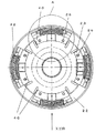
【発明の実施の形態】
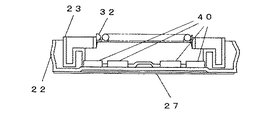
図1はこの発明のダンパー付ロックアップピストンの第1実施例の正面図、図2は図1の円A内の部分のX方向矢視図であって、22はコアプレート、23はリテーナプレートを示し、リテーナプレートは加締部26においてコアプレートに固着されている。27はコアプレート22に貼着されている。クラッチ摩擦材、32はスプリング、40はコアプレートに設けられた凸部である。
【0006】
凸部40はコアプレートにプレス加工によって形成されている。この実施例では凸部40はリテーナプレート23の周方向両端部外側にリテーナプレートの径方向の片に沿った形状に形成されている。
【0007】
このようにリテーナプレート23の周方向両端部外側に凸部40を形成したので、剪断力が従来より向上し、またリテーナプレートの小型化に対して設計の自由度を増大させることができる。
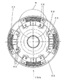
【0008】
図3は第2実施例の正面図、図4は図3の円Bの部分のY方向矢視図であって、図1、図2と同じ符号は同じ部分を表している。この第2実施例においては、凸部40はリテーナプレート23の周方向両端部外側と、内径側部内側とに、それぞれの形状に沿った形状で設けられている。
【0009】
このような凸部の配置にしておくと、万一加締部に大きな力が加わってもリテーナプレートの保持性が良い。
【0010】
図5は第3実施例の正面図、図6は図5の円Cの部分のZ方向矢視図であって、やはり図1以下の図面と同じ符号は同じ部分を表している。この実施例においては、凸部40の位置は図3、図4の第2実施例と同じであるが、凸部40の形状を円柱形としている。凸部をこのような形状にすれば加工性が良い。
【0011】
【効果】
この発明は前記の如き構成であって、小型であっても耐剪断力が向上したダンパー付ロックアップピストンを得ることができた。
【図面の簡単な説明】
【図1】 第1実施例の正面図
【図2】 図1の円Aの部分のX方向矢視図
【図3】 第2実施例の正面図
【図4】 図3の円Bの部分のY方向矢視図
【図5】 第3実施例の正面図
【図6】 図5の円Cの部分のZ方向矢視図
【図7】 ロックアップクラッチを有するトルクコンバータの構成を示す断面図
【図8】 従来のロックアップピストンの正面図
【符号の説明】
1 エンジン出力軸の取付部
2 ポンプ
3 タービン
4 ステータ
5 タービンハブ
6 中心軸線
10 トルクコンバータ本体
21 入力ケース
22 コアプレート
23 リテーナプレート
24 切り起こし
25 スプリング端面支承部材
26 加締部
27 クラッチ摩擦材
28 フランジ
32 スプリング
40 凸部[0001]
[Industrial application fields]
The present invention relates to a lockup piston with a damper of a lockup clutch of a torque converter.
[0002]
[Prior art]
In order to facilitate understanding of the present invention, FIG. 7 shows a basic configuration of a torque converter with a lock-up, and FIG. 8 shows a conventional lock-up piston taken out. Mounting portion with the output shaft, 2 is a pump, 3 is a turbine, 4 is a stator, 5 is a turbine hub, 6 is a central axis, 21 is an input case, 22 is a core plate, 23 is a
Since the torque converter technology is well known and will not be described in detail, slippage is unavoidable between the fluid couplings when the rotational speeds of the input shaft and the output shaft are equal.
Therefore, a lock-up clutch is provided, and in the drawing, if pressure is applied to the right side of the
[0003]
[Problems to be solved by the invention]
As described above, the conventional lockup piston with a damper has a retainer plate holding a spring attached thereto by caulking. However, automatic transmissions to which torque converters are attached are becoming smaller and lighter. To cope with this, the torque converter device is also being developed to be smaller and lighter. However, if the retainer plate holding the spring of the lock-up clutch is made smaller, the crimping range becomes narrower, and the core plate and retainer plate The force for fastening is lower than the conventional level. The fastening force is a shearing force with the mating member and a peeling force for holding the retainer plate on the core plate, but the lack of the internal shearing force becomes a problem. That is, if the shearing force is insufficient, there is a possibility that a sufficient function for torque transmission may not be exhibited.
[0004]
[Means for Solving the Problems]
In the present invention, in order to eliminate the above-mentioned drawbacks, a lock-up piston with a damper is obtained in which convex portions are provided on both sides in the circumferential direction of the retainer plate fixed to the core plate so as to receive a shearing force at the convex portions. .
[0005]
DETAILED DESCRIPTION OF THE INVENTION
1 is a front view of a first embodiment of a lock-up piston with a damper according to the present invention, FIG. 2 is a view taken in the direction of the arrow X in a circle A in FIG. 1, 22 is a core plate, and 23 is a retainer plate The retainer plate is fixed to the core plate at the
[0006]
The
[0007]
Thus, since the
[0008]
FIG. 3 is a front view of the second embodiment, and FIG. 4 is a view in the Y direction of the circle B in FIG. 3. The same reference numerals as those in FIGS. 1 and 2 represent the same parts. In this 2nd Example, the
[0009]
If such a convex portion is arranged, the retainer plate can be retained even if a large force is applied to the crimped portion.
[0010]
FIG. 5 is a front view of the third embodiment, and FIG. 6 is a view in the Z direction of a portion of a circle C in FIG. 5, and the same reference numerals as those in FIG. In this embodiment, the position of the
[0011]
【effect】
The present invention has the configuration as described above, and can obtain a lock-up piston with a damper having improved shear resistance even if it is small.
[Brief description of the drawings]
FIG. 1 is a front view of the first embodiment. FIG. 2 is a view taken in the direction of the arrow X in the circle A of FIG. 1. FIG. 3 is a front view of the second embodiment. Fig. 5 is a front view of the third embodiment. Fig. 6 is a Z direction view of a circle C portion in Fig. 5. Fig. 7 is a cross-sectional view showing a configuration of a torque converter having a lockup clutch. [Fig. 8] Front view of conventional lock-up piston [Explanation of symbols]
DESCRIPTION OF SYMBOLS 1 Engine output
Claims (3)
前記円盤型コアプレートのリテーナ周方向両側に凸部を設け、凸部で剪断力を受けるようにしたことを特徴とするダンパー付ロックアップピストン。A lock-up piston used for a torque converter having a lock-up clutch, and a damper lock with a friction material fixed to one side of a disk-shaped core plate having an outer peripheral flange and a retainer plate holding a spring on the opposite side In the up piston,
A lock-up piston with a damper, wherein convex portions are provided on both sides of the retainer circumferential direction of the disc-shaped core plate so as to receive a shearing force at the convex portions .
前記円盤型コアプレートのリテーナプレート周方向両側と内径側に凸部を設け、凸部で剪断力を受けるようにしたことを特徴とするダンパー付ロックアップピストン。A lock-up piston used for a torque converter having a lock-up clutch, and a damper lock with a friction material fixed to one side of a disk-shaped core plate having an outer peripheral flange and a retainer plate holding a spring on the opposite side In the up piston,
A lockup piston with a damper, characterized in that convex portions are provided on both sides of the retainer plate in the circumferential direction and the inner diameter side of the disc-shaped core plate so as to receive a shearing force at the convex portions .
Priority Applications (2)
| Application Number | Priority Date | Filing Date | Title |
|---|---|---|---|
| JP19494098A JP4093383B2 (en) | 1998-06-05 | 1998-06-05 | Lock-up piston with damper |
| US09/326,711 US6109406A (en) | 1998-06-05 | 1999-06-07 | Lockup piston with a damper |
Applications Claiming Priority (1)
| Application Number | Priority Date | Filing Date | Title |
|---|---|---|---|
| JP19494098A JP4093383B2 (en) | 1998-06-05 | 1998-06-05 | Lock-up piston with damper |
Publications (2)
| Publication Number | Publication Date |
|---|---|
| JPH11351354A JPH11351354A (en) | 1999-12-24 |
| JP4093383B2 true JP4093383B2 (en) | 2008-06-04 |
Family
ID=16332874
Family Applications (1)
| Application Number | Title | Priority Date | Filing Date |
|---|---|---|---|
| JP19494098A Expired - Fee Related JP4093383B2 (en) | 1998-06-05 | 1998-06-05 | Lock-up piston with damper |
Country Status (2)
| Country | Link |
|---|---|
| US (1) | US6109406A (en) |
| JP (1) | JP4093383B2 (en) |
Families Citing this family (4)
| Publication number | Priority date | Publication date | Assignee | Title |
|---|---|---|---|---|
| JP2005282688A (en) * | 2004-03-29 | 2005-10-13 | Mazda Motor Corp | Fluid gearing with lock-up clutch |
| DE102007018654B4 (en) * | 2007-04-20 | 2018-05-17 | Zf Friedrichshafen Ag | torsional vibration damper |
| CN117202872A (en) | 2021-01-17 | 2023-12-08 | 印斯拜尔Md有限公司 | Shunt with blood flow indicator |
| EP4313255A4 (en) | 2021-03-25 | 2024-07-10 | Inspire M D Ltd | Device for shunting blood between the arterial and venous systems |
Family Cites Families (3)
| Publication number | Priority date | Publication date | Assignee | Title |
|---|---|---|---|---|
| US4702721A (en) * | 1986-03-18 | 1987-10-27 | Borg-Warner Automotive, Inc. | Long travel damper with low lag dynamic spring retainers |
| FR2738890B1 (en) * | 1995-09-19 | 1997-10-24 | Valeo | TORSION SHOCK ABSORBER FOR LOCKING CLUTCH AND LOCKING CLUTCH COMPRISING SUCH A TORSION SHOCK ABSORBER |
| JP2816958B2 (en) * | 1995-10-27 | 1998-10-27 | 株式会社エフ・シー・シー | Torque damper |
-
1998
- 1998-06-05 JP JP19494098A patent/JP4093383B2/en not_active Expired - Fee Related
-
1999
- 1999-06-07 US US09/326,711 patent/US6109406A/en not_active Expired - Lifetime
Also Published As
| Publication number | Publication date |
|---|---|
| JPH11351354A (en) | 1999-12-24 |
| US6109406A (en) | 2000-08-29 |
Similar Documents
| Publication | Publication Date | Title |
|---|---|---|
| EP0717211B1 (en) | Flexible plate for transmitting torque | |
| JP2003507661A (en) | One-way clutch and manufacturing method thereof | |
| JP2001514366A (en) | Fluid type torque converter | |
| US5826688A (en) | Torsion damper for a locking clutch and a locking clutch including such a torsion damper | |
| US20030029685A1 (en) | Hydrodnamic clutch device | |
| JP2010255753A (en) | Power transmission device | |
| WO1988003621A1 (en) | Lockup damper for torque converters | |
| JP3621813B2 (en) | Torque converter | |
| JP2009531608A (en) | One-way clutch with integrated stator | |
| JP2003505652A (en) | Automotive fluid power coupling device | |
| JP3520502B2 (en) | How to assemble a coaxial cover, substrate and ring | |
| JPH0624604Y2 (en) | Lockup damper for torque converter | |
| JP4093383B2 (en) | Lock-up piston with damper | |
| EP0570036A2 (en) | Torque converter and clutch assembly | |
| US5105921A (en) | Damper disk | |
| EP0660012B1 (en) | A fluid coupling with a lock-up clutch | |
| US5904231A (en) | Fluid coupling apparatus, especially for a motor vehicle transmission | |
| US4852711A (en) | Clutch disc | |
| JP3165666B2 (en) | Torque converter | |
| JP5213863B2 (en) | Combined body of first cylindrical member and second cylindrical member | |
| US6237221B1 (en) | Method of fixing impeller blades of a torque converter | |
| WO2018191095A1 (en) | Torque converter | |
| EP0769639A2 (en) | A torque converter with a lock-up mechanism | |
| JPS62228752A (en) | Vibrating damper assembly | |
| JP2547748Y2 (en) | Seal structure of pressure receiving member |
Legal Events
| Date | Code | Title | Description |
|---|---|---|---|
| A521 | Request for written amendment filed |
Free format text: JAPANESE INTERMEDIATE CODE: A523 Effective date: 20050412 |
|
| A621 | Written request for application examination |
Free format text: JAPANESE INTERMEDIATE CODE: A621 Effective date: 20050412 |
|
| A131 | Notification of reasons for refusal |
Free format text: JAPANESE INTERMEDIATE CODE: A131 Effective date: 20070725 |
|
| A521 | Request for written amendment filed |
Free format text: JAPANESE INTERMEDIATE CODE: A523 Effective date: 20070905 |
|
| TRDD | Decision of grant or rejection written | ||
| A01 | Written decision to grant a patent or to grant a registration (utility model) |
Free format text: JAPANESE INTERMEDIATE CODE: A01 Effective date: 20080227 |
|
| A61 | First payment of annual fees (during grant procedure) |
Free format text: JAPANESE INTERMEDIATE CODE: A61 Effective date: 20080228 |
|
| FPAY | Renewal fee payment (event date is renewal date of database) |
Free format text: PAYMENT UNTIL: 20110314 Year of fee payment: 3 |
|
| R150 | Certificate of patent or registration of utility model |
Free format text: JAPANESE INTERMEDIATE CODE: R150 |
|
| FPAY | Renewal fee payment (event date is renewal date of database) |
Free format text: PAYMENT UNTIL: 20110314 Year of fee payment: 3 |
|
| FPAY | Renewal fee payment (event date is renewal date of database) |
Free format text: PAYMENT UNTIL: 20120314 Year of fee payment: 4 |
|
| FPAY | Renewal fee payment (event date is renewal date of database) |
Free format text: PAYMENT UNTIL: 20120314 Year of fee payment: 4 |
|
| FPAY | Renewal fee payment (event date is renewal date of database) |
Free format text: PAYMENT UNTIL: 20130314 Year of fee payment: 5 |
|
| FPAY | Renewal fee payment (event date is renewal date of database) |
Free format text: PAYMENT UNTIL: 20130314 Year of fee payment: 5 |
|
| FPAY | Renewal fee payment (event date is renewal date of database) |
Free format text: PAYMENT UNTIL: 20140314 Year of fee payment: 6 |
|
| R250 | Receipt of annual fees |
Free format text: JAPANESE INTERMEDIATE CODE: R250 |
|
| R250 | Receipt of annual fees |
Free format text: JAPANESE INTERMEDIATE CODE: R250 |
|
| R250 | Receipt of annual fees |
Free format text: JAPANESE INTERMEDIATE CODE: R250 |
|
| LAPS | Cancellation because of no payment of annual fees |