JP2009531608A - One-way clutch with integrated stator - Google Patents
One-way clutch with integrated stator Download PDFInfo
- Publication number
- JP2009531608A JP2009531608A JP2009501835A JP2009501835A JP2009531608A JP 2009531608 A JP2009531608 A JP 2009531608A JP 2009501835 A JP2009501835 A JP 2009501835A JP 2009501835 A JP2009501835 A JP 2009501835A JP 2009531608 A JP2009531608 A JP 2009531608A
- Authority
- JP
- Japan
- Prior art keywords
- disc
- component unit
- stator
- ring
- clutch
- Prior art date
- Legal status (The legal status is an assumption and is not a legal conclusion. Google has not performed a legal analysis and makes no representation as to the accuracy of the status listed.)
- Pending
Links
Images


Classifications
-
- F—MECHANICAL ENGINEERING; LIGHTING; HEATING; WEAPONS; BLASTING
- F16—ENGINEERING ELEMENTS AND UNITS; GENERAL MEASURES FOR PRODUCING AND MAINTAINING EFFECTIVE FUNCTIONING OF MACHINES OR INSTALLATIONS; THERMAL INSULATION IN GENERAL
- F16H—GEARING
- F16H41/00—Rotary fluid gearing of the hydrokinetic type
- F16H41/24—Details
- F16H41/28—Details with respect to manufacture, e.g. blade attachment
-
- F—MECHANICAL ENGINEERING; LIGHTING; HEATING; WEAPONS; BLASTING
- F16—ENGINEERING ELEMENTS AND UNITS; GENERAL MEASURES FOR PRODUCING AND MAINTAINING EFFECTIVE FUNCTIONING OF MACHINES OR INSTALLATIONS; THERMAL INSULATION IN GENERAL
- F16H—GEARING
- F16H41/00—Rotary fluid gearing of the hydrokinetic type
- F16H41/24—Details
- F16H41/26—Shape of runner blades or channels with respect to function
-
- F—MECHANICAL ENGINEERING; LIGHTING; HEATING; WEAPONS; BLASTING
- F16—ENGINEERING ELEMENTS AND UNITS; GENERAL MEASURES FOR PRODUCING AND MAINTAINING EFFECTIVE FUNCTIONING OF MACHINES OR INSTALLATIONS; THERMAL INSULATION IN GENERAL
- F16H—GEARING
- F16H41/00—Rotary fluid gearing of the hydrokinetic type
- F16H41/24—Details
- F16H2041/246—Details relating to one way clutch of the stator
-
- F—MECHANICAL ENGINEERING; LIGHTING; HEATING; WEAPONS; BLASTING
- F16—ENGINEERING ELEMENTS AND UNITS; GENERAL MEASURES FOR PRODUCING AND MAINTAINING EFFECTIVE FUNCTIONING OF MACHINES OR INSTALLATIONS; THERMAL INSULATION IN GENERAL
- F16H—GEARING
- F16H41/00—Rotary fluid gearing of the hydrokinetic type
- F16H41/24—Details
- F16H41/28—Details with respect to manufacture, e.g. blade attachment
- F16H2041/285—Details with respect to manufacture, e.g. blade attachment of stator blades
-
- F—MECHANICAL ENGINEERING; LIGHTING; HEATING; WEAPONS; BLASTING
- F16—ENGINEERING ELEMENTS AND UNITS; GENERAL MEASURES FOR PRODUCING AND MAINTAINING EFFECTIVE FUNCTIONING OF MACHINES OR INSTALLATIONS; THERMAL INSULATION IN GENERAL
- F16H—GEARING
- F16H45/00—Combinations of fluid gearings for conveying rotary motion with couplings or clutches
- F16H45/02—Combinations of fluid gearings for conveying rotary motion with couplings or clutches with mechanical clutches for bridging a fluid gearing of the hydrokinetic type
- F16H2045/0273—Combinations of fluid gearings for conveying rotary motion with couplings or clutches with mechanical clutches for bridging a fluid gearing of the hydrokinetic type characterised by the type of the friction surface of the lock-up clutch
- F16H2045/0278—Combinations of fluid gearings for conveying rotary motion with couplings or clutches with mechanical clutches for bridging a fluid gearing of the hydrokinetic type characterised by the type of the friction surface of the lock-up clutch comprising only two co-acting friction surfaces
-
- F—MECHANICAL ENGINEERING; LIGHTING; HEATING; WEAPONS; BLASTING
- F16—ENGINEERING ELEMENTS AND UNITS; GENERAL MEASURES FOR PRODUCING AND MAINTAINING EFFECTIVE FUNCTIONING OF MACHINES OR INSTALLATIONS; THERMAL INSULATION IN GENERAL
- F16H—GEARING
- F16H45/00—Combinations of fluid gearings for conveying rotary motion with couplings or clutches
- F16H45/02—Combinations of fluid gearings for conveying rotary motion with couplings or clutches with mechanical clutches for bridging a fluid gearing of the hydrokinetic type
Abstract
本発明は一般的にステータとクラッチとを有するトルクコンバータのための構成ユニットに関する。構成ユニットはステータのための第1の半部と第2の半部とを有し、該半部がそれぞれ1つの第1と第2との個別部分から構成されている。ステータの羽根は第1と第2の半部のための適当なリングの内部に配置されている。構成ユニットは一方向クラッチも含有している。第1と第2の半部は内側の周方向部分を有し、該周方向部分は該周方向部分がクラッチの1部を形成するように形成されている。構成ユニットは軸方向で移動可能な円板を有し、該円板はボスと結合されている。円板と周方向部分とは機能的に円板と周方向部分とがクラッチの1部を形成するように配置されている。若干の構想によれば円板と周方向部分とが互いに係合するように円板と周方向部分とが配置され、構成ユニットが円板を周方向部分に対して押すように配置された押動かしエレメントを有している。若干の構想では円板とボスは唯一の部分から形成されるか又は円板は軸方向でボスに対し移動させられることができる。 The present invention relates generally to a component unit for a torque converter having a stator and a clutch. The component unit has a first half and a second half for the stator, each half comprising one first and second individual part. The stator vanes are located inside suitable rings for the first and second halves. The component unit also contains a one-way clutch. The first and second halves have an inner circumferential portion that is formed such that the circumferential portion forms part of the clutch. The component unit has a disc movable in the axial direction, which is connected to a boss. The disc and the circumferential portion are functionally arranged so that the disc and the circumferential portion form part of the clutch. According to some concepts, the disc and the circumferential portion are arranged so that the disc and the circumferential portion are engaged with each other, and the component unit is arranged to push the disc against the circumferential portion. It has a moving element. In some concepts, the disc and boss can be formed from a single part or the disc can be moved relative to the boss in the axial direction.
Description
本発明は回転駆動する駆動ユニット(例えばモータ車両のモータ)と回転駆動されるユニット(例えばモータ車両における自動伝動装置)との間で力を伝達するための装置の改良に関する。特に本発明はステータと一方向クラッチとを合体させたトルクコンバータのための構成ユニットに関する。特に構成ユニットはステータとクラッチとによって共通に使用される部分又はコンポーネントを有している。 The present invention relates to an improvement in a device for transmitting a force between a drive unit (for example, a motor of a motor vehicle) that is rotationally driven and a unit (for example, an automatic transmission device in a motor vehicle) that is rotationally driven. In particular, the present invention relates to a structural unit for a torque converter in which a stator and a one-way clutch are combined. In particular, the component unit has parts or components commonly used by the stator and the clutch.
発明の背景
トルクコンバータのための、軸方向で接続及び遮断可能な一方向クラッチメカニズムは本出願人に譲渡されたUS特許出願NO.60/710828号、タイトル" Stator Having an Axially Engaging and Disengaging One-Way Clutch Mechanism for a Torque Converter "Brees et al により24.August 2005に出願の明細書に開示されており、ここでも背景技術として取上げられている。上記特許出願に開示されている装置は部分又はコンポーネントがステータとクラッチとによって共通して利用されると改善され得るものと想われる。このような共通する利用でトルクコンバータの部分の数、複素性及び費用は低減される。
BACKGROUND OF THE INVENTION An axially connectable and disengageable one-way clutch mechanism for a torque converter is described in US patent application no. No. 60/710828, entitled “Stator Having an Axially Engaging and Disengaging One-Way Clutch Mechanism for a Torque Converter” ing. It is believed that the device disclosed in the above patent application can be improved if parts or components are utilized in common by the stator and the clutch. Such common use reduces the number, complexity and cost of torque converter parts.
したがって長くから、ステータと一方向クラッチとのためのコンポーネントをトルクコンバータにおいて共通に利用し、ステータと一方向クラッチとの部品数、複素性及び費用を減少させることが望まれている。 Therefore, for a long time, it is desirable to commonly use components for the stator and the one-way clutch in the torque converter to reduce the number of parts, complexity and cost of the stator and the one-way clutch.
本発明の概要
本発明は総合的に、ステータとクラッチとから成るトルクコンバータのための構成ユニットであってステータのための第1の半部とステータのための第2の半部とを有する構成ユニットを対象としている。第1と第2の半部はそれぞれ単一の第1の部体と単一の第2の部材とから成り、第1と第2の半部の対応するリングの間にはステータの羽根が配置されている。構成ユニットは一方向クラッチを有し、第1と第2の半部は第1もしくは第2の内側の周方向部分を有し、この周方向部分は一方向クラッチの1部を形成するように機能的に配置されている。若干の構想では円板と第1の内側の周方向部分とは互いに係合するように配置されている。
SUMMARY OF THE INVENTION The present invention is generally a component unit for a torque converter comprised of a stator and a clutch, the component having a first half for the stator and a second half for the stator. Intended for units. The first and second halves each consist of a single first part and a single second member, with stator blades between the corresponding rings of the first and second halves. Is arranged. The component unit has a one-way clutch, the first and second halves have a first or second inner circumferential part, which circumferential part forms part of the one-way clutch Functionally arranged. In some concepts, the disc and the first inner circumferential portion are arranged to engage each other.
若干の構想によれば第1の内側の周方向部分は少なくとも1つの突起を有し、該突起は軸方向で少なくとも1つの第1の開口に配向されている。若干の構想によれば、円板は少なくとも1つの第2の開口を有し、第1の内側の周方向部分が少なくとも1つの第2の突起を有し、該第2の突起が軸方向で少なくとも1つの第2の開口に配向されている。 According to some concepts, the first inner circumferential portion has at least one protrusion, the protrusion being oriented in the axial direction to at least one first opening. According to some concepts, the disc has at least one second opening, the first inner circumferential portion has at least one second protrusion, and the second protrusion is axial. Oriented to at least one second opening.
若干の構想によれば構成ユニットは押動かしエレメントを有し、この押動かしエレメントは円板を軸方向で第1の内側の周方向部分に押付けるように配置されている。若干の構想によれば円板とボスは第3の個別部体から成り、押動かしエレメントは第2の内側の周方向部分と円板との間に配置されている。若干の構想によれば円板が軸方向でボスに対し移動させられることができ、押動かしエレメントは円板とボスとの間に配置されている。 According to some concepts, the component unit has a pushing element, which is arranged to push the disc axially against the first inner circumferential part. According to some concepts, the disc and the boss are composed of a third individual part, and the pushing element is arranged between the second inner circumferential portion and the disc. According to some concepts, the disc can be moved relative to the boss in the axial direction, and the push element is arranged between the disc and the boss.
若干の構想によれば構成ユニットはボスと第1のエレメントとの間に配置された押動かしエレメントを有し、このために第1又は第2の周方向部分が選ばれている。若干の構想によれば第1の半部はクラッチと第1の半部のリングとの間に配置された第1のリング形の部分を有し、第2の半部はクラッチと第2の半部との間に配置された第2のリング形の部分を有し、第1と第2のリング形の部分の少なくとも部分が接触している。さらにトルクコンバータは第1と第2の軸受とを有し、第1と第2のリング形の部分は機能的に、第1と第2のリング形の部分とが第1もしくは第2の軸受を受容するように配置されている。若干の構想によれば、第1と第2の半部は第1と第2のロックエレメントを有し、第1と第2のロックエレメントはそれらが第1もしくは第2の軸受と結合されているように機能的に配置されている。 According to some concepts, the component unit has a push element arranged between the boss and the first element, for which the first or second circumferential part is selected. According to some concepts, the first half includes a first ring-shaped portion disposed between the clutch and the first half ring, and the second half includes the clutch and the second half. A second ring-shaped portion disposed between the halves and at least portions of the first and second ring-shaped portions are in contact. The torque converter further includes first and second bearings, the first and second ring-shaped portions being functional and the first and second ring-shaped portions being the first or second bearing. Arranged to accept. According to some concepts, the first and second halves have first and second locking elements, which are coupled to the first or second bearing. Is functionally arranged.
全般的には本発明はトルクコンバータのためのステータとクラッチとを有する構成ユニットであって、ステータの第1の軸方向の部分とステータの第2の軸方向の部分と一方向クラッチとを有する構成ユニットも含んでいる。第1の軸方向の部分は半径方向でクラッチの外側に配置された第1のリング形の部分を有し、第2の軸方向の部分は半径方向でクラッチの外側に配置された第2のリング形の部分を有している。この場合、第1と第2のリング形の部分の少なくとも部分は接触し、第1と第2のリング形の部分はこれらが第1もしくは第2の軸受を受容するように機能的に配置されている。 In general, the present invention is a structural unit having a stator and a clutch for a torque converter, comprising a first axial portion of the stator, a second axial portion of the stator, and a one-way clutch. It also includes a configuration unit. The first axial portion has a first ring-shaped portion disposed radially outside the clutch, and the second axial portion is a second radially disposed outside the clutch. It has a ring-shaped part. In this case, at least parts of the first and second ring-shaped parts are in contact, and the first and second ring-shaped parts are functionally arranged such that they receive the first or second bearing. ing.
さらに本発明は全般的に、トルクコンバータのためのステータとクラッチとを有する構成ユニットであって、ステータのための第1の軸方向の端部を有し、第1の軸方向の端部がステータの羽根とステータの軸との間に配置された第1の周方向部分を有し、構成ユニットがステータのための第2の軸方向の端部を有し、この第2の軸方向の端部が羽根と軸との間に配置された第2の周方向部分を有し、軸方向で移動可能な円板を有する一方向クラッチを有している構成ユニットを含んでいる。第1と第2の端部はそれぞれ1つの第1と第2の個別の部体から形成され、円板と第1の周方向部分とはこれらが一方向クラッチの1部を形成するように機能的に配置され、円板と第1の周方向部分とはこれらが互いに内外に係合するように配置されている。 Furthermore, the present invention generally is a component unit having a stator and a clutch for a torque converter, the first unit having a first axial end for the stator, the first axial end being A first circumferential portion disposed between the stator blades and the stator shaft, the component unit having a second axial end for the stator, the second axial portion It includes a component unit having a one-way clutch having a second circumferential portion disposed between the vane and the shaft and having a disc movable in the axial direction. The first and second ends are each formed from one first and second separate body, so that the disc and the first circumferential portion form part of a one-way clutch. Arranged functionally, the disc and the first circumferential portion are arranged so that they engage each other inward and outward.
本発明の全般的な課題は2つの軸方向のセグメント又は半部から形成されたステータを提供することである。 The general problem of the present invention is to provide a stator formed from two axial segments or halves.
本発明の別の課題はトルクコンバータにおいてステータと一方向クラッチとの部品数と複素性とを減じることである。 Another object of the present invention is to reduce the number of components and complexity of the stator and the one-way clutch in the torque converter.
本発明のさらに別の課題はトルクコンバータのためにより簡単に取付けられ得るステータと一方向クラッチを提供することである。 Yet another object of the present invention is to provide a stator and one-way clutch that can be more easily mounted for a torque converter.
本発明のさらなる課題は費用的に好適な製作方法を使用して製作されるステータと一方向クラッチとを提供することである。 It is a further object of the present invention to provide a stator and a one-way clutch that are manufactured using a cost-effective manufacturing method.
本発明のさらなる課題と利点は本発明の有利な実施例についての以下の説明、添付図面及び従属請求項に開示されている。 Further objects and advantages of the invention are disclosed in the following description of advantageous embodiments of the invention, the accompanying drawings and the dependent claims.
発明の詳細な説明
最初に異なる図面において同じ符号が本発明の同じ又は機能的に似た構造エレメントを示していることを明らかにしておく。本発明は現時点で有利であると見なした構想に関して記述したにも拘らず、本発明が記載した構想に限定されないことは明白である。
DETAILED DESCRIPTION OF THE INVENTION It will first be made clear that the same reference numerals in different drawings designate the same or functionally similar structural elements of the present invention. Although the invention has been described in terms of concepts that are currently considered advantageous, it is clear that the invention is not limited to the concepts described.
さらに本発明は記述した所定の方法、材料及び変更に限定されず、もちろん、その限りにおいて変化させることができることは当然である。さらにここで使用した名称は所定の構想を説明するためだけのものであって、従属請求項によって制限された本発明の権利範囲の制限と理解されるべきではないことは明白である。 Furthermore, the invention is not limited to the specific methods, materials and modifications described but of course can be varied in so far. Furthermore, it is clear that the names used here are only for the purpose of describing a given concept and should not be understood as a limitation on the scope of the invention, which is limited by the dependent claims.
特別な記載がない限り、ここで使用されているすべての技術的及び学問的な概念は、この発明に属する分野の専門家にとって一般的な意味と同じ意味を持つものである。本発明を構成するため又はテストするためにはここで記述したものと類似した又は同等価値を有する任意の方法、装置又は材料を使用できるにも拘らず、以下の記述は有利な方法、装置及び材料について記載する。 Unless defined otherwise, all technical and academic concepts used herein have the same meaning as commonly used by those skilled in the art to which this invention belongs. Although any method, apparatus or material similar or equivalent in value to that described herein can be used to configure or test the present invention, the following description is an advantageous method, apparatus and The material is described.
図1においてはトルクコンバータ102における、本発明による、ステータとクラッチとを有する構成ユニット100の部分断面図が示されている。この場合には軸方向に移動可能なクラッチ円板とボスは係合させられていない。
FIG. 1 shows a partial cross-sectional view of a
図2には係合した状態で構成ユニット100の部分横断面が示されている。以下の記述は図1と図2とに関するものである。構成ユニット100はステータ106の第1の半部104と第2の半部108とを有している。半部とはステータの構造がほぼ半部104と108とによって形成されていると解されるべきである。半部104と108は軸方向の半部又は軸方向の端部と称することができる。換言すれば半部104と108は軸109に対し半径方向の平面に沿って互いに結合されている。第1と第2の半部はそれぞれ1つの部体から成っている。図示の横断面では例えば半部104は唯一の部体から成り、端部110から端部112まで達している。若干の構想ではステータ106は打抜きで形成されている。例えば半部104と108はそれぞれ打抜かれた材料から成っている。
FIG. 2 shows a partial cross section of the
ステータ106の羽根は技術的に公知である任意の手段で形成されることができる。若干の(図示されていない)構想によれば一体の羽根が使用される。2部分から成る羽根は例えば本願出願人に譲渡されたUS特許(タイトル" Two-Part Stator Blade "Brees et al により本願と同時に出願)明細書の記載及び図に開示されている。ステータの羽根114と116は半部104もしくは108のリング118もしくは120の内部に配置されている。したがって上記半部又は軸方向の端部は少なくとも羽根と結合された構造に所属している。
The vanes of the
若干の構想によれば半部104もしくは108の内側の周方向部分122,124は、本出願人に譲渡されたUS特許出願(タイトル" Stator and One-Way Clutch Assembly for a Torque Converter "Hemphill et al により本願と同日に出願)に記載されているように配置されている。若干の構想によれば部分122,124は半部104もしくは108の統合された構成部分である。つまり、部分122と半部104とは単一の材料部体から形成されている。若干の構想(図示されておらず)によれば部分122と124は半部104もしくは108から離して形成され、任意の技術的に公知の手段で半部104もしくは108と結合されている。クラッチ126は軸方向で移動可能な円板128を有し、該円板128はボス130と結合されている。図1と2とにおいては円板128はボスと離して形成されており、回転方向でボスと連結しかつ軸方向でボスに対し移動させられることができる。例えば円板128のセグメント132は軸方向でボス130の開口134を通して突出する。セグメント132は開口の縁部にてボスと連結され、開口内へ移動させられる。円板128をボスと係合させるためには他の配置を使用し、円板を軸方向でボスに対し移動させることができることは明らかであろう。
According to some concepts, the inner
円板128と部分122又は124は機能的に、両者がクラッチ126の上記部分を形成するように配置される。例えば図1と図2とにおいては、部分122と124はクラッチの軸方向の端部である。さらに円板128と部分122又は124はそれらが互いに係合するように配置されている。図1と図2とにおいては円板128と部分124とがそれらが互いに係合するように配置されている。係合とは、円板128と部分122又は124とが、ステータが係合したモードで運転されるとき、つまり回転エネルギをステータからボス130に伝達しようとするときに、円板と部分との該当する部分とが合体しかつ係合するように配置されていることを意味する。
The
若干の構想によれば部分124は少なくとも1つの開口136を有し、円板128は少なくとも1つの突起138を有している。この突起138は開口136に軸方向で配向されている。軸方向の配向とは開口と突起とが軸109に対し平行に配向されていることを意味する。開口136と突起138を形成するためには技術的に公知の任意の手段を使用することができる。さらに若干の構想によれば本出願人に譲渡されたUS特許出願NO.60/710828号(タイトル" Stator Having an Axially Engaging and Disengaging One-Way Clutch Mechanism for a Torque Converter "Brees et al により、24.August 2005に出願)に記載されている鋸歯形の隆起部とスリットを使用することができる。若干の図示されていない構想によれば、部分124は開口の代わりに突起に配向された凹部を有している。つまり、クラッチにおける部分124は一貫している(開口を有していない)。突起は鋸歯形であり、凹部はほぼノッチの形を有していることができる。突起と凹部は、部分124が係合モードで回転すると、突起と凹部とが互いに正確に接触するように互いに補完しあう。若干の図示されていない構想によれば、上記の配置は逆になっている。つまり、円板128は少なくとも1つの開口を有し、部分124は少なくとも1つの、開口に配向された突起を有している。
According to some concepts,
構成ユニット100は押動かしユニットをも有し、該押動かしユニットは円板128を軸方向で、それぞれ連結するために設けられた部分122又は124に対して押す。図1と図2とにおいてはエレメント140はボス130と円板128との間に配置されかつ軸方向142で、つまり部分124の方向で力を発生させる。エレメント140としては技術的に公知である任意の押動かしエレメントを用いることができる。しかしこの押動かしエレメントにはダイヤフラムばね又は周方向でフィンガのように成形されたばね以外のものも含まれる。
The
若干の構想によれば構成ユニット100は部分124とボスとの間に配置された摩耗保護エレメント144を含んでいる。エレメント144としては技術的に公知である任意の摩耗保護エレメントを用いることができるが、これにはブッシュ以外のものも含まれる。若干の図示されていない構想によれば、部分124は直接的にボス130に接触している。一般的には部分124はボスに直接的に接触することを可能にするためにボスよりもやわらかい。若干の図示されていない構想によれば、円板128と部分122と124との配置は逆である。例えば部分122は円板128と連結するように配置されている。この場合には摩耗保護エレメントは部分122とボスとの間に配置されるか又は部分122は直接ボスに接触する。
According to some concepts,
若干の構想によれば、半部104と108はクラッチ126とリング118もしくは120との間に配置されたリング形の部分146もしくは148を含んでいる。部分146と148は少なくとも部分的に軸方向で接触しあう。つまり軸線109に平行な線に沿って接触しあう。例えば部分146の面150は部分148の面152に接触する。若干の構想によれば部分146と148は機能的に、それらがカプセル化されていない軸受154もしくはカプセル化されていない軸受156を受容するように配置されている。構成ユニットはカプセル化された又はカプセル化されていない軸受との組合わせに限定されない。又、軸受の代わりに技術的に公知である他の手段を用いることができることは明らかであるが、これは押圧円板とブッシュに限られるものではない。若干の構想によれば半部104,108は図示されていない確保エレメント、例えばU字形ばねを軸受を固定するために有している。部分146と148は互いに接触する硬い部分であるのでこれらの部分は軸受を保持しかつ軸受を正しい配置に保つために補強される必要はない。換言すれば負荷は直接部分146と148とを介して伝達される。
According to some concepts,
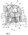
図3にはトルクコンバータ202における本発明によるステータとクラッチとを有する構成ユニット200であって、統合されたクラッチ円板とボスと統合された構成ユニット200が係合させていないモードで部分断面図で示されている。
FIG. 3 is a partial cross-sectional view of the
図4には係合させられたモードで構成ユニット200が部分断面図で示されている。以下の記述は図3と図4と関連して行なう。構成ユニット200はステータ206のための第1の半部204と第2の半部208とを含んでいる。一般的にはステータ106と半部104と108とに関する記述は構成ユニット200のためにも当て嵌まる。半部とはステータの構造がほぼ半部204と208とによって形成されていることを表している。半部204と208は軸方向の半部又は軸方向の端部として表すこともできる。換言すれば半部204と208は軸線209に関し半径方向の平面に沿って互いに結合されている。第1と第2の半部はそれぞれ個別の部体から形成されている。例えば図示の横断面では半部204は端部210から端部212まで達する唯一の部体から成っている。若干の構想ではステータ206は打抜きによって形成されている。例えば半部204と208は適当な打抜かれた金属部分から形成されている。
FIG. 4 shows the
ステータの羽根214と215は半部204と208のリング218もしくは220の内部に配置されている。図1と図2とに関する羽根114と116とについての記述は図3と図4とにも当て嵌まり、省略を目的として繰返さない。
Stator blades 214 and 215 are disposed within
若干の構想によれば半部204もしくは208の内側の周方向部分222と224は、本出願人に譲渡されたUS特許出願(タイトル" Stator and One-Way Clutch Assembly for a Torque Converter "Hemphill et al により本願と同日に出願)に記載されているように一方向クラッチ226の1部を形成するように配置されている。若干の構想によれば、部分222と224は半部204もしくは208の統合された構成部分である。つまり部分222と半部204は唯一の部体から形成されている。若干の図示されていない構想によれば、部分222と224とは半部204もしくは208から分離させられて形成され、技術的に公知の任意の手段で半部204もしくは208と結合されている。クラッチ226は軸方向で移動可能な円板228を有し、円板228はボス230と結合されている。図3と図4とにおいては円板228はボスと共通の部分を形成している。すなわち、円板228とボス230は唯一の材料部体から形成されている。図3と図4とに示された構想によればボス230は軸方向で移動させられることができる。以下、円板228とボス230の概念は交換可能に使用されている。
According to some concepts, the inner
円板228と部分222又は224は機能的にこれらがクラッチ226の上記部分を形成するように配置されている。例えば部分222と224は図3と図4とにおいてクラッチの軸方向の端部を形成している。さらに円板228と部分222と224とはそれらが互いに係合するように配置されている。図3と図4においては円板228と部分222とが互いに係合するように配置されている。係合とは、ステータが係合させられたモードで働かされると、つまり回転エネルギをステータからボス230へ伝達しようとすると、円板228と部分222又は224との適当な部分とが当接しかつ係合するように円板228と部分222又は224とが形成されていることである。さらに適当な前記部分はステータがフリー回転モードで働かされると、つまりステータとボスとが回転方向で互いに分離されていると、セグメントと円板とが例えば係合することなしに相対的に滑動することでセグメントと円板とが互いに無関係に回動するように配置されている。
The
若干の構想によれば円板228は少なくとも1つの開口236を有し、部分222は少なくとも1つの突起238とを有している。この突起238は軸方向で開口236に配向されている。開口236と突起238とを形成するためには技術的に公知の任意の手段を使用することができる。さらに若干の構想によれば、本願出願人に譲渡されたUS特許出願NO.60/710828号タイトル" Stator Having an Axially Engaging and Disengaging One-Way Clutch Mechanism for a Torque Converter "Brees et al により24.August 2005に出願に記載されているような鋸歯形の隆起部とスリットとを有する構成ユニットを使用することもできる。図1と図2とにおける円板128と部分124とのための突起と開口とに関する説明は円板228と部分222とにも当て嵌まる。
According to some concepts, the
若干の図示されていない構想によれば、上記配置は逆になっている。つまり、部分222が少なくとも1つの開口を有し、円板228が開口に半径方向で配向された少なくとも1つの突起を有している。
According to some not shown concepts, the arrangement is reversed. That is, the
構成ユニット200は押動かしエレメントをも有し、この押動かしエレメントは円板228を軸方向に、それぞれ連結のために設けられた部分222又は224を押す。図3と図4とにおいてはエレメント240が部分224と円板228との間に配置され、力を軸方向242で、つまり部分222の方向に発生させる。エレメント40としては技術的に公知の任意の押動かしエレメントを用いることができるが、これはダイヤフラムばね又は周方向にフィンガのように形成されたばねに限定されるものではない。
The
若干の構想によれば部分224とボスとの間に配置された摩耗保護エレメント244を含んでいる。エレメント244としては技術的に公知の任意の摩耗保護エレメントを用いることができるがこれはブッシュに限定されない。若干の図示されていない構想によれば、部分224は直接ボス230に接触している。通常はこの直接的な接触を可能にするために部分224はボスよりもやわらかい。若干の図示されていない構想によれば、円板228と部分222と224との配置は反対である。例えば部分224は円板228と連結されるように配置されている。この場合には摩耗保護エレメントが部分222とボスとの間に配置されるか又は部分222がボスに直接的に接することができる。
Some concepts include a
若干の構想によれば部分204と208はリング状の部分246もしくは248を有している。このリング状の部分246もしくは248は少なくとも部分的に軸方向で接触する。例えば部分246の面250は部分248の面252に接触する。若干の構想によれば部分246と248はそれらがカプセル化されていない軸受254もしくはカプセル化された軸受256を受容するように配置されている。構成ユニットはカプセル化された又はカプセル化されていない軸受との組合わせに限定されない。軸受の代わりに他の技術的な手段を使用することができることは明白であるが、押圧円板とブッシュに限られるものではない。若干の構想によれば半部204と208は軸受を固定するために図示されていない確保エレメント、例えばU字形ばねを有している。部分246と248は互いに接触する固体部分であるので、これらの部分は軸受を保持しかつ軸受を正しい位置に保つために補強される必要はない。換言すれば負荷は直接部分246と248とを介して伝達されることができる。
According to some concepts,
図1と図2とにおいては半部104と108は前記記述によればクラッチ126の1部を形成している。例えば部分124はステータとクラッチの1部、特にクラッチの係合するか又は連結するメカニズムの1部を形成する。部分122は他方の端部を形成する。つまり、クラッチ126は軸方向で少なくとも部分的に部分122と124との間に閉じ込められている。したがってステータ106とクラッチ126は一緒に製作されるか又は組立てられていることができるので、部品の数及び複素性が低減させられる。例えば構成エレメント100は完全に組立てられてトルクコンバータ102に挿入されることができる。さらに構成ユニット100は完成したユニットを形成する。つまり、クラッチ126のコンポーネントが部分122と124との間に配置されると部分はこのコンポーネントをその位置を保持し、構成ユニット100はユニットとして使用することができる。例えば構成ユニットを一個所で組立て、次いでトルクコンバータ内に組込むために他の個所へ搬送されることができる。構成ユニット100は図示の配置に限定されるものではないことは明らかである。例えば本願発明の精神と権利範囲とには、構成ユニットのコンポーネントの他の大きさ、形状、組合わせ、配置及び配向が含まれることができる。上記記述は図3と図4とにおける構成ユニット200とトルクコンバータ202とにも当て嵌まる。
In FIGS. 1 and 2,
したがって本発明の課題は専門家が本発明の変更を想定できるにも拘らず効果的に解決される。さらに上記記述は本発明を説明するためのものであり、本発明を限定するものではない。したがって本発明の精神と権利範囲を逸脱することなく、本発明の他の実施形態が可能である。 Therefore, the problem of the present invention can be effectively solved in spite of the fact that an expert can assume the modification of the present invention. Further, the above description is for explaining the present invention, and does not limit the present invention. Accordingly, other embodiments of the invention are possible without departing from the spirit and scope of the invention.
100 構成ユニット
102 トルクコンバータ
104 半部
106 ステータ
108 半部
109 軸
110 端部
112 端部
118 リング
120 リング
122 周方向部分
124 周方向部分
126 クラッチ
130 ボス
136 開口
138 突起
140 エレメント
144 エレメント
146 部分
148 部分
150 面
152 面
154 軸受
156 軸受
200 構成ユニット
202 トルクコンバータ
204 半部
206 ステータ
208 半部
209 軸線
210 端部
212 端部
214 羽根
215 羽根
218 リング
220 リング
222 周方向部分
224 周方向部分
226 クラッチ
228 円板
230 ボス
236 開口
238 突起
240 エレメント
244 摩擦保護エレメント
246 部分
248 部分
250 面
252 面
254 軸受
256 軸受
DESCRIPTION OF
Claims (17)
Applications Claiming Priority (2)
| Application Number | Priority Date | Filing Date | Title |
|---|---|---|---|
| US78569306P | 2006-03-24 | 2006-03-24 | |
| PCT/DE2007/000386 WO2007110023A1 (en) | 2006-03-24 | 2007-03-01 | One-way clutch with integrated stator |
Publications (2)
| Publication Number | Publication Date |
|---|---|
| JP2009531608A true JP2009531608A (en) | 2009-09-03 |
| JP2009531608A5 JP2009531608A5 (en) | 2011-05-06 |
Family
ID=38268844
Family Applications (1)
| Application Number | Title | Priority Date | Filing Date |
|---|---|---|---|
| JP2009501835A Pending JP2009531608A (en) | 2006-03-24 | 2007-03-01 | One-way clutch with integrated stator |
Country Status (6)
| Country | Link |
|---|---|
| US (1) | US20070220877A1 (en) |
| EP (1) | EP2002152A1 (en) |
| JP (1) | JP2009531608A (en) |
| CN (1) | CN101410655B (en) |
| DE (1) | DE112007000500A5 (en) |
| WO (1) | WO2007110023A1 (en) |
Families Citing this family (12)
| Publication number | Priority date | Publication date | Assignee | Title |
|---|---|---|---|---|
| DE102007025407A1 (en) | 2006-06-13 | 2007-12-20 | Luk Lamellen Und Kupplungsbau Beteiligungs Kg | Radial one-way clutch for a stator in a torque converter has an engagement element that is urged to engage the engagement and annular elements for connecting the two annular elements |
| JP5684515B2 (en) * | 2010-08-20 | 2015-03-11 | 株式会社エクセディ | Torque converter |
| JP5331768B2 (en) * | 2010-09-13 | 2013-10-30 | 日産自動車株式会社 | Torque converter |
| WO2012047665A2 (en) | 2010-09-27 | 2012-04-12 | Schaeffler Technologies Gmbh & Co. Kg | Stator centering plate |
| BR112013032708A2 (en) * | 2011-06-24 | 2017-01-24 | Honda Motor Co Ltd | torque converter stator structure |
| DE112013004575T5 (en) | 2012-09-19 | 2015-07-02 | Honda Motor Co., Ltd. | Stator arrangement for torque converter |
| US20140326566A1 (en) * | 2013-05-02 | 2014-11-06 | Schaeffler Technologies Gmbh & Co. Kg | One-way clutch with conical strut |
| JP5900541B2 (en) * | 2014-06-27 | 2016-04-06 | トヨタ自動車株式会社 | Torque converter with torsional vibration reduction device |
| JP6537104B2 (en) * | 2014-07-18 | 2019-07-03 | 株式会社エクセディ | Split molding integrated stator |
| US20170314661A1 (en) * | 2014-11-11 | 2017-11-02 | Schaeffler Technologies AG & Co. KG | Taper compensating hydrodynamic thrust bearings |
| JP6663759B2 (en) * | 2016-03-18 | 2020-03-13 | 株式会社エクセディ | Wheel stator assembly |
| CN112576724B (en) * | 2021-01-08 | 2022-03-18 | 吉林大学 | Hydraulic torque converter with adjustable ability holds with bionical gap |
Family Cites Families (21)
| Publication number | Priority date | Publication date | Assignee | Title |
|---|---|---|---|---|
| US710828A (en) | 1902-07-02 | 1902-10-07 | V H Blackington And Company | Badge. |
| US2034429A (en) * | 1932-10-08 | 1936-03-17 | Lavaud Dimitri Sensaud De | Hydraulic transmission |
| US2588668A (en) * | 1949-02-23 | 1952-03-11 | Chrysler Corp | Fluid coupling mounting |
| US3284881A (en) * | 1963-04-16 | 1966-11-15 | Stalker Corp | Bladed stators |
| US3385060A (en) * | 1966-05-02 | 1968-05-28 | Ford Motor Co | Hydrokinetic torque converter mechanism with multiple section reactor blades |
| US3572034A (en) * | 1969-11-21 | 1971-03-23 | Ford Motor Co | Fabricated two-piece stator assembly for hydrokinetic torque converters |
| US5070978A (en) * | 1990-04-19 | 1991-12-10 | Pires Paul B | One way drive device |
| US5597057A (en) * | 1993-10-26 | 1997-01-28 | Brenco, Inc. | One-way clutch apparatus |
| US5449057A (en) * | 1993-10-26 | 1995-09-12 | Frank; Arthur R. | One-way clutch apparatus |
| US5465575A (en) * | 1994-09-14 | 1995-11-14 | Nelson Metal Products Corporation | Torque converter and method for producing the same |
| JP3293463B2 (en) * | 1995-07-10 | 2002-06-17 | トヨタ自動車株式会社 | One-way clutch mechanism for torque converter |
| US5806643A (en) * | 1996-05-01 | 1998-09-15 | Epilogics, L.P. | One way drive device and mechanical assembly integrating the device |
| JPH09303529A (en) * | 1996-05-17 | 1997-11-25 | Toyota Motor Corp | One-way clutch mechanism of torque converter |
| US5853073A (en) * | 1996-09-03 | 1998-12-29 | Borg-Warner Automotive, Inc. | Ratchet one-way clutch assembly |
| US5829565A (en) * | 1996-12-20 | 1998-11-03 | Eaton Corporation | One-way clutch |
| US5918715A (en) * | 1997-06-09 | 1999-07-06 | Means Industries, Inc. | Overrunning planar clutch assembly |
| US6505721B1 (en) * | 2000-05-25 | 2003-01-14 | Means Industries, Inc. | Planar one-way clutch |
| JP4483036B2 (en) * | 2000-06-19 | 2010-06-16 | アイシン・エィ・ダブリュ株式会社 | Torque converter |
| US6571926B2 (en) * | 2001-02-12 | 2003-06-03 | Means Industries, Inc. | One-way clutch assembly featuring improved strut stability |
| JP2003028206A (en) * | 2001-07-17 | 2003-01-29 | Nsk Warner Kk | Ratchet one-way clutch, and stator using ratchet one- way clutch |
| CN2583203Y (en) * | 2002-12-04 | 2003-10-29 | 中国船舶重工集团公司第七一一研究所 | Hydraulic moment rariator blade row for pushdozer |
-
2007
- 2007-03-01 JP JP2009501835A patent/JP2009531608A/en active Pending
- 2007-03-01 DE DE112007000500T patent/DE112007000500A5/en not_active Withdrawn
- 2007-03-01 EP EP07711221A patent/EP2002152A1/en not_active Withdrawn
- 2007-03-01 WO PCT/DE2007/000386 patent/WO2007110023A1/en active Application Filing
- 2007-03-01 CN CN2007800105054A patent/CN101410655B/en not_active Expired - Fee Related
- 2007-03-23 US US11/726,881 patent/US20070220877A1/en not_active Abandoned
Also Published As
| Publication number | Publication date |
|---|---|
| CN101410655A (en) | 2009-04-15 |
| US20070220877A1 (en) | 2007-09-27 |
| CN101410655B (en) | 2010-09-29 |
| WO2007110023A1 (en) | 2007-10-04 |
| EP2002152A1 (en) | 2008-12-17 |
| DE112007000500A5 (en) | 2008-11-27 |
Similar Documents
| Publication | Publication Date | Title |
|---|---|---|
| JP2009531608A (en) | One-way clutch with integrated stator | |
| US7854306B2 (en) | Clutch assembly with an oil pump clutch housing and a carrier engaged with a clutch pack outer circumference | |
| US7849990B2 (en) | One-way clutch with dampening | |
| JP2008241044A (en) | Ratchet one-way clutch assembly | |
| WO2017127577A1 (en) | Torque converter drive assembly including bias spring and axially movable turbine | |
| US20090090593A1 (en) | Power Transmission Damper For a Torque Limiter | |
| JP4267703B2 (en) | Ratchet one-way clutch assembly | |
| JP2008157461A (en) | Axial one-way clutch with axial spacer | |
| US8776971B2 (en) | Stator and one-way clutch assembly for a torque converter | |
| WO2018155357A1 (en) | Torque converter | |
| US10451143B2 (en) | Damper device | |
| JP4684347B1 (en) | Damper device | |
| US9394982B2 (en) | Lock-up device for torque converter | |
| US6527094B2 (en) | Freewheel arrangement, in particular for a guide wheel of a hydrodynamic torque converter | |
| US20180180108A1 (en) | Segmented wedge clutch with stepped retaining spring | |
| US10808774B2 (en) | Clutch with selectable locked and one-way modes | |
| CN104514820A (en) | One-way mechanical clutch system and alternator comprising such a system | |
| CN104514819A (en) | One-way mechanical clutch system and alternator comprising such a system | |
| US20070193845A1 (en) | Clutch housing with wide lever spring retention slots and clutch housing with axially off-set tabs | |
| JP3601140B2 (en) | Damper device | |
| JP2006083997A (en) | Torque converter | |
| WO2017189458A1 (en) | Torque converter including damper assembly with hysteresis control package | |
| US10670083B2 (en) | Wedge clutch with wedge chain | |
| US6837347B2 (en) | Lockup device for fluid-type torque transmission device | |
| JP6660331B2 (en) | Torque converter |
Legal Events
| Date | Code | Title | Description |
|---|---|---|---|
| A521 | Written amendment |
Free format text: JAPANESE INTERMEDIATE CODE: A523 Effective date: 20100301 |
|
| A621 | Written request for application examination |
Free format text: JAPANESE INTERMEDIATE CODE: A621 Effective date: 20100301 |
|
| RD04 | Notification of resignation of power of attorney |
Free format text: JAPANESE INTERMEDIATE CODE: A7424 Effective date: 20101227 Free format text: JAPANESE INTERMEDIATE CODE: A7424 Effective date: 20101228 |
|
| A072 | Dismissal of procedure [no reply to invitation to correct request for examination] |
Free format text: JAPANESE INTERMEDIATE CODE: A073 Effective date: 20110713 |