JP4090712B2 - Underwater narrow part movement system - Google Patents
Underwater narrow part movement system Download PDFInfo
- Publication number
- JP4090712B2 JP4090712B2 JP2001231508A JP2001231508A JP4090712B2 JP 4090712 B2 JP4090712 B2 JP 4090712B2 JP 2001231508 A JP2001231508 A JP 2001231508A JP 2001231508 A JP2001231508 A JP 2001231508A JP 4090712 B2 JP4090712 B2 JP 4090712B2
- Authority
- JP
- Japan
- Prior art keywords
- movement
- moving device
- moving
- narrow part
- wheel
- Prior art date
- Legal status (The legal status is an assumption and is not a legal conclusion. Google has not performed a legal analysis and makes no representation as to the accuracy of the status listed.)
- Expired - Fee Related
Links
Images


Classifications
-
- Y—GENERAL TAGGING OF NEW TECHNOLOGICAL DEVELOPMENTS; GENERAL TAGGING OF CROSS-SECTIONAL TECHNOLOGIES SPANNING OVER SEVERAL SECTIONS OF THE IPC; TECHNICAL SUBJECTS COVERED BY FORMER USPC CROSS-REFERENCE ART COLLECTIONS [XRACs] AND DIGESTS
- Y02—TECHNOLOGIES OR APPLICATIONS FOR MITIGATION OR ADAPTATION AGAINST CLIMATE CHANGE
- Y02E—REDUCTION OF GREENHOUSE GAS [GHG] EMISSIONS, RELATED TO ENERGY GENERATION, TRANSMISSION OR DISTRIBUTION
- Y02E30/00—Energy generation of nuclear origin
- Y02E30/30—Nuclear fission reactors
Description
【0001】
【発明の属する技術分野】
本発明は、水が満たされた装置内の点検、検査、予防保全および補修を行うための装置に係り、とくに装置内外の狭隘な箇所へ各種の装置や治工具の搬送、位置決め、保持および移動を行うための装置に関する。
【0002】
【従来の技術】
例えば原子炉、とくに沸騰水型原子炉の炉内構造物は、高温高圧環境下において十分な耐久性および高温での強度を有する材料、例えばオーステナイト・ステンレス鋼またはニッケル基合金によって構成されている。
【0003】
この炉内構造物のうち、交換困難な部材については、これらの部材が長期に及ぶプラントの運転によって厳しい環境に曝され、また、中性子照射の影響もあることから、材料劣化の問題が懸念される。特に、炉内構造物の溶接部近傍は、溶接入熱による材料の鋭敏化および引張り残留応力の影響で潜在的な応力腐食割れの危険性がある。
【0004】
炉心支持構造物であるシュラウド・サポートも同様の懸念があり、特に炉底部にあるシュラウド・サポートにおけるバッフルプレート下の部位(シュラウド・サポートレグ)、およびアニュラス部のジェットポンプ・アダプタ近傍を検査、補修、保全する必要がある。
【0005】
従来、原子炉圧力容器や炉内構造物各部の点検、検査、補修を行うために、各種装置や治工具を搭載して遊泳移動するか、または壁面に吸着しながら移動する装置が開発されている。すなわち、これらの装置により各種装置や治工具を搬送し、対象への位置を決め、その位置を保持するとともに微小な位置移動を行うものである。
【0006】
上述した炉下部のシュラウド・サポートレグやアニュラス部のジェットポンプ・アダプタ近傍といった狭隘な空間での点検、検査、補修などを行うためには、構成面で各種装置や治工具を搭載する移動装置を薄く小型にすることが必要であるし、また機能面で遊泳移動と対象壁面に接触しながら移動する壁面移動とが必要である。
【0007】
【発明が解決しようとする課題】
遊泳移動は3次元運動であるから最低3つのスラスタが、また壁面移動は2次元運動であるから最低2つの駆動源が必要となる。ただし、駆動源が多数になると移動装置の薄型化や小型化に支障を来たし、またケーブルが多芯とか複数本になると、移動時の負荷が大きくなるので移動性能が低下し、装置の信頼性も低下する等の不具合が生じる。
【0008】
そして、移動装置を薄く小型にしても、炉底部を点検、検査、補修するためには、事前準備として、炉心側からのアクセスでは、制御棒案内管の取り外し、またアニュラス部側からのアクセスでは、ジェットポンプのインレットミキサの取り外しといった作業が必要となり、多大な時間を要する。
【0009】
本発明は上述の点を考慮してなされたもので、壁面上の任意の位置へ移動する移動機能を持つ狭隘部移動装置をそなえた水中狭隘部移動システムを提供することを目的とする。
【0010】
上記目的達成のため、本発明では、請求項1記載の発明を提供するものである。
【0015】
請求項1記載の発明は、作業機器を搭載し、水が満たされた狭隘部内を移動し得る狭隘部移動装置と、前記狭隘部移動装置を出入りさせる開口部および前記狭隘部移動装置を保持する保持手段を有し、前記狭隘部移動装置に対する支援動作を行いつつ移動しうる支援装置とを備え、所要時に前記支援装置における前記保持手段による保持を解除し、前記開口部を介して前記狭隘部移動装置を出入りさせるよう構成される水中狭隘部移動システムにおいて、前記支援装置は、前記監視カメラを出し入れするためのケーブルの繰り出し、巻取りを行うケーブル巻取り機を有する水中狭隘部移動システム、を提供する。
【0020】
【発明の実施の形態】
以下、本発明の実施例および参考例につき、図面を参照して説明する。
【0021】
まず、図1および図2により本発明による水中狭隘部移動システムの作業対象箇所およびその近傍の構造物について説明する。図1は、沸騰水型原子炉の下部の横断面を示しており、ドーナツ状の原子炉圧力容器1とシュラウド胴3とがある。シュラウド胴3の内部には、炉内構造物を支えるための炉心支持板2が設置されている。原子炉圧力容器1とシュラウド胴3との間には、バッフルプレート4が溶接され、その上には、ジェットポンプ(図2)のディフューザ6bがそれぞれ周方向に複数設置されている。また、バッフルプレート4には、原子炉圧力容器1の直径方向上にある2箇所に、アクセスホール5a,5bが設けられている。
【0022】
図2は、沸騰水型原子炉の炉心の縦断面図を示しており、図1で示したように、原子炉圧力容器1とシュラウド胴2との間に、ジェットポンプ6が図示のように設置されている。このジェットポンプ6は、大きく分けてインレットミキサ6aとディフューザ6bとで構成されている。また、原子炉圧力容器1の下部には、シュラウド・サポート7を支えるためのシュラウド・サポートレグ8が溶接されている。
【0023】
この図2に示すように、狭隘部移動装置100を搭載した支援装置9は、電源ケーブル10および信号ケーブル11を伴い、原子炉圧力容器1の上方から遊泳移動しながらジェットポンプ6のインレットミキサ6aおよびディフューザ6bの横を通過して、バッフルプレート4に設けられたアクセスホール5a,5bの何れかに着座することができる。その後、狭隘部移動装置100を、支援装置9の下部から炉底部に送り出すことができる。すなわち支援装置9は、狭隘部移動装置100の搬送装置である。
【0024】
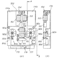
図3は、本発明の水中狭隘部移動システムの全体的構成の一例を示している。同図に示すように、狭隘部移動装置100、およびこの狭隘部移動装置100を内部に収納し移動する支援装置9を主たる構成要素とするものである。なお、支援装置9はケーブル10,11により制御統括システム12に接続されている。
【0025】
狭隘部移動装置100および支援装置9は、制御統括システム12の制御装置13および操作ボックス14により、作業員がモニター15を見ながら遠隔操作して移動させることができる。支援装置9は、4角の箱型状に形成され、上下移動用スラスタ16a,16bと、水平移動用スラスタ17a,17bとにより、水中を遊泳移動することができる。
【0026】
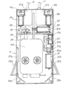
図4は、本発明の実施例における支援装置9の構成を示した正断面図である。この図4に示すように、支援装置9は、水中を遊泳移動するために、上下スラスタ16a,16bを駆動する駆動モータ18a,18bと、水平スラスタ17a(図示せず),17bを駆動する駆動モータ19bとを有する。
【0027】
そして、上下移動は、上下スラスタ16a,16bに直結された上下駆動モータ18a,18bを回転することにより行う。また水平移動は、水平駆動モータ19a(図示せず),19bに接続されたギア20a,20b、プーリ21a,タイミングベルト22を介してプーリ21bを回転させ、水平スラスト17a,17bを駆動することにより行う。以上の4つのスラスタで、炉内を自由に遊泳移動をすることができる。
【0028】
支援装置9の底部には、狭隘部移動装置100を収納する内部空間があり、この内部空間の上には、狭隘部移動装置100に結合されたケーブルの繰り出し、巻取りを行うためのケーブル巻取り装置23が配設されている。このケーブル巻取り装置23の駆動手段は、駆動モータ24、およびこの駆動モータ24の駆動軸に固定される溝付きプーリ25によって構成されている。
【0029】
この溝付きプーリ25は、図示しない他の溝付きプーリと対をなしており、これらの溝付きプーリで軽く押さえつつケーブルの繰り出し、巻取りを行う。また、駆動モータ24が万一故障した場合でも、原子炉圧力容器1の上部からケーブルを引き上げて、狭隘部移動装置100を支援装置9内に回収することができる。
【0030】
そして、支援装置9には、開口部を介して内部空間に回収した狭隘部移動装置100を保持する手段として、蝶番式扉26a,26bが配設されている。この蝶番式扉26a,26bは、エアシリンダ27a,27bを駆動することにより開閉される。このエアシリンダ27a,27bの駆動は、エアホース(図示せず)を通して制御装置13からエアを供給することにより行うことができる。
【0031】
さらに、支援装置9には、カメラ駆動装置28、監視カメラ29および水中ライト30が設けられており、狭隘部移動装置100の状態を制御統括システム12のモニター15で確認することができる。
【0032】
また、支援装置9内の上部には、支援装置9の水中バランスを維持するために、フロート31a,31bが配設されている。そして、支援装置9の外部に支援装置9をバッフルプレート4のアクセスホール5a,5bに位置決めするための位置決め手段として、位置決めガイド32a,32bがそれぞれ設けられている。
【0033】
図5は、支援装置9内における監視装置の構成を示す側面図である。監視装置は、カメラ駆動装置28および監視カメラ29で構成されている。カメラ駆動装置28は、駆動手段として、駆動モータ33と、この駆動モータ33の駆動軸に固定される溝付きプーリ34とを有し、この溝付きプーリ34は、図示しない他の溝付きプーリと対をなしており、これらの溝付きプーリで緩やかに押さえつつケーブルの繰り出し、巻取りを行う。
【0034】
このカメラ駆動装置28は、狭隘部移動装置100が、支援装置9から炉底部に繰り出された時に、監視カメラ29を支援装置9から炉底部に繰り出して、狭隘部移動装置100の状態を監視できるように構成されている。
【0035】
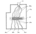
図6は、本発明の支援装置9におけるフロートの内部構成を示している。この図6は、フロート31aの縦断面図で、フロート31aには、操作ボックス14における制御装置13のケーブル11を取付けるための水中用コネクタ35と、支援装置9内部の各モータケーブルを取付けるための水中用コネクタ36a,36b,36c,36dとが設けられている。フロート31aの内部には、水中用コネクタ35、水中用コネクタ36a,36b,36c,36dに接続されるケーブル38a,38bおよび中継端子板37が設けられている。
【0036】
本実施例では、中継端子板37をフロート31a内に取付けたことにより、制御統括システム12の制御装置13からのケーブル10,11の本数を削減できる。よって、ケーブル10,11による支援装置9の移動時に与える負荷を軽減することができる。
【0037】
このように本実施例によれば、支援装置9が、狭隘部移動装置を搭載して水中を自由に遊泳移動できるため、事前準備であるジェットポンプのインレットミキサの取り外しをせずに、作業を効率的に行うことができる。
【0038】
次に、本発明の第1の参考例を図7に基づき説明する。
【0039】
まず、狭隘部移動装置100の具体的な構成について説明する。図7(a),(b)は、本参考例における狭隘部移動装置100(以下、単に移動装置100という。)の構成、形状を示す正面図、および一部側断面図である。この図7において、移動装置100は薄型に構成されており、筐体125内に各構成部材が配置されている。移動装置100の本体上部には、それぞれ上下スラスタ用モータ101a,101bにより駆動される上下移動用スラスタ102a,102bが配置されている。また移動装置100の本体下部には、水平スラスタ用モータ103a,103bが配置され、傘歯車とタイミングベルト104a,104bとを介して水平移動用スラスタ105a,105bを駆動する。
【0040】
そして移動装置100の本体中央には、車輪駆動モータ106a,106bと、これらのモータ106a,106bにより平歯車107a,107bを介して回転駆動される移動車輪108a,108bとが回転盤109a,109b上に設けられている。各回転盤109a,109bは、筐体125に対して回転可能に配置されており、各回転盤109a,109bは、ステアリングモータ110により、中間歯車111a,111bを介して同じ方向に回転駆動される。その回転角度は、ステアリングモータ110の出力軸と同じ歯車に噛み合って回転されるポテンショメータ112により計測される。
【0041】
回転盤109bの周縁部にはストライカ113が固定されており、回転盤109bの回転によるストライカ113の通過を、筐体125側に固定されたリミットスイッチ114により検出する。リミットスイッチ114の設置位置を、回転盤109bのある基準回転位置においてストライカ113を検出するように設定することで、移動車輪108a,108bの基準とする向きを定めることができる。装置本体の上部にはフロート120が配置されており、水中における装置本体の浮心を重心より上にすることができ、常に装置の姿勢を一定に保ちながら安定した遊泳移動をさせることできる。
【0042】
さらに、移動装置100の本体を水平移動用スラスタ105a,105bにより壁面へ押付けた時に、壁面との距離を一定に保つために4つのボールキャスタ130a〜130dが設けられている。
【0043】
移動装置100の本体下部には、点検作業を行うための水中カメラ175が設けられ、反射ミラー176により側方や下方の目視確認をすることができる。目視方向は、ミラー回転モータ177によって反射ミラー176を回転することにより、目視方向を変更、調整することができる。
【0044】
次に、本発明に係る狭隘部移動装置によりシュラウド・サポートレグ周りの溶接線検査を行う場合を例にして、装置の運用方法について説明する。
【0045】
まず移動装置100の本体に配置した4個のスラスタによって、シュラウド・サポートレグ8に向かって遊泳移動する。移動の仕方としては、炉内上部から上部格子板、炉心支持板を通過して当該箇所へ達する場合もあれば、途中経路の移動を迅速に行うために支援装置9内に収納されたままアクセスホール近傍に移送され、そこからシュラウド・サポートレグ8に向かって遊泳移動する場合もある。上下移動用スラスタ102a,102bにより浮上、潜行を行い、水平移動用スラスタ105a,105bにより前進、後進、左右旋回、その場旋回が可能であり、これら両者の動きを組み合わせることにより3次元遊泳移動を行うことができる。
【0046】
その後、シュラウド・サポートレグ8の検査対象箇所に、水平移動用スラスタ105a,105bにより装置本体を吸着させる。このスラスタ力が、シュラウド・サポートレグ8の壁面への押付け力となり、車輪回転時の走行駆動力となる。壁面に接触した後は、移動車輪108a,108bを車輪駆動モータ106a,106bにより回転駆動し、壁面上を移動する。
【0047】
移動方向は、ステアリングモータ110により回転盤109a,109bを回転させて移動車輪108a,108bの向きを変えることにより変更する。このように、車輪の回転駆動と車輪の向きを変えることによって壁面上の2次元移動が可能となる。水平、垂直のみでなく駆動方向を任意に設定することができる。この移動車輪が1つだけであると、壁面に接触した後に、ケーブル反力などを受けて装置全体が回転し搭載した各種装置や治工具の位置がずれてしまうが、車輪を2つにすることである程度のケーブル反力などに耐えることができ、装置の姿勢を保持することができる。
【0048】
このように本参考例によれば、上下移動用スラスタおよび水平移動用スラスタを組み合わせて作動させることにより、水中での3次元遊泳移動が可能である。また、炉内構造物に接触した後は、独立に回転駆動される2つの車輪を同時に、かつ同じ方向に向きを変えることができるので、精密な移動、位置決めを容易に実現することができる。その結果、炉下部のシュラウド・サポートレグやアニュラス部のジェットポンプ・アダプタ近傍の狭隘部などへ進入、移動し、溶接部の点検、検査、予防保全、補修といった各種作業を効率的に行うことが可能になる。
【0049】
図8および図9(a),(b)は、本発明の第2の参考例を示している。
【0050】
まず、狭隘部移動装置の具体的な構成について説明する。図8は、第2の参考例における狭隘部移動装置の構成、形状を示す正面図および一部側断面図である。この図8において、狭隘部移動装置は薄型に構成されており、筐体170に各構成部材が配置されている。上下移動用モータ150は、中間歯車151を介して上下移動用車輪152および上下移動用車輪153を回転駆動すると同時に、ギヤを介して上下移動用スラスタ154を回転駆動する。
【0051】
移動装置100の本体下部には、水平移動用モータ155が配置され、タイミングベルト156を介して水平移動用車輪157を回転駆動し、また中間歯車159を介して水平移動用車輪158を逆向きに回転駆動する。この水平移動用車輪157,158は、上下移動用車輪152,153と同じものである。移動装置100の本体下部両脇には、水平スラスタ用モータ160a,160bが配置され、傘歯車およびタイミングベルト161a,161bを介して水平移動用スラスタ162a,162bを回転駆動する。
【0052】
移動装置100の本体上部両脇には、フロート164a,164bが配置されており、水中における装置本体の浮心を重心より上にすることができるから、常に装置の姿勢を一定に保ちながら安定した遊泳移動ができる。
【0053】
さらに、移動装置100の本体を水平移動用スラスタ162a,162bにより壁面へ押付けた時に壁面との距離を一定に保つために、4つのボールキャスタ163a〜163dが取付けられている。
【0054】
移動装置100の本体下部には、点検作業を行うための水中カメラ175が設けられているから、反射ミラー176により、側方や下方の目視確認をすることができる。目視方向は、ミラー回転モータ177によって反射ミラー176を回転することにより、変更、調整を行うことができる。
【0055】
次に、本参考例に係る狭隘部移動装置によりシュラウド・サポートレグ周りの溶接線検査を行う場合を例にして、移動装置の運用方法について説明する。
【0056】
まずシュラウド・サポートレグへ移動装置100の本体に配置した3個のスラスタによって遊泳移動する。炉内上部から上部格子板、炉心支持板を通過して当該箇所へ達する場合もあれば、途中経路の移動を迅速に行うため支援装置内に収納されたままアクセスホール近傍に設置され、そこからシュラウド・サポートレグに遊泳移動する場合もある。
【0057】
上下移動用スラスタ154により浮上、潜行を行い、水平移動用スラスタ162a,162bにより前進、後進、左右旋回、その場旋回が可能であり、3次元遊泳移動を行うことができる。その後、シュラウド・サポートレグの検査対象箇所に、水平移動用スラスタ162a,162bにより装置本体を吸着させる。このスラスタ力がシュラウド・サポートレグ壁面への押付け力となり、車輪回転時の走行駆動力となる。壁面に当接した後は、上下移動用車輪152,153を回転させて上下方向に移動し、水平移動用車輪157,158を回転させて水平方向に移動する。これら二方向の移動機能により、壁面上の2次元移動が可能となる。
【0058】
次に、図8に示した移動用車輪による駆動力の発生原理について、図9(a),(b)を用いて説明する。
【0059】
図9(a)は、上下移動用のスラスタ154および上下移動用車輪152、ならびに上下移動用車輪153の駆動系構成の概略を示した模式図であり、図9(b)は車輪単体での駆動力の発生原理を説明する模式図である。この図9(a),(b)において、上下移動用車輪152,153は、円柱形状をした部材の表面にブラシ164がらせん状に植え込まれた構成となっている。さらに、上下移動用車輪152と上下移動用車輪153とでは、らせんの向きが互いに逆であり、中間歯車151により回転方向が反転されて駆動力が伝達される構成となっている。
【0060】
図9(b)は、上下移動用車輪153単体についての説明図である。この車輪153を壁面に押付けて右方向に180°回転させると、ブラシ164の先端が壁面上を車輪回転軸に対して垂直方向、水平方向にこすることによって、合力である壁面作用力181が発生する。上下移動車輪153側、すなわち装置本体側には、その反力182が走行駆動力として作用する。
【0061】
この反力182の方向は、ブラシ164のらせんのピッチに依存する。ピッチを小さくして、車輪一回転当りのブラシ164の先端と壁面との接触点が回転軸と平行な方向に移動する長さを、ブラシ164の植え込み長さに対してごく僅かに小さくすれば、単位回転速度での壁面上の接触点におけるブラシ164先端の速度は、回転軸と垂直な方向の成分に比べて回転軸方向の成分をかなり小さくすることが可能である。すなわち、ブラシを植え込むピッチを小さくすることによって、車輪を高速に回転しても回転軸と平行な方向に小さな駆動速度を発生させることが可能になる。
【0062】
一般的に、スラスタ力を発生させるためにはスラスタを高速に回転させる必要があるが、壁面に接触して車輪移動を行う場合には低速回転が必要になる。したがって、スラスタおよび車輪を同一の駆動源により駆動する場合には、駆動源と車輪回転軸との間に高比率の減速機を組み込まなければならず、駆動系の構造複雑化と動作効率の低下とを招く。
【0063】
それに換えて、図9(a)に示すような構成によれば、減速機を用いることなく壁面接触時の車輪による低速移動と、スラスタ154の高速回転による遊泳移動とが可能になる。図9(a)において、ブラシ164のらせんの向きを逆にした一組の上下移動用車輪152と上下移動用車輪153とを、互いに逆向きに回転駆動することによって左右対称の反力186が発生すると、車輪回転軸と垂直な方向の駆動力は相殺され、その合力である駆動力187が車輪の対称軸上で車輪回転軸と平行に発生する。
【0064】
前述したように、ブラシ164の植え込みピッチを小さくすることによって車輪の回転軸と平行な方向の駆動速度を小さくすることができるので、合力である駆動力187の方向、すなわちスラスタ力188と同じ方向に小さな駆動速度が与えられ、移動装置100の本体を低速移動させることができる。すなわち、一つの上下移動用モータ150により、減速機を用いずに、壁面接触時の車輪による低速移動と、スラスタを高速回転することによる遊泳移動とがともに実現可能である。
【0065】
このように本参考例によれば、一つの駆動源と簡易な駆動構成によりスラスタによる遊泳移動と車輪による走行移動とが可能になるので、装置に搭載する駆動源を減らすことができ、装置を薄く小型にまとめることが容易になる。その結果、炉下部のシュラウド・サポートレグやアニュラス部のジェットポンプ・アダプタ近傍の狭隘部へ進入、移動して溶接部の点検、検査、予防保全、補修といった各種作業を効率的に行うのに好適な炉内移動装置を提供することができる。
【0066】
同時に、ケーブル芯数、またはケーブル本数を減らすことができるので、装置移動時の負荷が小さくなって移動性能の低下を防ぎ、かつ装置の信頼性を向上させることができる。
【0067】
上記実施例では、原子炉を適用対象として説明したが、火力発電所等における、水が満たされた狭隘部の監視、補修を要する装置や、さらには船舶の推進機構周辺等にも本発明を適用することができる。
【0068】
【発明の効果】
本発明は上述のように、移動制御および位置決めが迅速、的確に行われ、水が満たされた装置内各部での各種作業を効率的に行うことができる。
【図面の簡単な説明】
【図1】 原子炉の圧力容器内の構造と構造物のうち、炉下部を示す横断面図。
【図2】 原子炉の圧力容器内の構造と構造物のうち、本発明に関連する部位を示す縦断面図。
【図3】 本発明による炉内移動システムを示す図であって、図3(a)は支援装置9および移動装置100の構成を示す斜視図、図3(b)は制御装置13および関連機器の説明図。
【図4】 本発明の実施例における支援装置の構成を詳細に示す正面図。
【図5】 同実施例における支援装置の内部に設置した監視装置の構成を示す平面図。
【図6】 同実施例における支援装置の内部に取付けたフロートの構成を示す縦断面図。
【図7】 図7(a)は本発明の第1の参考例における狭隘部移動装置の構成、形状を示す正面図、図7(b)は同じく一部側断面図。
【図8】 図8(a)は本発明の第2の参考例における炉内内狭隘部移動装置の構成、形状を示す正面図、図8(b)は図8(a)のA−A線に沿った一部側断面図。
【図9】 図9(a)は、本発明の第2の参考例における上下移動用のスラスタおよび上下移動用車、上下移動用車輪の駆動系構成の概略を示す模式図、図9(b)は同参考例における移動用車輪単体での駆動力の発生原理を説明する模式図。
【符号の説明】
1 原子炉圧力容器
9 支援装置
10 電源ケーブル
11 信号ケーブル
12 制御統括システム
13 制御装置
14 操作ボックス
16 上下移動用スラスタ
17 水平移動用スラスタ
18 上下スラスタ駆動モータ
19 水平スラスタ駆動モータ
23 ケーブル巻取り装置
28 カメラケーブル駆動装置
29 監視カメラ
30 水中ライト
31 フロート
33 カメラケーブル駆動モータ
37 中継端子板
38 ケーブル
100 狭隘部移動装置
101 上下スラスタ用モータ
102 上下移動用スラスタ
103 水平スラスタ用モータ
105 水平移動用スラスタ
106 車輪駆動モータ
108 移動車輪
110 ステアリングモータ
120 フロート
150 上下移動モータ
152 上下移動用車輪
153 上下移動用車輪
154 上下移動用スラスタ
155 水平移動用モータ
157 水平移動用車輪
158 水平移動用車輪
160 水平スラスタ用モータ
162 水平移動用スラスタ
164 ブラシ
175 水中カメラ[0001]
BACKGROUND OF THE INVENTION
The present invention relates to an apparatus for performing inspection, inspection, preventive maintenance, and repair in an apparatus filled with water, and in particular, transporting, positioning, holding, and moving various apparatuses and jigs to narrow places inside and outside the apparatus. It relates to a device for performing.
[0002]
[Prior art]
For example, the in-core structure of a nuclear reactor, particularly a boiling water reactor, is made of a material having sufficient durability and high-temperature strength in a high-temperature and high-pressure environment, such as austenitic stainless steel or a nickel-based alloy.
[0003]
Of these in-furnace structures, those parts that are difficult to replace are exposed to harsh environments due to long-term plant operations and are also affected by neutron irradiation, so there is a concern about material degradation problems. The In particular, in the vicinity of the welded portion of the furnace internal structure, there is a risk of potential stress corrosion cracking due to the sensitization of the material due to welding heat input and the influence of tensile residual stress.
[0004]
The shroud support, which is the core support structure, has similar concerns. In particular, the area under the baffle plate (shroud support leg) in the shroud support at the bottom of the furnace and the vicinity of the jet pump adapter in the annulus are inspected and repaired. Need to be preserved.
[0005]
Conventionally, in order to inspect, inspect, and repair each part of the reactor pressure vessel and reactor internals, various devices and jigs have been installed to move or move while adsorbing to the wall. Yes. That is, various devices and jigs are transported by these devices, the position to the object is determined, the position is held, and the position is moved minutely.
[0006]
In order to perform inspections, inspections, repairs, etc. in narrow spaces such as the shroud support leg in the lower part of the furnace and the jet pump / adapter in the annulus, it is necessary to install a mobile device equipped with various devices and jigs. It is necessary to make it thin and small, and it is necessary to perform a swimming movement on the functional surface and a wall surface movement that moves while contacting the target wall surface.
[0007]
[Problems to be solved by the invention]
Since the swimming movement is a three-dimensional movement, at least three thrusters are required, and since the wall movement is a two-dimensional movement, at least two driving sources are required. However, a large number of drive sources hindered the thinning and miniaturization of the moving device, and a multi-core cable or multiple cables would increase the load during movement and reduce the moving performance, thereby improving the reliability of the device. Inconveniences such as lowering.
[0008]
Even if the moving device is made thin and small, in order to inspect, inspect and repair the bottom of the furnace, as a preparation, access from the core side, removal of the control rod guide tube, and access from the annulus part side The work such as the removal of the jet pump inlet mixer is required, which takes a lot of time.
[0009]
The present invention has been made in view of the above-described points, and an object thereof is to provide an underwater narrow part moving system including a narrow part moving device having a moving function of moving to an arbitrary position on a wall surface.
[0010]
To achieve the above object, the present invention claims 1 The invention described herein is provided.
[0015]
According to the first aspect of the present invention, the working device is mounted, and the narrow portion moving device that can move in the narrow portion filled with water, the opening for allowing the narrow portion moving device to enter and exit, and the narrow portion moving device are held. A support device having a holding means and capable of moving while performing a support operation for the narrow part moving device, and releasing the holding by the holding means in the support device when necessary, and through the opening, the narrow part To move in and out of mobile devices Composed In the underwater narrow section moving system, the support device provides an underwater narrow section moving system having a cable winder that feeds and winds a cable for taking in and out the monitoring camera.
[0020]
DETAILED DESCRIPTION OF THE INVENTION
Examples of the present invention And reference examples This will be described with reference to the drawings.
[0021]
First, with reference to FIG. 1 and FIG. 2, a work target location of the underwater narrow portion moving system according to the present invention and a structure in the vicinity thereof will be described. FIG. 1 shows a cross section of the lower part of a boiling water reactor, which includes a donut-shaped
[0022]
FIG. 2 shows a longitudinal sectional view of the core of the boiling water reactor. As shown in FIG. 1, a
[0023]
As shown in FIG. 2, the
[0024]
FIG. 3 shows an example of the overall configuration of the underwater narrow part moving system of the present invention. As shown in the figure, the narrow
[0025]
The narrow
[0026]
FIG. 4 illustrates the present invention. Example It is the front sectional view which showed the structure of the
[0027]
The vertical movement is performed by rotating the
[0028]
There is an internal space for accommodating the narrow
[0029]
The grooved
[0030]
The
[0031]
Further, the
[0032]
In addition, floats 31 a and 31 b are disposed in the upper portion of the
[0033]
FIG. 5 is a side view showing the configuration of the monitoring device in the
[0034]
This
[0035]
FIG. 6 shows the internal structure of the float in the
[0036]
In the present embodiment, the number of
[0037]
in this way Example According to the present invention, since the
[0038]
Next, the present invention First reference example Will be described with reference to FIG.
[0039]
First, a specific configuration of the narrow
[0040]
At the center of the main body of the moving
[0041]
A
[0042]
Furthermore, four
[0043]
An
[0044]
Next, the operation method of the apparatus will be described by taking as an example a case where a weld line inspection around the shroud support leg is performed by the narrow part moving apparatus according to the present invention.
[0045]
First, the four thrusters arranged in the main body of the moving
[0046]
Thereafter, the apparatus main body is adsorbed to the inspection target portion of the
[0047]
The moving direction is changed by rotating the
[0048]
in this way Reference example According to the above, by operating the thruster for vertical movement and the thruster for horizontal movement in combination, three-dimensional swimming movement in water is possible. Further, since the two wheels that are independently driven to rotate can be changed in direction in the same direction after contacting the in-furnace structure, precise movement and positioning can be easily realized. As a result, it is possible to enter and move to the shroud support leg in the lower part of the furnace and the narrow part near the jet pump adapter in the annulus, etc., and efficiently perform various operations such as inspection, inspection, preventive maintenance, and repair of welds. It becomes possible.
[0049]
8 and 9 (a) and 9 (b) show the present invention. Second reference example Is shown.
[0050]
First, a specific configuration of the narrow part moving device will be described. FIG. Second reference example FIG. 2 is a front view and a partial side sectional view showing the configuration and shape of the narrow part moving device in FIG. In FIG. 8, the narrow part moving device is configured to be thin, and each component member is arranged in a
[0051]
A
[0052]
Floats 164a and 164b are arranged on both sides of the upper part of the main body of the moving
[0053]
Further, four
[0054]
Since the
[0055]
next, Reference example The operation method of the moving device will be described by taking as an example a case where the weld line inspection around the shroud support leg is performed by the narrow portion moving device according to the above.
[0056]
First, swimming is carried out to the shroud support leg by three thrusters arranged on the main body of the moving
[0057]
The
[0058]
Next, the principle of generating the driving force by the moving wheel shown in FIG. 8 will be described with reference to FIGS. 9 (a) and 9 (b).
[0059]
FIG. 9A is a schematic diagram showing an outline of the drive system configuration of the vertically moving
[0060]
FIG. 9B is an explanatory diagram of the
[0061]
The direction of the
[0062]
Generally, in order to generate a thruster force, it is necessary to rotate the thruster at a high speed. However, when the wheel is moved in contact with the wall surface, a low-speed rotation is required. Therefore, when the thruster and wheels are driven by the same drive source, a high-ratio reduction gear must be incorporated between the drive source and the wheel rotation shaft, resulting in a complicated drive system structure and reduced operating efficiency. Invite you.
[0063]
Instead, according to the configuration shown in FIG. 9A, low-speed movement by the wheel when contacting the wall surface and swimming movement by high-speed rotation of the
[0064]
As described above, by reducing the implantation pitch of the
[0065]
in this way Reference example According to the present invention, it is possible to perform swimming movement using a thruster and traveling movement using wheels with a single drive source and a simple drive configuration, so that the number of drive sources mounted on the apparatus can be reduced, and the apparatus can be reduced in size and size. It becomes easy. As a result, it is suitable for efficiently performing various operations such as inspection, inspection, preventive maintenance, repair of welded parts by entering and moving to the narrow part of the shroud support leg at the bottom of the furnace and the jet pump / adapter near the annulus. Can be provided.
[0066]
At the same time, since the number of cable cores or the number of cables can be reduced, the load during movement of the apparatus can be reduced to prevent a decrease in movement performance, and the reliability of the apparatus can be improved.
[0067]
In the above embodiment, the nuclear reactor has been described as an application target, but the present invention is also applied to a device requiring monitoring and repairing a narrow part filled with water in a thermal power plant or the like, and also to the vicinity of a propulsion mechanism of a ship. Can be applied.
[0068]
【The invention's effect】
As described above, according to the present invention, movement control and positioning are performed quickly and accurately, and various operations in each part in the apparatus filled with water can be efficiently performed.
[Brief description of the drawings]
FIG. 1 is a cross-sectional view showing a lower part of a structure and structures in a pressure vessel of a nuclear reactor.
FIG. 2 is a longitudinal sectional view showing a part related to the present invention among structures and structures in a pressure vessel of a nuclear reactor.
3A and 3B are diagrams showing an in-furnace moving system according to the present invention, in which FIG. 3A is a perspective view showing configurations of the
FIG. 4 of the present invention Example The front view which shows the structure of the assistance apparatus in detail.
FIG. 5 is a plan view showing a configuration of a monitoring device installed inside the support device according to the embodiment.
FIG. 6 is a longitudinal sectional view showing the structure of a float attached to the inside of the support device in the same embodiment.
FIG. 7 (a) is an illustration of the present invention. First reference example The front view which shows the structure and shape of a narrow part moving apparatus in FIG. 7, FIG.7 (b) is a partial sectional side view similarly.
FIG. 8 (a) is an illustration of the present invention. Second reference example FIG. 8B is a partial cross-sectional side view taken along the line AA of FIG. 8A. FIG.
FIG. 9 (a) shows the present invention. Second reference example FIG. 9B is a schematic diagram showing an outline of the drive system configuration of the vertical movement thruster, vertical movement vehicle, and vertical movement wheel in FIG. Reference example The schematic diagram explaining the generation | occurrence | production principle of the driving force in the wheel for movement in this.
[Explanation of symbols]
1 Reactor pressure vessel
9 Support equipment
10 Power cable
11 Signal cable
12 Control system
13 Control device
14 Operation box
16 Thruster for vertical movement
17 Thruster for horizontal movement
18 Vertical thruster drive motor
19 Horizontal thruster drive motor
23 Cable winding device
28 Camera cable drive
29 surveillance cameras
30 Underwater light
31 Float
33 Camera cable drive motor
37 Relay terminal board
38 cables
100 Narrow part moving device
101 Vertical thruster motor
102 Thruster for vertical movement
103 Horizontal thruster motor
105 Thruster for horizontal movement
106 Wheel drive motor
108 Moving wheels
110 Steering motor
120 float
150 Vertical movement motor
152 Wheel for vertical movement
153 Vertical movement wheel
154 Thruster for vertical movement
155 Horizontal movement motor
157 Horizontal movement wheel
158 Horizontal movement wheels
160 Horizontal thruster motor
162 Thruster for horizontal movement
164 brush
175 Underwater camera
Claims (1)
前記狭隘部移動装置を出入りさせる開口部および前記狭隘部移動装置を保持する保持手段を有し、前記狭隘部移動装置に対する支援動作を行いつつ移動しうる支援装置とを備え、所要時に前記支援装置における前記保持手段による保持を解除し、前記開口部を介して前記狭隘部移動装置を出入りさせるよう構成される水中狭隘部移動システムにおいて、
前記支援装置は、前記監視カメラを出し入れするためのケーブルの繰り出し、巻取りを行うケーブル巻取り機を有することを特徴とする水中狭隘部移動システム。A narrow part moving device that is equipped with work equipment and can move in a narrow part filled with water,
A support device that has an opening through which the narrow portion moving device enters and exits and a holding means that holds the narrow portion moving device, and that can move while performing a support operation for the narrow portion moving device, and the support device when necessary In the underwater narrow part moving system configured to release the holding by the holding means in and to allow the narrow part moving device to enter and exit through the opening,
The support device includes a cable winder that feeds and winds a cable for inserting and removing the surveillance camera.
Priority Applications (1)
| Application Number | Priority Date | Filing Date | Title |
|---|---|---|---|
| JP2001231508A JP4090712B2 (en) | 2001-07-31 | 2001-07-31 | Underwater narrow part movement system |
Applications Claiming Priority (1)
| Application Number | Priority Date | Filing Date | Title |
|---|---|---|---|
| JP2001231508A JP4090712B2 (en) | 2001-07-31 | 2001-07-31 | Underwater narrow part movement system |
Publications (3)
| Publication Number | Publication Date |
|---|---|
| JP2003040194A JP2003040194A (en) | 2003-02-13 |
| JP2003040194A5 JP2003040194A5 (en) | 2005-10-27 |
| JP4090712B2 true JP4090712B2 (en) | 2008-05-28 |
Family
ID=19063553
Family Applications (1)
| Application Number | Title | Priority Date | Filing Date |
|---|---|---|---|
| JP2001231508A Expired - Fee Related JP4090712B2 (en) | 2001-07-31 | 2001-07-31 | Underwater narrow part movement system |
Country Status (1)
| Country | Link |
|---|---|
| JP (1) | JP4090712B2 (en) |
Families Citing this family (7)
| Publication number | Priority date | Publication date | Assignee | Title |
|---|---|---|---|---|
| JP4546746B2 (en) * | 2004-02-19 | 2010-09-15 | 株式会社日立製作所 | Inspection device, inspection device input device, and inspection method |
| JP4599095B2 (en) * | 2004-05-27 | 2010-12-15 | 株式会社東芝 | In-reactor inspection equipment |
| JP2007057357A (en) * | 2005-08-24 | 2007-03-08 | Toshiba Corp | Inspection maintenance method of reactor inside |
| JP4984497B2 (en) * | 2005-11-10 | 2012-07-25 | 株式会社日立製作所 | Underwater inspection device |
| JP4965867B2 (en) | 2006-02-13 | 2012-07-04 | 株式会社東芝 | Underwater mobile repair inspection device and underwater mobile repair inspection method |
| JP5295546B2 (en) * | 2007-10-19 | 2013-09-18 | 株式会社東芝 | In-reactor inspection and repair device and control method thereof |
| CN108263573A (en) * | 2016-12-30 | 2018-07-10 | 核动力运行研究所 | A kind of nuclear power plant's sucked type float assembly |
-
2001
- 2001-07-31 JP JP2001231508A patent/JP4090712B2/en not_active Expired - Fee Related
Also Published As
| Publication number | Publication date |
|---|---|
| JP2003040194A (en) | 2003-02-13 |
Similar Documents
| Publication | Publication Date | Title |
|---|---|---|
| CN102421571B (en) | Inspection system and inspection process utilizing magnetic inspection vehicle | |
| JP2007212393A (en) | Underwater moving apparatus for repair and inspection | |
| JP4090712B2 (en) | Underwater narrow part movement system | |
| US20030128794A1 (en) | Device and method for repairing inside of reactor pressure vessel | |
| JP4112891B2 (en) | In-reactor transfer device | |
| US6528754B2 (en) | Underwater maintenance repair device and method | |
| JP7389196B2 (en) | Reciprocating device | |
| JP2007003442A (en) | Ut inspection method and device for nozzle weld zone of reactor vessel | |
| US8848857B2 (en) | Preventive maintenance/repair device and preventive mainenance/repair method for cylindrical structure | |
| US5982839A (en) | Assemblies and methods for inspecting piping of a nuclear reactor | |
| JPH1114784A (en) | Reactor internal inspecting device | |
| US6536283B1 (en) | Assemblies and methods for inspecting piping of a nuclear reactor | |
| JP2007003400A (en) | Inspection device for control rod through-hole member | |
| JP2008116421A (en) | Underwater inspection apparatus and method | |
| JP3871464B2 (en) | Remote handling equipment for reactor internals | |
| JP4047260B2 (en) | In-furnace work robot | |
| JP4000032B2 (en) | Furnace bottom working device and working method | |
| JP3146101B2 (en) | Reactor inspection equipment | |
| JP5295546B2 (en) | In-reactor inspection and repair device and control method thereof | |
| JP4585079B2 (en) | Working device and working method | |
| JP3306040B2 (en) | Reactor internal structure maintenance and repair equipment | |
| JPH11311692A (en) | Remote in-core work device and method therefor | |
| JPH08146186A (en) | Nuclear reactor internal structure inspection device and inspection method | |
| JP4383920B2 (en) | In-furnace maintenance and repair equipment | |
| JP4746273B2 (en) | In-furnace work system |
Legal Events
| Date | Code | Title | Description |
|---|---|---|---|
| A521 | Written amendment |
Free format text: JAPANESE INTERMEDIATE CODE: A523 Effective date: 20050726 |
|
| A621 | Written request for application examination |
Free format text: JAPANESE INTERMEDIATE CODE: A621 Effective date: 20050726 |
|
| A977 | Report on retrieval |
Free format text: JAPANESE INTERMEDIATE CODE: A971007 Effective date: 20070622 |
|
| A131 | Notification of reasons for refusal |
Free format text: JAPANESE INTERMEDIATE CODE: A131 Effective date: 20070629 |
|
| A521 | Written amendment |
Free format text: JAPANESE INTERMEDIATE CODE: A523 Effective date: 20070823 |
|
| A02 | Decision of refusal |
Free format text: JAPANESE INTERMEDIATE CODE: A02 Effective date: 20071023 |
|
| A521 | Written amendment |
Free format text: JAPANESE INTERMEDIATE CODE: A523 Effective date: 20071213 |
|
| A911 | Transfer of reconsideration by examiner before appeal (zenchi) |
Free format text: JAPANESE INTERMEDIATE CODE: A911 Effective date: 20071228 |
|
| TRDD | Decision of grant or rejection written | ||
| A01 | Written decision to grant a patent or to grant a registration (utility model) |
Free format text: JAPANESE INTERMEDIATE CODE: A01 Effective date: 20080222 |
|
| A61 | First payment of annual fees (during grant procedure) |
Free format text: JAPANESE INTERMEDIATE CODE: A61 Effective date: 20080227 |
|
| FPAY | Renewal fee payment (event date is renewal date of database) |
Free format text: PAYMENT UNTIL: 20110307 Year of fee payment: 3 |
|
| FPAY | Renewal fee payment (event date is renewal date of database) |
Free format text: PAYMENT UNTIL: 20120307 Year of fee payment: 4 |
|
| FPAY | Renewal fee payment (event date is renewal date of database) |
Free format text: PAYMENT UNTIL: 20130307 Year of fee payment: 5 |
|
| FPAY | Renewal fee payment (event date is renewal date of database) |
Free format text: PAYMENT UNTIL: 20130307 Year of fee payment: 5 |
|
| FPAY | Renewal fee payment (event date is renewal date of database) |
Free format text: PAYMENT UNTIL: 20140307 Year of fee payment: 6 |
|
| LAPS | Cancellation because of no payment of annual fees |