JP4090585B2 - Heat treatment method for target object and apparatus therefor - Google Patents
Heat treatment method for target object and apparatus therefor Download PDFInfo
- Publication number
- JP4090585B2 JP4090585B2 JP22049398A JP22049398A JP4090585B2 JP 4090585 B2 JP4090585 B2 JP 4090585B2 JP 22049398 A JP22049398 A JP 22049398A JP 22049398 A JP22049398 A JP 22049398A JP 4090585 B2 JP4090585 B2 JP 4090585B2
- Authority
- JP
- Japan
- Prior art keywords
- target object
- heat treatment
- heat
- gas
- temperature
- Prior art date
- Legal status (The legal status is an assumption and is not a legal conclusion. Google has not performed a legal analysis and makes no representation as to the accuracy of the status listed.)
- Expired - Fee Related
Links
Images


Description
【0001】
【発明の属する技術分野】
本発明は、加熱処理方法および装置に関し、種々の製品の製造あるいは処理において、原料、中間品あるいは最終製品に加熱処理を施すための方法および装置に関する。
【0002】
【従来の技術】
種々の製品の生産において、様々な加熱処理が利用されている。具体的には、乾燥、脱水、焼成、反応促進、表面改質等の加熱処理によって達成される作用は数多く知られている。加熱処理の効率を向上させるために、加熱処理の対象物体をコンベア等で搬送しつつドーム状あるいはトンネル状の加熱空間内を通過させて加熱処理を施すことが実施されている。
【0003】
そのような加熱処理を実施する装置は、対象物体の移動(または移送)方向に沿って、対象物体を加熱して熱処理を開始すべき温度まで昇温させる昇温ゾーンおよび昇温した対象物体を所定の熱的環境にさらす(例えば昇温された温度を所定時間維持する、または昇温された温度から所定の温度変化に付す)熱処理ゾーンを有して成り、これらのゾーンの境界が明らかでない場合もある。本明細書においては、加熱処理とは、このような昇温および熱処理の双方を含むものとして使用している。更に、上述のような加熱処理を実施する装置は、一般的に、熱処理後に対象物体を所定の温度まで降温させる冷却ゾーンを熱処理ゾーンの後に有する。対象物体は、これらのゾーンを順に通過していく。
【0004】
【発明が解決しようとする課題】
ところが、上述の加熱処理方法では、加熱処理装置に供給される熱エネルギーのうち、対象物体の加熱処理自体に消費される熱エネルギーの割合が少なく、供給した熱エネルギーの大部分が浪費されるという、熱エネルギーの利用効率が低いというの問題があり、加熱処理のコストが高くつく原因になっている。
【0005】
従来の加熱処理方法において、熱エネルギーの利用効率が低い原因は、例えば次の理由が考えられる:
対象物体を移動するコンベアが出入りするトンネル状の加熱処理空間では、出入口が常に開放されているため、加熱装置に供給された熱エネルギーの一部分が出入口から放出されてしまう。このような出入口からの熱エネルギーの放出は、加熱装置に供給された熱エネルギーの約30%程度にもなると言われている。
加熱処理空間内では、対象物体に加えてコンベアをも加熱することになるため、コンベアのような移動機構を加熱するために多くの熱エネルギーが必要とされる。コンベアのような移動機構は、複雑であり、また、熱容量も大きく、そのようなコンベアを加熱するには大量の熱エネルギーが必要である。コンベアは、加熱前から加熱後まで対象物体を移動するため、コンベアが加熱空間を出ると、加熱炉内でコンベアに供給された熱エネルギーは外部に放出されてしまい、無駄になる。コンベアが加熱処理空間を循環して出入りする毎に、大量の熱エネルギーをコンベアに供給し、供給された熱エネルギーを利用することなく外部に放出していることになる。このようなコンベアによる熱エネルギーの持ち出しは、供給された熱エネルギーの約20%程度にもなると言われている。
【0006】
更に、従来の加熱処理装置では、加熱処理空間を構成する壁から外部に放出される熱エネルギーの量も大きく、供給された熱エネルギーの約45%程度が加熱処理空間の壁から放出されてしまうと言われている。
結果として、従来の加熱処理方法では、供給された熱エネルギーのうち、対象物体の加熱処理に実際に利用できる熱エネルギーは、全体のわずか5%またはそれ以下に過ぎないと言われている。
そこで、本発明の課題は、従来における加熱処理方法の問題点を解消し、熱エネルギーの利用効率を向上させることにある。
【0007】
【課題を解決するための手段】
本発明は、対象物体を加熱処理するための方法を提供し、この方法は、加熱処理空間において対象物体の下方から対象物体に向かって気体を吹き付けることによって浮揚させた状態で所定のように対象物体を加熱することを特徴とする。
【0008】
本発明において加熱処理とは、対象物体に熱を加えるいずれの処理であってもよく、この加熱処理によって、対象物体の少なくとも1つの特性(例えば、水分保有率、電気抵抗、透過率、形成膜厚またはその均一性、応力等)が所定のように変化する。例えば、加熱処理は、対象物体の温度を所定の温度まで所定時間で上げる処理、対象物体の温度を所定温度で所定時間維持する処理および/または対象物体を所定の温度変化条件にさらす処理等を含む。加熱処理は、上述のように熱を加える処理であるが、加熱処理の期間中、常に熱を加えている必要は必ずしもなく、熱を加えない時があってもよく、その場合、放熱等によって、加熱処理温度が低下してもよい。
【0009】
また、対象物体とは、加熱処理する対象である。対象物体は、いずれの形態であってもよく、従って、複雑な形態であってもよい。一般的には、対象物体は、全体としてプレート、シートまたはフィルム状形態等(これらは、長尺帯状等の連続形態であっても、定尺に分割された形態であってもよい。)を有し、水平方向の寸法(またはディメンション)がそれに垂直な方向の寸法(即ち、厚さ)に比べて相当大きいものが好ましい。尚、本明細書において、水平方向とは、シート状形態の対象物体を規定する主表面が広がる方向を意味する。対象物体は、主表面の一方または双方に凹凸部が存在しても、全体としての対象物体がシート状形態等であるのが好ましい。
【0010】
対象物体を構成する材料は、特に限定されるものではなく、例えばセラミック、ガラス、金属、樹脂、その他の構造材料、またはこれらのいずれかの組み合わせから対象物体が構成されていてよい。本発明の1つの態様では、上述のような対象物体を少なくとも2つ組み合わせることによって対象物体が形成されていてもよく、その場合、組み合わせにより形成された対象物体は、シート状形態であっても、より複雑な形態であってもよい。
具体的には、加熱処理には例えば乾燥、脱水、焼成、反応、反応促進、表面改質、燒結、熱硬化、熱融解、接着等が含まれる。そのような処理における対象物体には、例えば半導体基板、PDP(plasma display panel)基板、太陽電池基板、液晶基板、CRT(テレビブラウン管)等が含まれる。
【0011】
本発明の方法において、対象物体に気体を吹き付けることによって対象物体を浮揚させるということは、対象物体を気体中に浮いた状態にすることを意味する。対象物体に向かってその下方から気体を吹き付けて気体が対象物体に衝突することによって生じる、気体が対象物体を上向きに押す力(気体の動圧力または静圧力)が、対象物体に作用する重力と釣り合うようにすることによって、対象物体を周辺気体中で浮揚させる。通常、対象物体の下から対象物体の下面(底面)に向かって、それに対して垂直に気体を送気口から噴出させて対象物体を持ち上げるようにする。対象物体の下面に加えて、対象物体の上面および/または側面に向かって気体を吹き付けることによって、対象物体の姿勢を調節することも可能である。
【0012】
更に、対象物体の下面に気体が当たる方向を下面に対して垂直ではなく、斜めにすると、その気体によって対象物体に、水平方向の分力および垂直方向の分力に分割できる力が作用する。この水平方向の分力は、対象物体が停止している場合には、対象物体をその分力の方向に移動させ、対象物体が既に移動している場合には、分力の向きに応じて対象物体の移動速度を加速または減速するように作用する。例えば、移動している対象物体に、その移動方向と逆方向の分力を作用させるように気体を吹き付けると、対象物体の移動を減速させたり停止させたりすることができる。垂直方向の分力は、対象物体を浮揚させるのに使用される。
【0013】
対象物体への気体の吹き付けは、送気口としての開口部を介して対象物体に向かって気体を供給することにより実施する。通常、加熱処理空間内において、対象物体が位置する箇所、および位置することになる箇所の下に(即ち、対象物体の移動経路に)、複数、好ましくは多数の送気口が設けられ、対象物体に対して同じ方向から、または異なる方向から気体が当たるように実施してよい。このような場合、送気口を介して供給される気体によって対象物体を押すように作用する力の合力が、水平方向の分力を有する時には、その分力の方向に対象物体は移動する。
【0014】
具体的には、対象物体の下面の複数箇所に垂直かつ上向きに気体を吹き付けるように送気口を加熱処理空間内に設けてもよく、別の態様では、対象物体の下面のある箇所には、垂直かつ上向きに気体を吹き付け、別の箇所には斜めかつ上向きに気体を吹き付けるように送気口を加熱処理空間内に設けてもよい。どのように気体を吹き付けるか(従って、どのように送気口を設けるか)は、対象物体をどのように浮揚して、必要に応じてどのように移動するかということに応じて、当業者であれば本明細書の開示に基づいて容易に選択できる。
【0015】
従って、本発明の加熱処理方法において、対象物体は、加熱処理の間、浮揚状態で上述のように移動してもよく、あるいは浮揚状態で停止していてもよい。更に、浮揚状態で停止および移動を組み合わせてもよい。例えば、加熱処理方法は、浮揚状態で停止させて加熱処理して、その後、浮揚状態で移動させながら更に加熱処理するシーケンスを含んでも、あるいはこの逆のシーケンスを含んでもよい。浮揚した対象物体を停止させるか、あるいは移動するかは、対象物体に対する必要な加熱処理の種類に応じて選択できる。
【0016】
本発明において、移動および停止とは、対象物体の水平方向に沿った実質的な距離の移動の有無に関する。停止とは、対象物体が少なくとも水平方向に移動しない状態(従って、垂直方向には移動しても、あるいはしなくてもよい)を意味する。移動とは、対象物体が少なくとも水平方向に移動する状態(従って、垂直方向には移動しても、あるいはしなくてもよい)を意味する。
【0017】
所定の加熱処理を長時間にわたって実施する場合には、対象物体を所定箇所にて停止状態で浮揚させて加熱処理し、その後、対象物体を移動するのが好ましく、加熱処理空間が小さくてすむ。また、短時間の加熱処理の場合には、加熱処理空間で浮揚状態で連続的に(好ましくは一定速度で)移動させながら、加熱処理を実施するのが好ましく、処理効率が高くなる。このような2つの方法を組み合わせる、即ち、停止状態で加熱処理し、かつ、移動状態で加熱処理することも可能である。
【0018】
別法では、加熱空間内で対象物体を気体によって浮揚させた状態で気体によって移動させて、加熱処理自体は、対象物体が浮揚していない状態(例えば、垂直方向に機械的に支持されている状態)で実施してもよい。1つの好ましい態様では、加熱空間内で気体によって対象物体を浮揚させながら、対象物体の移動は対象物体に機械的に力を加えて実施してよく、この場合に、加熱処理は、対象物体を移動中および停止中、またはこれらのいずれかの時に実施してよい。
【0019】
対象物体の浮揚に使用する気体は、対象物体の加熱処理に悪影響を与えない、あるいは加熱を促進するものであれば、いずれの気体であってもよい。一般的には、空気、加熱雰囲気を構成するための気体、例えば窒素等の不活性ガス、反応性ガスまたはそれらの混合物等を使用できる。これらの気体は、加熱処理温度に応じて、適当に加熱されているのが好ましく、その場合は、加熱処理および気体の浮揚の双方を同時に実施できる。高温の気体である燃焼ガスも、対象物体に悪影響を与えない場合には使用できる。
【0020】
気体は、上述のように送気口を通って対象物体に向かって噴出されるが、送気口は、所定の圧力を所定方向で対象物体に作用できるように気体を供給できるものであれば、特に限定されるものではない。送気口は、例えばノズル、スリット、メッシュ等の形態であってよく、断面形状も特に限定されるものではなく、例えば円形、楕円形、矩形等であってよい。通常、対象物体を浮揚させた状態で移動する加熱処理空間内の経路に沿って複数、好ましくは多数の送気口が設けられ、対象物体が浮揚した状態で加熱処理空間を通過できるようになっている。
【0021】
一般的に、送気口を列および/またはカラム状に(即ち、移動経路に沿った方向および/またはそれに垂直な方向で列状に)多数対象物体の移動経路に設ける。例えば、格子状に送気口を設けてよい。送気口の数およびその配置は、加熱処理空間、特にその中で対象物体が通過する経路(長さ、幅等)、ならびに処理すべき対象物体に応じて、特にその重量(単位底面積当たりの重量)および幅、ならびに浮揚すべき高さ等に応じて、適当に選択できる。尚、浮揚すべき高さ(即ち、対象物体と送気口との距離)は、対象物体が円滑に移動できる限り、いずれの高さであってよく、一般的には0.1〜20mm程度であってよく、浮揚用気体の消費量に伴なうコスト低減と対象物体の熱変形による搬送工程の信頼性を高めることを考慮すれば通常0.5〜3mm程度であってよい。
【0022】
上述のように対象物体を気体によって浮揚させる方式(気体浮揚方式)を使用する場合、加熱処理空間内には、送気口およびそれに到る導管を実質的に配置するだけでよく、気体の供給機構(例えばポンプ、バルブ、コントロールシステム等)を加熱処理空間の外部に配置でき、従って、加熱処理室内の設備は非常に簡単になる。その結果、加熱処理装置に関連する故障も減少し、メンテナンスも楽になる。換言すれば、気体浮揚方式を用いると、複雑な機械的動作機構を高温の加熱処理空間内に配置する必要がないという利点がある。
尚、上述のように気体を用いて対象物体を浮揚させて移動すること自体は、例えば特開昭61−267394号公報、特開平2−76242号公報、特開平5−29238号公報等に開示されており、これらの特許文献の開示事項は、この引用により本明細書の一部分を構成する。
【0023】
本発明の1つの好ましい態様では、上述のように、浮揚した対象物体の移動に関して、気体の吹き付けではなく、機械的な手段(または力)を用いて実施する。加熱処理温度が高くなると、気体の密度が小さくなり、対象物体の浮揚に加えて移動をも気体を用いて実施しようとすると、非常に大量の気体を供給する手段を設置しなければならない場合がある。そのような場合には、対象物体の浮揚のみを気体によって実施し、水平方向の移動は、機械的な力を用いて実施する。
【0024】
例えば、対象物体を移動する方向に、機械的な力を浮揚対象物体に瞬間的に加える(例えば単に押す)と、対象物体は加えられた力の方向に移動しようとする。その時、対象物体が移動して行く経路に沿って存在する送気口から、移動してくる対象物体に向かって次々に気体を噴出させると、その気体が対象物体を順に支持することになる。対象物体は気体と接触して浮揚しているだけであり、対象物体と気体との間の摩擦力は小さく、下から吹き出す気体は、対象物体の下側で一種のベアリングの作用をするので、対象物体は実質的に最初の押す力だけで少なくとも幾らかの距離をその時の条件に応じて移動できる。通常、移動する対象物体の速度は徐々に低下し、最終的には停止する。移動している対象物体をその途中で停止させるには、例えば移動方向の延長線上に存在する障害物に衝突させ、対象物体の持つ運動エネルギーを障害物に吸収させることにより実施できる。
【0025】
尚、押す力の大きさを変えると、移動速度および/または移動距離を変えることができる。このように対象物体を押すこと、また、止めることに使用する手段の構造および動作は比較的簡単であり(例えば単なる構造体でよい)、作用する力も小さくて済む。
【0026】
別法では、対象物体を移動すべき所定方向と同じ方向に加熱処理空間を移動する少なくとも1つの当接要素(またはストッパー要素)を加熱処理空間に設け、移動する当接要素が浮揚した状態の対象物体の一部分に当接してそれを拘束し、その結果、当接要素が対象物体を所定方向に押し続けることによって対象物体を移動させるようにする。対象物体は、当接要素により拘束されているので、当接要素の移動を停止することによって、対象物体の移動を停止することができる。また、当接要素の移動速度を変えることにより、加熱処理空間内における対象物体の移動速度をコントロールすることができる。このような当接要素は、加熱処理空間において対象物体の移動経路の少なくとも片側で、好ましくは移動経路の両側で移動する駆動手段に設ける。移動するチェーン、ベルトのような連続的な駆動手段に締結されているのが好ましく、そのような駆動手段の運転/停止に対応して当接手段が移動/停止し、その結果、対象物体が移動/停止する。
【0027】
更に別の態様では、連続して対象物体を処理する場合には、加熱処理空間において相互に隣接して配置され、また、気体によって浮揚され得る複数の支持要素(例えばキャリアトレイ)を準備し、支持要素のそれぞれに対象物体を配置して、第1支持要素を加熱処理空間の入口に配置し、その後、第2支持要素を第1支持要素に当接させ、第2支持要素に力を加え、その力を隣接する第1支持要素に伝達して第1支持要素を移動させて加熱処理空間内に押し込むと同時に、第2支持要素を加熱処理空間入口に配置する。次に、先と同様に、第3支持要素を加熱処理空間入口に配置して第2支持要素に当接させ、第3支持要素を加熱処理空間の入口に配置することによって、先行する第2支持要素および既に加熱処理空間に入っている第1支持要素を移動方向に向かって更に前進させる。このような操作を繰り返すことによって、先行する支持要素が後続の支持要素によって押されて加熱処理空間内を移動するようにする。この場合、支持要素は加熱処理空間内において、下から吹き付ける気体により浮揚状態にある。この方式は、プラグフロー(plug flow)方式(あるいはトコロテン方式(押出式)またはプッシュ方式)と呼ぶことができ、後続の支持要素が先行する支持要素を機械的に押す。この方式では、対象物体を有する支持要素は、間欠的に移動する。即ち、浮揚している支持要素は、後続の支持要素が押し込まれる時に、移動し、押し込みが完了すると、停止する。
【0028】
上述のように、種々の方式で移動する対象物体(またはそれを含むキャリヤ要素)を停止するには、先に説明した停止方法とは別に、あるいはそれに加えて、吸引停止手段を使用して移動している対象物体(またはそれを含むキャリヤ要素)を停止することができる。この吸引停止手段は、浮揚している対象物体を停止させるべき箇所に設け、対象物体は吸引停止手段上に向かって引き寄せられ(従って、対象物体は一定位置で浮揚した状態で停止する)、場合によっては対象物体が吸引停止手段に吸着するようにする。例えば対象物体が浮揚している雰囲気、特に対象物体の下方から気体を吸引する吸引口を設け、これを吸引停止手段として使用できる。
【0029】
具体的には、対象物体の移動経路の所定箇所に気体の吸引口を配置し、その吸引口から対象物体の周辺の気体を吸引することによって、吸引口の上を通過しようとする対象物体が吸引口に向かって引き寄せられ、対象物体の動きを止めることができる。吸引口には、ポンプ等の気体を吸引する装置を連結しておくことができる。この際、吸引力が大きく、対象物体を浮揚させようとする送気口からの気体の圧力に優る場合には、対象物体の浮揚状態を維持できないことになる。従って、浮揚状態を保持しながら気体を吸引する場合には、送気口から気体を吹き出す量を多くする必要がある。この場合、対象物体の動きが止まると、気体の吸引を停止すると共に、送気口から吹き出す気体の量を減らす必要がある。
【0030】
このような吸引停止手段の一例として、本体部および摺動部材を備えた以下に説明する、いわゆるエジェクター方式の吸引停止手段を採用できる。本体部は、その一端から加圧気体が供給され、他端から加圧気体が放出される加圧気体路、および加圧気体路の途中から分岐して対象物体の移動経路に向かって開口する吸引口を有する吸引路を有する。摺動部材は、吸引口が開口する本体部の端部を覆い、本体部から対象物体に向かう方向で摺動自在に嵌挿されている。
【0031】
この吸引停止手段では、加圧気体が加圧気体路を通過すると、その動圧で吸引路に吸引力が発生し、摺動部材の吸引口から気体を吸い込むようになっている。摺動部材の吸引口に対象物体が近づくと、対象物体と摺動部材との間の空間が低圧になり、摺動部材が対象物体に引き寄せられる。すると、対象物体と摺動部材との間の空間がますます狭くなり、その結果、この空間の圧力が一層低圧になり、摺動部材が対象物体に吸着される。その結果、対象物体の移動は、摺動部材が取り付けられた本体部によって停止される。その後、加圧路への加圧気体の供給を中止すれば、摺動部材は本体部側に戻り、対象物体は自由に移動できるようになる。このような吸引停止手段において、対象物体が摺動部材に吸着する直前に加圧気体の供給を停止すれば、対象物体と摺動部材が接触することなく、対象物体は浮揚状態のままで実質的に停止することができる。
【0032】
本発明では、上述のような浮揚および必要な移動を加熱処理空間内において実施しながら、対象物体を加熱処理する。尚、一般的には、加熱処理に引き続いて加熱処理温度からより低い温度に対象物体の温度を下げる降温操作を実施する。このような降温操作においても、必要に応じて、上述のような対象物体の浮揚および移動の方式を採用できるのは言うまでもない。
【0033】
従って、本発明の加熱処理装置は、昇温ゾーンおよび熱処理ゾーンを有する加熱処理空間、ならびに場合により降温ゾーンを有して成る。昇温ゾーンとは、対象物体の温度を初期温度から所定の熱処理開始温度まで、好ましくは所定時間で、上げる領域であり、熱処理ゾーンとは、所定の熱処理開始温度まで加熱された対象物体を、好ましくは所定時間、所定温度条件下に保持する領域である。所定条件とは恒温の場合であっても、所定のように温度が変化する条件(加熱量を減らした、または加熱を停止した結果として、あるいは熱損失の結果として温度が下がる場合も含む)であってもよい。また、降温ゾーンとは、対象物体の温度を熱処理温度から、好ましくは所定時間で、所定の温度まで下げる領域である。
【0034】
対象物体が通過する間に、対象物体の温度が昇温されて熱処理される加熱処理空間は、通常の加熱処理装置において採用されている加熱処理空間と同様の構造であってよい。一般的には、加熱処理空間は、断熱壁材で囲まれたドーム状あるいはトンネル状形態であり、対象物体が加熱処理空間の入口に配置され、その後、加熱処理空間を対象物体が通過する。対象物体を加熱処理空間の入口において気体を吹き付けることによって浮揚させる。その後の対象物体の移動および停止は、上述のいずれの方法を適用してもよい。例えば、浮揚している対象物体の下面に気体を斜め方向から吹き付けて移動させてよく、機械的な力により対象物体を移動させてもよく、あるいは、対象物体を載せることができるキャリヤ要素上に対象物体を載せて、プッシュ方式で移動させてもよく、これらを組み合わせることも可能である。
【0035】
加熱処理空間では、対象物体の移送経路に沿って、昇温ゾーンおよび熱処理ゾーンに適当な加熱手段を設ける。加熱手段は、対象物体に加熱処理に使用できるいずれの適当な常套の手段であってもよい。加熱手段の数および配置は、加熱空間の大きさ、加熱処理の種類等に応じて適当に選択できる。加熱手段は全て同じタイプであってもよいし、加熱処理の目的に応じて異なるタイプであってもよい。加熱処理空間における断熱構造についても、昇温ゾーンおよび熱処理ゾーンでは、同じであっても、異なってもよい。
加熱処理空間への入口およびそれからの出口には、空間内部とその周囲との間で加熱処理空間内の雰囲気ガスおよび熱の移動を抑制するために、遮蔽手段を設けてよい。例えば、遮蔽手段には、機械的に開閉する扉装置のほか、エアカーテンが採用できる。
【0036】
尚、上述のように、必要に応じて、加熱処理空間の下流側に、降温ゾーンを設けてよい。加熱処理が施された対象物体は、降温ゾーンにおいて、加熱処理空間を出た後、自然放冷によって降温させてもよいし、強制的に降温させることもでき、あるいは両者を組み合わせることもできる。降温操作は、対象物体を、常温まで降温させてもよいし、常温よりも高い所定の温度まで降温させるだけでもよい。
【0037】
強制的な降温手段として、気体の吹きつけが行われる。基本的には、使用する気体の温度は対象物体の温度よりも低ければよい。好ましい態様では、降温を複数のステップで実施し、各ステップの気体の温度は、段階的に低くなり、温度の高い気体から順に段階的に対象物体に吹きつけることによって、対象物体の温度を段階的に下げるようにすれば、対象物体に熱歪みなどの障害を発生させることなく、迅速な降温が可能になる。
【0038】
降温ゾーンに要する装置スペースを削減するため、降温ゾーンにおいては、隣接する対象物体の主表面が空間部を隔てて積み重なるように配置して(即ち、複数の対象物体を主表面が隣接し、それらの間に空間部が存在するように間隔をあけて重ねた状態で)移動させながら(即ち、対象物体の主表面に対して垂直な方向に移動させながら)冷却降温させることができる。対象物体をこのように重ねると、加熱処理におけるように対象物体をその主表面方向に並べて降温する場合と比較して、降温ゾーンに必要な設置スペースが少なくて済む。
【0039】
従って、例えば加熱処理空間における対象物体の上述のような水平方向の移動と、対象物体を重ねて垂直方向に移動して段階的に温度が低い気体の吹きつける降温とを組み合わせることができる。主表面に垂直な方向に間隔を隔てて重ねられた対象物体の間隔毎に気体を吹きつけて対象物体間を気体が通過するようにすれば、対象物体の両面から迅速に冷却が行われる。
【0040】
本発明の加熱処理装置の加熱処理空間において、均熱シートを使用するのが特に好ましい。
均熱シートとは、熱伝導性の良いシート状材料であり、特に好ましいのは、熱伝導に異方性を有し、かつ熱伝導性の良いシート状材料である。このような均熱シートは、シート材料に全体にわたって温度分布をより均一にし易い材料である。従って、加熱処理装置において、均熱シートを使用すると、使用しない場合と比較して、均一な加熱を容易に達成することができる。本明細書において、均一な加熱とは、完全に均一であるという意味ではなく、均熱シートを使用しない場合と比較して、加熱の均一の程度が相対的に向上するという意味である。
均熱シートとしては、主表面方向に熱を良好に伝達する材料が好ましく、例えば、一般的に熱伝導性の良い金属(例えば銅)、無機材料(例えばガラス、セラミック等)、炭素材料等が用いられる。
【0041】
特に好ましい態様では、均熱シートとしてグラファイトシートを使用する。グラファイトシートは、耐熱性が高く熱伝導性にも優れている。グラファイトシートの中でも、高配向グラファイトシートが好ましい。この高配向グラファイトシートは、ポリイミド樹脂等の樹脂シートを焼成してグラファイト化したものであり、配向性が高く、厚み方向に比べて面方向に非常に高い熱伝導性を有していると共に、3000℃以上の耐熱性を有している。具体的には、特開平3−75211号公報に開示されているものをこのグラファイトシートとして適用でき、この特許公開の内容は、この引用により本明細書の一部を構成する。
【0042】
本発明の加熱処理装置の加熱処理空間において、加熱手段と対象物体との間に均熱シートを配置しておけば、加熱手段により発生する熱を均熱シート全体に一様に分配して、対象物体の全体を均等かつ迅速に加熱することが可能になる。また、均熱シートを加熱手段の外側に配置しておけば、加熱手段から放出される熱のうち、その外側に向かって放出される熱を均熱シートの全面に均一に分配することができ、均熱シートの全面からその内側に存在する対象物体を均等に加熱することができる。その結果、加熱手段から外側に逃げる熱を効率的に利用できることになる。
【0043】
均熱シートは、加熱手段と対象物体との間、および、加熱手段の外側の両方に配置しておくこともできる。均熱シートは、加熱手段として、局部的に高い熱を発生する加熱手段、例えば火炎等を採用した場合に特に有効となる。また、高熱を発生する加熱手段で対象物体を短時間に加熱昇温させる際に、加熱ムラや熱歪みを発生させないために有効である。熱処理ゾーンで、対象物体の全体を所定の温度範囲に確実に維持するためにも有効である。
【0044】
更に、1つの好ましい態様では、局所的に加熱可能な加熱手段の外側に全体的に加熱可能な加熱手段を配置し、これらの加熱手段の間に均熱シートを配置する。具体的には、均熱シートと対象物体との間に電気ヒータを配置し、均熱シートの外側に熱媒体流通管を配置しておくことが有効である。熱媒体流通管で発生した強い熱エネルギーを均熱シートで均一化して対象物体の全体を均等に加熱するとともに、電気ヒータで精密な温度制御を行えば、加熱処理空間において対象物体の全体を一定の温度に加熱することが容易になる。このような加熱機構は、熱処理ゾーンで特に有効である。
均熱シートの配置は、加熱処理空間において対象物体が移動される経路を包囲するように実施するのが好ましい。このようにすると、均熱シートの内側空間では、対象物体に対して熱エネルギーが均等に供給されるので、迅速かつ均一な加熱が可能になる。
【0045】
より好ましい態様では、対象物体の周囲を均熱シートで二重に囲み、2層の均熱シートの間に加熱手段を配置して加熱すれば、加熱手段で発生する熱が効率的に内外の均熱シートに伝達されて均熱シートの全体に均一に拡がり、均熱シートの全体から対象物体の全体を均等に加熱することができる。
均熱シートの一部に熱を供給して、均熱シートの特性によって全面に熱を伝達させ、均熱シートを介して対象物体を加熱してよい。この場合では、熱の供給源としての加熱手段を対象物体の移動経路や対象物体に近い場所に配置しなくても、均熱シートを介して対象物体に効率的に熱エネルギーを供給することができる。
【0046】
本発明の加熱処理装置の加熱処理空間の壁面は断熱材を用いて構成される。この断熱材は、一般的に使用されている材料から形成されていてよく、また、断熱材の構造も一般的に使用されているものと同じであってよい。断熱材の材料としては、例えば耐熱レンガ、耐熱ガラス、耐熱セラミックス等が用いられる。
断熱材として、内部に高真空空間を有する断熱材を使用するのが好ましい。真空空間は熱伝達を遮断するため、そのような断熱材の断熱性は極めて高い。
【0047】
1つの好ましい態様では、断熱材を構成する表面のうち、対象物体の移動経路に面する表面に赤外線反射膜を形成する。この態様では、断熱材を通過しようとする熱エネルギーを、赤外線反射膜によって対象物体に向けて効率的に反射させることができる。赤外線反射膜として、例えば金属酸化膜、SiO2/TaOx多層膜、セラミック材等の所望の反射波長特性を有する材料等を使用できる。
【0048】
別の好ましい態様では、断熱材は、互いに連結自在な断熱ブロックの形態である。そのようなブロック形態とすれば、加熱処理空間の構造の設計および製造が容易になる。断熱ブロック同士の連結は、ブロック自体が相互に嵌合し、および/または係合するような構造にすることによって実施してよい。別法では、別の連結金具を用いて連結することも可能である。例えば、断熱ブロックを加熱処理空間の内壁面に金具等で取り付けることもできる。
【0049】
断熱材またはそれにより構成される壁の内面側(即ち、対象物体に面する側)および/または外面側(即ち、内面側に対向する側)に均熱シートを配置しておくことが好ましい。従って、断熱材を断熱ブロックにより構成する場合には、断熱ブロックの内面側および/または外面側に均熱シートを貼り付けたものを用いることもできる。
【0050】
本発明の加熱処理装置の加熱処理空間は、断熱材が対象物体の移動経路を包囲するマッフル構造にするのが好ましい。マッフル構造は、通常の加熱装置におけるマッフルと同様の構造が適用できる。
【0051】
本発明の加熱処理装置における対象物体の加熱に際しては、いずれの適当な手段により加熱してもよい。一般的には、加熱手段としては、通常の加熱処理装置における加熱手段が採用できる。1つの態様では、加熱処理空間内において可燃性ガスを燃焼させて火炎を発生させ、この火炎で加熱することができる。対象物体と直接に対向するように火炎を発生させると、火炎により生じる燃焼ガスの熱の火炎の周辺雰囲気における熱対流および熱伝導による加熱、ならびに火炎からの熱放射による加熱を対象物体の加熱処理に利用できる。火炎による加熱を行うには、対象物体の搬送経路に可燃性ガス(例えば水素、都市ガス、LPG等の可燃性燃料)を放出して点火する燃焼口を配置しておけばよい。
例えば、対象物体を浮揚させるための気体の送気口に隣接させて燃焼口を配置しておき、気体の送気方向に沿って火炎が生じるようにすると、火炎によって発生する熱を、浮揚のための気流によって対象物体に効率的に供給することができる。
【0052】
別の態様では、別の場所で可燃性ガスを燃焼させて発生した高温の燃焼ガスを加熱処理空間に供給してその中の雰囲気の温度を上げてもよい。燃焼ガスを加熱処理空間の雰囲気に供給するのではなく、加熱処理空間の雰囲気ガスを高温の燃焼ガスと熱交換することにより、加熱処理空間の雰囲気の温度を上げてもよい。更に別の態様では、加熱手段として、電気ヒータ、赤外線ランプ等の電気的な加熱手段を使用する。電気ヒータは供給電力を調節することによって発生する熱量を迅速かつ容易に調節できるという利点がある。
【0053】
更に、別の加熱手段として、熱媒体流通管が使用できる。熱媒体流通管は、中空管に高温ガス、高温の油等の熱媒体を流通させて、中空管の外側に放出される熱を加熱処理に利用する。熱媒体流通管は強い熱エネルギーを発生することができると共に、熱媒体は対象物体に接触しないので、熱媒体が対象物体に悪影響を与えることがない。
【0054】
【発明の実施の形態】
添付図面を参照して、本発明をより具体的に説明する。
図1に本発明の加熱処理方法に使用する加熱処理装置1を斜視図にて模式的に示す。加熱処理装置1は、昇温ゾーンX、熱処理ゾーンYおよび降温ゾーンZを有して成り、矩形プレート状の対象物体Pが、矢印によって示すように、昇温ゾーンXに供給され、熱処理ゾーンYおよび降温ゾーンZを経て装置から排出される。昇温ゾーンXおよび熱処理ゾーンYが加熱処理空間10を構成する。加熱処理空間10は、図示するように、その入口にエアーカーテンを設けることにより、内部を外部から遮断している。例えば、ガラス基板、セラミック材、金属材等からなる対象物体Pに膜形成材料(例えば銀ペースト、SnO2やITO(indium-tin oxide)等の透明導電性膜、蛍光体、誘電体、絶縁体、半導体)を塗布した後の焼成に図示した装置を使用できる。
例えば、プラズマ・ディスプレイ・パネルを製造する際に、種々の段階において基板に塗布された(例えばスキージー印刷)された種々のペースト材料(例えば銀ペースト、蛍光体(R・G・B発色材料)ペースト、誘電体(例えばガラス、MgO)ペースト)を種々の段階で焼成するために、使用できる。
【0055】
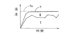
本発明の加熱処理における温度条件は、いずれの適当な温度変化を含むものであってもよい。例えば、図2に示すように、加熱処理空間(即ち、昇温ゾーンXおよび熱処理ゾーンY)内において、対象物体Pの温度は、まず、昇温ゾーンXで常温から所定の加熱温度T0まで急速に(例えば所定時間t1で)上げられ、その後、熱処理ゾーンYでは、昇温された温度T0が(例えば所定時間t2の間)維持される。加熱処理が終了すると、降温ゾーンZでは、加熱処理を終えた対象物体Pが例えば図示するように段階的に温度を(例えば所定時間t3で)下げられた後、装置から排出される。
【0056】
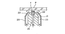
図3に本発明の加熱処理方法に用いる加熱処理空間10の一部分をその中の様子が理解できるように斜視図にて模式的に示す。図示した態様は、特に昇温ゾーンに使用するのが特に好ましい。加熱処理空間10は、対象物体Pを挿入するには十分であるが、それほど広くない幅の開口部14を有する(また、開口部14の高さについても同様である)。加熱処理空間10の内側には、複数、好ましくは多数の浮揚部材20が対象物体Pの(矢印により示す)搬送方向に沿って間隔を隔てて配置されている。各浮揚部材20は、対象物体の移動方向に対して垂直な方向に沿って長尺であり、その幅(即ち、浮揚部材20の長手方向の長さ)は対象物体Pの幅(W、移動方向に対して垂直な方向の長さ)よりも少し広く設定されている。
隣り合う浮揚部材20同士の間には排気部材27が配置され、従って、浮揚部材20と排気部材27が交互に並列し、浮揚部材20に隣接する排気部材27の一方には吸引停止手段30が配置されている。この吸引停止手段30は、対象物体Pの幅方向の両端近くに配置されているが、吸引停止手段の数および配置は必要に応じて適当に選択してよい。排気部材27は浮揚部材20と同じ幅を有し、下方に配置された排気管28に連通している。浮揚部材20には、対象物体の幅方向(矢印W)に沿って図示するようにスリットまたは複数の送気口が設けられ、その送気口から気体を対象物体Pに向かって吹き出すことによって対象物体を浮揚させる。
【0057】
尚、図3に示す浮揚部材20は、後述するように、その中央に燃焼口の列を有し、そこから火炎fが生じる。排気部材27には、対象物体の幅方向に沿って複数の排気口が設けられており、加熱処理空間内から気体を排気口を介して吸い込むことにより、加熱処理空間内の所定の条件(例えば圧力またはその中の気体の量等)を所定のように維持する。吸引停止手段30は、後述するように、移動している対象物体を停止させることができる。
【0058】
図4に浮揚部材20の断面図(対象物体の主表面に対して垂直な方向で、かつ、対象物体の移動方向に沿った断面図)を模式的に示す。浮揚部材20は、中央に燃焼口24を有し、その両側に送気口22が配置されている。図示するように、送気導管23を通ってきた気体が送気口22からその上方に存在する対象物体Pに向かって吹き付けられる。送気導管23は、加熱処理空間10の外部に設置された送気管26に接続されている(図3参照)。送気管26は予め加熱された気体、例えば空気を供給するのが好ましい。気体の加熱は、加熱処理空間10から排出される気体との熱交換により実施してよく、熱エネルギーを有効に利用できる。別法では、加熱処理空間10から排気される気体をそのまま送気管26を経由して再使用してよい。
【0059】
図4に示す態様では、一対の送気口22は浮揚部材20の中央に向かって斜め方向に気体を吹き出し、対象物体Pに当たった気体が対象物体Pに沿って外側に流れる。その際に発生する浮揚力で対象物体Pが浮揚する。
燃焼口24には、加熱処理空間10の外部から導管25を通じて可燃性ガスが供給される。この可燃性ガスは、燃焼口24で燃焼して火炎fを発生する。火炎fは、左右の送気口22、22からの気流に挟まれた形で、対象物体Pに向かって実質的に真っ直ぐに延びる。火炎fは、周囲の気体を加熱して、昇温した気体が対象物体Pに接触して対象物体を加熱する作用と、火炎fから放射される熱線で直接に対象物体Pを加熱する作用との両方で、対象物体Pを加熱して所定温度まで急速に昇温させるか、あるいは対象物体の所定温度を維持する。尚、火炎fは、送気口22、22から吹き出す気流を加熱する作用も有する。
【0060】
図3および図4に示した態様では、加熱処理空間10の開口部から内部に送り込まれた対象物体Pは、浮揚部材20から吹きつけられる空気で浮揚させられ、燃焼口24からの火炎で加熱される。図3に示すように、浮揚部材20から吹き出した気体および燃焼口24における燃焼ガスは、排気部材27の排気口および排気管28を通じて外部に排気される。排気に含まれる熱エネルギーを回収して、対象物体Pを浮揚させるための気体を昇温させたり、後述するように、降温部Zで使用する気体を加温するのに利用できる。
尚、図示した態様では、浮揚部材20は、対象物体Pを浮揚させるだけで、水平方向に移動させたり停止せたりする搬送機能は備えていない。
【0061】
本発明の加熱処理方法において、浮揚した対象物体を移動させる方法を説明するために、対象物体を移動する方向に対して垂直な横方向から見た様子を図5に示している。図示した態様では、対象物体Pは右から左に向かって移動する。対象物体Pの移動経路の右端に、軸回転可能なプッシュアーム48が配置されている。プッシュアーム48は、加熱処理空間10を横断して軸支された旋回軸46に支持されている。対象物体Pが移動経路の右端に存在する状態(図の右側に示す対象物体P)で、プッシュアーム48が水平状態(二点鎖線で示す)から右回りに旋回すると、アームの先端が対象物体Pの縁部に当接する位置に配置される。対象物体Pの縁部に当接したアーム48を更に旋回させると、アーム48は対象物体Pを左方向に押し、それによって、対象物体は、図5の右から左に向かって移動する。浮揚状態の対象物体Pはアーム48で軽く押すだけで移動する。移動させる距離および速度に応じて、回転軸の回転速度を調節することによって、アーム48が押す力を変えることができる。例えばアーム48が対象物体に衝突するように軸46を回転しても、あるいは対象物体を穏やかに押すように軸46を回転してもよい。
【0062】
また、図5において、対象物体の搬送経路の左端にストップアーム(止め要素)49が軸回転できるように旋回軸47に配置されている。対象物体Pが移動している時に、アーム49は図示するように垂直状態であり、移動してきた対象物体は、アーム49に衝突してそれ以上は移動できず停止する。対象物体の移動速度が大きい場合には、対象物体が衝突した瞬間にアーム49が移動している対象物体の運動エネルギーを吸収して右回りに回転するようにすると、衝突した反動によって、対象物体が跳ね返されるのを避けることができる。
上述のようなアーム48および49の動作を適宜に組み合わせて行うことで、対象物体Pを所定の方向に移動させたり移動速度を変えたり停止させたりすることが容易に行える。
【0063】
更に、もう1つの態様において、図6に模式的に示すように、本発明の加熱処理方法では浮揚した対象物体を機械的な力を用いて移動させる。尚、図6(a)では、斜視図にて、図6(b)では平面図にて示している。
図6では、対象物体Pの移動方向(矢印)に動くチェーンまたはベルトのような駆動手段200が対象物体Pの移動経路202の両側に配置され、浮揚した対象物体Pに当接する部材204をそのような駆動手段に締結する。対象物体を移動すべき方向に駆動手段が移動すると、当接要素204は対象物体Pを押すことになり、それによって、対象物体は移動する。駆動手段200を停止すると、当接要素204は停止し、従って、対象物体Pを押さないので、浮揚した状態で対象物体は停止する。このような駆動手段を加熱処理空間10内に配置する。当接要素は、対象物体を移動すべき方向に向かって対象物体を押すように、対象物体の後方に配置するが、対象物体の前方に追加的な当接要素206として配置してもよく、そのようにすると、対象物体を確実に停止できる。
当接要素は、少なくとも1つ設けることにより、その目的を達成できるが、処理すべき対象物体に応じて数を増やしたり、あるいは当接要素自体の構造を適当に変えることができる。通常、対象物体の後縁208の両端付近で当接するのが好ましく、従って、図6(a)に示すように、2個の当接要素を使用するのが好ましい。対象物体の幅が大きい場合には、後縁208の中央部付近に当接要素を設けてもよいし、左右の当接要素204がつながっていてもよい。
【0064】
このような駆動手段を加熱処理空間に配置する場合、加熱処理空間の対象物体の移動経路の側方に設けたチェーンまたはベルトのような簡単な駆動手段を配置するだけでよいこと、駆動手段に動力を作用する複雑な装置は、加熱処理空間の外部に配置できること、また、気体を用いて対象物体を移動し、吸引停止手段を使用して移動する対象物体を停止する時と比較して、気体を使用せずに対象物体の移動および停止を確実にできるという利点がある。
【0065】
また、更に別の態様において、気体によって浮揚でき、また対象物体を支持できる支持要素に入れ、その支持要素を加熱処理空間内で移動させて加熱処理する。この方式を図7に加熱処理空間の模式的断面図にて示す。
例えば図示するようにキャリヤトレイの形態であってよい支持要素210は、相互に隣接・接触して複数個が配置され、その中に加熱処理すべき対象物体Pを配置する。支持要素は、対象物体の移動すべき方向に対して垂直な方向に沿って、対象物体の厚さより十分に大きいディメンション(または深さ)を有し、隣接した支持要素の最後尾において対象物体を移動すべき方向に力を加えると、その力は、最後の支持要素からそれに隣接する先行の支持要素に伝達され、更に、その支持要素から更に先行の支持要素に伝達される、というように力が順に伝達されるようになっている。従って、最後の支持要素を前方に向かって押すことにより、それに先行する全ての支持要素を移動させることができる。このような移動機構はプッシュ方式(またはプラグフロー方式)とも呼ぶことができ、これを加熱処理空間10内に配置すると、支持要素に配置した対象物体が順次加熱処理空間を移動し、その間に加熱処理されることになる。支持要素自体は、その下に位置する送気口から吹き付けられる気体によって浮揚されるので、支持要素を移動させるために必要な力は、少なくてすむ。図6を参照して説明した態様では、対象物体が垂直方向に変位する場合、または当接要素の厚さが十分でない時、当接要素が対象物体に容易に当接できないことがある。これに対して、図7の態様では、隣接する支持要素が十分に大きい垂直方向ディメンションを有し、その結果、支持要素の間で確実に力を伝達できるので、そのような問題がなく、対象物体を確実に移動できるので特に有効である。
【0066】
別の態様では、移動している対象物体の停止は、図3に示す吸引停止手段30により実施してもよい。吸引停止手段30の作用を説明するために、図8に吸引停止手段30の断面図(対象物体の移動方向で対象物体に対して垂直な方向の断面図)を模式的に示す。吸引停止手段30は、例えば円柱状の本体部31およびその先端に配置された円筒キャップ状の摺動部材40により構成され、摺動部材40は、本体部31の先端で矢印で示すように上下方向に摺動自在に取り付けられている。本体部31は、その下方部に水平方向に貫通する加圧気体路33を有する。加圧気体路33の一端には、導管53が連結され、導管53には、制御弁54およびポンプ52が連結されている。ポンプ52および制御弁54は、加熱処理空間10の外部に配置される。ポンプ52の作動によって、加圧気体(例えば空気)を加圧気体路33に送り込む。加圧気体路33の他端には、外部に開放された放出口34が存在し、加圧気体路33に送り込まれた気体は放出口34から外部に放出される。
本体部31は、その中央部に吸引気体路32を有する。吸引気体路32の下端は、加圧気体路33につながっている。吸引気体路32の上端は、本体部31の先端にて開口している。本体部31の吸引気体路32の上端の上方では、摺動部材40の中央部に貫通孔42が形成されている。
【0067】
上述のような構造を有する吸引停止手段30の動作を次に説明する。
図8(A)に示すように、加圧気体路33を高圧の気体が通過すると、その動圧による吸引作用で、吸引気体路32内の気体が吸引される。吸引気体路32の上端からは摺動部材40の貫通孔42を介して上方空間の気体が吸引される。
図8(B)に示すように、吸引停止手段30の上方に対象物体Pがあると、対象物体Pの下面と摺動部材40の上面との間の気体が貫通孔42に吸引され気流が発生することで、対象物体Pと摺動部材40との間の空間の圧力が低下する。そうすると、上下方向に摺動可能な摺動部材40は対象物体P側に吸い上げられて、上方に移動する。摺動部材40が上方に移動すると、対象物体Pとの間の隙間が更に狭くなり、気流は速く圧力は低くなるので、摺動部材40は一層対象物体Pに吸いつけられる。
図8(C)に示すように、摺動部材40が対象物体Pの下面に接触してしまうと、摺動部材40の貫通孔42に吸い込まれる気流は無くなる。但し、加圧気体路33を加圧気体が通過することで、吸引気体路32側の気体を吸引する作用は続くので、摺動部材40は対象物体Pの下面に強く吸着された状態になる。本体部31に取り付けられた摺動部材40は水平方向には移動できないから、摺動部材40と対象物体Pとの間の摩擦抵抗力で対象物体Pの移動が阻止される。
尚、加圧気体路33への高圧気体の供給を中止すれば、吸引気体路32に対する吸引作用は無くなるので、摺動部材40は自重で下方に移動する。この時、送気口から対象物体Pに向かって気体が吹き付けられている場合には、対象物体Pは摺動部材40から離れて浮揚状態に戻る。この状態で、対象物体Pに水平方向に移動させる何らかの力が作用すると、対象物体Pは水平方向に移動できる。
【0068】
このような吸引停止手段30は、加圧気体の供給・停止を制御するだけで、加熱処理空間10の内部には複雑な機構を備えていなくても、迅速かつ確実な対象物体Pの停止および停止解除を果たすことができる。複雑な機構を加熱処理空間内に設ける必要がなければ、高温の加熱処理空間10内でも安定した動作が可能である。
【0069】
対象物体を移動させる別の態様を説明するために、対象物体の移動をコントロールする送気部材の断面図(対象物体の移動方向で対象物体に対して垂直な方向の断面図)を図9に模式的に示す。
送気部材50は、対象物体Pの搬送方向(図示した態様では、矢印で示すように右から左に向かう方向)に対して斜め方向に(従って、右下から左上に向かう方向に)気体を吹き出す。具体的には、送気部材50には、導管52を介して制御弁56およびポンプ54が連結されており、送気部材50の先端には対象物体Pに対して斜め方向に向いた送気口51を有する。
制御弁56を開いて送気口51から対象物体Pに向けて気体を吹きつけると、対象物体Pには、右下から左上に向かう方向の圧力が作用し、その圧力の対象物体Pと平行な方向の成分が対象物体Pを移動方向(左方向)に駆動する。対象物体Pに垂直な方向の圧力成分は、対象物体を浮揚するのを助ける。制御弁56を閉めれば、気体の吹きつけは無くなり、対象物体Pの移動は止まるが、送気部材50の両側に位置する浮揚部材20から浮揚作用を有する気体が吹き出しているので、実質的に対象物体Pの浮揚状態だけが維持される。尚、制御弁56がon/off機能だけでなく、通過する気体の流量を調整する機能を有する場合、送気口51から吹き出す気流により生じる圧力の大きさを変えることができ、それによって、対象物体Pを移動させようとする力、即ち、駆動力の大きさを調節することができる。
【0070】
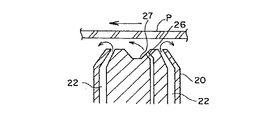
別の態様において、上述のような送気部材50を浮揚部材20に組み込んでよい。そのように、送気部材を有する浮揚部材の図9と同様の断面図を図10に模式的に示す。
浮揚部材20には、対象物体Pを浮揚させるための2つの送気口22に加えて、送気口22の間に斜め方向(右下から左上に向かう方向)に気体を吹き出すように開口し、対象物体の移動をコントロールする送気口26を有する。送気口26は、浮揚部材20の上端に形成された凹部27の側面で開口している。
尚、送気口26は、全体として柱状物の端面に設けた穴(例えば円形の穴)形態の開口部であってよく、あるいは、対象物体の移動方向に対して垂直かつ水平な方向に沿って、対象物体の下でその幅全体にわたって延在する長尺部材の頂部表面に設けた一連の複数の穴形態の開口部またはスリット形態の開口部であってよい。
【0071】
次に、本発明の加熱処理装置の加熱処理空間に用いることができる断熱構造を説明する。
図11に本発明の加熱処理装置の加熱処理空間の断面図(対象物体の移動方向に垂直な断面図)を模式的に示す。本発明の加熱処理装置の加熱処理空間10は、1つの態様では、通常の外壁材料で構成された筒状外壁60の内側全面に、高配向グラファイトシートからなる均熱シート62が貼設されている。高配向グラファイトシートとして、パナソニックグラファイトシート(松下電器産業株式会社製)を用いることができる。この高配向グラファイトシートは、例えば厚さが0.1mmで、無酸素状態における耐熱温度は3000℃以上で、熱伝導性率8.0W/cm・°K(面方向の値。面に垂直な方向は面方向の1/100)、引張強度が約200kg/cm2であり、柔軟であるので湾曲させたり、また、変形させることも可能である。筒状の外壁を形成する外壁材料としては、従来の加熱処理装置の加熱処理空間に一般的に使用されている材料を使用することができ、例えば、ステンレス、インコネル、セラミック材、石英ガラス等を使用できる。
均熱シート62の内側には、多数の断熱ブロック64が敷き詰めて配設される。断熱ブロック64により形成される空間の内側で、浮揚状態で対象物体Pが移送される。対象物体Pの下方には、浮揚部材20に設けた送気口から気体が吹き付けられ、それにより対象物体Pは浮揚し、また、浮揚部材20に設けた燃焼口24からの火炎fが対象物体Pを加熱する。
【0072】
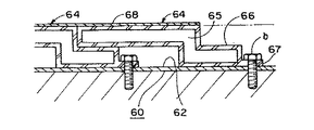
図12に断熱ブロック64の一例を斜視図にて模式的に示す。図示するように、断熱ブロック64は、全体としての平面形状(例えば図示した態様では上方から見た形状)がほぼ矩形状をなす。この断熱ブロックは、例えばガラス成形体であってよい。
図13には、図12の断熱ブロックを均熱シートを介して加熱処理空間の外壁60に貼り付けた状態を模式的に断面図にて示す。断熱ブロック64のその内部65は中空状態であり、高真空状態で封止されている。断熱ブロック64の対象物体に面する側の表面には赤外線反射膜68が形成されている。
【0073】
各断熱ブロック64は、第1ブロック部分70および第2ブロック部分66を有して成り、これらのブロック部分は、その縁部分において相互に重なり一体の断熱ブロック64を形成している。このような断熱ブロックを加熱処理空間内に並べて配置する場合、第2ブロック部分66上には、隣接する断熱ブロックの第1ブロック部分70の一部分が重なり、第2シート状部分はスペーサとしての機能を果たす。第2ブロック部分66の先端には小さな突出片67が設けられている。図13に示すように、断熱ブロック64を外壁60との間に均熱シート62を挟んで配置した後、突出片67にボルトbを挿通して外壁60に締結すれば、断熱ブロック64が外壁60に固定される。
なお、外壁60の内面に断熱ブロック64を敷き詰めた状態では、第2ブロック部分66、突出片67およびボルトbは第1ブロック部分70の裏面側に隠れ、加熱処理空間の内側露出面は、断熱ブロック64上の赤外線反射膜68だけによって規定されることになる。
【0074】
上述のような断熱構造を採用すれば、火炎fから放出される熱の一部は、直接に対象物体Pに吸収される。残りの熱(および場合により存在し得る対象物体Pから放出される熱)は、周りに配置された断熱ブロック64の赤外線反射膜68で反射されて、中に位置する対象物体Pを加熱することになる。その結果、熱エネルギーを有効に利用して、外部への熱エネルギーの放出を少なくできる。
真空空間65を有する断熱ブロック64は、外部への熱の放出を良好に阻止する。但し、断熱ブロック64あるいはブロック間の隙間を通過して外側に熱が漏れる場合がある。また、内部空間における火炎fや対象物体Pの配置によっては、断熱ブロック64により形成される内壁の一部分に大量の熱エネルギーが供給されるので、その部分の断熱ブロック64を外向きに通過する熱エネルギーが生じ、その結果、断熱ブロック64の外側に局部的な高熱個所が生じることがあり得る。
【0075】
しかしながら、図示したように、断熱ブロック64の外側に均熱シート62が配置されている場合、断熱ブロック64を通過した熱は、均熱シート62に吸収される。均熱シート62は吸収した熱を全面に均等に分配することで、局部的に高熱になり得たであろう外壁60の内面の箇所の温度を下げる。外壁60を通過して外部に放出さる熱エネルギーの損失量は、外壁60の内側と外側との温度差に比例するので、均熱シート62によって、外壁60の一部分の内側が高温になることが防止され、そのような箇所から外壁60を通過して外部に放出される熱エネルギーが減る。また、均熱シート62で外壁60の内面における温度分布が平均化されれば、断熱ブロック64の内側空間における温度分布も平均化され易くなり、対象物体Pに対する加熱も均等化される。
【0076】
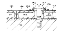
図14に、別の態様の断熱ブロックの形態を用いた断熱構造を、図13と同様に、模式的に示す。図示した、断熱ブロック164は、全体としてほぼ矩形の板状をなし、外壁60の内側に均熱シート62を介して敷き詰められる。断熱ブロック164は、その内部に高真空空間165を有する。断熱ブロック164の内側表面には赤外線反射膜168が形成されている。断熱ブロック164には取付孔166が貫通形成されている。取付孔166には取付ネジ167が挿通され、取付ネジ167を外壁60にネジ込み固定することで、断熱ブロック164が外壁60に固定される。取付ネジ167は、円盤状のスペーサ169を介して断熱ブロック164に当接する。スペーサ169は断熱性に優れたセラミック等の材料で形成されている。この形態では、円盤状のスペーサ169が、取付孔166の開口を塞ぐことで、取付孔166を通じて熱が放出されるのを阻止することができる。
【0077】
図15に、本発明の加熱処理装置の別の態様の加熱処理空間の断面図(対象物体の移動方向に垂直な断面図)を模式的に示す。但し、図示した態様では、加熱処理空間の周辺部を規定する筒状外壁および断熱ブロックにより形成される壁を図示していない。
図示した態様では、浮揚部材20で浮揚される対象物体Pを囲むように、何れも筒状をなす、内側均熱シート110および外側均熱シート112が配置される、即ち、二重層構造で均熱シートが対象物体の周囲に配置されている。外側均熱シート112の外側には外壁60(図示せず)が存在する。均熱シート110と112との間には、上下2個所に電気ヒータ114がそれぞれ配置されている。図15に示す態様では、電気ヒータ114により発生する熱が、均熱シート110および112によって無駄なく効率的に全体に伝えられる。即ち、均熱シート110および112は電気ヒータ114で発生した熱を全周へと迅速に伝えるとともに、均熱シート110の内面から放射される熱が均一化されて、対象物体Pに伝えられて対象物体Pを加熱する。その結果、対象物体Pは全体を均等に加熱されることになる。
【0078】
図16に、本発明の加熱処理装置の別の態様の加熱処理空間の断面図(対象物体の移動方向に垂直な断面図)を模式的に示す。但し、図示した態様では、加熱処理空間の周辺部を規定する筒状外壁および断熱ブロックにより形成される壁を図示していない。
図示する態様では、均熱シートとマッフル構造とを組み合わせる。浮揚部材20で浮揚される対象物体Pを囲む位置に、筒状に構成されたSUS金属等からなるマッフル構造部120が配置される。マッフル構造部120の外側には断熱材からなるスペーサ124を介して均熱シート122が配置されている。均熱シート122の外側には外壁60が配置されるが、図示を省略している。均熱シート122の外側に隣接して下方に電気ヒータ126が配置されている。
電気ヒータ126の熱は、均熱シート122に伝わり、均熱シート122で全周に伝達される。その後、均熱シート122から輻射熱によって、熱がマッフル構造部120に伝達され、マッフル構造部120が輻射熱によってその内部の空間に配置された対象物体Pを加熱する。尚、本明細書において、マッフル構造部とは、電気ヒータのような加熱手段と対象物体Pの加熱処理空間とを分離する隔壁構造を意味する。
図示した態様では、均熱シート122がマッフル構造部120に対してスペーサ124以外では実質的に接触していないので、均熱シート122を加熱したときに、熱容量が比較的小さい均熱シート122のみに熱が伝わって迅速に昇温する。昇温した均熱シート122からの輻射熱がマッフル構造部120に伝わり、マッフル構造部が対象物体Pを加熱するので、対象物体Pは全周から迅速かつ均等に加熱されることになる。
【0079】
図15および図16を参照して説明した態様では、加熱処理すべき対象物体の少なくとも一部分と空間部を隔てて重なるように電気ヒーターのような加熱手段を配置しているが、加熱手段の配置は、対象物体から離れていてもよい。
そのような態様を図17に模式的に示す。この態様では、対象物体Pを包囲する均熱シート130が対象物体とは重ならないフラップ部132を有し、この部分を加熱する。
例えば、加熱処理空間10(図示せず)の内部に、均熱シート130が筒状に巻回された状態で対象物体Pの周囲の空間を包囲するようにし(例えば、図示するように、均熱シート130は対象物体Pの周囲の空間を2重に囲むように配置し)、均熱シート130の端部132が、対象物体の周囲の空間から離れて外方に引き出されている。
【0080】
この態様では、均熱シート130のフラップ部132に隣接する下方位置にガスバーナ134が配置されている。ガスバーナ134は火炎fを発生して上方のフラップ部132を加熱する。フラップ部132に供給された熱は均熱シート130の全面に迅速に伝達され、均熱シート130からの輻射熱で内部空間を加熱する。その結果、均熱シート130の内部空間を移送される対象物体Pを全周から均等に加熱することができる。
ガスバーナ134は、支持アーム135を介して駆動軸136に支持されている。駆動軸136は矢印で示すように、旋回および昇降が可能になっている。
駆動軸136を旋回すれば、ガスバーナ134で加熱する延長端132の位置が変更でき、均熱シート130の内部空間に配置された対象物体Pへの伝熱状態が変わる。例えば、対象物体Pの移動に伴ってガスバーナ134の加熱位置を変えて、対象物体Pの特定位置をより強く加熱することが可能になる。
また、駆動軸136を昇降させれば、ガスバーナ134とフラップ部132との距離が変わり、ガスバーナ134からフラップ部132に伝わる熱エネルギーの強さが調節でき、対象物体Pの加熱処理温度調節が容易になる。尚、ガスバーナ134を筒状の均熱シート130の軸方向に沿って平行移動させる機構を備えておいたり、加熱手段としてガスバーナ134以外の手段も使用でき、例えば電気ヒータを用いることも可能である。
【0081】
本発明の加熱処理装置において、加熱処理空間10を規定する断熱壁の構造は、図11〜14を参照して説明したが、図18に断面図にて模式的に示す構造であってもよい。
図18に示す態様では、外壁60の内側に、断熱材層142、均熱シート140、断熱材層142、均熱シート140およびマッフル構造部144が順次配置されている。マッフル構造部144の内側の空間を対象物体Pが移送される。対象物体Pの加熱手段も別途設けられる。図示した態様では、均熱シート140と断熱材層142の組み合わせが2対配置されているが、この組み合わせが1対であっても、3対以上であってもよい。
この態様では、マッフル構造部144の内部空間で発生した熱が、マッフル構造部144を経て均熱シート140に伝わると、熱が迅速に全周に伝達されて全周の温度が均一化される。均熱シート140の外側に配置される断熱材層142によって外部に熱が逃げるのを阻止する。
【0082】
一般に、加熱処理空間の断熱壁のうち一部が局部的に高熱になると、その部分では断熱壁が存在していても、内外の温度差が大きいために、断熱壁を通過して外部に熱が放出され易くなる。しかし、上述の構造の断熱壁では、均熱シート140が局部的な高熱個所の熱を全周に均等に分配することになるので、局部的に高温になる部分が生じ難い。局部的な高温が生じなければ、断熱材層142等の断熱壁を通過して外部に放出される熱エネルギーは少なくなる。その結果、加熱処理室の全体として、外部への熱の放出を削減することができ、熱エネルギーの効率的利用が可能になる。
【0083】
図19に、本発明の加熱処理方法に用いる加熱処理空間10の別の態様の一部分を、図3と同様に、その中の様子が理解できるように斜視図にて模式的に示す。この態様は、特に熱処理ゾーンに使用するのが特に好ましい。尚、図20に図19の態様の加熱処理空間の断面図(対象物体の移送方向であって、対象物体に垂直な断面図)を模式的に示している。
図示した態様の断熱壁構造は、図3の場合と同様であってよい。図示した態様においても、浮揚部材20、吸引停止手段30等からなる、対象物体の浮揚・移動機構が設けられているが、簡単のため、図示を省略している。昇温ゾーンのように多量の熱を加える必要がある場合には、浮揚部材20には、図4に示すような燃焼口24を設けてもよいが、熱処理ゾーンのようにそれほど多量の熱を加える必要がない場合には、燃焼口24を省略してよく、図9または図10に示すような浮揚部材20の構造を採用してよい。
【0084】
図20にも示すように、対象物体Pが移送される移動経路の下方に、平面U字形をなす電気ヒータ80が設けられ、電気ヒータ80の下方には均熱シート100が配置され、さらにその下方に熱媒体流通管90が設けられている。
熱媒体流通管90は、外管96と孔付き内管98との二重構造になっている。図19に示すように、内管98は加熱処理室10の壁面を貫通して外部に引き出され、着火部92に接続されている。着火部92は燃料ガス導管93および排気導管94に接続されている。燃料ガス導管93から着火部92に供給された燃料ガス(または可燃性ガス)は、着火部92で着火されて燃焼し、燃焼ガスが内管98に供給される。燃焼ガスは内管98の外周の孔を通じて外管96に入る。外管96は着火部92を介して排気導管94に連結されており、外管96を通過した燃焼ガスは排気導管94から回収される。燃料ガスが内管98および外管96を流通している間に、外管96の表面から外周に向かって熱が放出される。
【0085】
図20に示すように、熱媒体流通管90から放出された熱は、均熱シート100に吸収されて、均熱シート100の全体に均等に拡がり、均熱シート100から上方に輻射され、上方の対象物体Pを加熱する。均熱シート100の上方に配置された電熱ヒータ80からも熱が供給されて対象物体Pを加熱する。
図示した態様では、熱媒体流通管90の位置から局部的に大量の熱エネルギーが放出されても、その熱エネルギーが均熱シート100で均熱化されてから対象物体Pに供給されるので、対象物体Pを均等に加熱することができる。また、熱媒体流通管90とは異なる位置に配置された電気ヒータ80からも熱エネルギーを供給するので、電気ヒータ80によっても均熱化が図られる。
【0086】
本発明の加熱処理方法の1つの好ましい態様では、熱媒体流通管90および電気ヒータ80の2種類の加熱手段を組み合わせることにより、対象物体Pの加熱処理温度をより精密にコントロールする。図21は、対象物体Pを目標温度T0まで加熱する際の時間tと加熱処理空間の到達温度Tとの関係の一例を示している。到達温度Tは、熱媒体流通管90により加えられる熱量(領域Iで表される)と、電気ヒータ80により加えられる熱量(領域IIで表される)とが足し合わされた結果である。領域Iと領域IIとの間の境界の折れ線は、熱媒体流通管90を単独で使用した場合に達成される温度上昇である。
熱媒体流通管90により加熱する場合の温度調節は、燃料ガスの供給量を調節することにより行うが、発生する熱量が多量であるため、燃料ガスの供給量を変化させても、燃焼ガスから放出される熱エネルギーの量、従って、加熱温度が迅速に変化せず、ある程度の時間のずれが生じる。そのため、熱媒体流通管90による加熱温度が大きく変動することは避けられない。電熱ヒータ80は、熱媒体流通管90に比べて発生できる熱エネルギーの量は少ないが、供給電力を変化させれば直ちに発生する熱エネルギーの量が変わる。
そこで、熱媒体流通管90による温度上昇を、目標温度T0よりも少し低めに設定しておき、その温度上昇と目標温度T0との差を、電熱ヒータ80による加熱によって補償するようにすれば、実際の到達温度Tを、目標温度T0に迅速に到達させ、その後も経時的に到達温度Tを目標温度T0に一致させておくことが容易である。その結果、対象物体Pに対する加熱温度を正確に制御して、品質性能の高い加熱処理を実現することができる。
【0087】
先に説明したように、本発明の加熱処理装置は、加熱処理空間の後に降温ゾーンを有してよい。この降温ゾーンZを熱処理ゾーンYの一部分と共に断面図にて図22に模式的に示す。降温ゾーンにおいては、対象物体Pにその温度より低い温度の気体を吹き付けて対象物体の温度を下げる。
図示した態様では、熱処理ゾーンYと降温ゾーンZとの間には、押出部170が配置され、押出部170に備えた押出アーム172が水平方向に移動することで、熱処理ゾーンYを搬送されてきた対象物体Pを、降温ゾーンZに送り込む。
【0088】
降温ゾーンZには、送り込まれた対象物体Pを、空間を隔てて積み重ねた状態で上から下に降下させるコンベア180が設けられている。対象物体Pは面方向に一定の間隔をあけて並べられた状態で徐々に下方に移動していく。
下方に移動する対象物体Pの側方には、上方から下方に向かって、水平方向に一連の複数の送風ノズル(または送風スリット)を有する送風手段150が設けられている。各送風手段150は背後のヒータ加熱部152を経て送風機156に連結されている。
【0089】
図示した態様では、送風機156では、昇温ゾーンXおよび/または熱処理ゾーンYで加熱に利用されて排気された気体を回収する排気管158から気体が送り込まれ、この気体を直接、あるいはこの気体と熱交換した気体を、必要に応じてヒータ加熱部152により所定温度まで加熱して得られる気体が送風手段150から対象物体Pに送り出される。より低い温度の気体が送風手段150から吹き出すのが望ましい場合には、ヒータ加熱部152を省略してもよく、場合により、より低温の別の気体を混合してもよい。
【0090】
図示した態様では、上下に並んだ複数のヒータ加熱部152は、降温に使用する気体の温度が(下方に向かって)段階的に下がるように操作される。例えば、図22の上下3個所の送風手段150では、上から350℃、300℃、200℃の冷却風がそれぞれ吹き出す。
対象物体Pの通過経路を挟んで各送風手段150と対向する位置には、排気口を有する排気手段153が配置され、排気手段153は排気管159に連結されている。
【0091】
降温ゾーンZを降下する対象物体Pは、数百℃程度に加熱されていることが多いので、上部の送風手段150から吹き出す例えば350℃の冷却気体が吹きつけられることで冷却降温される。対象物体Pが降下移動するにつれて、段階的に低い温度の冷却風が吹きつけられるので、対象物体Pの温度は順次降下する。降温ゾーンZの下端まで移動した対象物体Pは例えば150℃程度まで冷却されており、その後、水平方向に搬送され、加熱処理装置1の外へ出て回収コンベア184に回収される。加熱処理装置を出た対象物体Pは、その後は自然放冷で常温まで冷却される。図22に示す態様では、降温ゾーンZは、対象物体Pの面積よりも少し広い程度の設置スペースしか取らずに、設置することができる。対象物体Pの表裏両面に沿って冷却風が通過することで対象物体Pの全体を効率的に冷却することができる。
加熱処理を終えた対象物体Pを急速に冷却すると、その途中で割れや歪みが生じるという問題があった。これは、対象物体Pを冷却する際に、対象物体の場所によって冷却の進み方が違って温度差が生じ、この温度差により、冷却収縮挙動が一様ではなく、それに伴う応力で歪みや割れが生じると考えられる。
【0092】
しかし、上述の態様では、各段階毎の冷却風の温度を低くして対象物体と冷却風との温度差を大きくして、高温から低温まで急激に冷却させたとしても、それぞれの段階では、一定温度の冷却風が対象物体Pの主表面に沿って全体に効率的に吹き付けられ、対象物体Pの全体を冷却風の温度で決まる一定の温度まで均一かつ迅速に冷却できる。そのため、対象物体Pに対して場所による温度のバラツキすなわち温度差が生じ難い。具体的には、対象物体Pの場所による温度差を数℃以内に抑えることができる。その結果、割れや歪みの問題が改善される。
例えば、1m平方の大型ガラス基板を冷却降温させる場合、通常の徐冷方法に比べて、約1/2以下の時間でも割れや歪みを生じることなく急冷させることができる。また、上述の態様では、降温のために使用する気体を加熱する熱源として、加熱処理空間10で発生する排気が有する顕熱を回収して利用するので、熱エネルギーが有効に利用される。
【0093】
本発明の加熱処理方法において、浮揚させた対象物体を移動させる方法の別の態様を図23に示す。ここでは、対象物体の移動方向に沿った対象物体に垂直な断面図にて模式的に示す。図示した態様では、図9に示すのと同様の構造の浮揚部材20を用いる。浮揚部材20は、対象物体Pに対して実質的に垂直に気体を吹き出す。
図23(a)に示す状態では、対象物体Pは、浮揚部材20から上方に吹き出す空気で浮揚し、水平な状態で一定の位置に止まっている。次に、図21(b)に示すように、対象物体Pの後方縁の下方の近くに配置された浮揚部材20xから吹き出す気体の圧力を上げる。例えば、他の浮揚部材20に比べて120%の圧力で気体を吹き出す。そうすると、大きい圧力で気体を吹き付けられた対象物体Pの後方縁が図示するように上方に持ち上げられ、対象物体Pが角度θで傾斜する。
対象物体Pが傾斜すると、対象物体Pの下面に加わる気体の圧力で、対象物体Pを傾斜の低いほうに向かって水平方向に前進させる作用が生じ、対象物体は左向きに移動し始める。尚、力学的には前進力F(=mg・sinθ、ここで、mは対象物体の質量、gは重力の加速度である)が発生する。従って、対象物体Pの下面に配置される複数の浮揚部材20から上方に吹き出す気体の圧力を、場所によって違えるだけで、対象物体Pを水平方向に移動させることができる。
【0094】
図23(c)に示すように、対象物体Pが水平方向に移動し始めると、浮揚状態であれば移動に対する抵抗はほとんどないので、慣性の作用で、そのまま水平方向に移動し続ける。先に吹き出し圧力を強くした浮揚部材20xでは、通常の吹き出し圧力に戻せばよい。従って、対象物体Pが水平移動を開始するまでの短い時間だけ、対象物体Pの片端側の浮揚部材20で圧力を強くすればよいのである。
また、水平移動する対象物体Pに対して、対象物体の後方縁の下方に位置する浮揚部材20の圧力を対象物体Pの後方縁が通過する間だけ吹き出し圧力を順次大きくすれば、空気抵抗等の対象物体Pに加わる抵抗で速度が落ちない程度に前進力を補うことができる。この時、加える前進力を大きくすれば、対象物体Pを順次加速させることもできる。対象物体Pの通過位置および時間等をセンサ等で検知して、検知された対象物体Pの位置に合わせて、各浮揚部材20の吹き出し圧力を制御すればよい。
【0095】
上述のような移動機構を利用すれば、対象物体Pの速度や移動方向の変更、あるいは、移動停止の制御も可能である。例えば、図23(b)で、浮揚部材20xの吹き出し圧力を調整すれば、対象物体Pの傾きθが変わり、水平方向への前進力Fの大きさ、即ち、移動速度が変わる。図23(b)で、対象物体Pの反対側の縁(左端)近くの浮揚部材20で吹き出しを強くすれば、対象物体Pは反対側に傾斜して反対(右)方向に水平移動する。水平移動している対象物体Pに対して、対象物体Pの先頭側の下方に位置する浮揚部材20で吹き出し力を大きくして、対象物体Pの先頭側が持ち上げられるように傾斜させれば、前記した力Fは移動方向の逆方向に作用して制動力となり、停止させることもできる。
【0096】
【発明の効果】
本発明にかかる加熱処理方法および装置によれば、対象物体に気体を吹きつけて浮揚させた状態で対象物体を搬送することにより、従来のコンベア装置のように、加熱処理室の内外を出入りする機械構造が必要なくなり、加熱処理室内の熱エネルギーを無駄に放出することがない。その結果、加熱処理装置から外部に漏れる熱エネルギーを低減して、熱エネルギーの利用効率を向上させることができる。
また、従来の加熱処理装置において加熱処理空間内に存在していた種々の機械的機構を省略して、対象物体を浮揚させて、それを移動させる上述の機構を設けるだけでよいので、加熱処理空間内に存在する機構の数は全体として大幅に減少し、従って、種々の機構の存在によって生じる発塵の問題を改善できる。
【図面の簡単な説明】
【図1】 図1は、本発明の加熱処理方法に使用する加熱処理装置を斜視図にて模式的に示す。
【図2】 図2は、本発明の加熱処理における温度条件の一例を示すグラフである。
【図3】 図3は、本発明の加熱処理方法に用いる加熱処理空間の一部分をその中の様子が理解できるように斜視図にて模式的に示す。
【図4】 図4は、浮揚部材20の断面図を模式的に示す。
【図5】 図5は、対象物体を移動する様子を側方から見た場合の対象物体の移送経路の様子を示している。
【図6】 図6は、本発明の加熱処理方法において浮揚した対象物体を機械的な力を用いて移動させる機構を模式的に示す。
【図7】 図7は、プッシュ方式で対象物体を移動させる機構を模式的に示す。
【図8】 図8は、吸引停止手段30の断面図を模式的に示す。
【図9】 図9は、対象物体の移動をコントロールする送気部材の断面図を模式的に示す。
【図10】 図10は、送気部材を有する浮揚部材の図9と同様の断面図を模式的に示す。
【図11】 図11は、本発明の加熱処理装置の加熱処理空間の断面図を模式的に示す。
【図12】 図12は、断熱ブロック64の一例を斜視図にて模式的に示す。
【図13】 図13は、図12の断熱ブロックを均熱シートを介して加熱処理空間の外壁に貼り付けた状態を模式的に断面図にて示す。
【図14】 図14は、別の態様の断熱ブロックの形態を用いた断熱構造を模式的に示す。
【図15】 図15は、本発明の加熱処理装置の別の態様の加熱処理空間の断面図を模式的に示す。
【図16】 図16は、本発明の加熱処理装置の別の態様の加熱処理空間の断面図を模式的に示す。
【図17】 図17は、均熱シートを使用する加熱機構の別の態様を斜視図にて模式的に示す。
【図18】 図18は、本発明の加熱処理装置において加熱処理空間を規定する断熱壁の構造の別の態様を模式的に示す。
【図19】 図19は、本発明の加熱処理方法に用いる加熱処理空間の別の態様の一部分を、図3と同様に、その中の様子が理解できるように斜視図にて模式的に示す。
【図20】 図20は、図19の態様の加熱処理空間の断面図を模式的に示す。
【図21】 図21は、対象物体Pを目標温度T0まで加熱する際の時間と到達温度Tとの関係の一例を示している。
【図22】 図22は、降温ゾーンZを熱処理ゾーンYの一部分と共に断面図にて模式的に示す。
【図23】 図23は、本発明の加熱処理方法において、浮揚させた対象物体を移動させる方法の別の態様を模式的に示す。
【符号の説明】
10…加熱処理装置、14…開口部、20…浮揚部材、24…燃焼口、27…排気部材、30…吸引停止部材、31…本体部、32…吸引気体路、33…加圧気体路、40…摺動部材、46,47…旋回軸、48…プッシュアーム、49…ストップアーム、50…送気部材、60…外壁、62…均熱シート、64…断熱ブロック、80…電気ヒータ、90…熱媒体流通管、100…均熱シート、114…電気ヒータ、126…電気ヒータ、130…均熱シート、132…フラップ部、134…ガスバーナ、140…均熱シート、144…マッフル構造部、150…送風手段、152…ヒータ加熱部、153…排気手段、156…送風機、158…排気管、164…断熱ブロック、170…押出部、172…押出アーム、180…コンベア、200…駆動手段、202…移動経路、204…当接要素、210…支持要素、f…火炎、P…対象物体、X…昇温ゾーン、Y…熱処理ゾーン、Z…降温ゾーン。[0001]
BACKGROUND OF THE INVENTION
The present invention relates to a heat treatment method and apparatus, and more particularly to a method and apparatus for heat-treating raw materials, intermediate products or final products in the manufacture or treatment of various products.
[0002]
[Prior art]
Various heat treatments are used in the production of various products. Specifically, many actions achieved by heat treatment such as drying, dehydration, firing, reaction acceleration, surface modification, and the like are known. In order to improve the efficiency of the heat treatment, the heat treatment is performed by passing the object to be heat-treated by a conveyor or the like through a heating space such as a dome shape or a tunnel shape.
[0003]
An apparatus that performs such heat treatment includes a temperature rising zone that heats the target object to a temperature at which heat treatment is to be started and a target object that has been heated along the moving (or transfer) direction of the target object. Consists of heat treatment zones that are exposed to a predetermined thermal environment (for example, maintaining a raised temperature for a given time or subjecting the heated temperature to a given temperature change), and the boundary between these zones is not clear In some cases. In this specification, the heat treatment is used as including both the temperature rise and the heat treatment. Furthermore, an apparatus for performing the heat treatment as described above generally has a cooling zone after the heat treatment zone that lowers the target object to a predetermined temperature after the heat treatment. The target object passes through these zones in order.
[0004]
[Problems to be solved by the invention]
However, in the above heat treatment method, the proportion of heat energy consumed by the heat treatment itself of the target object is small in the heat energy supplied to the heat treatment apparatus, and most of the supplied heat energy is wasted. However, there is a problem that the utilization efficiency of heat energy is low, which causes high cost of heat treatment.
[0005]
In the conventional heat treatment method, the reason why the utilization efficiency of heat energy is low may be, for example, the following reasons:
In the tunnel-like heat treatment space where the conveyor that moves the target object enters and exits, the entrance / exit is always open, so a part of the thermal energy supplied to the heating device is released from the entrance / exit. It is said that the release of thermal energy from the entrance / exit is about 30% of the thermal energy supplied to the heating device.
In the heat treatment space, since the conveyor is heated in addition to the target object, a large amount of heat energy is required to heat the moving mechanism such as the conveyor. A moving mechanism such as a conveyor is complex and has a large heat capacity, and a large amount of heat energy is required to heat such a conveyor. Since the conveyor moves the target object from before the heating to after the heating, when the conveyor leaves the heating space, the heat energy supplied to the conveyor in the heating furnace is released to the outside and is wasted. Each time the conveyor circulates in and out of the heat treatment space, a large amount of heat energy is supplied to the conveyor and is discharged to the outside without using the supplied heat energy. It is said that the carry-out of heat energy by such a conveyor is about 20% of the supplied heat energy.
[0006]
Furthermore, in the conventional heat treatment apparatus, the amount of heat energy released to the outside from the walls constituting the heat treatment space is large, and about 45% of the supplied heat energy is released from the walls of the heat treatment space. It is said.
As a result, in the conventional heat treatment method, it is said that only 5% or less of the total heat energy that can be actually used for the heat treatment of the target object is supplied.
Therefore, an object of the present invention is to eliminate the problems of the conventional heat treatment method and to improve the utilization efficiency of heat energy.
[0007]
[Means for Solving the Problems]
The present invention provides a method for heat-treating a target object, the method being performed in a predetermined manner in a state where the target object is levitated by blowing gas toward the target object from below the target object in the heat-treatment space. An object is heated.
[0008]
In the present invention, the heat treatment may be any treatment in which heat is applied to the target object. By this heat treatment, at least one characteristic of the target object (for example, moisture retention, electrical resistance, transmittance, formed film) Thickness or its uniformity, stress, etc.) changes as predetermined. For example, the heating process includes a process of raising the temperature of the target object to a predetermined temperature in a predetermined time, a process of maintaining the temperature of the target object at a predetermined temperature for a predetermined time, and / or a process of exposing the target object to a predetermined temperature change condition, etc. Including. The heat treatment is a process of applying heat as described above, but it is not always necessary to add heat during the heat treatment period, and there may be times when heat is not applied. The heat treatment temperature may be lowered.
[0009]
Further, the target object is a target to be heat-treated. The target object may have any form, and thus may have a complicated form. In general, the target object as a whole may have a plate, sheet, or film-like form (which may be a continuous form such as a long belt or a form divided into a fixed length). Preferably, the dimension (or dimension) in the horizontal direction is considerably larger than the dimension (ie, thickness) in the direction perpendicular to the horizontal dimension (or dimension). In the present specification, the horizontal direction means a direction in which a main surface defining a sheet-like target object spreads. The target object preferably has a sheet-like form as a whole even if there are uneven portions on one or both of the main surfaces.
[0010]
The material which comprises a target object is not specifically limited, For example, a target object may be comprised from ceramic, glass, a metal, resin, another structural material, or any combination thereof. In one aspect of the present invention, the target object may be formed by combining at least two target objects as described above. In this case, the target object formed by the combination may be in a sheet form. It may be a more complicated form.
Specifically, the heat treatment includes, for example, drying, dehydration, firing, reaction, reaction acceleration, surface modification, sintering, thermosetting, heat melting, adhesion, and the like. Target objects in such processing include, for example, a semiconductor substrate, a PDP (plasma display panel) substrate, a solar cell substrate, a liquid crystal substrate, a CRT (TV CRT), and the like.
[0011]
In the method of the present invention, levitation of the target object by blowing gas on the target object means that the target object is in a state of floating in the gas. The force (gas dynamic pressure or static pressure) that pushes the target object upward, which is generated by blowing the gas toward the target object from below and colliding with the target object, is the gravity acting on the target object. The target object is levitated in the surrounding gas by being balanced. Normally, the target object is lifted by ejecting gas from the air supply port perpendicularly to the lower surface (bottom surface) of the target object from below the target object. In addition to the lower surface of the target object, it is also possible to adjust the posture of the target object by blowing gas toward the upper surface and / or side surface of the target object.
[0012]
Furthermore, when the direction in which the gas hits the lower surface of the target object is not perpendicular to the lower surface but oblique, a force that can be divided into a horizontal component force and a vertical component force acts on the target object by the gas. The horizontal component force is determined by moving the target object in the direction of the component force when the target object is stopped, and depending on the direction of the component force when the target object has already moved. It acts to accelerate or decelerate the moving speed of the target object. For example, when a gas is blown onto a moving target object so as to apply a component force in a direction opposite to the moving direction, the movement of the target object can be decelerated or stopped. The vertical component force is used to levitate the target object.
[0013]
The gas is blown onto the target object by supplying the gas toward the target object through an opening serving as an air supply port. Usually, in the heat treatment space, a plurality of, preferably a large number of air supply ports are provided below the place where the target object is located and the place where the target object is to be located (that is, on the movement path of the target object). You may implement so that a gas may hit against an object from the same direction or from different directions. In such a case, when the resultant force acting to push the target object with the gas supplied through the air supply port has a horizontal component force, the target object moves in the direction of the component force.
[0014]
Specifically, an air supply port may be provided in the heat treatment space so as to blow gas vertically and upwardly at a plurality of locations on the lower surface of the target object. The gas supply port may be provided in the heat treatment space so that the gas is blown vertically and upward, and the gas is blown obliquely and upward to another portion. How to blow the gas (and thus how to provide the air inlet) depends on how the object is levitated and how it moves as needed. Then, it can be easily selected based on the disclosure of the present specification.
[0015]
Therefore, in the heat treatment method of the present invention, the target object may move as described above in the floating state during the heat treatment, or may stop in the floating state. Furthermore, stop and movement may be combined in the levitated state. For example, the heat treatment method may include a sequence in which the heat treatment is stopped in the levitation state, the heat treatment is performed, and then the heat treatment is further performed while moving in the levitation state, or vice versa. Whether the levitated target object is to be stopped or moved can be selected according to the type of heat treatment required for the target object.
[0016]
In the present invention, the movement and the stop relate to the presence or absence of movement of a substantial distance along the horizontal direction of the target object. Stopping means a state in which the target object does not move at least in the horizontal direction (thus, it may or may not move in the vertical direction). The movement means a state in which the target object moves at least in the horizontal direction (thus, it may or may not move in the vertical direction).
[0017]
In the case where the predetermined heat treatment is performed for a long time, it is preferable that the target object is levitated in a stopped state at a predetermined position and then the heat treatment is performed, and then the target object is moved, and the heat treatment space can be reduced. In the case of short-time heat treatment, it is preferable to carry out the heat treatment while continuously moving (preferably at a constant speed) in a floating state in the heat treatment space, and the treatment efficiency is increased. It is also possible to combine these two methods, that is, heat treatment in a stopped state and heat treatment in a moving state.
[0018]
In another method, the target object is floated by the gas in the heating space and moved by the gas, and the heat treatment itself is mechanically supported in a state where the target object is not lifted (for example, in the vertical direction). State). In one preferable aspect, the target object may be moved by mechanically applying force to the target object while the target object is levitated by gas in the heating space. In this case, the heat treatment is performed on the target object. It may be performed during movement and stoppage, or at any time.
[0019]
The gas used for levitation of the target object may be any gas as long as it does not adversely affect the heat treatment of the target object or accelerates the heating. In general, air, a gas for forming a heated atmosphere, for example, an inert gas such as nitrogen, a reactive gas, or a mixture thereof can be used. These gases are preferably heated appropriately according to the heat treatment temperature. In that case, both the heat treatment and the gas levitation can be carried out simultaneously. Combustion gas, which is a high-temperature gas, can also be used when it does not adversely affect the target object.
[0020]
The gas is jetted toward the target object through the air supply port as described above, and the gas supply port is capable of supplying gas so that a predetermined pressure can be applied to the target object in a predetermined direction. There is no particular limitation. The air supply port may be in the form of, for example, a nozzle, a slit, or a mesh, and the cross-sectional shape is not particularly limited, and may be, for example, a circle, an ellipse, or a rectangle. Usually, a plurality, preferably a large number of air supply ports are provided along a path in the heat treatment space that moves while the target object is levitated, so that the target object can pass through the heat treatment space in a levitated state. ing.
[0021]
In general, air supply ports are provided in a movement path of a large number of target objects in a row and / or a column (that is, in a direction along the movement path and / or in a direction perpendicular to the movement path). For example, the air supply ports may be provided in a lattice shape. The number of air supply ports and their arrangement depend on the heat treatment space, especially the path (length, width, etc.) through which the target object passes, and the weight (per unit bottom area), depending on the target object to be processed. ) And width, height to be levitated, and the like. Note that the height to be levitated (that is, the distance between the target object and the air supply port) may be any height as long as the target object can move smoothly, and is generally about 0.1 to 20 mm. In consideration of cost reduction associated with consumption of the levitation gas and improvement of the reliability of the conveying process due to thermal deformation of the target object, it may normally be about 0.5 to 3 mm.
[0022]
As described above, when using a method in which a target object is levitated by gas (gas levitation method), it is only necessary to substantially arrange an air supply port and a conduit leading to it in the heat treatment space. Mechanisms (eg, pumps, valves, control systems, etc.) can be placed outside the heat treatment space, thus making the equipment in the heat treatment chamber very simple. As a result, failures associated with the heat treatment apparatus are reduced and maintenance is facilitated. In other words, the use of the gas levitation method has an advantage that it is not necessary to arrange a complicated mechanical operation mechanism in the high temperature heat treatment space.
In addition, as described above, levitation and movement of a target object using gas is disclosed in, for example, Japanese Patent Application Laid-Open Nos. 61-267394, 2-76242, and 5-29238. The disclosures of these patent documents are hereby incorporated by reference.
[0023]
In one preferred aspect of the present invention, as described above, the movement of the levitated target object is performed using mechanical means (or force) instead of gas blowing. When the heat treatment temperature increases, the density of the gas decreases, and if it is attempted to move the object in addition to levitation, it may be necessary to install a means for supplying a very large amount of gas. is there. In such a case, only the levitation of the target object is performed with gas, and the horizontal movement is performed using mechanical force.
[0024]
For example, when a mechanical force is momentarily applied to the levitation target object in the direction in which the target object is moved (for example, simply pressed), the target object tends to move in the direction of the applied force. At that time, when gas is ejected one after another from the air supply port that exists along the path along which the target object moves, toward the moving target object, the gas sequentially supports the target object. The target object only floats in contact with the gas, the frictional force between the target object and the gas is small, and the gas blown from the bottom acts as a kind of bearing on the lower side of the target object, The target object can move at least some distance depending on the conditions at that time, with substantially only the first pushing force. Usually, the speed of the moving target object gradually decreases and finally stops. In order to stop the moving target object on the way, for example, the target object can be collided with an obstacle existing on an extension line in the moving direction, and the kinetic energy of the target object can be absorbed by the obstacle.
[0025]
Note that the moving speed and / or moving distance can be changed by changing the magnitude of the pressing force. Thus, the structure and operation of the means used for pushing and stopping the target object are relatively simple (for example, a simple structure may be used), and the acting force may be small.
[0026]
Alternatively, at least one abutment element (or stopper element) that moves in the heat treatment space in the same direction as the predetermined direction in which the target object should be moved is provided in the heat treatment space, and the moving abutment element floats. A part of the target object is contacted and restrained, and as a result, the contact element moves the target object by continuing to push the target object in a predetermined direction. Since the target object is constrained by the contact element, the movement of the target object can be stopped by stopping the movement of the contact element. Further, by changing the moving speed of the contact element, the moving speed of the target object in the heat treatment space can be controlled. Such an abutment element is provided in the driving means that moves on at least one side of the movement path of the target object in the heat treatment space, and preferably on both sides of the movement path. It is preferably fastened to a continuous drive means such as a moving chain or belt, and the contact means moves / stops in response to operation / stop of such drive means, so that the target object is Move / stop.
[0027]
In yet another aspect, when processing a target object in succession, a plurality of support elements (for example, carrier trays) arranged adjacent to each other in the heat treatment space and capable of being levitated by gas are prepared. A target object is arranged on each of the support elements, the first support element is arranged at the entrance of the heat treatment space, and then the second support element is brought into contact with the first support element and a force is applied to the second support element. The force is transmitted to the adjacent first support element to move the first support element and push it into the heat treatment space, and at the same time, the second support element is disposed at the heat treatment space inlet. Next, similarly to the above, the second support element is disposed at the inlet of the heat treatment space and brought into contact with the second support element, and the third support element is disposed at the inlet of the heat treatment space, so that the preceding second The support element and the first support element already in the heat treatment space are further advanced in the direction of movement. By repeating such an operation, the preceding support element is pushed by the subsequent support element to move in the heat treatment space. In this case, the support element is in a floating state by the gas blown from below in the heat treatment space. This method can be referred to as a plug flow method (or tocorotene method (extrusion method) or push method), in which a subsequent support element mechanically pushes the preceding support element. In this method, the support element having the target object moves intermittently. That is, the floating support element moves when the subsequent support element is pushed in and stops when the push is completed.
[0028]
As described above, in order to stop the target object (or the carrier element including the target object) that moves in various ways, the moving object can be moved by using the suction stop means in addition to or in addition to the stopping method described above. The target object (or the carrier element containing it) can be stopped. The suction stop means is provided at a position where the floating target object is to be stopped, and the target object is drawn toward the suction stop means (therefore, the target object stops in a state where it floats at a certain position). In some cases, the target object is attracted to the suction stop means. For example, an atmosphere in which the target object is levitated, in particular, a suction port for sucking gas from the lower side of the target object can be provided, and this can be used as suction stop means.
[0029]
Specifically, by placing a gas suction port at a predetermined location on the movement path of the target object and sucking the gas around the target object from the suction port, the target object that is about to pass over the suction port It is attracted toward the suction port and the movement of the target object can be stopped. A device for sucking a gas such as a pump can be connected to the suction port. At this time, if the suction force is large and the pressure of the gas from the air supply port for levitation of the target object is superior, the levitation state of the target object cannot be maintained. Therefore, when the gas is sucked while maintaining the floating state, it is necessary to increase the amount of gas blown out from the air supply port. In this case, when the movement of the target object stops, it is necessary to stop the suction of the gas and reduce the amount of gas blown from the air supply port.
[0030]
As an example of such a suction stop means, a so-called ejector-type suction stop means described below, which includes a main body portion and a sliding member, can be employed. The main body portion is supplied with pressurized gas from one end thereof, and a pressurized gas passage from which the pressurized gas is discharged from the other end. The main body portion branches from the middle of the pressurized gas passage and opens toward the moving path of the target object. A suction path having a suction port is provided. The sliding member covers the end of the main body part where the suction port opens, and is slidably inserted in the direction from the main body part to the target object.
[0031]
In this suction stop means, when the pressurized gas passes through the pressurized gas path, a suction force is generated in the suction path by the dynamic pressure, and the gas is sucked from the suction port of the sliding member. When the target object approaches the suction port of the sliding member, the space between the target object and the sliding member becomes low pressure, and the sliding member is attracted to the target object. Then, the space between the target object and the sliding member becomes more and more narrow, and as a result, the pressure in this space becomes lower and the sliding member is adsorbed to the target object. As a result, the movement of the target object is stopped by the main body to which the sliding member is attached. Thereafter, if the supply of the pressurized gas to the pressurizing path is stopped, the sliding member returns to the main body side, and the target object can move freely. In such a suction stop means, if the supply of the pressurized gas is stopped immediately before the target object is adsorbed to the sliding member, the target object remains in a floating state without contacting the target object and the sliding member. Can be stopped.
[0032]
In the present invention, the target object is heat-treated while the above-described levitation and necessary movement are performed in the heat-treatment space. In general, following the heat treatment, a temperature lowering operation for lowering the temperature of the target object from the heat treatment temperature to a lower temperature is performed. It goes without saying that even in such a temperature lowering operation, the above-described method of floating and moving the target object can be adopted as necessary.
[0033]
Accordingly, the heat treatment apparatus of the present invention comprises a heat treatment space having a temperature raising zone and a heat treatment zone, and optionally a temperature lowering zone. The temperature increase zone is a region where the temperature of the target object is increased from the initial temperature to a predetermined heat treatment start temperature, preferably a predetermined time, and the heat treatment zone is a target object heated to a predetermined heat treatment start temperature, Preferably, the region is maintained under a predetermined temperature condition for a predetermined time. Even if the predetermined condition is constant temperature, the temperature changes as specified (including the case where the temperature decreases as a result of reducing the heating amount, stopping the heating, or as a result of heat loss) There may be. The temperature lowering zone is a region where the temperature of the target object is lowered from the heat treatment temperature to a predetermined temperature, preferably in a predetermined time.
[0034]
The heat treatment space in which the temperature of the target object is raised and heat-treated while the target object passes may have the same structure as the heat treatment space employed in a normal heat treatment apparatus. In general, the heat treatment space has a dome shape or a tunnel shape surrounded by a heat insulating wall material, and the target object is disposed at the entrance of the heat treatment space, and then the target object passes through the heat treatment space. The target object is levitated by blowing a gas at the entrance of the heat treatment space. Any of the above-described methods may be applied to the subsequent movement and stop of the target object. For example, gas may be blown and moved from the oblique direction to the lower surface of the floating target object, the target object may be moved by mechanical force, or on a carrier element on which the target object can be placed. The target object may be placed and moved by a push method, or these may be combined.
[0035]
In the heat treatment space, appropriate heating means are provided in the temperature raising zone and the heat treatment zone along the transfer path of the target object. The heating means may be any suitable conventional means that can be used for heat treatment of the target object. The number and arrangement of the heating means can be appropriately selected according to the size of the heating space, the type of heat treatment, and the like. The heating means may all be the same type or may be different types depending on the purpose of the heat treatment. The heat insulation structure in the heat treatment space may be the same or different in the temperature raising zone and the heat treatment zone.
Shielding means may be provided at the entrance to the heat treatment space and the outlet from the heat treatment space in order to suppress the movement of atmospheric gas and heat in the heat treatment space between the space and its surroundings. For example, in addition to a door device that opens and closes mechanically, an air curtain can be adopted as the shielding means.
[0036]
As described above, a temperature lowering zone may be provided on the downstream side of the heat treatment space as necessary. The target object subjected to the heat treatment may be allowed to cool by natural cooling after leaving the heat treatment space in the temperature lowering zone, or may be forcibly cooled, or a combination of both. In the temperature lowering operation, the target object may be lowered to room temperature or may be simply lowered to a predetermined temperature higher than room temperature.
[0037]
Gas is blown as a forced cooling means. Basically, it is sufficient that the temperature of the gas used is lower than the temperature of the target object. In a preferred embodiment, the temperature lowering is performed in a plurality of steps, and the temperature of the gas in each step decreases stepwise, and the temperature of the target object is stepped by blowing the target object stepwise in order from the highest temperature gas. If the temperature is lowered, the temperature can be quickly lowered without causing a failure such as thermal distortion in the target object.
[0038]
In order to reduce the equipment space required for the temperature lowering zone, in the temperature lowering zone, the main surfaces of adjacent target objects are arranged so as to be stacked across a space (that is, a plurality of target objects are adjacent to each other, The temperature can be cooled and lowered while moving (ie, moving in a direction perpendicular to the main surface of the target object) in a state where there is a space so that there is a space between them. When the target objects are overlapped in this way, the installation space required in the temperature lowering zone is less than that in the case where the target objects are arranged in the direction of the main surface to lower the temperature as in the heat treatment.
[0039]
Therefore, for example, the above-described horizontal movement of the target object in the heat treatment space can be combined with the temperature drop in which the target object is overlapped and moved in the vertical direction and a gas having a low temperature is blown in stages. If gas is blown at intervals of the target objects that are stacked at intervals in the direction perpendicular to the main surface so that the gas passes between the target objects, cooling is performed quickly from both sides of the target object.
[0040]
It is particularly preferable to use a soaking sheet in the heat treatment space of the heat treatment apparatus of the present invention.
The soaking sheet is a sheet-like material having good heat conductivity, and particularly preferred is a sheet-like material having anisotropy in heat conduction and good heat conductivity. Such a soaking sheet is a material that tends to make the temperature distribution of the sheet material more uniform throughout. Accordingly, when a soaking sheet is used in the heat treatment apparatus, uniform heating can be easily achieved as compared with the case where it is not used. In the present specification, uniform heating does not mean that the heating is completely uniform, but means that the degree of uniform heating is relatively improved as compared with the case where no soaking sheet is used.
As the soaking sheet, a material that transfers heat well in the direction of the main surface is preferable. For example, generally a metal having good thermal conductivity (for example, copper), an inorganic material (for example, glass, ceramic, etc.), a carbon material, or the like is used. Used.
[0041]
In a particularly preferred embodiment, a graphite sheet is used as the soaking sheet. The graphite sheet has high heat resistance and excellent thermal conductivity. Among the graphite sheets, highly oriented graphite sheets are preferable. This highly oriented graphite sheet is obtained by baking a resin sheet such as a polyimide resin and graphitizing, and has high orientation, and has very high thermal conductivity in the plane direction compared to the thickness direction, It has a heat resistance of 3000 ° C. or higher. Specifically, what is disclosed in JP-A-3-75211 can be applied as this graphite sheet, and the contents of this patent publication constitute part of this specification by this reference.
[0042]
In the heat treatment space of the heat treatment apparatus of the present invention, if a soaking sheet is arranged between the heating means and the target object, the heat generated by the heating means is uniformly distributed throughout the soaking sheet, It becomes possible to heat the entire target object evenly and quickly. Further, if the soaking sheet is disposed outside the heating means, the heat released from the heating means can be uniformly distributed over the entire surface of the soaking sheet. The target object existing inside the soaking sheet can be uniformly heated. As a result, the heat escaping from the heating means to the outside can be used efficiently.
[0043]
The soaking sheet may be disposed both between the heating unit and the target object and outside the heating unit. The soaking sheet is particularly effective when a heating means that generates high heat locally, such as a flame, is employed as the heating means. Further, it is effective to prevent heating unevenness and thermal distortion when the target object is heated and heated in a short time by a heating means that generates high heat. It is also effective for reliably maintaining the entire target object in a predetermined temperature range in the heat treatment zone.
[0044]
Furthermore, in one preferable aspect, the heating means which can be heated entirely is arranged outside the heating means which can be heated locally, and a soaking sheet is arranged between these heating means. Specifically, it is effective to dispose an electric heater between the soaking sheet and the target object, and to dispose a heat medium flow pipe outside the soaking sheet. The entire target object is uniformly heated in the heat treatment space by uniformizing the strong heat energy generated in the heat medium flow pipe with a soaking sheet to uniformly heat the entire target object and performing precise temperature control with an electric heater. It becomes easy to heat to the temperature. Such a heating mechanism is particularly effective in the heat treatment zone.
The arrangement of the soaking sheets is preferably performed so as to surround a path along which the target object is moved in the heat treatment space. If it does in this way, in a space inside a soaking sheet, since heat energy is supplied to a target object equally, quick and uniform heating becomes possible.
[0045]
In a more preferable aspect, if the surroundings of the target object are double-wrapped with a soaking sheet and a heating means is arranged between the two layers of soaking sheets and heated, the heat generated by the heating means can be efficiently transferred to the inside and outside. It is transmitted to the soaking sheet and spreads uniformly over the entire soaking sheet, and the entire target object can be evenly heated from the entire soaking sheet.
Heat may be supplied to a part of the soaking sheet to transfer heat to the entire surface according to the characteristics of the soaking sheet, and the target object may be heated through the soaking sheet. In this case, it is possible to efficiently supply the heat energy to the target object via the heat equalizing sheet without arranging the heating means as the heat supply source near the movement path of the target object or a place close to the target object. it can.
[0046]
The wall surface of the heat processing space of the heat processing apparatus of this invention is comprised using a heat insulating material. The heat insulating material may be formed from a commonly used material, and the structure of the heat insulating material may be the same as that generally used. As a material for the heat insulating material, for example, heat-resistant bricks, heat-resistant glass, heat-resistant ceramics and the like are used.
As the heat insulating material, it is preferable to use a heat insulating material having a high vacuum space inside. Since the vacuum space blocks heat transfer, the heat insulation of such a heat insulating material is extremely high.
[0047]
In one preferable aspect, an infrared reflective film is formed on a surface that faces the moving path of the target object among the surfaces constituting the heat insulating material. In this aspect, the thermal energy that is about to pass through the heat insulating material can be efficiently reflected toward the target object by the infrared reflecting film. As an infrared reflective film, for example, a metal oxide film, SiO 2 A material having a desired reflection wavelength characteristic such as a / TaOx multilayer film or a ceramic material can be used.
[0048]
In another preferred embodiment, the heat insulating material is in the form of a heat insulating block that is connectable to each other. With such a block form, it becomes easy to design and manufacture the structure of the heat treatment space. The insulation blocks may be connected to each other by a structure in which the blocks themselves are fitted and / or engaged with each other. In another method, it is also possible to connect using another connecting metal fitting. For example, the heat insulating block can be attached to the inner wall surface of the heat treatment space with a metal fitting or the like.
[0049]
It is preferable to arrange a soaking sheet on the inner surface side (that is, the side facing the target object) and / or the outer surface side (that is, the side facing the inner surface side) of the heat insulating material or a wall formed thereby. Accordingly, when the heat insulating material is constituted by a heat insulating block, it is also possible to use a heat insulating block that is attached to the inner surface side and / or the outer surface side of the heat insulating block.
[0050]
The heat treatment space of the heat treatment apparatus of the present invention preferably has a muffle structure in which the heat insulating material surrounds the movement path of the target object. As the muffle structure, the same structure as the muffle in a normal heating apparatus can be applied.
[0051]
When heating the target object in the heat treatment apparatus of the present invention, it may be heated by any appropriate means. In general, a heating means in a normal heat treatment apparatus can be employed as the heating means. In one aspect, a combustible gas is burned in the heat treatment space to generate a flame, and the flame can be heated. When a flame is generated so as to face the target object directly, the target object is heated by heat convection and heat conduction in the surrounding atmosphere of the heat of the combustion gas generated by the flame, and by heat radiation from the flame. Available to: In order to perform heating by a flame, a combustion port for releasing and igniting a combustible gas (for example, a combustible fuel such as hydrogen, city gas, or LPG) may be disposed in the conveyance path of the target object.
For example, if a combustion port is arranged adjacent to a gas supply port for levitating the target object and a flame is generated along the gas supply direction, the heat generated by the flame is Therefore, the target object can be efficiently supplied by the airflow.
[0052]
In another aspect, a high-temperature combustion gas generated by burning a combustible gas at another location may be supplied to the heat treatment space to raise the temperature of the atmosphere therein. Instead of supplying the combustion gas to the atmosphere of the heat treatment space, the temperature of the atmosphere of the heat treatment space may be increased by exchanging the atmosphere gas of the heat treatment space with a high-temperature combustion gas. In still another aspect, an electrical heating means such as an electric heater or an infrared lamp is used as the heating means. The electric heater has an advantage that the amount of heat generated by adjusting the power supply can be adjusted quickly and easily.
[0053]
Furthermore, a heat medium flow pipe can be used as another heating means. The heat medium circulation pipe circulates a heat medium such as high-temperature gas or high-temperature oil in the hollow pipe, and uses heat released to the outside of the hollow pipe for the heat treatment. Since the heat medium flow pipe can generate strong heat energy and the heat medium does not contact the target object, the heat medium does not adversely affect the target object.
[0054]
DETAILED DESCRIPTION OF THE INVENTION
The present invention will be described more specifically with reference to the accompanying drawings.
FIG. 1 schematically shows a heat treatment apparatus 1 used in the heat treatment method of the present invention in a perspective view. The heat treatment apparatus 1 includes a temperature increase zone X, a heat treatment zone Y, and a temperature decrease zone Z, and a rectangular plate-like target object P is supplied to the temperature increase zone X as indicated by an arrow, and the heat treatment zone Y Then, it is discharged from the apparatus through the temperature lowering zone Z. The temperature raising zone X and the heat treatment zone Y constitute the
For example, when manufacturing a plasma display panel, various paste materials (for example, silver paste, phosphor (R, G, and B coloring material) paste applied to a substrate at various stages (for example, squeegee printing) Can be used to fire a dielectric (eg glass, MgO) paste in various stages.
[0055]
The temperature condition in the heat treatment of the present invention may include any appropriate temperature change. For example, as shown in FIG. 2, in the heat treatment space (that is, the temperature raising zone X and the heat treatment zone Y), the temperature of the target object P is first rapidly increased from room temperature to a predetermined heating temperature T0 in the temperature raising zone X. (For example, at a predetermined time t1), and thereafter, in the heat treatment zone Y, the elevated temperature T0 is maintained (for example, during the predetermined time t2). When the heat treatment ends, in the temperature lowering zone Z, the target object P that has been subjected to the heat treatment is discharged from the apparatus after the temperature is lowered stepwise (for example, at a predetermined time t3) as shown in the figure.
[0056]
FIG. 3 is a perspective view schematically showing a part of the
The
[0057]
As will be described later, the
[0058]
FIG. 4 schematically shows a cross-sectional view of the levitation member 20 (a cross-sectional view in a direction perpendicular to the main surface of the target object and along the moving direction of the target object). The
[0059]
In the aspect shown in FIG. 4, the pair of
A combustible gas is supplied to the
[0060]
In the mode shown in FIGS. 3 and 4, the target object P sent into the inside from the opening of the
In the illustrated embodiment, the
[0061]
In order to describe a method for moving the levitated target object in the heat treatment method of the present invention, FIG. 5 shows a state viewed from a lateral direction perpendicular to the direction in which the target object is moved. In the illustrated embodiment, the target object P moves from right to left. At the right end of the movement path of the target object P, a
[0062]
In FIG. 5, a stop arm (stop element) 49 is arranged on the turning
By appropriately combining the operations of the
[0063]
Furthermore, in another aspect, as schematically shown in FIG. 6, in the heat treatment method of the present invention, the levitated target object is moved using mechanical force. 6A is a perspective view, and FIG. 6B is a plan view.
In FIG. 6, driving means 200 such as a chain or a belt that moves in the moving direction (arrow) of the target object P are arranged on both sides of the moving
By providing at least one contact element, the object can be achieved, but the number can be increased according to the target object to be processed, or the structure of the contact element itself can be changed appropriately. In general, it is preferable to make contact in the vicinity of both ends of the
[0064]
When such a drive means is arranged in the heat treatment space, it is only necessary to arrange a simple drive means such as a chain or belt provided on the side of the movement path of the target object in the heat treatment space. Compared with the case where the complicated device that acts on the power can be arranged outside the heat treatment space, and the target object is moved using the gas, and the moving target object is stopped using the suction stop means, There is an advantage that the target object can be reliably moved and stopped without using gas.
[0065]
In still another embodiment, the heat treatment is performed by placing the support element in a heat treatment space that can be levitated by gas and can support the target object. This method is shown in a schematic sectional view of the heat treatment space in FIG.
For example, as shown in the figure, a plurality of
[0066]
In another aspect, the moving target object may be stopped by the suction stop means 30 shown in FIG. In order to explain the operation of the
The
[0067]
Next, the operation of the suction stop means 30 having the above structure will be described.
As shown in FIG. 8A, when high-pressure gas passes through the
As shown in FIG. 8B, when the target object P is above the suction stop means 30, the gas between the lower surface of the target object P and the upper surface of the sliding
As shown in FIG. 8C, when the sliding
If the supply of the high-pressure gas to the
[0068]
Such suction stop means 30 only controls the supply / stop of the pressurized gas, and can quickly and reliably stop the target object P without any complicated mechanism inside the
[0069]
In order to explain another mode of moving the target object, FIG. 9 shows a cross-sectional view of the air supply member that controls the movement of the target object (a cross-sectional view in the direction perpendicular to the target object in the moving direction of the target object). This is shown schematically.
The
When the
[0070]
In another aspect, the
In addition to the two
The
[0071]
Next, a heat insulating structure that can be used in the heat treatment space of the heat treatment apparatus of the present invention will be described.
FIG. 11 schematically shows a cross-sectional view (a cross-sectional view perpendicular to the moving direction of the target object) of the heat treatment space of the heat treatment apparatus of the present invention. In one embodiment of the
A large number of
[0072]
FIG. 12 schematically shows an example of the
In FIG. 13, the state which affixed the heat insulation block of FIG. 12 on the
[0073]
Each
When the
[0074]
If the heat insulation structure as described above is employed, a part of the heat released from the flame f is directly absorbed by the target object P. The remaining heat (and heat emitted from the target object P which may be present in some cases) is reflected by the infrared reflecting
The
[0075]
However, as illustrated, when the
[0076]
In FIG. 14, the heat insulation structure using the form of the heat insulation block of another aspect is typically shown like FIG. The illustrated
[0077]
FIG. 15 schematically shows a cross-sectional view (cross-sectional view perpendicular to the moving direction of the target object) of the heat treatment space of another aspect of the heat treatment apparatus of the present invention. However, in the illustrated embodiment, the cylindrical outer wall that defines the peripheral portion of the heat treatment space and the wall formed by the heat insulating block are not illustrated.
In the illustrated embodiment, an
[0078]
FIG. 16 schematically shows a cross-sectional view (cross-sectional view perpendicular to the moving direction of the target object) of the heat treatment space of another aspect of the heat treatment apparatus of the present invention. However, in the illustrated embodiment, the cylindrical outer wall that defines the peripheral portion of the heat treatment space and the wall formed by the heat insulating block are not illustrated.
In the illustrated embodiment, a soaking sheet and a muffle structure are combined. A
The heat of the
In the illustrated embodiment, since the soaking
[0079]
In the embodiment described with reference to FIGS. 15 and 16, heating means such as an electric heater is disposed so as to overlap with at least a part of the target object to be heat-treated with a space portion therebetween. May be away from the target object.
Such an embodiment is schematically shown in FIG. In this aspect, the soaking
For example, the space around the target object P is surrounded in the heat treatment space 10 (not shown) with the
[0080]
In this embodiment, the
The
If the
Further, if the
[0081]
In the heat treatment apparatus of the present invention, the structure of the heat insulating wall that defines the
In the aspect illustrated in FIG. 18, the heat insulating
In this aspect, when the heat generated in the internal space of the
[0082]
In general, when a part of the heat insulating wall in the heat treatment space becomes locally hot, even if there is a heat insulating wall in that part, there is a large temperature difference between the inside and outside, so the heat passes through the heat insulating wall and is heated to the outside. Is easily released. However, in the heat insulating wall having the above-described structure, the
[0083]
FIG. 19 schematically shows a part of another embodiment of the
The heat insulation wall structure of the aspect shown in figure may be the same as that of the case of FIG. Also in the illustrated embodiment, a levitation / movement mechanism for the target object including the
[0084]
As shown in FIG. 20, an
The heat
[0085]
As shown in FIG. 20, the heat released from the heat
In the illustrated embodiment, even if a large amount of heat energy is locally released from the position of the heat
[0086]
In one preferred embodiment of the heat treatment method of the present invention, the heat treatment temperature of the target object P is controlled more precisely by combining two types of heating means, the heat
The temperature adjustment in the case of heating with the heat
Therefore, if the temperature rise by the heat
[0087]
As described above, the heat treatment apparatus of the present invention may have a temperature lowering zone after the heat treatment space. This cooling zone Z is schematically shown in FIG. 22 in a sectional view together with a part of the heat treatment zone Y. In the temperature lowering zone, a gas having a temperature lower than that temperature is blown onto the target object P to lower the temperature of the target object.
In the illustrated embodiment, the extruding
[0088]
The temperature lowering zone Z is provided with a
On the side of the target object P that moves downward, a
[0089]
In the illustrated embodiment, in the
[0090]
In the illustrated embodiment, the plurality of
Exhaust means 153 having an exhaust port is disposed at a position facing each air blowing means 150 across the passage route of the target object P, and the exhaust means 153 is connected to the
[0091]
Since the target object P descending the temperature lowering zone Z is often heated to about several hundred degrees Celsius, the cooling temperature is lowered by blowing a cooling gas of, for example, 350 ° C. blown out from the upper blowing means 150. As the target object P moves downward, cooling air having a lower temperature is blown in steps, and therefore the temperature of the target object P decreases sequentially. The target object P that has moved to the lower end of the temperature lowering zone Z is cooled to, for example, about 150 ° C., and then is transported in the horizontal direction, and is removed from the heat treatment apparatus 1 and collected by the
When the target object P that has been subjected to the heat treatment is rapidly cooled, there is a problem in that cracks and distortion occur in the middle of the process. This is because when the target object P is cooled, a temperature difference occurs due to the way in which the cooling proceeds depending on the location of the target object. Due to this temperature difference, the cooling shrinkage behavior is not uniform, and the stress accompanying it causes distortion and cracking. Is considered to occur.
[0092]
However, in the above-described aspect, even if the temperature of the cooling air at each stage is lowered to increase the temperature difference between the target object and the cooling air and the cooling is rapidly performed from the high temperature to the low temperature, Cooling air having a constant temperature is efficiently blown over the main surface of the target object P, and the entire target object P can be uniformly and rapidly cooled to a constant temperature determined by the temperature of the cooling air. For this reason, the temperature fluctuation due to the location, that is, the temperature difference hardly occurs with respect to the target object P. Specifically, the temperature difference depending on the location of the target object P can be suppressed within several degrees Centigrade. As a result, the problem of cracking and distortion is improved.
For example, when a 1 m square large glass substrate is cooled and cooled, it can be rapidly cooled without causing cracking or distortion even in about half or less of time compared with a normal slow cooling method. Moreover, in the above-mentioned aspect, since the sensible heat which the exhaust_gas | exhaustion which generate | occur | produces in the
[0093]
FIG. 23 shows another aspect of the method for moving the levitated target object in the heat treatment method of the present invention. Here, a schematic cross-sectional view perpendicular to the target object along the moving direction of the target object is shown. In the illustrated embodiment, a floating
In the state shown in FIG. 23A, the target object P is levitated by the air blown upward from the levitating
When the target object P is inclined, the gas pressure applied to the lower surface of the target object P causes an action of moving the target object P in the horizontal direction toward the lower inclination, and the target object starts to move to the left. Dynamically, a forward force F (= mg · sin θ, where m is the mass of the target object and g is the acceleration of gravity) is generated. Therefore, the target object P can be moved in the horizontal direction only by changing the pressure of the gas blown upward from the plurality of
[0094]
As shown in FIG. 23 (c), when the target object P starts to move in the horizontal direction, there is almost no resistance to movement in the levitated state, and therefore it continues to move in the horizontal direction as it is due to the action of inertia. In the levitation member 20x in which the blowing pressure is first increased, it may be returned to the normal blowing pressure. Therefore, it is only necessary to increase the pressure with the floating
Further, if the blowing pressure is sequentially increased only while the rear edge of the target object P passes the pressure of the
[0095]
If the moving mechanism as described above is used, the speed and moving direction of the target object P can be changed, or the movement stop can be controlled. For example, in FIG. 23B, if the blowing pressure of the floating member 20x is adjusted, the inclination θ of the target object P changes, and the magnitude of the forward force F in the horizontal direction, that is, the moving speed changes. In FIG. 23 (b), if the blowing is strengthened by the
[0096]
【The invention's effect】
According to the heat treatment method and apparatus according to the present invention, the target object is transported in a state where the target object is blown and floated to enter and exit the heat treatment chamber as in a conventional conveyor device. A mechanical structure is not necessary, and heat energy in the heat treatment chamber is not wasted. As a result, it is possible to reduce the heat energy leaked from the heat treatment apparatus to the outside and improve the utilization efficiency of the heat energy.
Further, since various mechanical mechanisms that existed in the heat treatment space in the conventional heat treatment apparatus are omitted, it is only necessary to provide the above-described mechanism that floats the target object and moves it. The overall number of mechanisms present in the space is greatly reduced, thus improving the dusting problem caused by the presence of various mechanisms.
[Brief description of the drawings]
FIG. 1 is a perspective view schematically showing a heat treatment apparatus used in the heat treatment method of the present invention.
FIG. 2 is a graph showing an example of temperature conditions in the heat treatment of the present invention.
FIG. 3 is a perspective view schematically showing a part of a heat treatment space used in the heat treatment method of the present invention so that a state in the space can be understood.
FIG. 4 schematically shows a cross-sectional view of the
FIG. 5 shows a state of a transfer path of a target object when the state of moving the target object is viewed from the side.
FIG. 6 schematically shows a mechanism for moving a levitation target object using a mechanical force in the heat treatment method of the present invention.
FIG. 7 schematically shows a mechanism for moving a target object by a push method.
FIG. 8 schematically shows a cross-sectional view of the suction stop means 30. FIG.
FIG. 9 schematically illustrates a cross-sectional view of an air supply member that controls the movement of a target object.
FIG. 10 schematically shows a cross-sectional view similar to FIG. 9 of a levitation member having an air supply member.
FIG. 11 schematically shows a cross-sectional view of a heat treatment space of the heat treatment apparatus of the present invention.
FIG. 12 schematically shows an example of the
FIG. 13 is a cross-sectional view schematically showing a state where the heat insulating block of FIG. 12 is attached to the outer wall of the heat treatment space via a soaking sheet.
FIG. 14 schematically shows a heat insulating structure using a heat insulating block according to another embodiment.
FIG. 15 schematically shows a cross-sectional view of a heat treatment space of another aspect of the heat treatment apparatus of the present invention.
FIG. 16 schematically shows a cross-sectional view of a heat treatment space of another aspect of the heat treatment apparatus of the present invention.
FIG. 17 is a perspective view schematically showing another aspect of a heating mechanism that uses a soaking sheet.
FIG. 18 schematically shows another aspect of the structure of the heat insulating wall that defines the heat treatment space in the heat treatment apparatus of the present invention.
FIG. 19 is a perspective view schematically showing a part of another embodiment of the heat treatment space used in the heat treatment method of the present invention, as in FIG. 3, so that the state in the space can be understood. .
FIG. 20 schematically shows a cross-sectional view of the heat treatment space of the embodiment of FIG.
FIG. 21 shows an example of the relationship between the time when the target object P is heated to the target temperature T0 and the ultimate temperature T.
FIG. 22 schematically shows the temperature lowering zone Z together with a part of the heat treatment zone Y in a cross-sectional view.
FIG. 23 schematically shows another aspect of a method for moving a levitated target object in the heat treatment method of the present invention.
[Explanation of symbols]
DESCRIPTION OF
Claims (5)
前記対象物体を停止させる手段は、前記対象物体の下方に位置する吸引口から気体を吸引することにより、前記対象物体を吸引口に向かって引き寄せる吸引停止手段である装置。The means for stopping the target object is a suction stop means for attracting the target object toward the suction port by sucking gas from a suction port located below the target object.
Priority Applications (1)
| Application Number | Priority Date | Filing Date | Title |
|---|---|---|---|
| JP22049398A JP4090585B2 (en) | 1997-08-04 | 1998-08-04 | Heat treatment method for target object and apparatus therefor |
Applications Claiming Priority (3)
| Application Number | Priority Date | Filing Date | Title |
|---|---|---|---|
| JP9-208824 | 1997-08-04 | ||
| JP20882497 | 1997-08-04 | ||
| JP22049398A JP4090585B2 (en) | 1997-08-04 | 1998-08-04 | Heat treatment method for target object and apparatus therefor |
Publications (2)
| Publication Number | Publication Date |
|---|---|
| JPH11118357A JPH11118357A (en) | 1999-04-30 |
| JP4090585B2 true JP4090585B2 (en) | 2008-05-28 |
Family
ID=26517066
Family Applications (1)
| Application Number | Title | Priority Date | Filing Date |
|---|---|---|---|
| JP22049398A Expired - Fee Related JP4090585B2 (en) | 1997-08-04 | 1998-08-04 | Heat treatment method for target object and apparatus therefor |
Country Status (1)
| Country | Link |
|---|---|
| JP (1) | JP4090585B2 (en) |
Families Citing this family (12)
| Publication number | Priority date | Publication date | Assignee | Title |
|---|---|---|---|---|
| DE102004002421A1 (en) * | 2004-01-16 | 2005-08-18 | Atotech Deutschland Gmbh | nozzle assembly |
| WO2005103593A1 (en) * | 2004-03-30 | 2005-11-03 | Koyo Thermo Systems Co., Ltd. | Continuous heat treatment apparatus and continuous heat treatment method |
| JP4736035B2 (en) * | 2005-09-21 | 2011-07-27 | 旻 上原 | Object transporter |
| JP4458079B2 (en) | 2006-09-27 | 2010-04-28 | 株式会社Ihi | Vacuum carburizing equipment |
| JP4458107B2 (en) * | 2007-03-09 | 2010-04-28 | 株式会社Ihi | Vacuum carburizing method and vacuum carburizing apparatus |
| JP2008249303A (en) * | 2007-03-30 | 2008-10-16 | Koyo Thermo System Kk | Continuous heat treatment device |
| JP2010002129A (en) * | 2008-06-20 | 2010-01-07 | Ngk Insulators Ltd | Film type heating furnace |
| JP5192449B2 (en) * | 2009-06-18 | 2013-05-08 | 中外炉工業株式会社 | Steel strip heating device |
| GB201317194D0 (en) * | 2013-09-27 | 2013-11-13 | Ebner Ind Ofenbau | |
| GB201317170D0 (en) * | 2013-09-27 | 2013-11-06 | Ebner Ind Ofenbau | Furnace with a convection and radiation heating |
| JP7129280B2 (en) * | 2018-08-28 | 2022-09-01 | 株式会社カネカ | Gas carrier vapor deposition system |
| WO2020090707A1 (en) * | 2018-10-31 | 2020-05-07 | Jfeスチール株式会社 | Device for correcting meandering in non-contact transfer of belt-like base material |
-
1998
- 1998-08-04 JP JP22049398A patent/JP4090585B2/en not_active Expired - Fee Related
Also Published As
| Publication number | Publication date |
|---|---|
| JPH11118357A (en) | 1999-04-30 |
Similar Documents
| Publication | Publication Date | Title |
|---|---|---|
| JP4090585B2 (en) | Heat treatment method for target object and apparatus therefor | |
| US6091055A (en) | Method of heat treating object and apparatus for the same | |
| US6336775B1 (en) | Gas floating apparatus, gas floating-transporting apparatus, and thermal treatment apparatus | |
| JP2000128346A (en) | Floating device, floating carrier and heat treatment device | |
| JP2001012856A (en) | Heat treating apparatus | |
| JP3683166B2 (en) | Substrate heat treatment method and continuous heat treatment furnace used therefor | |
| WO2001092800A1 (en) | Heat treatment apparatus | |
| JP2004218956A (en) | Method of heat-treating substrate and heat treatment furnace | |
| JP2001241855A (en) | Continuous heating oven | |
| JP3929239B2 (en) | Far-infrared thin heater and substrate heating furnace | |
| JP2010225599A (en) | Drying apparatus for organic el | |
| US7000433B1 (en) | Device for heating plates of glass | |
| CN101050922A (en) | Heat treatment oven, panel display element production device, method and panel display element | |
| JP2608064B2 (en) | Glass sheet heating apparatus and glass sheet heating method | |
| JPH0420253B2 (en) | ||
| JP2006292327A (en) | Drier | |
| JP2000128345A (en) | Gas floating carrier, heat treatment device and heat treatment method | |
| JP2004354043A (en) | Heat treatment method for substrate, and continuous heat treatment furnace used therefor | |
| JP2003077398A (en) | Manufacturing method of plasma display panel and furnace equipment for same | |
| JP3987064B2 (en) | Heat treatment equipment | |
| CN115650567B (en) | Glass tempering heating furnace | |
| JP2002206863A (en) | Continuously heat treating furnace | |
| JP3662893B2 (en) | Heat treatment equipment | |
| JP2006029644A (en) | Continuous heat treatment furnace | |
| JP2004037044A (en) | Vacuum heating furnace for flat panel display |
Legal Events
| Date | Code | Title | Description |
|---|---|---|---|
| A521 | Request for written amendment filed |
Free format text: JAPANESE INTERMEDIATE CODE: A523 Effective date: 20050317 |
|
| A621 | Written request for application examination |
Free format text: JAPANESE INTERMEDIATE CODE: A621 Effective date: 20050317 |
|
| A977 | Report on retrieval |
Free format text: JAPANESE INTERMEDIATE CODE: A971007 Effective date: 20061122 |
|
| A131 | Notification of reasons for refusal |
Free format text: JAPANESE INTERMEDIATE CODE: A131 Effective date: 20061219 |
|
| A521 | Request for written amendment filed |
Free format text: JAPANESE INTERMEDIATE CODE: A523 Effective date: 20070124 |
|
| TRDD | Decision of grant or rejection written | ||
| A01 | Written decision to grant a patent or to grant a registration (utility model) |
Free format text: JAPANESE INTERMEDIATE CODE: A01 Effective date: 20080129 |
|
| A61 | First payment of annual fees (during grant procedure) |
Free format text: JAPANESE INTERMEDIATE CODE: A61 Effective date: 20080227 |
|
| R150 | Certificate of patent or registration of utility model |
Free format text: JAPANESE INTERMEDIATE CODE: R150 |
|
| FPAY | Renewal fee payment (event date is renewal date of database) |
Free format text: PAYMENT UNTIL: 20110307 Year of fee payment: 3 |
|
| FPAY | Renewal fee payment (event date is renewal date of database) |
Free format text: PAYMENT UNTIL: 20110307 Year of fee payment: 3 |
|
| LAPS | Cancellation because of no payment of annual fees |