JP4088453B2 - Magnetic head for perpendicular recording and magnetic disk drive equipped with the same - Google Patents
Magnetic head for perpendicular recording and magnetic disk drive equipped with the same Download PDFInfo
- Publication number
- JP4088453B2 JP4088453B2 JP2002036126A JP2002036126A JP4088453B2 JP 4088453 B2 JP4088453 B2 JP 4088453B2 JP 2002036126 A JP2002036126 A JP 2002036126A JP 2002036126 A JP2002036126 A JP 2002036126A JP 4088453 B2 JP4088453 B2 JP 4088453B2
- Authority
- JP
- Japan
- Prior art keywords
- magnetic
- length
- film
- track width
- track
- Prior art date
- Legal status (The legal status is an assumption and is not a legal conclusion. Google has not performed a legal analysis and makes no representation as to the accuracy of the status listed.)
- Expired - Fee Related
Links
Images


Classifications
-
- G—PHYSICS
- G11—INFORMATION STORAGE
- G11B—INFORMATION STORAGE BASED ON RELATIVE MOVEMENT BETWEEN RECORD CARRIER AND TRANSDUCER
- G11B5/00—Recording by magnetisation or demagnetisation of a record carrier; Reproducing by magnetic means; Record carriers therefor
- G11B5/127—Structure or manufacture of heads, e.g. inductive
- G11B5/187—Structure or manufacture of the surface of the head in physical contact with, or immediately adjacent to the recording medium; Pole pieces; Gap features
- G11B5/1871—Shaping or contouring of the transducing or guiding surface
-
- G—PHYSICS
- G11—INFORMATION STORAGE
- G11B—INFORMATION STORAGE BASED ON RELATIVE MOVEMENT BETWEEN RECORD CARRIER AND TRANSDUCER
- G11B5/00—Recording by magnetisation or demagnetisation of a record carrier; Reproducing by magnetic means; Record carriers therefor
- G11B5/127—Structure or manufacture of heads, e.g. inductive
- G11B5/1278—Structure or manufacture of heads, e.g. inductive specially adapted for magnetisations perpendicular to the surface of the record carrier
-
- G—PHYSICS
- G11—INFORMATION STORAGE
- G11B—INFORMATION STORAGE BASED ON RELATIVE MOVEMENT BETWEEN RECORD CARRIER AND TRANSDUCER
- G11B5/00—Recording by magnetisation or demagnetisation of a record carrier; Reproducing by magnetic means; Record carriers therefor
- G11B5/127—Structure or manufacture of heads, e.g. inductive
- G11B5/187—Structure or manufacture of the surface of the head in physical contact with, or immediately adjacent to the recording medium; Pole pieces; Gap features
-
- G—PHYSICS
- G11—INFORMATION STORAGE
- G11B—INFORMATION STORAGE BASED ON RELATIVE MOVEMENT BETWEEN RECORD CARRIER AND TRANSDUCER
- G11B5/00—Recording by magnetisation or demagnetisation of a record carrier; Reproducing by magnetic means; Record carriers therefor
- G11B5/127—Structure or manufacture of heads, e.g. inductive
- G11B5/31—Structure or manufacture of heads, e.g. inductive using thin films
- G11B5/3109—Details
- G11B5/313—Disposition of layers
- G11B5/3143—Disposition of layers including additional layers for improving the electromagnetic transducing properties of the basic structure, e.g. for flux coupling, guiding or shielding
- G11B5/3146—Disposition of layers including additional layers for improving the electromagnetic transducing properties of the basic structure, e.g. for flux coupling, guiding or shielding magnetic layers
Description
【0001】
【発明の属する技術分野】
本発明は、垂直磁気記録用磁気ヘッドの主磁極構造とその製造方法及びそれを搭載した磁気ディスク装置に関する。
【0002】
【従来の技術】
磁気ディスクの面記録密度を向上させるため、従来の面内磁気記録方式に代わって垂直磁気記録方式を用いることが考えられる。垂直磁気記録は、記録媒体に形成する記録磁化の向きを、膜面に対して垂直方向とするものであり、微細な記録磁化が熱的に安定となる利点がある。垂直磁気記録に用いられる磁気ヘッドは記録再生分離ヘッドが考えられ、再生ヘッドには磁気抵抗効果型ヘッドが用いられるが、記録ヘッドには主磁極と補助磁極からなる単磁極ヘッドを用いる必要がある。単磁極ヘッドでは、記録トラック幅に応じて加工された主磁極から記録に必要な磁界が発生される。このため、記録媒体に対向するヘッド表面での主磁極の形状が記録磁化分布に大きな影響を及ぼす。例えば図1(a)(b)に示すように、主磁極12の形状がトラック幅と磁極厚さにより規定された長方形の場合、記録トラック11に直交する方向と主磁極のトラック幅方向のなす角、いわゆるヨー角が0°の場合(a)では、記録は主磁極の媒体移動方向15に対して下流側の辺の幅に対応してなされ、記録にじみが生じないのに対して、ヨー角がついた場合(b)では、主磁極の厚さ方向の辺に対応した記録にじみ13が大幅に増えてしまう。これを防止する方法として、図1(c)(d)に示すように主磁極12の形状を台形にする試みがなされている。すなわち、主磁極の、媒体移動方向15の下流側の辺とこれに交わる側辺のなす角度を鋭角にした構造である。この構造については、例えば、特願2000−286842号明細書や、ダイジェスツ・オブ・ピー・エム・アール・シー2000(2000年)、131頁〜132頁(Digests of PMRC 2000 (2000) pp131-132)において言及されている。
【0003】
【発明が解決しようとする課題】
上記従来技術は、ヨー角がついた場合に記録にじみが小さくなるように考慮されたものであるが、磁極厚さがトラックエッジ部分で減少していくため、トラックエッジに近づくほどヘッドの記録能力が低下し、実効トラック幅が狭くなるという問題がある。これはトラック密度向上の妨げになる。本発明の目的は、記録にじみを抑制しながら、トラックエッジの記録能力を高め、実効トラック幅の減少を防ぐことにある。本発明の他の目的はこのようなヘッドを用いてトラック密度を向上させた磁気ディスク装置を提供することにある。
【0004】
【課題を解決するための手段】
上記目的を達成するため、本発明の主磁極は、浮上面における輪郭線形状が、媒体移動方向の上流側(即ちリーディング側)端部から媒体移動方向の下流側(即ちトレーリング側)に向かってトラック幅方向の長さが連続的に増加する第1の部分と、該第1の部分のトレーリング側に位置する第2の部分とを備えるように形成し、更に、第1の部分と第2の部分が接する領域のトラック幅方向の長さが、トレーリング側端部における第2の部分のトラック幅方向の長さと同じか短くなるように形成する。
【0005】
このような輪郭線形状を備えた主磁極を持つ磁気ヘッドを用いることにより、記録にじみを抑制しながら、トラックエッジの記録能力を高め、実効トラック幅の減少を防ぐことができる。さらに、本発明の主磁極を備えた磁気ヘッドを搭載することによりトラック密度を向上させた磁気ディスク装置を提供できる。
【0006】
【発明の実施の形態】
(実施例1)
図18は本発明の実施形態の一例である磁気ディスク装置の概略図である。ロータリーアクチュエータ181に支持されたサスペンションアーム182の先端にスライダ183が固定されている。図では省略されているが、サスペンション先端部にはジンバルと呼ばれる支持具が取り付けられており、スライダはジンバルを介してサスペンションに固定されている。スライダの端部に設けられた磁気ヘッド素子部184により図の回転方向185に回転する垂直磁気記録媒体186に情報を記録再生する。磁気ヘッド素子部184における記録ヘッドには単磁極ヘッド、再生ヘッドには磁気抵抗効果型ヘッドを用いた。ロータリーアクチュエータ181が回転することによりヘッド素子184をディスクの異なる半径位置へと移動させ位置決めすることが可能となる。このとき、媒体上には同心円の記録トラック187が形成される。ひとつの記録トラックの半径とそれに隣接する記録トラックの半径の差がトラックピッチTである。図2に示すように半径位置によってヘッドと記録トラックのなす角度すなわちヨー角28がさまざまに変化する。また、ヨー角の最大値は、ロータリーアクチュエータの回転軸の中心と磁気ヘッドとの距離と、ロータリーアクチュエータの回転軸の中心と磁気ディスク媒体の回転中心との距離と、磁気ディスク媒体の記録領域の半径とにより定まる。図2(a)はヨー角は0°の場合を、図2(b)はヨー角が0°でない場合をそれぞれ示している。
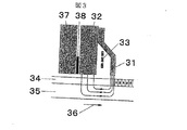
図3は垂直磁気記録の記録過程におけるヘッドと媒体の間の磁束の流れを示す模式図である。主磁極31と補助磁極32とコイル33からなる記録ヘッドと、記録層34と軟磁性裏打ち層35を有する垂直記録媒体が相対して配置される。コイルに電流を流して励磁すると、主磁極先端と軟磁性裏打ち層の間に垂直方向の磁界が生じ、これにより垂直記録媒体の記録層に記録がなされる。軟磁性裏打ち層へ流れた磁束は補助磁極へと戻り磁気回路を作る。この際主磁極の形状によって記録磁化分布が決まるが、特に、媒体移動方向36に対する下流側の主磁極端部によって記録がなされることがわかる。また、補助磁極32と下部シールド37の間に設けた磁気抵抗効果素子38により再生がなされる。
図4は本実施例に用いた磁気ヘッドの主磁極の、媒体に対向する面における形状と、記録トラックの模式図を示したものである。図4(a)はヨー角は0°の場合を、図4(b)はヨー角が0°でない場合をそれぞれ示している。
本発明の主磁極は、図4に示すように、浮上面における輪郭線形状が、リーディング側端部からトレーリング側に向かってトラック幅方向の長さが連続的に増加する第1の部分41と、該第1の部分のトレーリング側に位置する第2の部分42とを備えるように形成し、更に、第1の部分と第2の部分が接する領域のトラック幅方向の長さwが、トレーリング側端部における第2の部分のトラック幅方向の長さと同じか短くなるように形成する。リーディング側からトレーリング側に向かう第2の部分のトラック幅方向の長さの変化する割合(変化率)は、第1の部分のリーディング側からトレーリング側に向かうトラック幅方向の長さの変化率とは異なっている。
第2の部分のトレーリング側の端辺の垂線と第1の部分のトラックエッジ側の側辺とのなす角度xは、第2の部分のトレーリング側の端辺と、媒体移動方向に直交する方向とがなす角(いわゆるヨー角)の最大値sに対して、x≧sを満たす方がよい。第2の部分の厚さtは、ヨー角の最大値s、記録トラックの中心とこの記録トラックに隣接するトラックの中心との間隔をトラックピッチTとするとき、t≦0.25・T/(sin(s))を満たすことが好ましい。
本実施例では、主磁極は二つの部分からなっており、媒体移動方向44の上流側に当たる第1の部分41はリーディング側からトレーリング側に向けて幅が連続的に増加しており、この部分の厚さは350nm、トレーリング側の幅wは250nmである。媒体移動方向44の下流側に当たる第2の部分42は第1の部分41の媒体のトレーリング側の幅と同じ幅wで形成され、リーディング側からトレーリング側に向けて幅が同じである。すなわち、リーディング側からトレーリング側に向かう第2の部分42のトラック幅方向の長さは変化せず、第1の部分のリーディング側からトレーリング側に向かうトラック幅方向の長さの変化は不連続となる。より具体的に説明すると、図4の(a),(b)で、第1の部分においては、トラック幅方向の長さはリーディング側からトレーリング側へ向かう方向に対して連続的に増加しているので、トラック幅方向の長さの変化率はゼロでない一定値である。一方、第2の部分においてはトラック幅方向の長さは変化しないので、第2の部分のトラック幅方向の長さの変化率は0となる。第2の部分のトレーリング側の端辺の垂線と第1の部分のトラックエッジ側の側辺とのなす角度xは10°である。本実施例に用いた磁気ディスク装置の最大ヨー角は10°であった。これは、前記角度xと一致している。第2の部分の厚さtは100nmとした。これは、ヨー角の最大値s=10°、トラックピッチT=300nmとするとき、t≦0.25・T/(sin(s))を満たす。
主磁極の断面積は、媒体に対向する表面からこの面の法線方向に沿って磁極内部に向かう方向に距離Lyの位置までは同じ断面積を保ち、表面からの距離がLyを超えるとその断面積を増加させる。このとき第1の部分を形成する膜のLyをLy1、第2の部分を形成する膜のLyをLy2とすると、Ly1≦Ly2とするのがよい。より大きな磁界強度を得るためには、第1の部分を形成する膜の飽和磁束密度Bs1を、第2の部分を形成する膜の飽和磁束密度Bs2以上とするのがよい。より大きな磁界勾配を得るためには第2の部分を形成する膜のBs2を第1の部分を形成する膜のBs1以上とするのがよい。
本実施例では、図5に示すように、主磁極の幅wを、媒体に対向する表面からこの面の法線方向に沿って磁極内部に向かう方向に距離Lyの位置までは同じ幅を保ち、表面からの距離がLyを超えるとその幅を増加させた。このとき第1の部分と第2の部分とは同じ距離Lyを有し、本実施例ではLy=500nmとした。第1の部分と第2の部分とは同じ飽和磁束密度Bsを有しBs=1.6Tとした。このとき、ヘッド表面からの距離30nmの位置でトラック中心に沿う直線上での磁界強度分布を計算機シミュレーションにより見積もった結果が図6である。比較のため、主磁極の浮上面における輪郭線形状が、リーディング側からトレーリング側に向けて幅が連続的に増加している一つの部分からなり、主磁極の厚さが450nm、トレーリング側の幅は250nmである他は全く同じ構成の磁気ヘッドについても計算した。この場合もトレーリング側の端辺の垂線とこの端辺に交差する側辺とのなす角度xは10°である。本実施例のヘッドは比較例のヘッドに比べて約5%磁界強度が増加していた。これは磁極の断面積が異なることに起因するものであった。
図7はトラック中心から120nm離れた直線上、すなわちトラック端部での磁界強度分布を示す。本実施例のヘッドは比較例に比べて磁界強度が18%増加していることがわかる。トラックエッジでの磁界強度が増加しているため、トラックエッジの記録能力が高くなり、有効なトラック幅の増加が図れる。これらのヘッドの実効トラック幅を見積もったところ、本実施例のヘッドで243nm、比較例では225nmであった。本実施例のヘッドを用いることにより、実効トラック幅の拡大によってS/N比が改善され、本実施例の磁気ディスク装置が、所定のトラック密度で動作することが確認できた。
(実施例2)
実施例1と同様の磁気ディスク装置において、トラックピッチT=230nm、ヨー角の最大値s=13°とした。これに用いる単磁極ヘッドの主磁極の浮上面における輪郭線形状の模式図を図8に示す。リーディング側からトレーリング側に向けて幅が連続的に増加する第1の部分81のトレーリング側の幅は190nmとした。第1の部分の厚さは350nmとした。第1の部分のトレーリング側に形成された第2の部分は、リーディング側からトレーリング側に向けて幅がわずかに増加していた。すなわち第2の部分のリーディング側の幅は190nm、トレーリング側の幅は200nmであった。この場合もリーディング側からトレーリング側に向かう第2の部分のトラック幅方向の長さの変化は、第1の部分のリーディング側からトレーリング側に向かうトラック幅方向の長さの変化とは不連続である。第2の部分82の厚さtは50nmとした。第2の部分のトレーリング側の端辺の垂線と、第1の部分のトラックエッジ側の側辺とのなす角度xは15°とした。この場合、第1の部分81の形状はほぼ三角形に近い形となっている。磁極幅wが同じである長さLyに関しては第1の部分のLy1=220nm、第2の部分のLy2=500nmとした。また本実施例では第1の部分の膜の飽和磁束密度Bs1を1.6T、第1の部分の膜のBs2を2.0Tとした。比較のために第1の部分と第2の部分のBsがともに1.6Tのヘッドについても調べた。このとき、ヘッド表面からの距離30nmの位置でトラック中心に沿う直線上での磁界強度分布を計算機シミュレーションにより見積もった結果が図9である。磁界強度は両方のヘッドでほぼ同じであることがわかる。
図10は、媒体移動方向の下流側での磁界強度分布において、横軸に磁界強度、縦軸にそのときの磁界勾配をプロットしたものである。この場合、第2の部分の膜のBs2を2.0Tとしたヘッドで磁界勾配の絶対値が大きくなっていることがわかる。磁界勾配が大きくなることで記録再生時のS/N比の改善が図れる。二つのヘッドで記録した場合のS/N比では第二層目のBs2を2.0Tとした場合が、第2の部分の膜のBs2が1.6Tの場合に比べて1.3dB改善されていた。
(実施例3)
実施例2と同様のヘッドにおいて、第1の部分の膜のBs1を2.0T、第2の部分の膜のBs2を1.6Tとした他は実施例2と同じ構成の磁気ヘッドについて調べた。図11はヘッド表面からの距離30nmの位置でトラック中心に沿う直線上での磁界強度分布を計算機シミュレーションにより見積もった結果である。比較のために第1の部分の膜と第2の部分の膜のBsがともに1.6Tのヘッドの結果も示した。第1の部分の膜のBsが2.0Tのヘッドは磁界強度が約15%増加していることがわかる。これにより保磁力の大きな記録媒体に対しても十分な記録ができる。本実施例のヘッドは保磁力4.7kOeの媒体に対して記録密度88kFCIで記録した上に記録密度700kFCIでオーバーライトした際、オーバーライト値32dBを示した。
(実施例4)
実施例1と同様のヘッドにおいて、第2の部分の厚さtを100nm、200nm、300nmとした。本実施例では、ヨー角の最大値s=15°である。第2の部分のトレーリング側の端辺の垂線と、第1の部分のトラックエッジ側の側辺とのなす角度xは17°とした。トラックピッチT=300nmとするとき、t≦0.25・T/(sin(s))を満たすのはtが100nm、200nmの場合である。このとき、ヘッド表面からの距離30nmの位置でトラック中心に沿う直線上での磁界強度の最大値を見積もった結果が図12である。第2の部分の厚さが厚いほど磁界強度が増加した。次にこれらのヘッドの記録にじみ量を見積もったところ図13のようになった。装置の記録にじみの許容量がトラックピッチの25%とすると、トラックピッチT=300nmの場合の最大許容記録にじみ量は75nmである。したがってヨー角の最大値s=15°のときの、第2の部分の厚さの許容最大値は0.25・T/(sin(s))=290nmである。t=300nmのヘッドは記録にじみ量が大きくオフトラックマージンが不足するためトラックピッチT=300nmを実現できない。すなわち本発明の効果はt≦0.25・T/(sin(s))を満たす場合に有効に作用する。
(実施例5)
図14は本実施例に用いた磁気ヘッドの主磁極の、媒体に対向する面における形状である。主磁極は三つの部分からなっており、最もリーディング側に当たる第1の部分141はリーディング側からトレーリング側に向けて幅が連続的に増加している。第1の部分の厚さは350nmとした。第1の部分のトレーリング側の幅は190nmである。
第1の部分のトレーリング側に形成された第2の部分142は、リーディング側の幅は第1の部分141のトレーリング側の幅と同じ幅で形成され、リーディング側からトレーリング側に向けて幅がわずかに増加していた。第2の部分の厚さt2は50nmとした。さらに第2の部分のトレーリング側に当たる第3の部分143は第2の部分142のトレーリング側の幅と同じ幅で形成され、リーディング側からトレーリング側に向けて幅が同じであった。この幅は200nmであった。第3の部分の厚さt3は50nmとした。この場合、リーディング側からトレーリング側に向かうトラック幅方向の長さの変化は、第1の部分と第2の部分の接する個所と、第2の部分と第3の部分の接する個所において不連続である。第3の部分のトレーリング側の端辺の垂線と第1の部分のトラックエッジ側の側辺とのなす角度xは15°である。この場合、ヨー角の最大値s=13°、第3の部分のトラック幅w=200nm、トラックピッチT=230nmとするとき、第2の部分の厚さと第3の部分の厚さの合計t´はt´≦0.25・T/(sin(s))を満たす。
第1の部分のLyをLy1、第2の部分のLyをLy2、第3の部分のLyをLy3とすると、本実施例ではLy1=Ly2=Ly3=500nmとした。第1の部分の膜の飽和磁束密度Bsと第2の部分の膜のBsは同じで1.8Tとし、第3の部分の膜のBsは2.0Tとした。このヘッドの記録にじみ量は約18nmと小さく、S/N比も実施例2のヘッドに比較してさらに0.7dB改善されていた。
(実施例6)
実施例1〜5で説明したような主磁極を作製する方法は、無機絶縁膜上にレジストパターンを形成する工程と、このレジストパターンをマスクとして無機絶縁膜を異方性エッチングし側壁が膜面に対して垂直な溝を形成する工程と、テーパーエッチングにより側壁が傾斜した溝を形成する工程と、レジストパターンを除去する工程と、この溝を含む無機絶縁膜上に磁性膜を形成する工程と、この磁性膜をケミカルメカニカルポリッシング(CMP)またはエッチングにより平坦化する工程を順次行う。
また、平坦化の工程において、無機絶縁膜に対して磁性膜がくぼんだ状態まで除去した後、別の磁性膜を形成する工程と、磁性膜上面を平坦化する工程をさらに順次行ってもよい。また、別の方法では、第一の無機絶縁膜上に別の材料からなる第二の無機絶縁膜を形成する工程と、第二の無機絶縁膜上にレジストパターンを形成する工程と、このレジストパターンをマスクとして第二の無機絶縁膜を異方性エッチングし側壁が膜面に対して垂直な溝を形成する工程と、第一の無機絶縁膜をテーパーエッチングにより側壁が傾斜した溝を形成する工程と、レジストパターンを除去する工程と、この溝を含む無機絶縁膜上に磁性膜を形成する工程と、この磁性膜をケミカルメカニカルポリッシング(CMP)またはエッチングにより無機絶縁膜に対して磁性膜がくぼんだ状態まで除去する工程と、別の磁性膜を形成する工程と、磁性膜上面を平坦化する工程を順次行う。
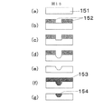
図15に、本発明の磁気ヘッドの主磁極の製造工程の該略図を示す(但し、図の拡大倍率は均一では無い)。再生ヘッド部は省略している。(a)の無機絶縁膜151上にレジストパターン152を形成したところを(b)に示す。無機絶縁膜は、従来用いられているAl2O3を用いたが、他にSiC、AlN、Ta2O5、TiC、TiO2、SiO2等が使用可能である。レジストパターンは、KrFエキシマレーザーステッパを用いて露光を行い、レジストとしては、東京応化工業(株)製ポジレジストTDUR−P201を用いた。レジスト膜厚0.7μmを用いた場合、0.2μmが解像できた。このレジストパターンをマスクとして用いて、無機絶縁膜を異方性のエッチングを行ったところを(c)に示す。
Al2O3を用いた場合は、エッチングガスとしてBCl3またはBCl3とCl2またはBCl3とArの混合ガスを用いれば良い。他にAlNを用いた場合は、上記の塩素系ガスが良いが、エッチングしやすいTa2O5、TiC、TiO2、SiO2、SiC等を用いた場合は、フッ素系のCHF3、CF4、SF6、C4F8等を用いることができる。エッチング深さは0.2μmとした。(d)続いて、エッチング条件を変更し、テーパエッチングを行う。Al2O3をエッチングする場合、例えばBCl3にCHF3を添加したものが使用できる。エッチング後、レジストを除去したところを(e)に示す。(f)次に磁性膜153の形成を行う。めっき法を用いる場合は、めっき下地膜を形成後、電気めっきを行う。磁性材料としては、CoNiFe、FeNi、CoFeCu、FeCo等を使用できる。ここでは図示していないが、めっき下地膜後工程において、平坦化のためにCMPを用いる場合はCMP用のストッパ膜を設け、エッチングを行う場合はエッチングストッパを設けることができる。平坦化工程において、膜厚の制御性が十分である場合は、このストッパ膜の形成工程を省略することも可能である。
CMP用のストッパ膜としてはC、Ta、Mo、Nb、W、Cr等の単層膜や合金膜積層膜が使用可能である。今回は、Cをスパッタしたものを用いた。Cは、化学的に安定なため、化学的には研摩されず、機械的に研摩された場合は、研摩廃液の色が黒色になるため、研摩の終点が検知しやすく、主磁極の膜厚制御性が向上する。
エッチングストッパ膜としては、貴金属類が反応性エッチングされないため使用可能で、Au、Pt、Pd、Ru、Rh、Cu、Ag、Tc、Re、Os、Irの単層膜または積層膜または合金膜がよい。他にCr、Ni等も反応性エッチングされないため、使用可能である。これらは、全てスパッタ法で形成可能である。次に磁性膜を形成したところを(f)に示す。形成方法は、メッキでもスパッタ法でもどちらでもよい。電解メッキの場合は、メッキの下地膜を形成後、メッキする必要がある。スパッタ法の場合は、c、d及びeの工程で形成した溝のアスペクト比が大きいため、指向性のよい方法、例えばロングスロースパッタ、コリメーションスパッタ法等を用いて、磁性膜の中に空隙が形成しないようにする必要がある。電解メッキ法を用いる場合、飽和磁束密度が1.6TのFe55Ni45または、飽和磁束密度が2.2TのCoNiFeを用いることができる。メッキ下地膜は、メッキ膜と同じ組成の磁性膜を用いても、非磁性膜を用いてもよい。(g)に磁性膜上面の平坦化を行い、主磁極154を形成したところを示す。平坦化は、CMP等の研摩法を用いれば、ストッパ膜で研摩をストップすることにより、膜厚を制御できると同時に上面の完全な平坦化が可能で、トラック幅となる溝の中全体で1nm以下の平坦化が可能であった。このときトラック幅は、(b)の工程のレジストパターンと同じ0.2μmが得られ、主磁極下部側面のテーパ角度は、(d)の工程で形成したままの10°であった。また、この平坦化工程において、エッチングを用いた場合は、一旦、レジストを塗布し、塩素系ガス、例えばBCl3またはBCl3とCl2の混合ガスを用いて、エッチングを行い、(即ちいわゆるエッチバックにより)、平坦化を行うことが可能である。このときは、上記の貴金属類からなるストッパ膜やNi、Cr等のストッパ膜が有効である。本実施例における製造方法に従えば、多数の素子を作製した際のトラック幅のばらつきが少なく、トラック幅の作製精度が高くなる利点があった。
以上、本発明の主磁極の製造方法に従えば、多数の素子を作製した際のトラック幅のばらつきが少なく、トラック幅の公差を小さくすることができる。
(実施例7)
本実施例は実施例6と同様の本発明の主磁極の製造工程において、図16に示す通り(a)〜(f)は、図15と同様である。(g)の工程において、例えばCMPのスラリーの酸性度を高め、磁性膜が無機絶縁膜に対して、窪んだ形状、いわゆるディッシングした状態にする。(h)の工程において、例えばスパッタ法で磁性膜164を形成する。このとき例えば、飽和磁束密度Bsが2.4TのFeCoのような材料を用いることができる。上面に、高飽和密度の材料を用いることで、ヘッドからの磁界勾配をより急峻にすることが可能で、記録特性を向上させることができる。(i)の工程において、今度は(g)とは別のスラリーを用いて、磁性膜上面を平坦化し、主磁極165を得た。
(実施例8)
図17に、本発明の主磁極の製造工程の該略図を示す(但し、図の拡大倍率は均一では無い)。再生ヘッド部は省略している。(a)には、無機絶縁膜171上に、別の材料からなる無機絶縁膜176を形成したところを示す。無機絶縁膜171にAl2O3を用いた場合、無機絶縁膜176には、例えばSiO2を用いることができる。(b)この上にレジストパターン172を形成したところを示す。(c)では、レジストパターン172をマスクに無機絶縁膜176をエッチングしたところを示す。無機絶縁膜176にSiO2を用いた場合、エッチングガスとして、例えばCHF3、CF4等が使用でき、側面形状を垂直に形成できる。(d)では、無機絶縁膜171を、例えばBCl3のガスを用いて、エッチングしたところを示す。本工程では、側面をテーパ形状にエッチングする。無機絶縁膜171と無機絶縁膜176で材料が異なっているため、エッチング条件を変えることで、形状制御を行いやすい。(e)では、レジストパターン172を除去したところを示す。(f)では、磁性膜173を形成したところを示す。(g)において、図16と同様に磁性膜を無機絶縁膜176からディッシングするように加工したところを示す。(h)において、磁性膜174を形成したところを示す。(i)において、磁性膜174の上面を平坦化し、主磁極175を得た。
(実施例9)
本発明の第9の実施例は、
無機絶縁膜上にレジストパターンを形成する工程と、前記レジストパターンをマスクとして前記無機絶縁膜を異方性エッチングし側壁が膜面に対してほぼ垂直な溝を形成する工程と、テーパーエッチングにより側壁が傾斜した溝を形成する工程と、前記レジストパターンを除去する工程と、この溝を含む前記無機絶縁膜上に磁性膜を形成する工程と、前記磁性膜をケミカルメカニカルポリッシング(CMP)またはエッチングにより平坦化する工程を順次行うことにより主磁極を形成することを特徴とする単磁極ヘッドの製造方法にある。
【0007】
また、無機絶縁膜上にレジストパターンを形成する工程と、前記レジストパターンをマスクとして前記無機絶縁膜を異方性エッチングし側壁が膜面に対してほぼ垂直な溝を形成する工程と、テーパーエッチングにより側壁が傾斜した溝を形成する工程と、前記レジストパターンを除去する工程と、この溝を含む前記無機絶縁膜上に第一の磁性膜を形成する工程と、前記第一の磁性膜をケミカルメカニカルポリッシング(CMP)またはエッチングにより前記無機絶縁膜に対して前記第一の磁性膜がくぼんだ状態まで除去する工程と、前記第一の磁性膜を有する溝を含む前記無機絶縁膜上に第二の磁性膜を形成する工程と、前記第二の磁性膜の上面を平坦化する工程を順次行うことにより主磁極を形成することを特徴とする単磁極ヘッドの製造方法にある。
【0008】
或いはまた、第一の無機絶縁膜上に別の材料からなる第二の無機絶縁膜を形成する工程と、前記第二の無機絶縁膜上にレジストパターンを形成する工程と、前記レジストパターンをマスクとして前記第二の無機絶縁膜を異方性エッチングし側壁が膜面に対してほぼ垂直な溝を形成する工程と、前記第一の無機絶縁膜をテーパーエッチングにより側壁が傾斜した溝を形成する工程と、前記レジストパターンを除去する工程と、この溝を含む前記無機絶縁膜上に第一の磁性膜を形成する工程と、前記第一の磁性膜をケミカルメカニカルポリッシング(CMP)またはエッチングにより前記無機絶縁膜に対して前記第一の磁性膜がくぼんだ状態まで除去する工程と、前記第一の磁性膜を有する溝を含む前記無機絶縁膜上に第二の磁性膜を形成する工程と、前記第二の磁性膜上面を平坦化する工程を順次行うことにより主磁極を形成することを特徴とする単磁極ヘッドの製造方法、にある。
(実施例10)
本発明の第10の実施例は、
主磁極を有する記録素子と、再生素子とを備えた磁気ヘッドと、空気流入端と空気流出端とを備えたスライダとを有し、前記主磁極は、第1の部分と該第1の部分の空気流出端側に設けられた第2の部分とを備え、該第2の部分の厚さは第1の部分の厚さよりも小さく、磁気ヘッド浮上面における前記第1の部分の輪郭線形状は、トラック幅方向の長さが前記空気流入端側から空気流出端側にかけて連続的に増加する形状であることを特徴とする磁気ヘッドスライダである。
【0009】
ヘッドスライダの概略図を図19に示す。磁気ヘッドスライダ191は、浮上面192にレール196および197を備え、回転する垂直磁気記録媒体上に配置した際、空気流入端193から空気流出端194への気流により浮上させることができる。空気流出端側の端部に磁気ヘッド素子部195を備え、磁気ヘッド素子との情報の入出力を行うための電極198を設けている。
(実施例11)
本発明の第11の実施例は、
主磁極を有する記録素子と、再生素子とを備えた磁気ヘッドと、空気流入端と空気流出端とを備えたスライダと、該スライダを支持するサスペンションと、該サスペンションを支持するロータリーアクチュエータと、前記磁気ヘッドに対向して設けられた磁気ディスク媒体とを有し、前記主磁極は、第1の部分と該第1の部分の空気流出端側に設けられた第2の部分とを備え、該第2の部分の厚さは第1の部分の厚さよりも小さく、磁気ヘッド浮上面における前記第1の部分の輪郭線形状は、トラック幅方向の長さが前記空気流入端側から空気流出端側にかけて連続的に増加する形状であることを特徴とするヘッドディスクアッセンブリである。
また、請求項19に記載のヘッドディスクアセンブリにおいて、前記磁気ディスク媒体は複数の記録トラックを備え、主磁極の前記第2の部分の厚さをt、ヨー角の最大値をs、前記複数の記録トラックのうちの任意のトラックの中心と、該記録トラックに隣接するトラックの中心との間隔をトラックピッチTとするとき、t≦0.25・T/(sin(s))を満たすことを特徴とするヘッドディスクアッセンブリ、にある。
【0010】
【発明の効果】
本発明は、垂直磁気記録用磁気ヘッドにおいて、少なくとも二つの部分からなり、第1の部分は媒体移動方向の上流側から下流側に向けて幅が連続的に増加し、第2の部分は第1の部分の媒体移動方向の下流側の幅と同じ幅でかつ媒体移動方向の上流側から下流側に向けてほぼ等しい幅で形成された構造を有する主磁極を用いた結果、記録にじみを抑制しながら、トラックエッジの記録能力を高め、実効トラック幅の減少を防ぐことができる。第2の部分を形成する膜の飽和磁束密度を高くすることにより、記録磁界勾配が急峻になり、S/N比を改善することができる。あるいは、第1の部分を形成する膜の飽和磁束密度を高くすることにより記録磁界の絶対値を増加させ、高保磁力の記録媒体に対して有効な記録能力が得られる。
本発明の主磁極の製造方法に従えば、多数の素子を作製した際のトラック幅のばらつきが少なく、トラック幅の公差を小さくすることができる。さらに、このようなヘッドを用いてトラック密度を向上させた磁気ディスク装置を提供することができる。
【図面の簡単な説明】
【図1】従来の主磁極形状と記録トラックを示す模式図である。
【図2】本発明の一実施例の磁気ディスク装置の概略図である。
【図3】垂直磁気記録の記録過程における磁束の流れを示す模式図である。
【図4】本発明の一実施例の主磁極形状と記録トラックを示す模式図である。
【図5】本発明の一実施例の主磁極構造を示した図である。
【図6】本発明の一実施例の磁界強度分布を示した図である。
【図7】本発明の一実施例の磁界強度分布を示した図である。
【図8】本発明の一実施例の主磁極構造を示す模式図である。
【図9】本発明の一実施例の磁界強度分布を示した図である。
【図10】本発明の一実施例の磁界強度に対する磁界勾配の変化を示す図である。
【図11】本発明の一実施例の磁界強度分布を示した図である。
【図12】本発明の一実施例の磁界強度の膜厚依存性を示した図である。
【図13】本発明の一実施例の記録にじみ量の膜厚依存性を示した図である。
【図14】本発明の一実施例の主磁極構造を示す模式図である。
【図15】本発明の一実施例の製造工程を示す概略図である。
【図16】本発明の一実施例の製造工程を示す概略図である。
【図17】本発明の一実施例の製造工程を示す概略図である。
【図18】本発明の一実施例の磁気ディスク装置の概略図である。
【図19】本発明の一実施例の磁気ヘッドスライダの概略図である。
【符号の説明】
11、26、43、187…記録トラック、12、154、165、175…主磁極、13…記録にじみ、14…記録不十分領域、15、36、44…媒体移動方向、21、181…ロータリーアクチュエータ、22、182…サスペンションアーム、23、183…スライダ、24、184、195…磁気ヘッド素子部、25、186…垂直磁気記録媒体、27、185…ディスク回転方向、28…ヨー角、31…主磁極、32…補助磁極、33…コイル、34…記録層、35…軟磁性裏打ち層、37…下部シールド、38…磁気抵抗効果素子、41、81、141…主磁極の第1の部分、42、82、142…主磁極の第2の部分、83、144…ヨー角0°のときの媒体移動方向、143…主磁極の第3の部分、151、161…無機絶縁膜、152、162、172…レジスト、153…磁性膜、163、173…第一の磁性膜、164、174…第二の磁性膜、171…第一の無機絶縁膜、176…第二の無機絶縁膜、191…磁気ヘッドスライダ、192…浮上面、193…空気流入端、194…空気流出端、196、197…レール、198…電極。[0001]
BACKGROUND OF THE INVENTION
The present invention relates to a main magnetic pole structure of a magnetic head for perpendicular magnetic recording, a method for manufacturing the same, and a magnetic disk device on which the main magnetic pole structure is mounted.
[0002]
[Prior art]
In order to improve the surface recording density of the magnetic disk, it is conceivable to use a perpendicular magnetic recording system in place of the conventional in-plane magnetic recording system. Perpendicular magnetic recording has the advantage that the direction of recording magnetization formed on a recording medium is perpendicular to the film surface, and fine recording magnetization is thermally stable. As a magnetic head used for perpendicular magnetic recording, a recording / reproducing separation head can be considered, and a magnetoresistive head is used as the reproducing head, but it is necessary to use a single pole head composed of a main magnetic pole and an auxiliary magnetic pole as the recording head. . In the single-pole head, a magnetic field necessary for recording is generated from the main pole processed according to the recording track width. For this reason, the shape of the main pole on the head surface facing the recording medium greatly affects the recording magnetization distribution. For example, as shown in FIGS. 1A and 1B, when the shape of the
[0003]
[Problems to be solved by the invention]
The above prior art is designed to reduce the recording blur when the yaw angle is applied, but the magnetic pole thickness decreases at the track edge portion. There is a problem that the effective track width becomes narrow. This hinders improvement in track density. An object of the present invention is to improve the track edge recording capability and prevent the effective track width from being reduced while suppressing recording blur. Another object of the present invention is to provide a magnetic disk drive having an improved track density using such a head.
[0004]
[Means for Solving the Problems]
In order to achieve the above object, the main magnetic pole of the present invention is such that the contour line shape on the air bearing surface is directed from the upstream side (ie, leading side) end in the medium movement direction to the downstream side (ie, trailing side) in the medium movement direction. A first portion whose length in the track width direction continuously increases, and a second portion located on the trailing side of the first portion, and further comprising: The length in the track width direction of the region in contact with the second portion is formed to be the same as or shorter than the length in the track width direction of the second portion at the trailing end.
[0005]
By using a magnetic head having such a contoured shape and having a main magnetic pole, it is possible to improve the recording capability of the track edge and prevent the effective track width from being reduced while suppressing the recording blur. Furthermore, a magnetic disk device with improved track density can be provided by mounting a magnetic head having the main pole of the present invention.
[0006]
DETAILED DESCRIPTION OF THE INVENTION
Example 1
FIG. 18 is a schematic diagram of a magnetic disk device as an example of an embodiment of the present invention. A
FIG. 3 is a schematic diagram showing the flow of magnetic flux between the head and the medium in the recording process of perpendicular magnetic recording. A recording head composed of a main
FIG. 4 shows the shape of the main pole of the magnetic head used in this embodiment on the surface facing the medium and a schematic diagram of the recording track. FIG. 4A shows a case where the yaw angle is 0 °, and FIG. 4B shows a case where the yaw angle is not 0 °.
As shown in FIG. 4, the main magnetic pole of the present invention has a
The angle x formed by the perpendicular of the trailing edge of the second part and the side of the first part on the track edge side is orthogonal to the trailing edge of the second part and in the medium moving direction. It is better to satisfy x ≧ s with respect to the maximum value s of the angle (so-called yaw angle) formed by the direction to be performed. The thickness t of the second portion is the maximum value s of the yaw angle, and when the distance between the center of the recording track and the center of the track adjacent to this recording track is the track pitch T, t ≦ 0.25 · T / It is preferable to satisfy (sin (s)).
In this embodiment, the main magnetic pole is composed of two parts, and the width of the
The cross-sectional area of the main magnetic pole maintains the same cross-sectional area from the surface facing the medium to the position of the distance Ly in the direction toward the inside of the magnetic pole along the normal direction of this surface, and when the distance from the surface exceeds Ly, Increase cross-sectional area. At this time, if Ly of the film forming the first portion is Ly1 and Ly of the film forming the second portion is Ly2, it is preferable to satisfy Ly1 ≦ Ly2. In order to obtain a larger magnetic field strength, the saturation magnetic flux density Bs1 of the film forming the first portion is preferably set to be equal to or higher than the saturation magnetic flux density Bs2 of the film forming the second portion. In order to obtain a larger magnetic field gradient, Bs2 of the film forming the second portion is preferably set to be equal to or higher than Bs1 of the film forming the first portion.
In this embodiment, as shown in FIG. 5, the width w of the main magnetic pole is kept the same width from the surface facing the medium to the position of the distance Ly in the direction toward the inside of the magnetic pole along the normal direction of this surface. When the distance from the surface exceeds Ly, the width is increased. At this time, the first portion and the second portion have the same distance Ly, and Ly = 500 nm in this embodiment. The first portion and the second portion have the same saturation magnetic flux density Bs, and Bs = 1.6T. At this time, FIG. 6 shows the result of estimating the magnetic field strength distribution on a straight line along the track center at a distance of 30 nm from the head surface by computer simulation. For comparison, the contour shape on the air bearing surface of the main pole consists of one part whose width continuously increases from the leading side to the trailing side, the main pole thickness is 450 nm, and the trailing side The calculation was performed for a magnetic head having the same configuration except that the width of the magnetic head was 250 nm. Also in this case, the angle x formed by the perpendicular of the trailing edge and the side intersecting this edge is 10 °. The head of this example was about 5% stronger than the head of the comparative example. This was caused by the difference in the cross-sectional areas of the magnetic poles.
FIG. 7 shows the magnetic field strength distribution on a straight line 120 nm away from the track center, that is, at the track end. It can be seen that the magnetic field strength of the head of this example is increased by 18% compared to the comparative example. Since the magnetic field strength at the track edge is increased, the recording capability of the track edge is increased, and the effective track width can be increased. When the effective track width of these heads was estimated, it was 243 nm for the head of this example and 225 nm for the comparative example. By using the head of this example, the S / N ratio was improved by increasing the effective track width, and it was confirmed that the magnetic disk device of this example was operated at a predetermined track density.
(Example 2)
In the same magnetic disk device as in Example 1, the track pitch T = 230 nm and the maximum yaw angle s = 13 °. FIG. 8 shows a schematic diagram of the contour shape on the air bearing surface of the main pole of the single pole head used for this. The width on the trailing side of the
FIG. 10 plots the magnetic field strength on the horizontal axis and the magnetic field gradient at that time on the vertical axis in the magnetic field strength distribution on the downstream side in the medium moving direction. In this case, it can be seen that the absolute value of the magnetic field gradient is large in the head in which the Bs2 of the second portion film is 2.0T. By increasing the magnetic field gradient, it is possible to improve the S / N ratio during recording and reproduction. In the S / N ratio when recording with two heads, when the second layer Bs2 is set to 2.0T, the Bs2 of the second part film is improved by 1.3 dB compared to the case where the Bs2 of the film is 1.6T. It was.
(Example 3)
In the same head as in Example 2, a magnetic head having the same configuration as in Example 2 was examined except that Bs1 of the first part film was 2.0T and Bs2 of the second part film was 1.6T. . FIG. 11 shows the result of estimating the magnetic field strength distribution on a straight line along the track center at a distance of 30 nm from the head surface by computer simulation. For comparison, the result of a head in which both Bs of the first part film and the second part film are 1.6 T is also shown. It can be seen that the magnetic field strength of the head having the Bs of 2.0T in the first portion is increased by about 15%. Thus, sufficient recording can be performed even on a recording medium having a large coercive force. The head of this example showed an overwrite value of 32 dB when recording on a medium having a coercive force of 4.7 kOe at a recording density of 88 kFCI and overwriting at a recording density of 700 kFCI.
Example 4
In the same head as in Example 1, the thickness t of the second portion was set to 100 nm, 200 nm, and 300 nm. In this embodiment, the maximum yaw angle s = 15 °. The angle x formed by the perpendicular line on the trailing edge of the second part and the side edge on the track edge side of the first part was 17 °. When the track pitch T = 300 nm, t ≦ 0.25 · T / (sin (s)) is satisfied when t is 100 nm and 200 nm. At this time, FIG. 12 shows the result of estimating the maximum value of the magnetic field strength on the straight line along the track center at a position of 30 nm from the head surface. The magnetic field strength increased as the thickness of the second part increased. Next, when the amount of recording blur of these heads was estimated, it was as shown in FIG. When the allowable amount of recording blur of the apparatus is 25% of the track pitch, the maximum allowable recording blur amount when the track pitch T = 300 nm is 75 nm. Therefore, when the maximum value of the yaw angle s = 15 °, the allowable maximum value of the thickness of the second portion is 0.25 · T / (sin (s)) = 290 nm. A head with t = 300 nm has a large recording bleeding amount and lacks an off-track margin, so that a track pitch T = 300 nm cannot be realized. That is, the effect of the present invention is effective when t ≦ 0.25 · T / (sin (s)) is satisfied.
(Example 5)
FIG. 14 shows the shape of the main pole of the magnetic head used in this embodiment on the surface facing the medium. The main magnetic pole is composed of three parts, and the width of the
The
In the present embodiment, Ly1 = Ly2 = Ly3 = 500 nm, where Ly of the first part is Ly1, Ly of the second part is Ly2, and Ly of the third part is Ly3. The saturation magnetic flux density Bs of the first part film and the Bs of the second part film were the same, 1.8T, and the Bs of the third part film was 2.0T. The recording blur amount of this head was as small as about 18 nm, and the S / N ratio was further improved by 0.7 dB compared to the head of Example 2.
(Example 6)
The method of manufacturing the main magnetic pole as described in Examples 1 to 5 includes a step of forming a resist pattern on the inorganic insulating film, and anisotropic etching of the inorganic insulating film using the resist pattern as a mask to form a sidewall on the film surface. Forming a groove perpendicular to the substrate, forming a groove whose sidewall is inclined by taper etching, removing the resist pattern, and forming a magnetic film on the inorganic insulating film including the groove; Then, a step of planarizing the magnetic film by chemical mechanical polishing (CMP) or etching is sequentially performed.
Further, in the planarization step, after the magnetic film is removed from the inorganic insulating film until it is depressed, another step of forming another magnetic film and a step of planarizing the upper surface of the magnetic film may be further sequentially performed. . In another method, a step of forming a second inorganic insulating film made of another material on the first inorganic insulating film, a step of forming a resist pattern on the second inorganic insulating film, and the resist Using the pattern as a mask, anisotropically etching the second inorganic insulating film to form a groove whose side wall is perpendicular to the film surface, and forming a groove whose side wall is inclined by taper etching the first inorganic insulating film A step of removing a resist pattern, a step of forming a magnetic film on the inorganic insulating film including the groove, and a magnetic film is formed on the inorganic insulating film by chemical mechanical polishing (CMP) or etching. A step of removing the concave portion, a step of forming another magnetic film, and a step of flattening the upper surface of the magnetic film are sequentially performed.
FIG. 15 shows a schematic diagram of the manufacturing process of the main pole of the magnetic head of the present invention (however, the magnification of the drawing is not uniform). The reproducing head part is omitted. (B) shows a state where a resist
When Al 2 O 3 is used, BCl 3 or a mixed gas of BCl 3 and Cl 2 or BCl 3 and Ar may be used as an etching gas. In addition, when AlN is used, the above chlorine-based gas is preferable. However, when Ta2O5, TiC, TiO2, SiO2, SiC, etc., which are easy to etch, are used, fluorine-based CHF3, CF4, SF6, C4F8, etc. are used. be able to. The etching depth was 0.2 μm. (D) Subsequently, the etching conditions are changed, and taper etching is performed. Al 2 O 3 For example, BCl 3 To CHF 3 Can be used. A portion where the resist is removed after the etching is shown in FIG. (F) Next, the
As a stopper film for CMP, a single layer film such as C, Ta, Mo, Nb, W, Cr, or an alloy film laminated film can be used. This time, C sputtered one was used. Since C is chemically stable, it is not chemically polished, and when mechanically polished, the color of the polishing waste liquid is black, so that the end point of polishing is easy to detect, and the film thickness of the main pole Controllability is improved.
As an etching stopper film, noble metals can be used because they are not reactively etched, and Au, Pt, Pd, Ru, Rh, Cu, Ag, Tc, Re, Os, Ir single layer film, laminated film or alloy film can be used. Good. In addition, Cr, Ni, etc. can be used because they are not reactively etched. These can all be formed by sputtering. Next, the place where the magnetic film is formed is shown in FIG. The formation method may be either plating or sputtering. In the case of electrolytic plating, it is necessary to plate after forming a base film for plating. In the case of the sputtering method, since the aspect ratio of the groove formed in the steps c, d, and e is large, voids are formed in the magnetic film by using a method having good directivity, for example, long throw sputtering, collimation sputtering, or the like. It is necessary not to form. When electrolytic plating is used, Fe with a saturation magnetic flux density of 1.6T 55 Ni 45 Alternatively, CoNiFe having a saturation magnetic flux density of 2.2T can be used. The plating base film may be a magnetic film having the same composition as the plating film or a non-magnetic film. (G) shows a state where the top surface of the magnetic film is planarized to form the main
As described above, according to the method for manufacturing a main magnetic pole of the present invention, there is little variation in track width when a large number of elements are manufactured, and the tolerance of track width can be reduced.
(Example 7)
In the present embodiment, the main magnetic pole manufacturing process of the present invention is the same as that of the sixth embodiment, and (a) to (f) are the same as FIG. 15 as shown in FIG. In the step (g), for example, the acidity of the CMP slurry is increased so that the magnetic film is in a recessed shape, that is, a dishing state with respect to the inorganic insulating film. In the step (h), the
(Example 8)
FIG. 17 shows a schematic diagram of the manufacturing process of the main magnetic pole of the present invention (however, the magnification of the drawing is not uniform). The reproducing head part is omitted. FIG. 4A shows a case where an inorganic
Example 9
The ninth embodiment of the present invention
Forming a resist pattern on the inorganic insulating film; performing anisotropic etching on the inorganic insulating film using the resist pattern as a mask to form a groove whose side wall is substantially perpendicular to the film surface; and side wall by taper etching. Forming a groove having a slope, removing the resist pattern, forming a magnetic film on the inorganic insulating film including the groove, and chemical mechanical polishing (CMP) or etching the magnetic film. A method of manufacturing a single pole head is characterized in that a main pole is formed by sequentially performing a flattening step.
[0007]
A step of forming a resist pattern on the inorganic insulating film; a step of anisotropically etching the inorganic insulating film by using the resist pattern as a mask to form a groove whose side wall is substantially perpendicular to the film surface; and taper etching. Forming a groove having an inclined sidewall, removing the resist pattern, forming a first magnetic film on the inorganic insulating film including the groove, and chemically treating the first magnetic film. Removing the first magnetic film from the inorganic insulating film until it is depressed by mechanical polishing (CMP) or etching; and forming a second on the inorganic insulating film including a groove having the first magnetic film. A main pole is formed by sequentially performing a step of forming a magnetic film and a step of flattening the upper surface of the second magnetic film. There is the law.
[0008]
Alternatively, a step of forming a second inorganic insulating film made of another material on the first inorganic insulating film, a step of forming a resist pattern on the second inorganic insulating film, and a mask of the resist pattern A step of anisotropically etching the second inorganic insulating film to form a groove whose sidewall is substantially perpendicular to the film surface, and a groove having a sidewall inclined by taper etching of the first inorganic insulating film. A step of removing the resist pattern, a step of forming a first magnetic film on the inorganic insulating film including the grooves, and the first magnetic film by chemical mechanical polishing (CMP) or etching. A step of removing the first magnetic film from the insulative state with respect to the inorganic insulating film; and a step of forming a second magnetic film on the inorganic insulating film including the groove having the first magnetic film. When a method for producing a single-pole head and forming a main pole by sequentially performing the step of planarizing the second magnetic film top surface, in.
(Example 10)
The tenth embodiment of the present invention
A magnetic head having a recording element having a main magnetic pole; a reproducing element; and a slider having an air inflow end and an air outflow end. The main magnetic pole has a first portion and the first portion. A second portion provided on the air outflow end side of the magnetic head, the thickness of the second portion being smaller than the thickness of the first portion, and the contour shape of the first portion on the air bearing surface of the magnetic head Is a shape in which the length in the track width direction continuously increases from the air inflow end side to the air outflow end side.
[0009]
A schematic diagram of the head slider is shown in FIG. The
(Example 11)
The eleventh embodiment of the present invention is
A magnetic head having a recording element having a main magnetic pole, a reproducing element, a slider having an air inflow end and an air outflow end, a suspension supporting the slider, a rotary actuator supporting the suspension, A magnetic disk medium provided opposite to the magnetic head, wherein the main pole includes a first portion and a second portion provided on the air outflow end side of the first portion, The thickness of the second part is smaller than the thickness of the first part, and the contour shape of the first part on the air bearing surface of the magnetic head is such that the length in the track width direction is from the air inflow end side to the air outflow end side. A head disk assembly having a shape that continuously increases toward the side.
20. The head disk assembly according to
[0010]
【The invention's effect】
In the magnetic head for perpendicular magnetic recording, the present invention comprises at least two parts, the first part continuously increases in width from the upstream side to the downstream side in the medium moving direction, and the second part is the first part. As a result of using a main pole having a structure having the same width as the downstream width in the medium moving direction of the
According to the method for manufacturing a main magnetic pole of the present invention, there is little variation in track width when a large number of elements are manufactured, and the tolerance of track width can be reduced. Furthermore, it is possible to provide a magnetic disk device with an improved track density using such a head.
[Brief description of the drawings]
FIG. 1 is a schematic diagram showing a conventional main magnetic pole shape and a recording track.
FIG. 2 is a schematic view of a magnetic disk device according to an embodiment of the present invention.
FIG. 3 is a schematic diagram showing the flow of magnetic flux in the recording process of perpendicular magnetic recording.
FIG. 4 is a schematic diagram showing a main magnetic pole shape and a recording track according to an embodiment of the present invention.
FIG. 5 is a view showing a main magnetic pole structure according to an embodiment of the present invention.
FIG. 6 is a diagram showing a magnetic field strength distribution according to an embodiment of the present invention.
FIG. 7 is a diagram showing a magnetic field strength distribution according to an embodiment of the present invention.
FIG. 8 is a schematic diagram showing a main magnetic pole structure according to an embodiment of the present invention.
FIG. 9 is a diagram showing a magnetic field strength distribution according to an embodiment of the present invention.
FIG. 10 is a diagram showing a change in magnetic field gradient with respect to the magnetic field strength in one embodiment of the present invention.
FIG. 11 is a diagram showing a magnetic field strength distribution according to an embodiment of the present invention.
FIG. 12 is a diagram showing the film thickness dependence of the magnetic field strength in one example of the present invention.
FIG. 13 is a diagram showing the film thickness dependence of the amount of recording blur in one embodiment of the present invention.
FIG. 14 is a schematic diagram showing a main magnetic pole structure according to an embodiment of the present invention.
FIG. 15 is a schematic view showing a manufacturing process according to an embodiment of the present invention.
FIG. 16 is a schematic view showing a manufacturing process according to an embodiment of the present invention.
FIG. 17 is a schematic view showing a manufacturing process according to an embodiment of the present invention.
FIG. 18 is a schematic view of a magnetic disk device according to an embodiment of the present invention.
FIG. 19 is a schematic view of a magnetic head slider according to an embodiment of the present invention.
[Explanation of symbols]
11, 26, 43, 187 ... recording track, 12, 154, 165, 175 ... main magnetic pole, 13 ... recording blur, 14 ... insufficient recording area, 15, 36, 44 ... medium moving direction, 21, 181 ... rotary actuator , 22, 182 ... suspension arm, 23, 183 ... slider, 24, 184, 195 ... magnetic head element section, 25, 186 ... perpendicular magnetic recording medium, 27, 185 ... disk rotation direction, 28 ... yaw angle, 31 ... main Magnetic pole, 32 ... auxiliary magnetic pole, 33 ... coil, 34 ... recording layer, 35 ... soft magnetic backing layer, 37 ... lower shield, 38 ... magnetoresistance effect element, 41, 81, 141 ... first part of main magnetic pole, 42 , 82, 142 ... second part of the main magnetic pole, 83, 144 ... medium moving direction when the yaw angle is 0 °, 143 ... third part of the main magnetic pole, 151, 161 ... inorganic Edge film, 152, 162, 172 ... resist, 153 ... magnetic film, 163,173 ... first magnetic film, 164,174 ... second magnetic film, 171 ... first inorganic insulating film, 176 ... second film Inorganic insulating film, 191 ... magnetic head slider, 192 ... air bearing surface, 193 ... air inflow end, 194 ... air outflow end, 196, 197 ... rail, 198 ... electrode.
Claims (2)
磁気ヘッド浮上面における前記主磁極の輪郭線形状は、リーディング側端部からトレーリング側に向かってトラック幅方向の長さが連続的に増加する第1の部分と、該第1の部分のトレーリング側に接する第2の部分とを有し、
前記第1の部分のトレーリング側端部のトラック幅方向の長さと、前記第2の部分のリーディング側端部のトラック幅方向の長さが等しく、 該第2の部分のトレーリング側端部のトラック幅方向の長さは、前記第2の部分のリーディング側端部のトラック幅方向の長さより大きく、
前記第2の部分のトラック走行方向の長さは前記第1の部分のトラック走行方向の長さよりも小さく、
リーディング側からトレーリング側に向かう方向に対する前記第2の部分のトラック幅方向の長さの増加の割合が、前記第1の部分のトラック幅方向の長さの増加の割合より小さく、
前記第1の部分は前記第2の部分とは飽和磁束密度が異なる第1の磁性膜であり、前記第2の部分は前記第1の磁性膜のトレーリング側に形成された第2の磁性膜であり、
前記第1の磁性膜を構成する材料の飽和磁束密度 Bs1 は前記第2の磁性膜を構成する材料の飽和磁束密度 Bs2 よりも大きいことを特徴とする磁気ヘッド。In a magnetic head having at least a main magnetic pole,
The contour shape of the main pole on the air bearing surface of the magnetic head includes a first portion in which the length in the track width direction continuously increases from the leading end portion toward the trailing side, and the tray of the first portion. A second part in contact with the ring side,
The length in the track width direction of the trailing side end of the first portion is equal to the length in the track width direction of the leading side end of the second portion, and the trailing side end of the second portion The length in the track width direction of the second portion is larger than the length in the track width direction of the leading side end of the second portion,
The length of the second part in the truck running direction is smaller than the length of the first part in the truck running direction,
The rate of increase in the length of the second portion in the track width direction relative to the direction from the leading side to the trailing side is smaller than the rate of increase in the length of the first portion in the track width direction,
The first portion is a first magnetic film having a saturation magnetic flux density different from that of the second portion, and the second portion is a second magnetic film formed on the trailing side of the first magnetic film. A membrane,
A magnetic head, wherein a saturation magnetic flux density Bs1 of a material constituting the first magnetic film is larger than a saturation magnetic flux density Bs2 of a material constituting the second magnetic film .
磁気ヘッド浮上面における前記主磁極の輪郭線形状は、前記磁気ディスク回転方向の上流面から下流面に向かってトラック幅方向の長さが連続的に増加する第1の部分と、該第1の部分のディスク回転方向に対する下流側に接する第2の部分とを有し、前記第1の部分のトレーリング側端部のトラック幅方向の長さと、前記第2の部分のリーディング側端部のトラック幅方向の長さが等しく、該第2の部分のトレーリング側端部のトラック幅方向の長さは、前記第2の部分のリーディング側端部のトラック幅方向の長さより大きく、前記第2の部分のトラック走行方向の長さは前記第1の部分のトラック走行方向の長さよりも小さく、前記磁気ディスク媒体の回転方向の上流側から下流側へ向かう方向に対する前記第2の部分のトラック幅方向の長さの増加の割合が、前記磁気ディスク媒体の回転方向の上流側から下流側へ向かう方向に対する前記第1の部分のトラック幅方向の長さの増加の割合より小さく、
前記第1の部分は前記第2の部分とは飽和磁束密度が異なる第1の磁性膜であり、前記第2の部分は前記第1の磁性膜の磁気ディスク回転方向の下流側に形成された第2の磁性膜であり、
前記第 1 の磁性膜を構成する材料の飽和磁束密度 Bs1 は前記第 2 の磁性膜を構成する材料の飽和磁束密度 Bs2 よりも大きいことを特徴とする磁気ディスク装置。In a magnetic disk device comprising at least a magnetic head having a main magnetic pole, a magnetic disk medium, and means for rotationally driving the magnetic disk medium in a fixed direction.
The contour shape of the main pole on the air bearing surface of the magnetic head includes a first portion in which the length in the track width direction continuously increases from the upstream surface to the downstream surface in the magnetic disk rotation direction, and the first portion A second portion in contact with the downstream side of the disk rotation direction of the portion, the length in the track width direction of the trailing side end portion of the first portion, and the track of the leading side end portion of the second portion The length in the width direction is equal, and the length in the track width direction of the trailing side end portion of the second portion is larger than the length in the track width direction of the leading side end portion of the second portion. The length in the track running direction of the portion is smaller than the length in the track running direction of the first portion, and the track width of the second portion with respect to the direction from the upstream side to the downstream side in the rotation direction of the magnetic disk medium Direction Proportion of the length increase is smaller than the rate of increase in the length of the track width direction of the first portion from the upstream side relative to the direction toward the downstream side in the rotational direction of the magnetic disk medium,
The first part is a first magnetic film having a saturation magnetic flux density different from that of the second part, and the second part is formed downstream of the first magnetic film in the magnetic disk rotation direction. A second magnetic film,
A magnetic disk device, wherein a saturation magnetic flux density Bs1 of a material constituting the first magnetic film is larger than a saturation magnetic flux density Bs2 of a material constituting the second magnetic film .
Priority Applications (4)
| Application Number | Priority Date | Filing Date | Title |
|---|---|---|---|
| JP2002036126A JP4088453B2 (en) | 2002-02-14 | 2002-02-14 | Magnetic head for perpendicular recording and magnetic disk drive equipped with the same |
| US10/314,156 US6813116B2 (en) | 2002-02-14 | 2002-12-09 | Magnetic heads for perpendicular recording and magnetic recording disk apparatus using the same |
| US10/974,807 US6891697B2 (en) | 2002-02-14 | 2004-10-28 | Magnetic heads for perpendicular recording and magnetic recording disk apparatus using the same |
| US11/116,301 US6995949B2 (en) | 2002-02-14 | 2005-04-28 | Magnetic heads for perpendicular recording and magnetic recording disk apparatus using the same |
Applications Claiming Priority (1)
| Application Number | Priority Date | Filing Date | Title |
|---|---|---|---|
| JP2002036126A JP4088453B2 (en) | 2002-02-14 | 2002-02-14 | Magnetic head for perpendicular recording and magnetic disk drive equipped with the same |
Related Child Applications (1)
| Application Number | Title | Priority Date | Filing Date |
|---|---|---|---|
| JP2005035401A Division JP2005183002A (en) | 2005-02-14 | 2005-02-14 | Magnetic head for perpendicular recording and magnetic disk apparatus mounting it |
Publications (3)
| Publication Number | Publication Date |
|---|---|
| JP2003242607A JP2003242607A (en) | 2003-08-29 |
| JP2003242607A5 JP2003242607A5 (en) | 2005-09-02 |
| JP4088453B2 true JP4088453B2 (en) | 2008-05-21 |
Family
ID=27655020
Family Applications (1)
| Application Number | Title | Priority Date | Filing Date |
|---|---|---|---|
| JP2002036126A Expired - Fee Related JP4088453B2 (en) | 2002-02-14 | 2002-02-14 | Magnetic head for perpendicular recording and magnetic disk drive equipped with the same |
Country Status (2)
| Country | Link |
|---|---|
| US (3) | US6813116B2 (en) |
| JP (1) | JP4088453B2 (en) |
Families Citing this family (107)
| Publication number | Priority date | Publication date | Assignee | Title |
|---|---|---|---|---|
| JP4139546B2 (en) * | 2000-03-14 | 2008-08-27 | 株式会社日立グローバルストレージテクノロジーズ | Perpendicular magnetic disk unit |
| JP4088453B2 (en) * | 2002-02-14 | 2008-05-21 | 株式会社日立グローバルストレージテクノロジーズ | Magnetic head for perpendicular recording and magnetic disk drive equipped with the same |
| JP2004103092A (en) * | 2002-09-09 | 2004-04-02 | Hitachi Ltd | Perpendicular recording magnetic head, its manufacturing method, and magnetic disk device having the perpendicular recording magnetic head mounted thereon |
| JP2004259306A (en) * | 2003-02-24 | 2004-09-16 | Hitachi Ltd | Magnetic recording medium and manufacturing method of magnetic recording medium |
| US7196871B2 (en) * | 2003-09-26 | 2007-03-27 | Hitachi Global Storage Technologies Netherlands B.V. | Head for perpendicular recording with a floating trailing shield |
| US7002775B2 (en) * | 2003-09-30 | 2006-02-21 | Hitachi Global Storage Technologies Netherlands B.V. | Head for perpendicular magnetic recording with a shield structure connected to the return pole piece |
| JP4028476B2 (en) | 2003-11-28 | 2007-12-26 | Tdk株式会社 | Manufacturing method of thin film magnetic head |
| US20050219743A1 (en) * | 2004-04-06 | 2005-10-06 | Headway Technologies, Inc. | Perpendicular write head with tapered main pole |
| US7253991B2 (en) * | 2004-04-30 | 2007-08-07 | Hitachi Global Storage Technologies Netherlands B.V. | Planar perpendicular recording head |
| JP2005317144A (en) | 2004-04-30 | 2005-11-10 | Alps Electric Co Ltd | Magnetic head and its manufacturing method |
| US7296337B2 (en) * | 2004-05-25 | 2007-11-20 | Hitachi Global Storage Technologies Netherlands B.V. | Notched trailing shield for perpendicular write head |
| US7414816B2 (en) * | 2004-05-28 | 2008-08-19 | Hitachi Global Storage Technologies Netherlands B.V. | Planar magnetic thin film head |
| US7184233B2 (en) * | 2004-06-04 | 2007-02-27 | Quantum Corporation | Dual source tracking servo systems and associated methods |
| US7580222B2 (en) | 2004-06-18 | 2009-08-25 | Headway Technologies, Inc. | Thin-film magnetic head, a head gimbal assembly and hard disk drive |
| US7440229B2 (en) | 2004-06-18 | 2008-10-21 | Headway Technologies, Inc. | Thin-film magnetic head having a write shield layer |
| US7193816B2 (en) | 2004-06-21 | 2007-03-20 | Headway Technologies | Magnetic head for perpendicular magnetic recording and method of manufacturing same |
| US7227720B2 (en) | 2004-06-21 | 2007-06-05 | Headway Technologies, Inc. | Magnetic head for perpendicular magnetic recording and method of manufacturing same |
| JP2006018902A (en) * | 2004-06-30 | 2006-01-19 | Toshiba Corp | Perpendicular magnetic recording device having discrete track medium |
| US7468864B2 (en) | 2004-07-01 | 2008-12-23 | Headway Technologies, Inc. | Magnetic head for perpendicular magnetic recording and method of manufacturing same |
| US7296338B2 (en) * | 2004-07-30 | 2007-11-20 | Hitachi Global Storage Technologies Netherlands B.V. | Method and apparatus for providing a reverse air bearing surface head with trailing shield design for perpendicular recording |
| US20060056093A1 (en) * | 2004-09-10 | 2006-03-16 | Ehrlich Richard M | Method for microjog calibration by read-write zone |
| US7516538B2 (en) | 2004-09-20 | 2009-04-14 | Headway Technologies, Inc. | Method of manufacturing a magnetic head for perpendicular magnetic recording |
| JP3780290B2 (en) | 2004-09-29 | 2006-05-31 | Tdk株式会社 | Magnetic recording / reproducing device |
| US7333296B2 (en) | 2004-10-07 | 2008-02-19 | Headway Technologies, Inc. | Magnetic head for perpendicular magnetic recording including pole-layer-encasing layer that opens in the top surface thereof and nonmagnetic conductive layer disposed on the top surface of the pole-layer-encasing layer |
| US7253992B2 (en) * | 2004-11-04 | 2007-08-07 | Hitachi Global Storage Technologies Netherlands, B.V. | Single-pole recording head having trapezoidal main pole and bevel angle promotion layer and methods of fabricating the same |
| US7417825B2 (en) | 2004-11-12 | 2008-08-26 | Headway Technologies, Inc. | Thin film magnetic head structure, adapted to manufacture a thin film magnetic head |
| US7558020B2 (en) | 2004-11-12 | 2009-07-07 | Headway Technologies, Inc. | Thin-film magnetic head structure having a magnetic pole tip with an even width portion method of manufacturing thereof, and thin-film magnetic head having a magnetic pole tip with an even width portion |
| US7433151B2 (en) | 2004-12-28 | 2008-10-07 | Headway Technologies, Inc. | Method of manufacturing magnetic head using magnetic head sub-structure with indicators for indicating the location of the ABS |
| KR100682914B1 (en) * | 2005-01-11 | 2007-02-15 | 삼성전자주식회사 | Magnetic recording head and method of manufacturing the same |
| US7903372B2 (en) * | 2005-01-11 | 2011-03-08 | Samsung Electronics Co., Ltd. | Magnetic recording head and method of manufacturing the same |
| US7369361B2 (en) | 2005-02-07 | 2008-05-06 | Headway Technologies, Inc. | Magnetic head and magnetic head substructure including resistor element whose resistance corresponds to the length of the track width defining portion of the pole layer |
| JP2006221744A (en) | 2005-02-10 | 2006-08-24 | Shinka Jitsugyo Kk | Thin film magnetic head and manufacturing method therefor, and magnetic recording device |
| US7518824B2 (en) | 2005-03-07 | 2009-04-14 | Headway Technologies, Inc. | Magnetic head for perpendicular magnetic recording that has a pole layer having a shape for easy forming, reducing track width and improved writing characteristics |
| JP2006294163A (en) * | 2005-04-13 | 2006-10-26 | Hitachi Global Storage Technologies Netherlands Bv | Disk drive |
| KR100718127B1 (en) * | 2005-04-28 | 2007-05-14 | 삼성전자주식회사 | Perpendicular magnetic recording head |
| US7663839B2 (en) | 2005-05-16 | 2010-02-16 | Headway Technologies, Inc. | Magnetic head for perpendicular magnetic recording with encasing layer |
| US7463450B2 (en) | 2005-05-23 | 2008-12-09 | Headweay Technologies, Inc. | Thin film magnetic head |
| US7375925B2 (en) | 2005-05-27 | 2008-05-20 | Headway Technologies, Inc. | Magnetic head for perpendicular magnetic recording and method of manufacturing same |
| US7313863B2 (en) * | 2005-06-07 | 2008-01-01 | Headway Technologies, Inc. | Method to form a cavity having inner walls of varying slope |
| US7365942B2 (en) | 2005-06-22 | 2008-04-29 | Headway Technologies, Inc. | Thin-film magnetic head |
| US7468863B2 (en) | 2005-07-05 | 2008-12-23 | Headway Technologies, Inc. | Thin-film magnetic head structure adapted to manufacture a thin-film head having a base magnetic pole part, a yoke magnetic pole part, and an intervening insulative film |
| US7492555B2 (en) | 2005-07-13 | 2009-02-17 | Headway Technologies, Inc. | Thin-film magnetic head structure, method of manufacturing the same, and thin-film magnetic head |
| US7336442B2 (en) | 2005-08-22 | 2008-02-26 | Headway Technologies, Inc. | Magnetic head and method of manufacturing same, and magnetic head substructure |
| JP2007149223A (en) * | 2005-11-28 | 2007-06-14 | Toshiba Corp | Disk storage device and magnetic head |
| US7508629B2 (en) | 2005-11-30 | 2009-03-24 | Headway Technologies, Inc. | Magnetic head for perpendicular magnetic recording that has a structure to suppress protrusion of an end portion of a shield layer resulting from heat generated by a coil, and method of manufacturing same |
| KR100652446B1 (en) * | 2005-12-03 | 2006-12-01 | 삼성전자주식회사 | Method for adjusting flexible recording density of disk and disk drive and disk using the same |
| JP2007184036A (en) * | 2006-01-06 | 2007-07-19 | Hitachi Global Storage Technologies Netherlands Bv | Magnetic head and manufacturing method thereof |
| KR100745762B1 (en) | 2006-02-15 | 2007-08-02 | 삼성전자주식회사 | Perpendicular magnetic recording head and method of manufacturing the same |
| JP2007220208A (en) * | 2006-02-16 | 2007-08-30 | Hitachi Global Storage Technologies Netherlands Bv | Magnetic head, magnetic recording and reproducing device, and method for manufacturing magnetic head |
| JP2007220209A (en) * | 2006-02-16 | 2007-08-30 | Hitachi Global Storage Technologies Netherlands Bv | Magnetic head, magnetic recording and reproducing device, and method for manufacturing magnetic head |
| US7609479B2 (en) * | 2006-03-10 | 2009-10-27 | Headway Technologies, Inc. | Magnetic head for perpendicular magnetic recording and method of manufacturing same |
| US7721415B2 (en) | 2006-04-19 | 2010-05-25 | Headway Technologies, Inc | Method of manufacturing a thin-film magnetic head |
| JP2007293977A (en) * | 2006-04-24 | 2007-11-08 | Fujitsu Ltd | Magnetic head and magnetic disk device |
| US7587811B2 (en) * | 2006-04-25 | 2009-09-15 | Hitachi Global Storage Technologies Netherlands B.V. | Method for manufacturing a magnetic write head for perpendicular magnetic data recording |
| US7551394B2 (en) | 2006-07-12 | 2009-06-23 | Headway Technologies, Inc. | Magnetic head for perpendicular magnetic recording having a multilayer shield structure and method of manufacturing same |
| JP2008041138A (en) * | 2006-08-02 | 2008-02-21 | Yamagata Fujitsu Ltd | Recording medium and its manufacturing method |
| US7843665B2 (en) | 2006-09-11 | 2010-11-30 | Headway Technologies, Inc. | Perpendicular magnetic recording head with nonmagnetic metal layer even with top face of pole layer |
| US8467147B2 (en) | 2006-10-13 | 2013-06-18 | Headway Technologies, Inc. | Magnetic head for perpendicular magnetic recording and method of manufacturing same |
| CN101536089A (en) * | 2006-11-14 | 2009-09-16 | 富士通株式会社 | Magntic memory device |
| US20080198508A1 (en) * | 2007-02-15 | 2008-08-21 | Fujitsu Limited | Magnetic head for perpendicular magnetic recording and magnetic disk drive |
| US7796361B2 (en) * | 2007-03-26 | 2010-09-14 | Headway Technologies, Inc. | Magnetic head for perpendicular magnetic recording and method of manufacturing same |
| JP5268112B2 (en) * | 2007-04-11 | 2013-08-21 | 株式会社アルバック | Dry etching method |
| US7916425B2 (en) * | 2007-06-21 | 2011-03-29 | Headway Technologies, Inc. | Magnetic head having angled pole portions |
| US7924528B2 (en) * | 2007-09-05 | 2011-04-12 | Headway Technologies, Inc. | Magnetic head for perpendicular magnetic recording and method of manufacturing same |
| US8176623B2 (en) | 2007-12-21 | 2012-05-15 | Headway Technologies, Inc. | Method of manufacturing a magnetic head for perpendicular magnetic recording |
| WO2009090738A1 (en) * | 2008-01-17 | 2009-07-23 | Fujitsu Limited | Magnetic recording head manufacturing method |
| US8146236B1 (en) * | 2008-03-28 | 2012-04-03 | Western Digital (Fremont), Llc | Method for providing a perpendicular magnetic recording (PMR) transducer |
| US8310782B2 (en) * | 2008-04-04 | 2012-11-13 | Seagate Technology Llc | Dedicated ID-OD writer with beveled pole tips and method of manufacture |
| US8259411B2 (en) * | 2008-05-07 | 2012-09-04 | Seagate Technology Llc | Fabrication of trapezoidal pole for magnetic recording |
| US8221636B2 (en) * | 2008-05-12 | 2012-07-17 | Headway Technologies, Inc. | Method of manufacturing magnetic head for perpendicular magnetic recording |
| JP2009283067A (en) * | 2008-05-22 | 2009-12-03 | Hitachi Global Storage Technologies Netherlands Bv | Magnetic head for perpendicular recording and magnetic recording apparatus |
| US7910011B2 (en) * | 2008-05-28 | 2011-03-22 | Headway Technologies, Inc. | Method of manufacturing magnetic head for perpendicular magnetic recording |
| US7907360B2 (en) * | 2008-07-14 | 2011-03-15 | Seagate Technology Llc | Setting writer boundaries for multiple writers |
| JP2010134977A (en) * | 2008-12-02 | 2010-06-17 | Toshiba Storage Device Corp | Magnetic recording medium and magnetic storage device |
| US8196285B1 (en) | 2008-12-17 | 2012-06-12 | Western Digital (Fremont), Llc | Method and system for providing a pole for a perpendicular magnetic recording head using a multi-layer hard mask |
| JP2010146646A (en) * | 2008-12-19 | 2010-07-01 | Hitachi Global Storage Technologies Netherlands Bv | Magnetic head slider, manufacturing method thereof, and magnetic disk device |
| US8110085B2 (en) * | 2008-12-30 | 2012-02-07 | Hitachi Global Storage Technologies Netherlands B.V. | Assisted deposition, narrow trench damascene process for manufacturing a write pole of a magnetic write head |
| US8254060B1 (en) * | 2009-04-17 | 2012-08-28 | Western Digital (Fremont), Llc | Straight top main pole for PMR bevel writer |
| JP2010250919A (en) * | 2009-04-20 | 2010-11-04 | Toshiba Storage Device Corp | Magnetic recording head and magnetic recording device |
| US8225488B1 (en) | 2009-05-22 | 2012-07-24 | Western Digital (Fremont), Llc | Method for providing a perpendicular magnetic recording (PMR) pole |
| US9346672B1 (en) | 2009-08-04 | 2016-05-24 | Western Digital (Fremont), Llc | Methods for fabricating damascene write poles using ruthenium hard masks |
| JP5610507B2 (en) * | 2009-09-17 | 2014-10-22 | エイチジーエスティーネザーランドビーブイ | Head slider and magnetic disk apparatus |
| US8287748B2 (en) * | 2009-12-23 | 2012-10-16 | Headway Technologies, Inc. | Method of manufacturing magnetic head for perpendicular magnetic recording |
| JP2011192348A (en) * | 2010-03-15 | 2011-09-29 | Hitachi Ltd | Perpendicular recording magnetic head, manufacturing method thereof, and magnetic disk device |
| KR20110110941A (en) * | 2010-04-02 | 2011-10-10 | 삼성전자주식회사 | Hard disk drive |
| US8264798B1 (en) | 2010-06-23 | 2012-09-11 | Western Digital (Fremont), Llc | Systems and methods for providing magnetic recording heads adapted for writing shingled tracks |
| US8184399B2 (en) * | 2010-09-27 | 2012-05-22 | Headway Technologies, Inc. | Magnetic write head with thin and thick portions for balancing writability and ate |
| JP5638405B2 (en) * | 2010-10-08 | 2014-12-10 | パナソニック株式会社 | Substrate plasma processing method |
| US8705205B1 (en) | 2011-06-27 | 2014-04-22 | Western Digital (Fremont), Llc | Magnetic recording head having a dual sidewall angle |
| US8760805B2 (en) * | 2011-07-05 | 2014-06-24 | Tdk Corporation | Thin film magnetic head, thin film magnetic head device, and magnetic recording/reproducing apparatus |
| US8320078B1 (en) * | 2012-02-29 | 2012-11-27 | Hitachi Global Storage Technologies Netherlands B.V. | Perpendicular magnetic recording write head with antiparallel-coupled laminated main pole having a tapered trailing edge |
| JP2013211073A (en) * | 2012-03-30 | 2013-10-10 | Hitachi High-Technologies Corp | Magnetic head inspection device and magnetic head inspection method |
| US8520337B1 (en) | 2012-03-30 | 2013-08-27 | Western Digital (Fremont), Llc | Perpendicular magnetic recording writer pole with leading and trailing bevel side wall angles at air bearing surface |
| US8792208B1 (en) | 2012-05-25 | 2014-07-29 | Western Digital (Fremont), Llc | Method for providing side shields having non-conformal regions for a magnetic recording transducer |
| US8941948B2 (en) | 2012-06-18 | 2015-01-27 | HGST Netherlands B.V. | Perpendicular recording head with leading bump in the main pole having narrow leading gap (LG) |
| US9478236B1 (en) | 2012-09-28 | 2016-10-25 | Western Digital (Fremont), Llc | Perpendicular magnetic recording write head |
| US8830625B2 (en) | 2012-11-29 | 2014-09-09 | Seagate Technology Llc | Data writer with tapered side shield sidewalls |
| JP2014211934A (en) * | 2013-04-19 | 2014-11-13 | 株式会社日立製作所 | High frequency magnetic field assisted magnetic recording head, and manufacturing method of the same |
| US9263067B1 (en) | 2013-05-29 | 2016-02-16 | Western Digital (Fremont), Llc | Process for making PMR writer with constant side wall angle |
| US9275657B1 (en) | 2013-08-14 | 2016-03-01 | Western Digital (Fremont), Llc | Process for making PMR writer with non-conformal side gaps |
| US9343086B1 (en) | 2013-09-11 | 2016-05-17 | Western Digital (Fremont), Llc | Magnetic recording write transducer having an improved sidewall angle profile |
| US9007719B1 (en) | 2013-10-23 | 2015-04-14 | Western Digital (Fremont), Llc | Systems and methods for using double mask techniques to achieve very small features |
| US9280990B1 (en) | 2013-12-11 | 2016-03-08 | Western Digital (Fremont), Llc | Method for fabricating a magnetic writer using multiple etches |
| US9305583B1 (en) | 2014-02-18 | 2016-04-05 | Western Digital (Fremont), Llc | Method for fabricating a magnetic writer using multiple etches of damascene materials |
| US8988825B1 (en) | 2014-02-28 | 2015-03-24 | Western Digital (Fremont, LLC | Method for fabricating a magnetic writer having half-side shields |
| US9286919B1 (en) | 2014-12-17 | 2016-03-15 | Western Digital (Fremont), Llc | Magnetic writer having a dual side gap |
| US9431038B1 (en) | 2015-06-29 | 2016-08-30 | Western Digital (Fremont), Llc | Method for fabricating a magnetic write pole having an improved sidewall angle profile |
Family Cites Families (8)
| Publication number | Priority date | Publication date | Assignee | Title |
|---|---|---|---|---|
| US6504675B1 (en) * | 2000-01-12 | 2003-01-07 | Seagate Technology Llc | Perpendicular magnetic recording heads with write pole shaped to reduce skew effects during writing |
| JP4139546B2 (en) | 2000-03-14 | 2008-08-27 | 株式会社日立グローバルストレージテクノロジーズ | Perpendicular magnetic disk unit |
| JP2002092821A (en) | 2000-09-18 | 2002-03-29 | Hitachi Ltd | Single magnetic pole type magnetic head and magnetic disk device mounted with the same |
| US6710973B2 (en) * | 2000-09-18 | 2004-03-23 | Hitachi, Ltd. | Single pole type recording head including tapered edges |
| JP3866512B2 (en) * | 2000-12-26 | 2007-01-10 | アルプス電気株式会社 | Method for manufacturing perpendicular magnetic recording head |
| JP4130868B2 (en) * | 2001-03-19 | 2008-08-06 | 株式会社日立グローバルストレージテクノロジーズ | Magnetic head for perpendicular recording and magnetic disk drive equipped with the same |
| US6809899B1 (en) * | 2001-08-20 | 2004-10-26 | Western Digital (Fremont), Inc. | Magnetic heads for perpendicular recording with trapezoidal pole tips |
| JP4088453B2 (en) * | 2002-02-14 | 2008-05-21 | 株式会社日立グローバルストレージテクノロジーズ | Magnetic head for perpendicular recording and magnetic disk drive equipped with the same |
-
2002
- 2002-02-14 JP JP2002036126A patent/JP4088453B2/en not_active Expired - Fee Related
- 2002-12-09 US US10/314,156 patent/US6813116B2/en not_active Expired - Fee Related
-
2004
- 2004-10-28 US US10/974,807 patent/US6891697B2/en not_active Expired - Fee Related
-
2005
- 2005-04-28 US US11/116,301 patent/US6995949B2/en not_active Expired - Fee Related
Also Published As
| Publication number | Publication date |
|---|---|
| JP2003242607A (en) | 2003-08-29 |
| US20050057853A1 (en) | 2005-03-17 |
| US20030151850A1 (en) | 2003-08-14 |
| US6995949B2 (en) | 2006-02-07 |
| US20050185335A1 (en) | 2005-08-25 |
| US6891697B2 (en) | 2005-05-10 |
| US6813116B2 (en) | 2004-11-02 |
Similar Documents
| Publication | Publication Date | Title |
|---|---|---|
| JP4088453B2 (en) | Magnetic head for perpendicular recording and magnetic disk drive equipped with the same | |
| US7133252B2 (en) | Single pole type recording head with trailing side tapered edges | |
| US7007372B1 (en) | Method for making high speed, high areal density inductive write structure | |
| US6430806B1 (en) | Method for manufacturing an inductive write element employing bi-layer photoresist to define a thin high moment pole pedestal | |
| US7464457B2 (en) | Method for forming a write head having an air bearing surface (ABS) | |
| JP3740361B2 (en) | Magnetic head for perpendicular recording and magnetic disk drive equipped with the same | |
| JPH05342527A (en) | Production of thin-film magnetic head | |
| JP2002092821A (en) | Single magnetic pole type magnetic head and magnetic disk device mounted with the same | |
| US20070153418A1 (en) | Magnetic recording head and fabrication process | |
| US7563381B2 (en) | High milling resistance write pole fabrication method for perpendicular recording | |
| US7743487B2 (en) | Method to planarize perpendicular write poles using a combination of CMP and reactive ion milling | |
| JP2006331578A (en) | Magnetic recording medium, its manufacturing method, and magnetic recording and reproducing device | |
| JP2010092550A (en) | Magnetic recording head, method of manufacturing the same, and magnetic recording and reproducing device | |
| JP4072395B2 (en) | Thin film magnetic head and manufacturing method thereof | |
| US5978187A (en) | Thin film magnetic head having a lower pole shaped to improve reproduction characteristics | |
| JP4009234B2 (en) | Method for manufacturing perpendicular magnetic recording head | |
| US8839504B2 (en) | Method of fabricating a device having a sidegap | |
| US5734536A (en) | Thin film magnetic head with pole having variable thickness | |
| JP2005183002A (en) | Magnetic head for perpendicular recording and magnetic disk apparatus mounting it | |
| JP2005166259A (en) | Magnetic head for vertical recording and magnetic disk device loaded with it | |
| JP2006114076A (en) | Manufacturing method of magnetic head, magnetic head, head gimbal assembly, head arm assembly, and head stack assembly | |
| JP2861080B2 (en) | Method for forming pattern of amorphous alloy magnetic film | |
| JP4729292B2 (en) | Magnetic head for perpendicular recording and magnetic disk drive equipped with the same | |
| JP3455140B2 (en) | Thin film magnetic head and method of manufacturing the same | |
| JP2004171762A (en) | Method for manufacturing single magnetic pole magnetic head |
Legal Events
| Date | Code | Title | Description |
|---|---|---|---|
| A711 | Notification of change in applicant |
Free format text: JAPANESE INTERMEDIATE CODE: A712 Effective date: 20031128 |
|
| A521 | Request for written amendment filed |
Free format text: JAPANESE INTERMEDIATE CODE: A523 Effective date: 20050214 |
|
| A621 | Written request for application examination |
Free format text: JAPANESE INTERMEDIATE CODE: A621 Effective date: 20050214 |
|
| A521 | Request for written amendment filed |
Free format text: JAPANESE INTERMEDIATE CODE: A523 Effective date: 20050214 |
|
| RD02 | Notification of acceptance of power of attorney |
Free format text: JAPANESE INTERMEDIATE CODE: A7422 Effective date: 20060510 |
|
| RD04 | Notification of resignation of power of attorney |
Free format text: JAPANESE INTERMEDIATE CODE: A7424 Effective date: 20060510 |
|
| A977 | Report on retrieval |
Free format text: JAPANESE INTERMEDIATE CODE: A971007 Effective date: 20070222 |
|
| A131 | Notification of reasons for refusal |
Free format text: JAPANESE INTERMEDIATE CODE: A131 Effective date: 20070227 |
|
| A521 | Request for written amendment filed |
Free format text: JAPANESE INTERMEDIATE CODE: A523 Effective date: 20070425 |
|
| A131 | Notification of reasons for refusal |
Free format text: JAPANESE INTERMEDIATE CODE: A131 Effective date: 20080108 |
|
| A521 | Request for written amendment filed |
Free format text: JAPANESE INTERMEDIATE CODE: A523 Effective date: 20080121 |
|
| TRDD | Decision of grant or rejection written | ||
| A01 | Written decision to grant a patent or to grant a registration (utility model) |
Free format text: JAPANESE INTERMEDIATE CODE: A01 Effective date: 20080219 |
|
| A61 | First payment of annual fees (during grant procedure) |
Free format text: JAPANESE INTERMEDIATE CODE: A61 Effective date: 20080225 |
|
| FPAY | Renewal fee payment (event date is renewal date of database) |
Free format text: PAYMENT UNTIL: 20110228 Year of fee payment: 3 |
|
| R150 | Certificate of patent or registration of utility model |
Free format text: JAPANESE INTERMEDIATE CODE: R150 |
|
| FPAY | Renewal fee payment (event date is renewal date of database) |
Free format text: PAYMENT UNTIL: 20120229 Year of fee payment: 4 |
|
| FPAY | Renewal fee payment (event date is renewal date of database) |
Free format text: PAYMENT UNTIL: 20120229 Year of fee payment: 4 |
|
| FPAY | Renewal fee payment (event date is renewal date of database) |
Free format text: PAYMENT UNTIL: 20130228 Year of fee payment: 5 |
|
| S533 | Written request for registration of change of name |
Free format text: JAPANESE INTERMEDIATE CODE: R313533 |
|
| FPAY | Renewal fee payment (event date is renewal date of database) |
Free format text: PAYMENT UNTIL: 20130228 Year of fee payment: 5 |
|
| R350 | Written notification of registration of transfer |
Free format text: JAPANESE INTERMEDIATE CODE: R350 |
|
| FPAY | Renewal fee payment (event date is renewal date of database) |
Free format text: PAYMENT UNTIL: 20140228 Year of fee payment: 6 |
|
| R250 | Receipt of annual fees |
Free format text: JAPANESE INTERMEDIATE CODE: R250 |
|
| LAPS | Cancellation because of no payment of annual fees |