JP2007149223A - Disk storage device and magnetic head - Google Patents
Disk storage device and magnetic head Download PDFInfo
- Publication number
- JP2007149223A JP2007149223A JP2005342359A JP2005342359A JP2007149223A JP 2007149223 A JP2007149223 A JP 2007149223A JP 2005342359 A JP2005342359 A JP 2005342359A JP 2005342359 A JP2005342359 A JP 2005342359A JP 2007149223 A JP2007149223 A JP 2007149223A
- Authority
- JP
- Japan
- Prior art keywords
- head
- magnetic
- disk medium
- track
- skew angle
- Prior art date
- Legal status (The legal status is an assumption and is not a legal conclusion. Google has not performed a legal analysis and makes no representation as to the accuracy of the status listed.)
- Withdrawn
Links
Images


Classifications
-
- G—PHYSICS
- G11—INFORMATION STORAGE
- G11B—INFORMATION STORAGE BASED ON RELATIVE MOVEMENT BETWEEN RECORD CARRIER AND TRANSDUCER
- G11B20/00—Signal processing not specific to the method of recording or reproducing; Circuits therefor
- G11B20/20—Signal processing not specific to the method of recording or reproducing; Circuits therefor for correction of skew for multitrack recording
-
- G—PHYSICS
- G11—INFORMATION STORAGE
- G11B—INFORMATION STORAGE BASED ON RELATIVE MOVEMENT BETWEEN RECORD CARRIER AND TRANSDUCER
- G11B5/00—Recording by magnetisation or demagnetisation of a record carrier; Reproducing by magnetic means; Record carriers therefor
- G11B5/012—Recording on, or reproducing or erasing from, magnetic disks
-
- G—PHYSICS
- G11—INFORMATION STORAGE
- G11B—INFORMATION STORAGE BASED ON RELATIVE MOVEMENT BETWEEN RECORD CARRIER AND TRANSDUCER
- G11B5/00—Recording by magnetisation or demagnetisation of a record carrier; Reproducing by magnetic means; Record carriers therefor
- G11B5/127—Structure or manufacture of heads, e.g. inductive
- G11B5/187—Structure or manufacture of the surface of the head in physical contact with, or immediately adjacent to the recording medium; Pole pieces; Gap features
- G11B5/1871—Shaping or contouring of the transducing or guiding surface
- G11B5/1872—Shaping or contouring of the transducing or guiding surface for improving the form of the electrical signal transduced, e.g. compensation of "contour effect"
-
- G—PHYSICS
- G11—INFORMATION STORAGE
- G11B—INFORMATION STORAGE BASED ON RELATIVE MOVEMENT BETWEEN RECORD CARRIER AND TRANSDUCER
- G11B5/00—Recording by magnetisation or demagnetisation of a record carrier; Reproducing by magnetic means; Record carriers therefor
- G11B5/127—Structure or manufacture of heads, e.g. inductive
- G11B5/31—Structure or manufacture of heads, e.g. inductive using thin films
- G11B5/3109—Details
- G11B5/3116—Shaping of layers, poles or gaps for improving the form of the electrical signal transduced, e.g. for shielding, contour effect, equalizing, side flux fringing, cross talk reduction between heads or between heads and information tracks
-
- G—PHYSICS
- G11—INFORMATION STORAGE
- G11B—INFORMATION STORAGE BASED ON RELATIVE MOVEMENT BETWEEN RECORD CARRIER AND TRANSDUCER
- G11B5/00—Recording by magnetisation or demagnetisation of a record carrier; Reproducing by magnetic means; Record carriers therefor
- G11B2005/0002—Special dispositions or recording techniques
Landscapes
- Engineering & Computer Science (AREA)
- Manufacturing & Machinery (AREA)
- Signal Processing (AREA)
- Magnetic Heads (AREA)
- Digital Magnetic Recording (AREA)
- Recording Or Reproducing By Magnetic Means (AREA)
Abstract
Description
本発明は、垂直磁気記録方式のディスク記憶装置に関する。 The present invention relates to a perpendicular magnetic recording type disk storage device.
一般的に、特に小型のディスク記憶装置(以下、ディスクドライブと表記する場合がある)では、ディスク媒体に対してデータのリード/ライトを行なう磁気ヘッドは、ロータリ型アクチュエータに搭載されている。ロータリ型アクチュエータは、磁気ヘッドを、回転しているディスク媒体上の半径方向に回動させて、目標位置に位置決めするように動作する。 In general, in a particularly small disk storage device (hereinafter sometimes referred to as a disk drive), a magnetic head for reading / writing data from / to a disk medium is mounted on a rotary actuator. The rotary actuator operates to position the magnetic head at a target position by rotating the magnetic head in the radial direction on the rotating disk medium.
このようなロータリ型アクチュエータが使用されている場合、ディスク媒体上に位置決めされる磁気ヘッドは、いわゆるスキュ角が発生するため、ディスク媒体上の半径位置に応じて隣接トラック間の間隔が変化する。具体的には、スキュ角が増大すると、実効トラック幅(有効なデータトラック幅)が減少する。 When such a rotary actuator is used, a so-called skew angle is generated in the magnetic head positioned on the disk medium, so that the interval between adjacent tracks changes according to the radial position on the disk medium. Specifically, as the skew angle increases, the effective track width (effective data track width) decreases.
このため、ディスク媒体面上に多数のトラックを構成する場合に、スキュ角を考慮してトラック記録密度を高くする方法として、ディスク媒体上の半径位置に応じてトラックピッチを変化させる可変トラックピッチ方式が提案されている(例えば、特許文献1を参照)。
垂直磁気記録方式のディスクドライブでは、データ読出し専用のリードと、垂直磁気記録を行なうためのライトヘッドとが分離して、スライダに実装された磁気ヘッドが使用される。ライトヘッドは、垂直記録磁界を発生する主磁極の底面で、ディスク媒体上に垂直磁気記録を行なう。このような主磁極の底面で書き込みを行う、いわゆるフットプリント記録では、スキュ角が大きくなるにつれて、隣接トラックへの影響が大きくなる。 In a perpendicular magnetic recording type disk drive, a read head dedicated to data reading and a write head for performing perpendicular magnetic recording are separated, and a magnetic head mounted on a slider is used. The write head performs perpendicular magnetic recording on the disk medium at the bottom surface of the main pole that generates a perpendicular recording magnetic field. In so-called footprint recording in which writing is performed on the bottom surface of the main magnetic pole, the influence on adjacent tracks increases as the skew angle increases.
このような垂直磁気記録方式のディスクドライブでは、主磁極を台形または三角形状に加工し、いわゆるベベル(bevel)角を有するライトヘッドであれば、スキュ角が大きくなると、前述とは逆に、実効トラック幅が増大する傾向になる。しかし、一方で、ベベル角が大きくなると、主磁極の面積が減少して垂直磁気記録の能力が低下する。従って、垂直磁気記録方式のディスクドライブでは、単純に、スキュ角に基づいてトラックピッチを可変する可変トラックピッチ構成だけでは、ディスク媒体のトラック記録密度を向上させることはできない。 In such a perpendicular magnetic recording type disk drive, if the main pole is processed into a trapezoidal shape or a triangular shape and a write head has a so-called bevel angle, if the skew angle is increased, The track width tends to increase. However, on the other hand, when the bevel angle is increased, the area of the main pole is reduced and the capability of perpendicular magnetic recording is reduced. Accordingly, in a perpendicular magnetic recording type disk drive, the track recording density of the disk medium cannot be improved by simply using a variable track pitch configuration in which the track pitch is varied based on the skew angle.
そこで、本発明の目的は、垂直磁気記録方式での有効な可変トラックピッチ構成を実現して、高トラック記録密度を実現できる垂直磁気記録方式のディスクドライブを提供することにある。 SUMMARY OF THE INVENTION Accordingly, an object of the present invention is to provide a perpendicular magnetic recording type disk drive capable of realizing a variable track pitch configuration effective in the perpendicular magnetic recording system and realizing a high track recording density.
本発明の観点に従ったディスクドライブは、垂直磁気記録の可能なディスク媒体と、前記ディスク媒体上から垂直磁気記録データを読出すためのリードヘッドと、前記ディスク媒体上に垂直磁気記録を行なうライトヘッドであって、前記ディスク媒体上に対向する底面が台形または三角形状である主磁極を有するライトヘッドとを含む磁気ヘッドと、前記磁気ヘッドを搭載し、前記ディスク媒体上の半径方向に移動させるロータリ型アクチュエータとを有し、前記ライトヘッドにより前記ディスク媒体上に記録されるトラックは、前記ロータリ型アクチュエータにより前記ディスク媒体上に位置決めされた前記磁気ヘッドのスキュ角と前記底面でのベベル角との関係で、前記スキュ角が前記ベベル角以上となる前記ディスク媒体上の半径位置では、前記主磁極の底面のサイズ、前記スキュ角、及び前記ベベル角に基づいて設定されるトラックピッチを可変とする構成である。 A disk drive according to an aspect of the present invention includes a disk medium capable of perpendicular magnetic recording, a read head for reading perpendicular magnetic recording data from the disk medium, and a write for performing perpendicular magnetic recording on the disk medium. A magnetic head including a write head having a main pole having a trapezoidal or triangular bottom surface facing the disk medium; and the magnetic head is mounted and moved in a radial direction on the disk medium. A rotary actuator, and a track recorded on the disk medium by the write head includes a skew angle of the magnetic head positioned on the disk medium by the rotary actuator and a bevel angle at the bottom surface. Therefore, the radial position on the disk medium where the skew angle is not less than the bevel angle. The size of the bottom surface of the main magnetic pole, the skew angle, and is configured to varying the track pitch is set based on the bevel angle.
本発明によれば、主磁極を台形または三角形状に加工し、ベベル角を有する垂直磁気記録方式のライトヘッドを使用するディスクドライブにおいて、垂直磁気記録の能力を低下させることなく有効な可変トラックピッチ構成を実現することにより、高トラック記録密度を実現できる。 According to the present invention, a variable track pitch effective in a disk drive using a perpendicular magnetic recording type write head having a bevel angle formed by processing a main magnetic pole into a trapezoidal or triangular shape without reducing the capability of perpendicular magnetic recording. By realizing the configuration, a high track recording density can be realized.
以下図面を参照して、本発明の実施形態を説明する。 Embodiments of the present invention will be described below with reference to the drawings.
(ディスクドライブの構成)
図1は、本実施形態に関するディスクドライブの構成を示すブロック図である。
(Disk drive configuration)
FIG. 1 is a block diagram showing a configuration of a disk drive according to the present embodiment.
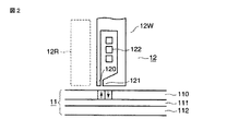
本実施形態のディスクドライブ10は、垂直磁気記録可能なディスク媒体11を使用するハードディスクドライブである。ディスク媒体11は、スピンドルモータ(SPM)13に固定されて、高速回転されるようにディスクドライブ10内に組み込まれている。ディスク媒体11は、図2に示すように、非磁性基板上に軟磁性層112、中間非磁性層111、及び垂直記録層110を積層した構成からなる。垂直記録層110は、後述するライトヘッド12Wからの垂直記録磁界に応じたデータを磁気記録する領域である。
The
ここで、ディスク媒体11上には、ライトヘッド12Wにより記録される多数のトラックが構成される。本実施形態は、後述するように、各トラック間の間隔であるトラックピッチを、ディスク媒体11上の半径位置に応じて変化させる。
Here, on the
さらに、ディスクドライブ10は、ディスク媒体11に対してデータ(サーボ情報とユーザデータ)を読出すリードヘッド12Rと、データを書き込むためのライトヘッド12Wを含む磁気ヘッド12を有する。磁気ヘッド12は、ボイスコイルモータ(VCM)15により駆動されるアクチュエータ14に搭載されている。VCM15は、VCMドライバ21により駆動電流が供給されて、駆動制御される。アクチュエータ14は、マイクロプロセッサ(CPU)19により駆動制御されて、磁気ヘッド12をディスク媒体11上の目標位置(目標トラック)に位置決めするためのヘッド移動機構である。
Further, the
このようなヘッド・ディスクアセンブリ以外に、ディスクドライブ10は、プリアンプ回路16と、信号処理回路17と、ディスクコントローラ(HDC)18と、CPU19と、メモリ20とを有する。
In addition to such a head / disk assembly, the
プリアンプ回路16は、ヘッド12のリードヘッド12Rから出力されるリードデータ信号を増幅するリードアンプ、及びライトデータ信号をライトヘッド12Wに供給するためのライトアンプを有する。信号処理回路17は、リード/ライトデータ信号(サーボ情報に対応するサーボ信号を含む)を処理する信号処理回路であり、リード/ライトチャネルとも呼ばれている。
The
HDC18は、ドライブ10とホストシステム22(例えばパーソナルコンピュータや各種のディジタル機器)とのインターフェース機能を有する。HDC18は、ディスク11とホストシステム22間のリード/ライトデータの転送制御を実行する。
The
CPU19は、ドライブ10のメインコントローラであり、ヘッド位置決め制御及びユーザデータの通常のリード/ライト動作制御を実行する。即ち、CPU19は、ディスク媒体11上に構成されるトラックのトラックピッチを可変させるために、ヘッド位置決め制御及びデータのライト動作制御を実行する具体的手段である。
The
メモリ20は、不揮発性メモリであるフラッシュメモリ(EEPROM)以外に、RAM及びROMなどを含み、CPU19の制御に必要な各種データ及びプログラムを保存する。
The
(磁気ヘッドの構造)
図2は、本実施形態に関する磁気ヘッド12の構造を説明するための図である。
(Magnetic head structure)
FIG. 2 is a diagram for explaining the structure of the
磁気ヘッド12は、ライトヘッド12Wとリードヘッド12Rとが分離して、図示しないスライダ上に実装された構造である。リードヘッド12Rは、読出し専用ヘッドであり、通常では、GMR(giant magnetoresistive)素子から構成されている。
The
ライトヘッド12Wは、垂直磁気記録に適した単磁極型ヘッドであり、主磁極(記録磁極)120と、補助磁極に相当するトレーリング(trailing)側磁極121を有するリターンヨークと、励磁コイル122とを有する。ライトヘッド12Wでは、ディスク媒体11の走行方向(図2の右方向)において、後端側にトレーリング(trailing)側磁極121が配置されて、主磁極120がリーディング・エッジ(leading edge)側に設けられている。
The
主磁極120は、相対的に透磁率の高い軟磁性材料からなり、励磁コイル122に流される記録電流に応じた垂直記録磁界を励起する。本実施形態では、後述するように、主磁極120は、ディスク媒体11の表面に対向する底面が、台形または三角形状に加工された構造である。
The main
(主磁極の構造)
以下、図3から図10を参照して、本実施形態のライトヘッド12Wにおける主磁極120の構造を説明する。
(Main pole structure)
Hereinafter, the structure of the main
図3は、本実施形態のライトヘッド12Wにおける主磁極120の構造において、ディスク媒体11の表面に対向する底面120Wを示す図である。本実施形態では、主磁極120は、底面120Wが台形の形状に加工されている。また、底面120Wの形状は、三角形状に加工されていてもよい。
FIG. 3 is a diagram showing a
ここで、主磁極120の構造に関する各パラメータを、図3(A)に示すように、底面120Wにおける上底の幅をPW、主磁極長をPT、下底の幅をPWBで表す。さらに、図3(B)に示すように、上底の幅PW、主磁極長PT、及び下底の幅PWBに基づいて、いわゆるベベル(bevel)角をBaで表す。
Here, as shown in FIG. 3A, the parameters relating to the structure of the main
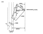
図4は、アクチュエータ14に搭載された状態において、リードヘッド12Rのリード素子120R、主磁極120の底面120W、及びディスク媒体上での位置関係を示す図である。図4において、ディスク媒体上でのライトヘッド12Wの磁気的トラック幅をMWWとし、リードヘッド12Rの磁気的リード幅をMRWとした場合、スキュ角Haが付いた状態での各パラメータの定義を示す。
FIG. 4 is a diagram showing the positional relationship between the
ここで、一般的に、磁気的トラック幅MWWと主磁極120の上底の幅PWとは、「MWW≧PW」の関係にある。また、磁気的リード幅MRWとリード素子120Rのリード幅RWとは、「MRW≧RW」の関係にある。さらに、ライトヘッド12Wの磁気的ヘッド長MTと主磁極長PTとは、「MT≧PT」の関係にある。
Here, in general, the magnetic track width MWW and the width PW of the upper base of the
図4に示すように、磁気ヘッド12にスキュ角Haが付いた状態では、磁気的トラック幅MWWに対する実効トラック幅をeMWWとし、磁気的リード幅MRWに対する実効リード幅をeMRWとする。
As shown in FIG. 4, when the skew angle Ha is attached to the
(主磁極の構造と可変トラックピッチ構成)
以上のように、本実施形態におけるライトヘッド12Wにおいて、主磁極120の底面120Wを台形または三角形状に加工し、ベベル角Baを付けた構造により、スキュ角Haが大きくなっても、後述するように、実効トラック幅が増大して、高いトラック密度を実現できる。しかし一方で、ベベル角Baを大きくすると、主磁極120の底面120Wの面積を減少させて、磁気記録能力の低下を招く。
(Main pole structure and variable track pitch configuration)
As described above, in the
そこで、本実施形態は、磁気記録能力を維持しながら、高いトラック記録密度(TPI)を実現するための可変トラックピッチ構成を提供する。 Therefore, the present embodiment provides a variable track pitch configuration for realizing high track recording density (TPI) while maintaining magnetic recording capability.
即ち、具体的には、スキュ角Haが0度のときの磁気的トラック幅MWW0、磁気的リード幅MRW0、磁気的ヘッド長MTとした場合に、トラックピッチTpは、下記式(4)に示すように設定する。

また、トラックピッチTpは、下記式(5),(6)に示すような関係を満たすように設定してもよい。
以下、図8から図10を参照して、トラックピッチTpと主磁極120の各パラメータとの関係を示す関係式の導出プロセスを説明する。
Hereinafter, with reference to FIGS. 8 to 10, a process for deriving a relational expression indicating the relationship between the track pitch Tp and each parameter of the main
まず、図8に示すように、磁気的トラック幅MWWは、スキュ角Haが0度のときの磁気的トラック幅をMWW0とした場合に、cos(Ha)から算出できる。次に、主磁極120のベベル角Baと磁気的ヘッド長MTとは、図9に示すような関係式により表すことができる。
First, as shown in FIG. 8, the magnetic track width MWW can be calculated from cos (Ha) when the magnetic track width when the skew angle Ha is 0 degree is MWW 0 . Next, the bevel angle Ba of the main
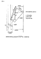
更に、図10に示すように、スキュ角Haとベベル角Baとの関係式から、実効トラック幅eMWWを算出する下記式(7)を導出できる。
![]()
![]()
また、スキュ角Haが0度のときの磁気的リード幅をMRW0とした場合に、実効リード幅eMRWをcos(Ha)との関係から、下記式(8)を導出できる。
![]()
![]()
ここで、スキュ角Haがベベル角Baより大きい場合、実効トラック幅eMWWを算出する下記式(9)を導出できる。
一方、スキュ角Haがベベル角Ba以下の場合には、主磁極120の磁極がはみ出す状態となり、当該はみ出し部分は、下記式(10)に示すものとなる。
以上のような導出プロセスにより、実効トラック幅eMWWを算出する前記式(7)を導出できる。この式(7)及び前記式(8)から、トラックピッチTpを設定するための前記式(4)を導出できる。また、前記関係式(5),(6)を導出できる。 The above formula (7) for calculating the effective track width eMWW can be derived by the derivation process as described above. From the equations (7) and (8), the equation (4) for setting the track pitch Tp can be derived. Further, the relational expressions (5) and (6) can be derived.
図5は、本実施形態を適用する各パラメータと、それに関係するトラック記録密度の具体例を説明するための図である。 FIG. 5 is a diagram for explaining a specific example of each parameter to which the present embodiment is applied and the track recording density related thereto.
図5(A)に示すように、いま仮に、目標の面記録密度(areal density)を300Gbpsiとしたときに、ディスク媒体11の半径値を15〜30mmとし、スキュ角Haを半径15mmで−13度、また半径30mmで13度で、トラック群が等間隔に20のゾーンに分かれているディスクドライブ10を想定する。
As shown in FIG. 5A, assuming that the target areal density is 300 Gbpsi, the radius value of the
このディスクドライブ10では、主磁極120の各パラメータを、PW=100nm、PT=300nm、RW=50nm、MWW=PW+30=130nm、MRW=RW=50nm、MT=PT=300nmと設定する。
In this
ここで、図6は、スキュ角(skew angle)Haと、最適なトラックピッチ(track pitch)Tpとの関係を示す。このトラックピッチTpは、前記式(4),(7),(6)に基づいて、「2Tp−eMWW−eMRW>40」の関係式から算出されたものである。図6において、実線60は、主磁極120のパラメータの一つであるベベル角Baが7度の場合の特性である。また、点線61は、ベベル角Baが9度の場合の特性である。図6に示すように、スキュ角Haが相対的の小さいディスク媒体11上の範囲では、トラックピッチTpは一定である。
Here, FIG. 6 shows the relationship between the skew angle Ha and the optimum track pitch Tp. The track pitch Tp is calculated from the relational expression “2Tp−eMWW−eMRW> 40” based on the equations (4), (7), and (6). In FIG. 6, the
図5(B)に示すように、ベベル角Baが7度の場合に、可変トラックピッチの未使用時には、同じ面容量になるように計算すると、平均線密度(kBPI)と平均トラック密度(kTPI)はそれぞれ、1459kBPI、206kTPIになる。これに対して、可変トラックピッチを使用する場合には、平均線密度(kBPI)と平均トラック密度(kTPI)はそれぞれ、1341kBPI、224kTPIとなる。 As shown in FIG. 5B, when the bevel angle Ba is 7 degrees and the variable track pitch is not used, the average line density (kBPI) and the average track density (kTPI) are calculated to obtain the same surface capacity. ) Becomes 1459 kBPI and 206 kTPI, respectively. On the other hand, when the variable track pitch is used, the average linear density (kBPI) and the average track density (kTPI) are 1341 kBPI and 224 kTPI, respectively.
同様に、ベベル角Baが9度の場合に、可変トラックピッチの未使用時には、平均線密度(kBPI)と平均トラック密度(kTPI)はそれぞれ、1397kBPI、215kTPIになる。これに対して、可変トラックピッチを使用する場合には、平均線密度(kBPI)と平均トラック密度(kTPI)はそれぞれ、1317kBPI、228kTPIとなる。即ち、可変トラックピッチを使用しない場合は線密度の差が118kBPIあるのに対して、可変トラックピッチを使用した場合は24kBPIの差のみとなる。従って、可変トラックピッチを使用した場合は、相対的に高いベベル角Baを付けなくても、高トラック密度(TPI)を達成できる。即ち、磁気ヘッド12や、ディスク媒体11の性能に大きな影響を与えずに、高記録密度を得ることができる。
Similarly, when the bevel angle Ba is 9 degrees and the variable track pitch is not used, the average linear density (kBPI) and the average track density (kTPI) are 1397 kBPI and 215 kTPI, respectively. On the other hand, when the variable track pitch is used, the average linear density (kBPI) and the average track density (kTPI) are 1317 kBPI and 228 kTPI, respectively. That is, when the variable track pitch is not used, the linear density difference is 118 kBPI, whereas when the variable track pitch is used, the difference is only 24 kBPI. Therefore, when a variable track pitch is used, a high track density (TPI) can be achieved without a relatively high bevel angle Ba. That is, a high recording density can be obtained without greatly affecting the performance of the
図7は、ベベル角Baが7度の場合において、ディスク媒体11上の半径方向におけるトラック密度(TPI)の変化を示す図である。図7において、点線71は、可変トラックピッチを使用しない場合、即ちトラックピッチが一定の場合の特性を示す。実線70は、可変トラックピッチを使用する場合の特性を示す図である。図7の実線70に示すように、相対的にスキュ角Haが小さいディスク媒体11の中周領域では、一定の高トラック密度になり、内外周領域ではトラック密度を変化させるように、トラックピッチを可変させる。
FIG. 7 is a diagram showing a change in track density (TPI) in the radial direction on the
以上のように、前記関係式(4),式(5)または(6)に基づいて、磁気ヘッド12のスキュ角Ba及び主磁極120のパラメータであるベベル角Baを考慮した可変トラックピッチTpによるトラック構成を実現する。このようなディスク媒体11上のトラック構成であれば、主磁極120の記録能力を保持している状態で、ディスク媒体11上では相対的に高いトラック密度(TPI)を達成することができる。
As described above, based on the relational expression (4), (5), or (6), the variable track pitch Tp in consideration of the skew angle Ba of the
換言すれば、垂直磁気記録において高いスキュ角Haで、高いトラック密度(TPI)を達成するために、主磁極120の底面120Wを台形または三角形状に加工し、ベベル角Baを付けた場合に、相対的に高いベベル角Baを付けなくても、ディスク媒体11上では可変トラックピッチにより高いトラック密度(TPI)を達成することができる。なお、スキュ角Haがベベル角Ba以下の場合には、トラックピッチTpは一定でよい。
In other words, in order to achieve a high track density (TPI) at a high skew angle Ha in perpendicular magnetic recording, when the
なお、本発明は上記実施形態そのままに限定されるものではなく、実施段階ではその要旨を逸脱しない範囲で構成要素を変形して具体化できる。また、上記実施形態に開示されている複数の構成要素の適宜な組み合わせにより、種々の発明を形成できる。例えば、実施形態に示される全構成要素から幾つかの構成要素を削除してもよい。さらに、異なる実施形態にわたる構成要素を適宜組み合わせてもよい。 Note that the present invention is not limited to the above-described embodiment as it is, and can be embodied by modifying the components without departing from the scope of the invention in the implementation stage. In addition, various inventions can be formed by appropriately combining a plurality of constituent elements disclosed in the embodiment. For example, some components may be deleted from all the components shown in the embodiment. Furthermore, constituent elements over different embodiments may be appropriately combined.
10…ディスクドライブ、11…ディスク媒体、12…磁気ヘッド、
12R…リードヘッド、12W…ライトヘッド、14…アクチュエータ、
19…マイクロプロセッサ(CPU)、120…主磁極、120W…底面、
Ba…ベベル(bevel)角、Ha…スキュ(skew)角。
10 ... disk drive, 11 ... disk medium, 12 ... magnetic head,
12R: Read head, 12W: Write head, 14: Actuator,
19 ... Microprocessor (CPU), 120 ... Main pole, 120W ... Bottom,
Ba ... bevel angle, Ha ... skew angle.
Claims (7)
前記ディスク媒体上から垂直磁気記録データを読出すためのリードヘッドと、前記ディスク媒体上に垂直磁気記録を行なうライトヘッドであって、前記ディスク媒体上に対向する底面が台形または三角形状である主磁極を有するライトヘッドとを含む磁気ヘッドと、
前記磁気ヘッドを搭載し、前記ディスク媒体上の半径方向に移動させるロータリ型アクチュエータとを有し、
前記ライトヘッドにより前記ディスク媒体上に記録されるトラックは、
前記ロータリ型アクチュエータにより前記ディスク媒体上に位置決めされた前記磁気ヘッドのスキュ角と前記底面でのベベル角との関係で、前記スキュ角が前記ベベル角以上となる前記ディスク媒体上の半径位置では、前記主磁極の底面のサイズ、前記スキュ角、及び前記ベベル角に基づいて設定されるトラックピッチを可変とする構成であることを特徴とするディスク記憶装置。 A disk medium capable of perpendicular magnetic recording;
A read head for reading perpendicular magnetic recording data from the disk medium, and a write head for performing perpendicular magnetic recording on the disk medium, wherein the bottom surface facing the disk medium is trapezoidal or triangular. A magnetic head including a write head having a magnetic pole;
A rotary actuator mounted with the magnetic head and moved in a radial direction on the disk medium;
Tracks recorded on the disk medium by the write head are:
In the relationship between the skew angle of the magnetic head positioned on the disk medium by the rotary actuator and the bevel angle at the bottom surface, at the radial position on the disk medium where the skew angle is equal to or greater than the bevel angle, A disk storage device characterized in that the track pitch set based on the size of the bottom surface of the main magnetic pole, the skew angle, and the bevel angle is variable.
前記ディスク媒体上から垂直磁気記録データを読出すためのリードヘッドと、
前記ディスク媒体上に垂直磁気記録を行なうライトヘッドとを有し、
前記ライトヘッドは、
前記ディスク媒体上に対向する底面が台形または三角形状である主磁極を有し、
前記ディスク媒体上に位置決めされたときのスキュ角と前記底面でのベベル角との関係で、前記スキュ角が前記ベベル角以上となる前記ディスク媒体上の半径位置では、前記ディスク媒体上に記録されるトラックが可変トラックピッチで構成される場合に、当該トラックピッチと適合する前記主磁極の底面のサイズ及び前記ベベル角が設定された構造であることを特徴とする磁気ヘッド。 A magnetic head applied to a disk storage device using a disk medium capable of perpendicular magnetic recording,
A read head for reading perpendicular magnetic recording data from the disk medium;
A write head for performing perpendicular magnetic recording on the disk medium,
The light head is
A main pole having a trapezoidal or triangular shape on the bottom surface facing the disk medium;
Due to the relationship between the skew angle when positioned on the disk medium and the bevel angle on the bottom surface, the radial angle on the disk medium where the skew angle is equal to or greater than the bevel angle is recorded on the disk medium. A magnetic head having a structure in which the size of the bottom surface of the main magnetic pole and the bevel angle matching the track pitch are set when the track is configured with a variable track pitch.
Priority Applications (4)
| Application Number | Priority Date | Filing Date | Title |
|---|---|---|---|
| JP2005342359A JP2007149223A (en) | 2005-11-28 | 2005-11-28 | Disk storage device and magnetic head |
| SG200607528-7A SG132600A1 (en) | 2005-11-28 | 2006-11-02 | Disk drive having a magnetic head for perpendicular magnetic recording |
| US11/601,785 US20070121241A1 (en) | 2005-11-28 | 2006-11-20 | Disk drive having a magnetic head for perpendicular magnetic recording |
| CNA2006101627627A CN1975862A (en) | 2005-11-28 | 2006-11-28 | Disk drive having a magnetic head for perpendicular magnetic recording |
Applications Claiming Priority (1)
| Application Number | Priority Date | Filing Date | Title |
|---|---|---|---|
| JP2005342359A JP2007149223A (en) | 2005-11-28 | 2005-11-28 | Disk storage device and magnetic head |
Publications (2)
| Publication Number | Publication Date |
|---|---|
| JP2007149223A true JP2007149223A (en) | 2007-06-14 |
| JP2007149223A5 JP2007149223A5 (en) | 2008-12-11 |
Family
ID=38087183
Family Applications (1)
| Application Number | Title | Priority Date | Filing Date |
|---|---|---|---|
| JP2005342359A Withdrawn JP2007149223A (en) | 2005-11-28 | 2005-11-28 | Disk storage device and magnetic head |
Country Status (4)
| Country | Link |
|---|---|
| US (1) | US20070121241A1 (en) |
| JP (1) | JP2007149223A (en) |
| CN (1) | CN1975862A (en) |
| SG (1) | SG132600A1 (en) |
Cited By (1)
| Publication number | Priority date | Publication date | Assignee | Title |
|---|---|---|---|---|
| US7549213B2 (en) * | 2005-01-12 | 2009-06-23 | Hitachi Global Storage Technologies Netherlands B.V. | Method for independent trackwidth and wall angle control and hexagonal write head |
Families Citing this family (2)
| Publication number | Priority date | Publication date | Assignee | Title |
|---|---|---|---|---|
| US9122397B2 (en) * | 2007-10-26 | 2015-09-01 | Emc Corporation | Exposing storage resources with differing capabilities |
| US9413825B2 (en) * | 2007-10-31 | 2016-08-09 | Emc Corporation | Managing file objects in a data storage system |
Family Cites Families (11)
| Publication number | Priority date | Publication date | Assignee | Title |
|---|---|---|---|---|
| US4945427A (en) * | 1988-06-13 | 1990-07-31 | International Business Machines Corporation | Magnetic disk recording with variable track width and variable track density |
| JPH0845189A (en) * | 1994-07-29 | 1996-02-16 | Fujitsu Ltd | Disk device and format preparing method for disk medium |
| US5680283A (en) * | 1994-09-30 | 1997-10-21 | Kabushiki Kaisha Toshiba | Magnetic head and magnetic disk drive |
| US6778343B2 (en) * | 1998-03-25 | 2004-08-17 | Hitachi Global Storage Technologies Netherlands Bv | Method, apparatus and storage system having storage media with different track pitch based upon a width of a write element associated therewith |
| US6504675B1 (en) * | 2000-01-12 | 2003-01-07 | Seagate Technology Llc | Perpendicular magnetic recording heads with write pole shaped to reduce skew effects during writing |
| JP2002237142A (en) * | 2001-02-09 | 2002-08-23 | Matsushita Electric Ind Co Ltd | Magnetic memory medium, method of controlling its track pitch and magnetic recording device for this medium |
| JP4088453B2 (en) * | 2002-02-14 | 2008-05-21 | 株式会社日立グローバルストレージテクノロジーズ | Magnetic head for perpendicular recording and magnetic disk drive equipped with the same |
| JP2004094997A (en) * | 2002-08-29 | 2004-03-25 | Tdk Corp | Thin film magnetic head and its manufacturing method |
| JP3780290B2 (en) * | 2004-09-29 | 2006-05-31 | Tdk株式会社 | Magnetic recording / reproducing device |
| US6969989B1 (en) * | 2005-03-11 | 2005-11-29 | Western Digital (Fremont), Inc. | Method for characterizing a perpendicular recording head writing pole |
| JP2007293977A (en) * | 2006-04-24 | 2007-11-08 | Fujitsu Ltd | Magnetic head and magnetic disk device |
-
2005
- 2005-11-28 JP JP2005342359A patent/JP2007149223A/en not_active Withdrawn
-
2006
- 2006-11-02 SG SG200607528-7A patent/SG132600A1/en unknown
- 2006-11-20 US US11/601,785 patent/US20070121241A1/en not_active Abandoned
- 2006-11-28 CN CNA2006101627627A patent/CN1975862A/en active Pending
Cited By (1)
| Publication number | Priority date | Publication date | Assignee | Title |
|---|---|---|---|---|
| US7549213B2 (en) * | 2005-01-12 | 2009-06-23 | Hitachi Global Storage Technologies Netherlands B.V. | Method for independent trackwidth and wall angle control and hexagonal write head |
Also Published As
| Publication number | Publication date |
|---|---|
| CN1975862A (en) | 2007-06-06 |
| SG132600A1 (en) | 2007-06-28 |
| US20070121241A1 (en) | 2007-05-31 |
Similar Documents
| Publication | Publication Date | Title |
|---|---|---|
| JP5023204B2 (en) | Magnetic recording device | |
| US8339735B2 (en) | Magnetic writer for patterned stack with increased write field | |
| JP4869418B2 (en) | Magnetic recording apparatus and magnetic recording method | |
| US7564650B2 (en) | Head apparatus having a slider with first and second positive pressure parts and a negative pressure part and disc drive having the same | |
| JP2006099852A (en) | Magnetic recording and reproducing device | |
| JP2006244550A (en) | Recording medium driving device, head position detecting method and clock signal generating method | |
| JP2005078702A (en) | Servo writing method of perpendicular magnetic recording method, and disk drive | |
| US9013966B1 (en) | Magnetic recording head and disk device including the same | |
| JP2007149223A (en) | Disk storage device and magnetic head | |
| US8804282B1 (en) | Magnetic write head having a hybrid material main pole for high frequency recording | |
| JP6382713B2 (en) | Magnetic recording / reproducing device | |
| US7796359B2 (en) | Magnetic head for perpendicular magnetic recording and method of manufacturing the same, the magnetic head including pole layer and two shields sandwiching the pole layer | |
| US6972923B2 (en) | Magnetic recording medium and magnetic recording/reproducing apparatus using the same | |
| US8593749B2 (en) | Hard-disk drive including fly-height-adjustment heating element and position-adjustment heating element and method of controlling fly height | |
| JP2009181641A (en) | Magnetic recording head, composite thin film magnetic head, and magnetic disk device | |
| US7099104B2 (en) | Method for servo writing and disk drive with servo control system | |
| EP1944762A2 (en) | Magnetic disk device | |
| US20060221491A1 (en) | Head position calculation method in magnetic disc apparatus | |
| US20140362468A1 (en) | Magnetic recording head and disk drive with the same | |
| JP4099180B2 (en) | Magnetic recording / reproducing device | |
| US20050174671A1 (en) | Method to increase the amount of customer data on a hard disk drive | |
| JP2008204502A (en) | Positioning method of writing head | |
| JP4236144B2 (en) | Magnetic recording apparatus and method | |
| JP2008059716A (en) | Magnetic recording and reproducing device, magnetic recording head device and magnetic recording method | |
| US20170092301A1 (en) | Shingle magnetic writer having nonconformal shields |
Legal Events
| Date | Code | Title | Description |
|---|---|---|---|
| A521 | Written amendment |
Free format text: JAPANESE INTERMEDIATE CODE: A523 Effective date: 20081027 |
|
| A621 | Written request for application examination |
Free format text: JAPANESE INTERMEDIATE CODE: A621 Effective date: 20081027 |
|
| A761 | Written withdrawal of application |
Free format text: JAPANESE INTERMEDIATE CODE: A761 Effective date: 20090909 |