JP4086591B2 - Fuel tank sub tank - Google Patents
Fuel tank sub tank Download PDFInfo
- Publication number
- JP4086591B2 JP4086591B2 JP2002251430A JP2002251430A JP4086591B2 JP 4086591 B2 JP4086591 B2 JP 4086591B2 JP 2002251430 A JP2002251430 A JP 2002251430A JP 2002251430 A JP2002251430 A JP 2002251430A JP 4086591 B2 JP4086591 B2 JP 4086591B2
- Authority
- JP
- Japan
- Prior art keywords
- tank
- rib
- fuel
- sub
- fuel tank
- Prior art date
- Legal status (The legal status is an assumption and is not a legal conclusion. Google has not performed a legal analysis and makes no representation as to the accuracy of the status listed.)
- Expired - Fee Related
Links
Images


Description
【0001】
【発明の属する技術分野】
本発明は、樹脂製の燃料タンク内部に配設される燃料タンクのサブタンクに関し、詳しくは車体の傾き時におけるサブタンク内部の燃料のこぼれが防止され、燃料タンクの組み付けに干渉せず、燃料タンクに過大な外力が加わった際も燃料タンクの過大な変形が防止される燃料タンクのサブタンクに関する。
【0002】
【従来の技術】
従来より、自動車の燃料タンクは金属や樹脂等の種々の材料で形成されている。このうち樹脂材料で形成された燃料タンクは、その内部に強度の向上を目的とした種々の形状の補強リブが設けられている。また、これら補強リブを種々の形状に形成することで、種々の機能を付加することが為されている。このような機能が付加された補強リブとしては、例えば特開平11−254978号公報に開示されるような樹脂製フューエルサブタンクがある。
【0003】
特開平11−254978号公報に開示される樹脂製フューエルサブタンク(以下、サブタンクとする)は、燃料タンク内に配設される略筒状の形状を有するものであって、このサブタンク内にはエンジンに燃料を供給するための燃料ポンプが配設される。このサブタンク内には、燃料タンク内の燃料残余量が少なくなったときに車体が傾いた場合でも燃料が保持されるため、同じくサブタンク内に配設される燃料ポンプにタンク内の燃料を確実に供給することが可能となる。
【0004】
このような燃料タンクのサブタンクは、車両が傾いた場合にその内部に良好に燃料を保持するための種々の形状が考案されている。例えば、USP4526286には、燃料タンクの上側タンク壁および下側タンク壁の対向する一部分をタンク内部に突出させ、この各々の突出部を溶着等の方法で接触点にて接触させて内部空間を形成し、この内部空間よりサブタンクを構成することが開示されている。このサブタンクによると、各々の突出部がサブタンクと燃料タンクを遮断する液漏れ防止壁となるため、車体傾斜時や急制動時等においても燃料がサブタンク内より漏れだすことが抑制される。
【0005】
ここで、樹脂製の燃料タンクは通常ブロー成形によって一体的に形成されるものである。しかし、燃料タンクをブロー成形で一体的に形成する場合、その内部形状は自ずと制限されるものであり、例えば種々の形状の補強リブを所望の位置に形成することは極めて困難であった。また、ブロー成形で得られた成型品は比較的厚肉のものであるため、車両の燃費向上の観点からも薄肉に形成された軽量の燃料タンクが望まれている。このため、例えば射出成形やプレス成形等の方法でアッパタンクとロアタンクと別々に形成し、このアッパタンクとロアタンクとを気密に一体化し燃料タンクを形成することで、種々の内部構造を良好に形成しうる薄肉の燃料タンクが考案されている。
【0006】
しかし、射出成形等でアッパタンクとロアタンクとを別々に形成する場合、上述したUSP4526286に記載されるような形状の液漏れ防止壁をアッパタンクとロアタンクとにそれぞれ分割して設けると、対向する液漏れ防止壁同士がアッパタンクとロアタンクとの組付けの際に互いに干渉して良好な一体化ができない場合があり、成形に非常に高い精度を要する場合がある。また、液漏れ防止壁同士が互いに干渉する場合、一体化する際に各々の液漏れ防止壁が破損する場合や、液漏れ防止壁と当接する燃料タンク本体に応力が集中する場合がある。
【0007】
【発明が解決しようとする課題】
本発明は上記事情を考慮してなされたもので、樹脂製の燃料タンクのサブタンクを提供することを目的とする。
【0008】
【課題を解決するための手段】
前記課題を解決する本発明の燃料タンクのサブタンクは、アッパタンクとロアタンクとが気密に一体化されてなる樹脂製の燃料タンクの内部に配設され、該アッパタンクまたはロアタンクに一体形成された補強リブの少なくとも一部から構成される燃料タンクのサブタンクであって、該サブタンクは、前記ロアタンクの底面から上方に突出する略筒状のタンクリブと、該タンクリブと対向する前記アッパタンクの表面から下方に突出するこぼれ防止壁とからなり、該こぼれ防止壁は、該タンクリブの形状と対応した形状をなし、該タンクリブに対して内周−外周方向に離間することで該タンクリブとの干渉を避けて配置され、該タンクリブの少なくとも一部に内周側あるいは外周側でオーバーラップすることを特徴とする。
【0009】
この構成によると、タンクリブとこぼれ防止壁とは周方向に離間しつつ配置されることからタンクリブとこぼれ防止壁とが干渉することがなく、アッパタンクとロアタンクとの良好な一体化が可能となるとともに、干渉によるタンクリブ,こぼれ防止壁および燃料タンク本体への応力集中が回避される。
【0010】
さらに、こぼれ防止壁がタンクリブの少なくとも一部にオーバーラップしていることから、タンクリブとこぼれ防止壁とが当接していないにも関わらずタンクリブとこぼれ防止壁とは軸方向に隙間を有さない構成となるので、傾斜時あるいは急制動時等においてもタンクリブとこぼれ防止壁との間隙から燃料が漏出することが抑制される。
【0011】
また、上記こぼれ防止壁は上記タンクリブの少なくとも一部に周方向の内周側でオーバーラップすることが好ましい。
【0012】
【発明の実施の形態】
本発明にかかる燃料タンクのサブタンクは、アッパタンクとロアタンクとが気密に一体化されてなる樹脂製の燃料タンクの内部に配設され、該アッパタンクまたはロアタンクに一体形成された補強リブの少なくとも一部から構成される燃料タンクのサブタンクである。
【0013】
上述したように、樹脂製の燃料タンクは通常ブロー成形で一体的に形成されるものであるが、本発明の燃料タンクは、射出成形などによって形成されたアッパタンクとロアタンクを一体化することで燃料タンクを形成するものである。燃料タンクをこのような構成のものとすることで、種々の形状の補強リブを燃料タンク内部に容易に形成することが可能となる。
【0014】
燃料タンクはその内部に燃料を保持するものであり、燃料は揮発しやすいものであることから、アッパタンクとロアタンクとは気密に一体化される必要がある。アッパタンクとロアタンクとを気密に一体化するためには、例えば、アッパタンクとロアタンクとの接合部位にフランジを設けてこの接合部位を広幅のものとした上で既知の手段によって一体化する方法が用いられる。この既知の一体化手段としては、例えば、溶着,接着,ボルトによる螺合等が挙げられる。アッパタンクとロアタンクとをボルトによる螺合により一体化する場合、気密性を確保するためにアッパタンクとロアタンクとの間隙にOリング等のシール材をさらに配置することが必要である。
【0015】
本発明の燃料タンクのサブタンクにおいて、アッパタンクまたはロアタンクには補強リブが一体形成されている。この補強リブの少なくとも一部が燃料タンクのサブタンクを構成する。本発明において燃料タンクは樹脂製のものであるため、金属製の燃料タンクと比較して剛性が低いものとなっている。したがって、燃料タンクの剛性を向上させるために燃料タンク内には補強リブが設けられることとなる。この補強リブは、燃料タンクのうち外力が加わる部位や応力が集中する部位等に設けることができ、アッパタンクに設けることもできるしロアタンクに設けることもできる。
【0016】
本発明の燃料タンクにおいて、サブタンクは、ロアタンクの底面から上方に突出する略筒状のタンクリブを有する。
【0017】
サブタンクは、上述したように、燃料タンク内の燃料残余量が少なくなったときに車体が傾いた場合でも燃料を良好に保持し、同じくサブタンク内に配設されるフューエルポンプにタンク内の燃料を確実に供給するものである。このサブタンクは燃料タンク内部に形成され、燃料タンクとサブタンクの内部とは通油路により一部連通している構造となっている。この通油路より燃料タンク内の燃料がサブタンク内に流入し、サブタンク内に燃料が保持されるが、サブタンクの壁面によって燃料タンクとサブタンクとは隔離される。このため、傾斜時に燃料タンク内の燃料に水位差が生じ、燃料タンク内の燃料の水位が一部非常に低いものとなった場合でもサブタンク内に保持される燃料の水位は本来の燃料タンク内の水位と近似したものとなる。したがって、傾斜時においてもサブタンク内に配設された燃料ポンプへの燃料の供給は良好におこなわれることとなる。
【0018】
このようなサブタンクの形状は、略角柱状,略円柱状,略渦巻き柱状などの種々の略筒状の形状を取ることができるが、いずれの場合にもサブタンクは少なくともその底部にてロアタンクと一体化された構造を有することとなり、このロアタンクと一体化された部分がタンクリブとなる。また本発明の燃料タンクのサブタンクにおいて、サブタンクはタンクリブと後述するこぼれ防止壁とによって構成される。したがって、サブタンクのロアタンク側部分であるタンクリブは、ロアタンクの底面から上方に突出し、上方の端側が開口して開口端部を形成する。
【0019】
本発明の燃料タンクのサブタンクにおいて、アッパタンクにはこぼれ防止壁が設けられる。こぼれ防止壁は、アッパタンクのうちタンクリブと対向する表面から下方に突出しタンクリブと周方向に離間しつつ該タンクリブの少なくとも一部にオ−バーラップする形状を有している。
【0020】
本発明の燃料タンクのサブタンクは、タンクリブがこぼれ防止壁によってオーバーラップされていることから、タンクリブの開口端部はこぼれ防止壁によって囲まれた状態となるため、サブタンクと燃料タンクとはより確実に隔離されることとなり、傾斜時にもこの開口端部より燃料がサブタンク外部に漏出することが抑制される。
【0021】
また、こぼれ防止壁は必ずしもタンクリブの全周にオーバーラップしているものである必要はない。例えば、サブタンクが燃料タンクの端部に設けられ、サブタンクと燃料タンクの壁面とが近接しているような状態の場合は、燃料タンクの壁面がこぼれ防止壁と類似の効果を発揮する場合もある。この場合は、タンクリブのうちこの部分を除く部分のみをこぼれ防止壁でオーバーラップすることも可能である。
【0022】
こぼれ防止壁の形状は、タンクリブの形状と対応した形状に形成することができる。例えばサブタンクの形状が略円柱状である場合には、サブタンクのうちロアタンクと一体化された部分であるタンクリブの形状も略円柱形となる。この場合こぼれ防止壁の形状は、タンクリブと周方向に離間しつつタンクリブをオーバーラップするために、略円柱形状のタンクリブを内周側あるいは外周側でオーバーラップする形状、すなわち、タンクリブよりやや大きいあるいはやや小さい径をもつタンクリブの形状と略類似の略円柱状に形成されるものとなる。
【0023】
また、例えばサブタンクの形状が略渦巻き柱状である場合には、タンクリブの形状もまた略渦巻き柱状となり、こぼれ防止壁の形状はこのタンクリブよりもやや大きいあるいはやや小さい径をもつタンクリブと略類似の渦巻き柱状に形成されるものとなる。こぼれ防止壁がタンクリブと周方向に離間して配置されることで、こぼれ防止壁とタンクリブとの干渉が回避され、燃料タンクの製造時の破損が抑制される。また、こぼれ防止壁とタンクリブとは当接するものではないので、成形に要する精度も比較的低いものですむ。さらに、アッパタンクとロアタンクとを一体化する際の位置決めをこのこぼれ防止壁とタンクリブとによっておこなうことができるため、燃料タンクの製造工程が容易なものとなる。
【0024】
ここで、こぼれ防止壁の高さは高いほどタンクリブをオーバーラップする部分が大きくなり、より良好なこぼれ防止効果を発揮する。そして、タンクリブの高さは高いほどより良好なこぼれ防止効果を発揮する。その一方で、例えば燃料タンクに高さ方向の外力が加わった場合、タンクリブの高さやこぼれ防止壁の高さが大きいほど、燃料タンクの高さ方向の変形がタンクリブやこぼれ防止壁によって干渉される。この場合、燃料タンクに加わる高さ方向の外力が過大なものとなると、この干渉によって燃料タンクの特定部位に応力が集中する場合があるため、燃料タンクの破損が生じるおそれがある。したがって、このタンクリブの高さおよびこぼれ防止壁の高さは、燃料タンクに加わる外力を想定し、適宜設定されるものとなる。
【0025】
本発明の燃料タンクのサブタンクにおいて、こぼれ防止壁はタンクリブの少なくとも一部に周方向の内周側でオーバーラップすることが好ましい。こぼれ防止壁がタンクリブの周方向の内周側でオーバーラップする場合、サブタンク内の燃料水位がタンクリブの高さよりも高い場合にも、タンクリブとこぼれ防止壁との間隙からの燃料の漏出がより確実に抑制される。
【0026】
さらに、こぼれ防止壁はタンクリブの周方向の外周側のみあるいは周方向の内周側のみに配置されるものに限らず、外周側と内周側との両方に配置することも可能である。この場合、タンクリブは内周側と外周側との2箇所でこぼれ防止壁によってオーバーラップされることとなり、燃料のサブタンクからの漏出はより抑制されることとなる。
【0027】
また、タンクリブの開口端部の所定位置に破断開始部を設けることもできる。破断開始部は、タンクリブの開口端部に少なくとも一つ設けられる部位であり、タンクリブの他の部分より破断しやすい形状に形成されるものである。この破断開始部は、例えば、開口端部の所定位置よりロアタンク底面方向にタンクリブの一部を切欠して形成することもできるし、開口端部の所定位置よりロアタンク底面方向に一部薄肉な部位を設けることで形成することもできるし、これに限らず既知の種々の方法を用いることもできる。
【0028】
上述したように、タンクリブの高さを大きくした方が燃料のサブタンク内部からの漏出をより抑制することができるが、一方、燃料タンクの高さ方向に外力が加わる場合には、タンクリブによって燃料タンクの変形が阻害される場合がある。タンクリブの開口端部の所定位置に破断開始部を設けることで、燃料タンクに大きな外力が作用して、燃料タンク自体が変形する際にはタンクリブの破断開始部が同時に破断する。したがって、タンクリブが燃料タンクの変形に干渉することが回避され、特定部位への応力の集中が抑制される。
【0029】
ここで開口端部の所定位置とは、タンクリブの破断が生じやすい所定位置を指す。例えばタンクリブの形状が略角柱状である場合にはこの角部を所定位置とすることが好ましく、タンクリブの形状が略円柱状である場合には等間隔あるいはランダムに選ばれた複数箇所を所定位置とすることが好ましい。いずれの場合もこの所定位置はタンクリブの破断が良好におこなわれるためには多く設けられることが好ましく、タンクリブの成型をおこない易くするとともに通常の使用状態においてサブタンクの形状を良好に保つためには少なく設けられることが好ましい。さらに、サブタンク内部からの燃料の漏出を抑制するためには、所定位置は少なく設けられることが好ましい。さらにこの場合、破断開始部を切欠して形成する場合には破断開始部はこぼれ防止壁によってオーバーラップされている部分に設けられる必要があり、短小形状に設けられることが好ましい。したがって、この所定位置は燃料タンクを形成する材料の剛性やサブタンクや燃料タンクの形状あるいはこぼれ防止壁の形状によって適宜設定され得るものである。
【0030】
また、破断開始部と対向するアッパタンクの表面には破断ガイド部を設けることができる。この破断ガイド部は燃料タンクに高さ方向の外力が加わった場合に、タンクリブを破断開始部より破断するための構造である。この破断ガイド部は破断開始部の形状と対応した形状に形成され、かつ、破断開始部より破断したタンクリブをアッパタンクと干渉しない位置に誘導可能な形状に形成されている。このため、外力が大きなものとなりタンクリブがアッパタンクに押圧される場合には破断開始部が破断ガイド部に押圧されて破断が開始する。さらに外力が過大なものとなる場合にはこの破断開始部より開始した破断が進行し、破断ガイド部によってアッパタンクと干渉しないように誘導されつつサブタンクの破断がおこなわれることとなる。
【0031】
この構成によって、燃料タンクが比較的弾性の高い樹脂材料で形成され、燃料タンク自体が容易に変形可能な構造であり、タンクリブの高さが高く形成されている場合にも、燃料タンクの高さ方向の変形をこのタンクリブが阻害することが防止される。したがって、燃料タンクの変形は良好なものとなる。
【0032】
ここで、破断部同士の干渉を防止するため、この破断ガイド部による誘導はサブタンク外方に向けておこなわれることが好ましい。また、このようなサブタンク外方に向けた破断の誘導をおこなうためには、破断ガイド部は変形時にサブタンク内部に挿入されることが望ましい。
【0033】
【実施例】
以下、本発明の実施例を添付図面を基にして説明する。
【0034】
(実施例1)
本実施例1の燃料タンクのタブタンクは、サブタンクを略角柱形状のものとし、こぼれ防止壁がタンクリブの周方向の内周側にオーバーラップする例である。本実施例1のサブタンクを有する燃料タンクの模式断面図を図1に示す。
【0035】
本実施例1のサブタンク1は、燃料タンク2の内部に配設される。燃料タンク2はアッパタンク3とロアタンク4とよりなる。アッパタンク3は樹脂を材料とし射出成形によって中空の箱状に形成された部材であり、アッパタンク3の開口部5の外周縁部には平板状のアッパフランジ部6が設けられている。ロアタンク4はアッパタンク3と同じ材料でアッパタンク3と同様の射出成形によって形成された部材であり、ロアタンク4の開口部7の外周縁部にはアッパフランジ部6と対応した平板状のロアフランジ部8が形成されている。アッパタンク3とロアタンク4とは別々に形成された後にこのアッパフランジ部6とロアフランジ部8とが溶着されて一体化されている。
【0036】
ロアタンク4の底面9にはタンクリブ10が形成されている。このタンクリブ10は、ロアタンク4の底面9より上方に延びた略角柱状の形状を有するものであり、上方の端側が開口して開口端部11を形成している。このタンクリブ10の内部の空隙には図示しない燃料ポンプが収納されている。また、タンクリブ10は図示しない通油路によって燃料タンク2と一部連通し、燃料タンク2内の燃料は、この通油路を経由してタンクリブ10の内部に流入する。
【0037】
アッパタンク3のうち、タンクリブ10と対向する位置にはアッパタンク3表面から下方に突出する形状のこぼれ防止壁12が形成されている。このこぼれ防止壁12は、タンクリブ10と周方向に離間しつつ配置され、タンクリブ10の全周にわたって周方向の内周側でオーバーラップしている。このタンクリブ10とこぼれ防止壁12とによって本発明の実施例1の燃料タンク2のサブタンク1が構成されている。
【0038】
本実施例1の燃料タンク2のサブタンク1において、タンクリブ10はその全周にわたってこぼれ防止壁12によってオーバーラップされている。したがって、車両の傾斜時や急制動時などサブタンク1内の燃料の水位がタンクリブ10を超えるような場合においても、サブタンク1内からの燃料の漏出はこぼれ防止壁12によって抑制されることとなる。
【0039】
そして、タンクリブ10とこぼれ防止壁12とは離間しつつ配置されていることから、タンクリブ10とこぼれ防止壁12とが製造時に互いに干渉することが回避される。
【0040】
(実施例2)
本実施例2の燃料タンクのタブタンクは、サブタンクが燃料タンクの端側に形成されサブタンクと燃料タンクの壁面が近接していること、こぼれ防止壁がこの近接している部分を除く部分に形成されていること以外は実施例1と同様に形成されたものである。本実施例2のサブタンクを有する燃料タンクの模式断面図を図2に示す。
【0041】
本実施例2のサブタンク13を有する燃料タンク14は、実施例1と同じ形状のアッパフランジ部15とロアフランジ部16とを有し、このアッパフランジ部15とロアフランジ部16とが実施例1と同様に溶着されることで、アッパタンク17およびロアタンク18が一体化されている。
【0042】
本実施例2において、タンクリブ19はロアタンク18の端側に燃料タンク14の壁面20と近接して実施例1と同じ形状に形成されている。また、こぼれ防止壁21は、アッパタンク17のうちタンクリブ19と対向する位置に形成されている。このこぼれ防止壁21は、タンクリブ19と周方向に離間しつつ配置され、タンクリブ19のうちロアタンク18と近接している部分以外の部分に周方向の内周側でオーバーラップしている。
【0043】
本実施例2の燃料タンク14のサブタンク13において、タンクリブ19と燃料タンク14の壁面20とは近接して形成されている。したがって、車両の傾斜時や急制動時において、サブタンク13内の燃料の水位がタンクリブ19を超えるような場合においても、サブタンク13のうち燃料タンク14の壁面20と近接している側の部分からの燃料の流出はこの燃料タンク14の壁面20によって抑制される。また、サブタンク13のうち燃料タンク14の壁面20と近接していない部分はこぼれ防止壁21によってオーバーラップされていることから、このオーバーラップされている部分のサブタンク13内からの燃料の流出はこぼれ防止壁21によって抑制されることとなる。
【0044】
(実施例3)
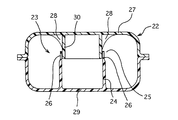
本実施例3の燃料タンクのタブタンクは、タンクリブの開口端部に破断開始部が設けられていること、破断開始部と対向するアッパタンクの表面に破断ガイド部を設けられていること以外は実施例1と同様に形成されたものである。本実施例3のサブタンクを有する燃料タンクの模式断面図を図3に示し、外力が作用した場合の本実施例3のサブタンクを有する燃料タンクの模式断面図を図4に示す。
【0045】
本実施例3の燃料タンク22のサブタンク23において、タンクリブ24の略角柱状の角部のうち開口端部側25は各々薄肉に形成されて破断開始部26を構成している。また、アッパタンク27のうち、タンクリブ24の破断開始部26と対向する表面には破断ガイド部28が形成されている。破断ガイド部28は、破断開始部26方向に突出しロアタンク29側よりもアッパタンク27側が湾曲しつつ開いた形状の略4角錐形が底面と平行な平面で切断された形状を有する。また、この破断ガイド部28はこぼれ防止壁30の周方向の外周側に配置されている。
【0046】
本実施例3の燃料タンク22のサブタンク23において、ロアタンク29の底部31よりアッパタンク27方向に外力が作用すると、ロアタンク29がアッパタンク27方向に押圧されて変形する。このとき、ロアタンク29内のタンクリブ24はアッパタンク27方向に押圧される。したがってアッパタンク27に形成されている破断ガイド部28はこのタンクリブ24内部に挿入され、タンクリブ24の破断開始部26が破断ガイド部28に当接する。破断ガイド部28のうちアッパタンク27側はロアタンク29側よりも開いた形状になっているため、外力が過大になり破断ガイド部28のサブタンク23内への挿入が進行すると、図4に示すようにタンクリブ24の開口端部側25は強制的に開かれることとなり、破断開始部26よりタンクリブ24の破断が生じる。一方、破断ガイド部28のガイド面32もまたロアタンク29側よりもアッパタンク27側が開いた、湾曲した形状となっているため、タンクリブ24の側面はこのガイド面32の湾曲した形状に即した形状に規制されて、アッパタンク27と干渉しない位置に誘導される。このように破断とガイドとが同時におこなわれることでタンクリブ24はアッパタンク27と干渉しないように誘導されつつ破断することとなる。したがって、燃料タンク22に過大な外力が作用し燃料タンク22が変形した場合にも、タンクリブ24がアッパタンク27およびロアタンク29の変形に干渉することが防止され、かつ、サブタンク23がアッパタンク27の外殻に干渉することが回避されてアッパタンク27およびロアタンク29に過大な外力が作用することが防止される。
【0047】
さらに、本実施例3の燃料タンク22のサブタンク23は実施例1と同様にタンクリブ24がこぼれ防止壁30によってオーバーラップされていることから、サブタンク23内部からの燃料の漏出は抑制される。さらに、タンクリブ24とこぼれ防止壁30とは離間しつつ配置されていることから、タンクリブ24とこぼれ防止壁30とが互いに干渉することが回避される。
【0048】
【発明の効果】
以上述べてきたように、本発明の燃料タンクのサブタンクによると、タンクリブがこぼれ防止壁によってオーバーラップされていることから、車両の傾斜時や急制動時などのサブタンク内の燃料の水位がタンクリブの高さを超えるような場合においても、サブタンク内からの燃料の漏出が抑制される。
【0049】
また、ロアタンクに形成されたタンクリブとアッパタンクに形成されたこぼれ防止壁とは周方向に離間しつつ配置されていることから、アッパタンクとロアタンクとを組付して一体化する場合においても、タンクリブとアッパタンクとの当接が回避され、製造時の燃料タンクの破損が抑制される。さらに、タンクリブとこぼれ防止壁とは当接するものではないことから、このタンクリブおよびこぼれ防止壁の成形は非常に高い精度を要するものではない。したがって、燃料タンクの成形を容易におこなうことが可能となり、製造に要する工数やコストを低減させることが可能となる。
【図面の簡単な説明】
【図1】本発明の実施例1のサブタンクを有する燃料タンクの模式断面図である。
【図2】本発明の実施例2のサブタンクを有する燃料タンクの模式断面図である。
【図3】本発明の実施例3のサブタンクを有する燃料タンクの模式断面図である。
【図4】外力が作用した場合の本発明の実施例3のサブタンクを有する燃料タンクの模式断面図である。
【符号の説明】
1:サブタンク 2:燃料タンク 3:アッパタンク 4:ロアタンク 6:アッパフランジ部 8:ロアフランジ部 10:タンクリブ 11:開口端部 12:こぼれ防止壁
13:サブタンク 14:燃料タンク 15:アッパフランジ部 16:ロアフランジ部 17:アッパタンク 18:ロアタンク 19:タンクリブ 21:こぼれ防止壁
22:燃料タンク 23:サブタンク 24:タンクリブ 25:開口端部 26:破断開始部 27:アッパタンク 28:破断ガイド部 29:ロアタンク30:こぼれ防止壁[0001]
BACKGROUND OF THE INVENTION
The present invention relates to a subtank of a fuel tank disposed inside a resin fuel tank. More specifically, fuel spillage inside the subtank when the vehicle body is tilted is prevented, and does not interfere with the assembly of the fuel tank. The present invention relates to a sub tank of a fuel tank that prevents excessive deformation of the fuel tank even when an excessive external force is applied.
[0002]
[Prior art]
Conventionally, a fuel tank of an automobile is formed of various materials such as metal and resin. Of these, the fuel tank made of a resin material is provided with reinforcing ribs of various shapes for the purpose of improving the strength. Moreover, various functions are added by forming these reinforcing ribs in various shapes. As a reinforcing rib to which such a function is added, for example, there is a resin fuel sub-tank as disclosed in JP-A-11-254978.
[0003]
A resin fuel subtank (hereinafter referred to as a subtank) disclosed in Japanese Patent Application Laid-Open No. 11-254978 has a substantially cylindrical shape disposed in a fuel tank, and an engine is disposed in the subtank. A fuel pump for supplying fuel is disposed. In this sub tank, the fuel is retained even when the vehicle body is tilted when the remaining fuel amount in the fuel tank is reduced. Therefore, the fuel in the tank is also surely supplied to the fuel pump disposed in the sub tank. It becomes possible to supply.
[0004]
Various shapes have been devised for the sub-tank of such a fuel tank in order to satisfactorily hold the fuel inside the vehicle when the vehicle is tilted. For example, US Pat. No. 4,526,286 discloses that a part of the upper tank wall and the lower tank wall of the fuel tank that are opposed to each other protrudes into the tank, and that each protruding part is contacted at a contact point by a method such as welding to form an internal space. And it is indicated that a sub tank is constituted from this internal space. According to this sub-tank, each projecting portion serves as a liquid leakage prevention wall that shuts off the sub-tank and the fuel tank, so that fuel can be prevented from leaking out of the sub-tank even when the vehicle body is tilted or suddenly braked.
[0005]
Here, the resin fuel tank is usually formed integrally by blow molding. However, when the fuel tank is integrally formed by blow molding, its internal shape is naturally limited. For example, it is extremely difficult to form various shapes of reinforcing ribs at desired positions. In addition, since a molded product obtained by blow molding is relatively thick, a lightweight fuel tank that is thin is also desired from the viewpoint of improving the fuel efficiency of a vehicle. For this reason, for example, the upper tank and the lower tank are separately formed by a method such as injection molding or press molding, and the upper tank and the lower tank are hermetically integrated to form a fuel tank, so that various internal structures can be formed satisfactorily. A thin fuel tank has been devised.
[0006]
However, when the upper tank and the lower tank are formed separately by injection molding or the like, if the liquid leakage prevention wall having the shape as described in US Pat. No. 4,526,286 is divided into the upper tank and the lower tank, respectively, the opposing liquid leakage prevention In some cases, the walls interfere with each other when the upper tank and the lower tank are assembled, and good integration may not be possible, and molding may require very high accuracy. In addition, when the liquid leakage prevention walls interfere with each other, the liquid leakage prevention walls may be damaged when they are integrated, or stress may concentrate on the fuel tank body that contacts the liquid leakage prevention wall.
[0007]
[Problems to be solved by the invention]
The present invention has been made in view of the above circumstances, and an object thereof is to provide a sub tank of a resin fuel tank.
[0008]
[Means for Solving the Problems]
The fuel tank of the present invention that solves the above problems The sub tank is The fuel tank is a sub-tank of a fuel tank that is disposed inside a resin fuel tank in which an upper tank and a lower tank are integrated in an airtight manner and includes at least part of a reinforcing rib integrally formed with the upper tank or the lower tank. The sub tank includes a substantially cylindrical tank rib protruding upward from the bottom surface of the lower tank and a spill prevention wall protruding downward from the surface of the upper tank facing the tank rib. Form a shape corresponding to the shape of the tank rib, The tank rib is arranged so as to avoid interference with the tank rib by being spaced apart in the inner circumference-outer circumference direction, and overlaps at least a part of the tank rib on the inner circumference side or the outer circumference side.
[0009]
According to this configuration, since the tank rib and the spill prevention wall are arranged apart from each other in the circumferential direction, the tank rib and the spill prevention wall do not interfere with each other, and the upper tank and the lower tank can be well integrated. , Stress concentration on the tank rib, spill prevention wall and fuel tank body due to interference is avoided.
[0010]
Furthermore, since the spill prevention wall overlaps at least a part of the tank rib, the tank rib and the spill prevention wall have no gap in the axial direction even though the tank rib and the spill prevention wall are not in contact with each other. Due to this configuration, fuel leakage from the gap between the tank rib and the spillage prevention wall is suppressed even during inclining or sudden braking.
[0011]
Moreover, it is preferable that the spill prevention wall overlaps at least a part of the tank rib on the inner peripheral side in the circumferential direction.
[0012]
DETAILED DESCRIPTION OF THE INVENTION
A sub tank of a fuel tank according to the present invention is disposed inside a resin fuel tank in which an upper tank and a lower tank are hermetically integrated, and includes at least a part of a reinforcing rib integrally formed with the upper tank or the lower tank. It is a sub-tank of a configured fuel tank.
[0013]
As described above, the resin fuel tank is usually integrally formed by blow molding. However, the fuel tank of the present invention is formed by integrating the upper tank and the lower tank formed by injection molding or the like. It forms a tank. By using the fuel tank having such a configuration, it is possible to easily form reinforcing ribs having various shapes inside the fuel tank.
[0014]
The fuel tank holds the fuel therein, and the fuel is volatile. Therefore, the upper tank and the lower tank need to be integrated in an airtight manner. In order to integrate the upper tank and the lower tank in an airtight manner, for example, a method is used in which a flange is provided at a joint portion between the upper tank and the lower tank so that the joint portion is wide and then integrated by known means. . Examples of the known integration means include welding, adhesion, and screwing with bolts. When the upper tank and the lower tank are integrated by screwing with bolts, it is necessary to further arrange a sealing material such as an O-ring in the gap between the upper tank and the lower tank in order to ensure airtightness.
[0015]
In the sub tank of the fuel tank according to the present invention, the upper tank or the lower tank is integrally formed with a reinforcing rib. At least a part of the reinforcing rib constitutes a sub tank of the fuel tank. In the present invention, since the fuel tank is made of resin, its rigidity is lower than that of a metal fuel tank. Accordingly, reinforcing ribs are provided in the fuel tank in order to improve the rigidity of the fuel tank. The reinforcing rib can be provided in a portion of the fuel tank where an external force is applied or a portion where stress is concentrated, and can be provided in the upper tank or in the lower tank.
[0016]
In the fuel tank of the present invention, the sub tank has a substantially cylindrical tank rib protruding upward from the bottom surface of the lower tank.
[0017]
As described above, the sub-tank holds the fuel well even when the vehicle body is tilted when the remaining fuel amount in the fuel tank decreases, and the fuel in the tank is also supplied to the fuel pump disposed in the sub-tank. It is surely supplied. This sub tank is formed inside the fuel tank, and the fuel tank and the inside of the sub tank are partly connected by an oil passage. The fuel in the fuel tank flows into the sub tank through this oil passage, and the fuel is held in the sub tank, but the fuel tank and the sub tank are separated from each other by the wall surface of the sub tank. For this reason, even when the water level difference occurs in the fuel in the fuel tank at the time of inclination, and the water level of the fuel in the fuel tank becomes partly very low, the water level of the fuel held in the sub-tank remains in the original fuel tank. It is an approximation of the water level. Therefore, fuel can be supplied satisfactorily to the fuel pump disposed in the sub tank even when the vehicle is inclined.
[0018]
The shape of such a sub tank can be various substantially cylindrical shapes such as a substantially prismatic shape, a substantially cylindrical shape, and a substantially spiral column shape. In any case, the sub tank is integrated with the lower tank at least at the bottom thereof. The portion integrated with the lower tank becomes a tank rib. In the subtank of the fuel tank according to the present invention, the subtank is constituted by a tank rib and a spill prevention wall described later. Accordingly, the tank rib, which is the lower tank side portion of the sub tank, projects upward from the bottom surface of the lower tank, and the upper end side opens to form an open end.
[0019]
In the sub tank of the fuel tank according to the present invention, the upper tank is provided with a spill prevention wall. The spill prevention wall has a shape that protrudes downward from the surface of the upper tank facing the tank rib and overlaps at least a part of the tank rib while being spaced apart from the tank rib in the circumferential direction.
[0020]
In the subtank of the fuel tank of the present invention, since the tank rib is overlapped by the spill prevention wall, the opening end of the tank rib is surrounded by the spill prevention wall, so that the subtank and the fuel tank are more reliably connected. As a result, the fuel is prevented from leaking out of the sub-tank from the end of the opening even when inclined.
[0021]
Further, the spill prevention wall does not necessarily have to overlap the entire circumference of the tank rib. For example, when the sub tank is provided at the end of the fuel tank, and the sub tank and the wall surface of the fuel tank are close to each other, the wall surface of the fuel tank may exhibit the same effect as the spill prevention wall. . In this case, it is possible to overlap only the portion of the tank rib excluding this portion with the spill prevention wall.
[0022]
The shape of the spill prevention wall can be formed in a shape corresponding to the shape of the tank rib. For example, when the shape of the sub tank is a substantially cylindrical shape, the shape of the tank rib that is a portion of the sub tank integrated with the lower tank is also a substantially cylindrical shape. In this case, the shape of the spill prevention wall is such that the tank rib is overlapped on the inner peripheral side or the outer peripheral side in order to overlap the tank rib while being spaced apart from the tank rib in the circumferential direction, that is, slightly larger than the tank rib or It is formed in a substantially cylindrical shape that is substantially similar to the shape of the tank rib having a slightly smaller diameter.
[0023]
For example, when the sub tank has a substantially spiral column shape, the tank rib also has a substantially spiral column shape. It will be formed in a columnar shape. Since the spill prevention wall is spaced apart from the tank rib in the circumferential direction, interference between the spill prevention wall and the tank rib is avoided, and damage during the manufacture of the fuel tank is suppressed. Further, since the spill prevention wall and the tank rib are not in contact with each other, the accuracy required for molding can be relatively low. Further, since the positioning when the upper tank and the lower tank are integrated can be performed by the spill prevention wall and the tank rib, the manufacturing process of the fuel tank is facilitated.
[0024]
Here, the higher the height of the spill prevention wall, the larger the portion where the tank ribs overlap, and a better spill prevention effect is exhibited. And the higher the height of the tank rib, the better the spill prevention effect. On the other hand, for example, when an external force in the height direction is applied to the fuel tank, the deformation of the fuel tank in the height direction interferes with the tank rib or the spill prevention wall as the height of the tank rib or the spill prevention wall increases. . In this case, if the external force in the height direction applied to the fuel tank becomes excessive, stress may concentrate on a specific part of the fuel tank due to this interference, and the fuel tank may be damaged. Therefore, the height of the tank rib and the height of the spill prevention wall are appropriately set assuming external force applied to the fuel tank.
[0025]
In the subtank of the fuel tank of the present invention, the spill prevention wall preferably overlaps at least a part of the tank rib on the inner peripheral side in the circumferential direction. When the spill prevention wall overlaps on the inner circumferential side of the tank rib, even if the fuel level in the sub tank is higher than the tank rib height, fuel leakage from the gap between the tank rib and the spill prevention wall is more reliable. To be suppressed.
[0026]
Further, the spill prevention wall is not limited to being disposed only on the outer peripheral side in the circumferential direction of the tank rib or only on the inner peripheral side in the circumferential direction, and may be disposed on both the outer peripheral side and the inner peripheral side. In this case, the tank ribs are overlapped by the spill prevention walls at two locations, the inner peripheral side and the outer peripheral side, and the leakage of fuel from the sub tank is further suppressed.
[0027]
Moreover, a break start part can also be provided in the predetermined position of the opening edge part of a tank rib. The break start portion is a portion provided at least at the opening end of the tank rib, and is formed in a shape that is easier to break than other portions of the tank rib. The break start portion can be formed, for example, by cutting a part of the tank rib from the predetermined position of the opening end toward the lower tank bottom surface, or a part that is partially thin from the predetermined position of the opening end toward the lower tank bottom surface. However, the present invention is not limited to this, and various known methods can also be used.
[0028]
As described above, increasing the height of the tank rib can further suppress the leakage of fuel from the inside of the sub-tank. On the other hand, when an external force is applied in the height direction of the fuel tank, the fuel tank Deformation may be hindered. By providing a break start portion at a predetermined position of the opening end of the tank rib, when the fuel tank is deformed by a large external force, the break start portion of the tank rib is simultaneously broken. Therefore, the tank rib is prevented from interfering with the deformation of the fuel tank, and the concentration of stress on the specific part is suppressed.
[0029]
Here, the predetermined position of the opening end portion refers to a predetermined position where the tank rib is easily broken. For example, when the shape of the tank rib is a substantially prismatic shape, the corner is preferably set at a predetermined position. When the shape of the tank rib is a substantially columnar shape, a plurality of locations selected at equal intervals or at random are set at predetermined positions. It is preferable that In any case, it is preferable to provide a large number of the predetermined positions so that the tank rib can be ruptured satisfactorily. It is preferable to be provided. Furthermore, in order to suppress the leakage of fuel from the inside of the sub tank, it is preferable to provide a small number of predetermined positions. Further, in this case, when the break start portion is formed by cutting out, the break start portion needs to be provided in a portion overlapped by the spill prevention wall, and is preferably provided in a short shape. Therefore, the predetermined position can be appropriately set depending on the rigidity of the material forming the fuel tank, the shape of the sub tank or the fuel tank, or the shape of the spill prevention wall.
[0030]
In addition, a break guide portion can be provided on the surface of the upper tank facing the break start portion. The break guide portion is a structure for breaking the tank rib from the break starting portion when an external force in the height direction is applied to the fuel tank. The break guide portion is formed in a shape corresponding to the shape of the break start portion, and is formed in a shape that can guide the tank rib broken from the break start portion to a position that does not interfere with the upper tank. For this reason, when the external force becomes large and the tank rib is pressed against the upper tank, the break start portion is pressed against the break guide portion and the break starts. Further, when the external force becomes excessive, the rupture started from the rupture start portion proceeds, and the sub tank is ruptured while being guided by the rupture guide portion so as not to interfere with the upper tank.
[0031]
With this configuration, even when the fuel tank is formed of a resin material having a relatively high elasticity and the fuel tank itself can be easily deformed, and the height of the tank rib is high, the height of the fuel tank This tank rib is prevented from obstructing the directional deformation. Therefore, the deformation of the fuel tank is good.
[0032]
Here, in order to prevent interference between the rupture portions, the guidance by the rupture guide portion is preferably performed outward of the sub tank. Further, in order to induce such a break toward the outside of the sub tank, it is desirable that the break guide portion is inserted into the sub tank at the time of deformation.
[0033]
【Example】
Embodiments of the present invention will be described below with reference to the accompanying drawings.
[0034]
Example 1
The tub tank of the fuel tank according to the first embodiment is an example in which the sub tank has a substantially prismatic shape, and the spill prevention wall overlaps the inner peripheral side in the circumferential direction of the tank rib. A schematic cross-sectional view of a fuel tank having a sub-tank of the first embodiment is shown in FIG.
[0035]
The sub tank 1 according to the first embodiment is disposed inside the
[0036]
A
[0037]
In the
[0038]
In the sub tank 1 of the
[0039]
Since the
[0040]
(Example 2)
The tub tank of the fuel tank according to the second embodiment is formed such that the sub tank is formed on the end side of the fuel tank, the wall surface of the sub tank and the fuel tank are close to each other, and the spill prevention wall is formed in a portion other than the adjacent portion. Except for this, it was formed in the same manner as in Example 1. A schematic cross-sectional view of a fuel tank having a sub-tank of the second embodiment is shown in FIG.
[0041]
The
[0042]
In the second embodiment, the
[0043]
In the
[0044]
(Example 3)
The tub tank of the fuel tank according to the third embodiment is the same as the first embodiment except that a break start portion is provided at the opening end of the tank rib and a break guide portion is provided on the surface of the upper tank facing the break start portion. 1 is formed. FIG. 3 shows a schematic cross-sectional view of the fuel tank having the sub-tank of the third embodiment, and FIG. 4 shows a schematic cross-sectional view of the fuel tank having the sub-tank of the third embodiment when an external force is applied.
[0045]
In the sub-tank 23 of the
[0046]
In the
[0047]
Further, in the
[0048]
【The invention's effect】
As described above, according to the subtank of the fuel tank of the present invention, since the tank rib is overlapped by the spill prevention wall, the water level of the fuel in the subtank when the vehicle is tilted or suddenly braked, etc. Even when the height is exceeded, fuel leakage from the sub-tank is suppressed.
[0049]
In addition, since the tank rib formed in the lower tank and the spill prevention wall formed in the upper tank are arranged apart from each other in the circumferential direction, even when the upper tank and the lower tank are assembled and integrated, Contact with the upper tank is avoided, and damage to the fuel tank during manufacturing is suppressed. Furthermore, since the tank rib and the spill prevention wall are not in contact with each other, the molding of the tank rib and the spill prevention wall does not require very high accuracy. Therefore, the fuel tank can be easily molded, and the man-hours and costs required for manufacturing can be reduced.
[Brief description of the drawings]
FIG. 1 is a schematic cross-sectional view of a fuel tank having a sub tank according to a first embodiment of the present invention.
FIG. 2 is a schematic cross-sectional view of a fuel tank having a sub tank according to a second embodiment of the present invention.
FIG. 3 is a schematic cross-sectional view of a fuel tank having a sub tank according to a third embodiment of the present invention.
FIG. 4 is a schematic cross-sectional view of a fuel tank having a sub tank according to a third embodiment of the present invention when an external force is applied.
[Explanation of symbols]
1: Sub tank 2: Fuel tank 3: Upper tank 4: Lower tank 6: Upper flange 8: Lower flange 10: Tank rib 11: Open end 12: Spill prevention wall
13: Sub tank 14: Fuel tank 15: Upper flange portion 16: Lower flange portion 17: Upper tank 18: Lower tank 19: Tank rib 21: Spill prevention wall
22: Fuel tank 23: Sub tank 24: Tank rib 25: Open end 26: Breaking start part 27: Upper tank 28: Breaking guide part 29: Lower tank 30: Spill prevention wall
Claims (2)
該サブタンクは、前記ロアタンクの底面から上方に突出する略筒状のタンクリブと、該タンクリブと対向する前記アッパタンクの表面から下方に突出するこぼれ防止壁とからなり、
該こぼれ防止壁は、該タンクリブの形状と対応した形状をなし、該タンクリブに対して内周−外周方向に離間することで該タンクリブとの干渉を避けて配置され、該タンクリブの少なくとも一部に内周側あるいは外周側でオーバーラップすることを特徴とする燃料タンクのサブタンク。 A sub-tank of a fuel tank that is disposed inside a resin fuel tank in which an upper tank and a lower tank are airtightly integrated, and includes at least a part of a reinforcing rib integrally formed with the upper tank or the lower tank. ,
The sub tank includes a substantially cylindrical tank rib protruding upward from the bottom surface of the lower tank and a spill prevention wall protruding downward from the surface of the upper tank facing the tank rib.
The spill prevention wall has a shape corresponding to the shape of the tank rib, and is disposed so as to avoid interference with the tank rib by being spaced apart from the tank rib in the inner circumference-outer circumference direction. A fuel tank sub-tank that overlaps on an inner peripheral side or an outer peripheral side .
Priority Applications (1)
| Application Number | Priority Date | Filing Date | Title |
|---|---|---|---|
| JP2002251430A JP4086591B2 (en) | 2002-08-29 | 2002-08-29 | Fuel tank sub tank |
Applications Claiming Priority (1)
| Application Number | Priority Date | Filing Date | Title |
|---|---|---|---|
| JP2002251430A JP4086591B2 (en) | 2002-08-29 | 2002-08-29 | Fuel tank sub tank |
Publications (2)
| Publication Number | Publication Date |
|---|---|
| JP2004090700A JP2004090700A (en) | 2004-03-25 |
| JP4086591B2 true JP4086591B2 (en) | 2008-05-14 |
Family
ID=32058014
Family Applications (1)
| Application Number | Title | Priority Date | Filing Date |
|---|---|---|---|
| JP2002251430A Expired - Fee Related JP4086591B2 (en) | 2002-08-29 | 2002-08-29 | Fuel tank sub tank |
Country Status (1)
| Country | Link |
|---|---|
| JP (1) | JP4086591B2 (en) |
Families Citing this family (5)
| Publication number | Priority date | Publication date | Assignee | Title |
|---|---|---|---|---|
| JP4192835B2 (en) * | 2004-04-28 | 2008-12-10 | 株式会社デンソー | Heat exchanger header tank |
| JP4575335B2 (en) * | 2006-06-30 | 2010-11-04 | 本田技研工業株式会社 | Fuel tank |
| WO2012127680A1 (en) * | 2011-03-24 | 2012-09-27 | 三菱電機株式会社 | Fuel supply apparatus |
| KR101973951B1 (en) * | 2011-05-25 | 2019-04-30 | 플라스틱 옴니엄 어드벤스드 이노베이션 앤드 리서치 | Fuel tank with improved creep resistance and method for manufacturing it |
| EP2543532A1 (en) | 2011-07-07 | 2013-01-09 | Inergy Automotive Systems Research (Société Anonyme) | Fuel tank with improved creep resistance and method for manufacturing it |
-
2002
- 2002-08-29 JP JP2002251430A patent/JP4086591B2/en not_active Expired - Fee Related
Also Published As
| Publication number | Publication date |
|---|---|
| JP2004090700A (en) | 2004-03-25 |
Similar Documents
| Publication | Publication Date | Title |
|---|---|---|
| US7014214B2 (en) | Resinous connector | |
| JP2008132953A (en) | Fuel door housing device | |
| KR102451978B1 (en) | Stiffness reinforcement structure for fuel tank of vehicle | |
| US10919379B2 (en) | Fuel tank | |
| US20020100759A1 (en) | Fuel tank | |
| JP4086591B2 (en) | Fuel tank sub tank | |
| US6367650B1 (en) | Fuel tank cover assembly for fuel tank | |
| US20030002997A1 (en) | Fuel supply apparatus | |
| JP2018039470A (en) | Fuel tank | |
| CN112776588A (en) | Device for reinforcing a vehicle fuel tank | |
| JP4021284B2 (en) | Fuel tank | |
| US11009147B2 (en) | Valve device for fuel tank | |
| JP4884156B2 (en) | Fuel tank filler structure | |
| CN110774890A (en) | Support column for fuel tank and fuel tank | |
| EP1197373A2 (en) | Plastic parts connected to a plastic fuel tank | |
| JP5125929B2 (en) | Fuel shut-off valve | |
| JPH11115509A (en) | Filler tube fixing structure of fuel tank for automobile | |
| JP6740195B2 (en) | Fuel inlet member | |
| JP2004359076A (en) | Fuel tank for automobile | |
| JP2020138781A (en) | tank | |
| KR100764497B1 (en) | Upper plate of fuel pump module for vehicle | |
| JP2002210310A (en) | Oil strainer | |
| JP2005199769A (en) | Coated member | |
| JP4390369B2 (en) | Fuel tank leakage prevention structure | |
| JP7246242B2 (en) | cap |
Legal Events
| Date | Code | Title | Description |
|---|---|---|---|
| A621 | Written request for application examination |
Free format text: JAPANESE INTERMEDIATE CODE: A621 Effective date: 20050127 |
|
| A711 | Notification of change in applicant |
Free format text: JAPANESE INTERMEDIATE CODE: A711 Effective date: 20050127 |
|
| A521 | Written amendment |
Free format text: JAPANESE INTERMEDIATE CODE: A821 Effective date: 20050128 |
|
| A977 | Report on retrieval |
Free format text: JAPANESE INTERMEDIATE CODE: A971007 Effective date: 20070411 |
|
| A131 | Notification of reasons for refusal |
Free format text: JAPANESE INTERMEDIATE CODE: A131 Effective date: 20070413 |
|
| A521 | Written amendment |
Free format text: JAPANESE INTERMEDIATE CODE: A523 Effective date: 20070612 |
|
| A131 | Notification of reasons for refusal |
Free format text: JAPANESE INTERMEDIATE CODE: A131 Effective date: 20070904 |
|
| A521 | Written amendment |
Free format text: JAPANESE INTERMEDIATE CODE: A523 Effective date: 20071102 |
|
| TRDD | Decision of grant or rejection written | ||
| A01 | Written decision to grant a patent or to grant a registration (utility model) |
Free format text: JAPANESE INTERMEDIATE CODE: A01 Effective date: 20080124 |
|
| A61 | First payment of annual fees (during grant procedure) |
Free format text: JAPANESE INTERMEDIATE CODE: A61 Effective date: 20080219 |
|
| FPAY | Renewal fee payment (event date is renewal date of database) |
Free format text: PAYMENT UNTIL: 20110228 Year of fee payment: 3 |
|
| R150 | Certificate of patent or registration of utility model |
Free format text: JAPANESE INTERMEDIATE CODE: R150 |
|
| S111 | Request for change of ownership or part of ownership |
Free format text: JAPANESE INTERMEDIATE CODE: R313111 |
|
| FPAY | Renewal fee payment (event date is renewal date of database) |
Free format text: PAYMENT UNTIL: 20110228 Year of fee payment: 3 |
|
| R350 | Written notification of registration of transfer |
Free format text: JAPANESE INTERMEDIATE CODE: R350 |
|
| FPAY | Renewal fee payment (event date is renewal date of database) |
Free format text: PAYMENT UNTIL: 20120229 Year of fee payment: 4 |
|
| FPAY | Renewal fee payment (event date is renewal date of database) |
Free format text: PAYMENT UNTIL: 20130228 Year of fee payment: 5 |
|
| FPAY | Renewal fee payment (event date is renewal date of database) |
Free format text: PAYMENT UNTIL: 20130228 Year of fee payment: 5 |
|
| FPAY | Renewal fee payment (event date is renewal date of database) |
Free format text: PAYMENT UNTIL: 20140228 Year of fee payment: 6 |
|
| R250 | Receipt of annual fees |
Free format text: JAPANESE INTERMEDIATE CODE: R250 |
|
| LAPS | Cancellation because of no payment of annual fees |