JP5125929B2 - Fuel shut-off valve - Google Patents
Fuel shut-off valve Download PDFInfo
- Publication number
- JP5125929B2 JP5125929B2 JP2008240287A JP2008240287A JP5125929B2 JP 5125929 B2 JP5125929 B2 JP 5125929B2 JP 2008240287 A JP2008240287 A JP 2008240287A JP 2008240287 A JP2008240287 A JP 2008240287A JP 5125929 B2 JP5125929 B2 JP 5125929B2
- Authority
- JP
- Japan
- Prior art keywords
- vent hole
- fuel
- valve
- casing
- valve chamber
- Prior art date
- Legal status (The legal status is an assumption and is not a legal conclusion. Google has not performed a legal analysis and makes no representation as to the accuracy of the status listed.)
- Active
Links
- 239000000446 fuel Substances 0.000 title claims description 60
- 239000002828 fuel tank Substances 0.000 claims description 34
- 230000002093 peripheral effect Effects 0.000 claims description 33
- 230000000994 depressogenic effect Effects 0.000 claims description 5
- 238000007667 floating Methods 0.000 claims description 3
- 238000013022 venting Methods 0.000 claims description 2
- 239000011347 resin Substances 0.000 description 28
- 229920005989 resin Polymers 0.000 description 28
- 238000002347 injection Methods 0.000 description 10
- 239000007924 injection Substances 0.000 description 10
- 238000009423 ventilation Methods 0.000 description 10
- 238000005452 bending Methods 0.000 description 5
- 210000000078 claw Anatomy 0.000 description 5
- 239000007788 liquid Substances 0.000 description 4
- 230000015572 biosynthetic process Effects 0.000 description 3
- 230000007423 decrease Effects 0.000 description 2
- 238000010586 diagram Methods 0.000 description 2
- 238000003780 insertion Methods 0.000 description 2
- 230000037431 insertion Effects 0.000 description 2
- 230000013011 mating Effects 0.000 description 2
- 238000000465 moulding Methods 0.000 description 2
- 238000003466 welding Methods 0.000 description 2
- 239000004698 Polyethylene Substances 0.000 description 1
- 238000013459 approach Methods 0.000 description 1
- 230000008859 change Effects 0.000 description 1
- 238000004891 communication Methods 0.000 description 1
- 239000000805 composite resin Substances 0.000 description 1
- 238000001816 cooling Methods 0.000 description 1
- 125000004122 cyclic group Chemical group 0.000 description 1
- 230000000694 effects Effects 0.000 description 1
- 230000001771 impaired effect Effects 0.000 description 1
- 230000006872 improvement Effects 0.000 description 1
- 239000000463 material Substances 0.000 description 1
- 239000002184 metal Substances 0.000 description 1
- 238000012986 modification Methods 0.000 description 1
- 230000004048 modification Effects 0.000 description 1
- -1 polyethylene Polymers 0.000 description 1
- 229920000573 polyethylene Polymers 0.000 description 1
- 230000009467 reduction Effects 0.000 description 1
- 230000004043 responsiveness Effects 0.000 description 1
- 230000000717 retained effect Effects 0.000 description 1
- 238000000926 separation method Methods 0.000 description 1
- 238000007493 shaping process Methods 0.000 description 1
- 230000001629 suppression Effects 0.000 description 1
- 239000013585 weight reducing agent Substances 0.000 description 1
Images


Classifications
-
- F—MECHANICAL ENGINEERING; LIGHTING; HEATING; WEAPONS; BLASTING
- F16—ENGINEERING ELEMENTS AND UNITS; GENERAL MEASURES FOR PRODUCING AND MAINTAINING EFFECTIVE FUNCTIONING OF MACHINES OR INSTALLATIONS; THERMAL INSULATION IN GENERAL
- F16K—VALVES; TAPS; COCKS; ACTUATING-FLOATS; DEVICES FOR VENTING OR AERATING
- F16K24/00—Devices, e.g. valves, for venting or aerating enclosures
- F16K24/04—Devices, e.g. valves, for venting or aerating enclosures for venting only
- F16K24/042—Devices, e.g. valves, for venting or aerating enclosures for venting only actuated by a float
- F16K24/044—Devices, e.g. valves, for venting or aerating enclosures for venting only actuated by a float the float being rigidly connected to the valve element, the assembly of float and valve element following a substantially translational movement when actuated, e.g. also for actuating a pilot valve
-
- Y—GENERAL TAGGING OF NEW TECHNOLOGICAL DEVELOPMENTS; GENERAL TAGGING OF CROSS-SECTIONAL TECHNOLOGIES SPANNING OVER SEVERAL SECTIONS OF THE IPC; TECHNICAL SUBJECTS COVERED BY FORMER USPC CROSS-REFERENCE ART COLLECTIONS [XRACs] AND DIGESTS
- Y10—TECHNICAL SUBJECTS COVERED BY FORMER USPC
- Y10T—TECHNICAL SUBJECTS COVERED BY FORMER US CLASSIFICATION
- Y10T137/00—Fluid handling
- Y10T137/2931—Diverse fluid containing pressure systems
- Y10T137/3003—Fluid separating traps or vents
- Y10T137/3084—Discriminating outlet for gas
- Y10T137/309—Fluid sensing valve
- Y10T137/3099—Float responsive
Description
本発明は、燃料タンクの上部に装着され接続通路を開閉することで燃料タンクと外部とを連通遮断する燃料遮断弁に関する。 The present invention relates to a fuel cutoff valve that is attached to an upper portion of a fuel tank and opens and closes a connection passage to cut off the communication between the fuel tank and the outside.
従来、タンク内の燃料蒸気をタンク外に排出するいわゆる燃料遮断弁では、車両走行中の燃料液位変化、或いは給油中の燃料液位上昇により、フロートの弁室内に燃料が入り込むとフロートにより燃料蒸気の排出を遮断する。この状態のまま給油が継続されるとタンク内圧は上昇していわゆる燃料の吹き返しを招くので、こうした吹き返し回避のため、換言すればタンク内圧の上昇回避のため、既存の燃料遮断弁では、弁室を構成するケーシングに小径の通気孔を設けることが一般的である(例えば、特許文献1)。 Conventionally, in a so-called fuel shut-off valve that discharges fuel vapor in a tank to the outside of the tank, if the fuel enters the valve chamber of the float due to a change in the fuel level while the vehicle is running or a fuel level rise during refueling, Shut off steam exhaust. If refueling is continued in this state, the internal pressure of the tank rises and so-called fuel blows back. In order to avoid such blowback, in other words, in order to avoid the rise of tank internal pressure, the existing fuel shut-off valve has a valve chamber. It is common to provide a small-diameter ventilation hole in the casing that constitutes (for example, Patent Document 1).
燃料タンクへの燃料遮断弁の装着に際しては、液密性・気密性の確保要請から、燃料遮断弁の蓋体が燃料タンクの上部壁面に熱溶着される。こうした場合、この蓋体の熱溶着に伴って溶融した樹脂(溶融樹脂)が熱溶着箇所から流れ出ることが有り得る。通常、通気孔は蓋体の側でケーシングに形成されることから、溶融樹脂が通気孔周辺に達する事が危惧される。通気孔が小径なままケーシングの弁室周壁を貫通しただけであると、溶融樹脂により小径の通気孔が閉塞されてしまい、弁室内エアの通気が損なわれることが危惧される。 When the fuel cutoff valve is attached to the fuel tank, the lid of the fuel cutoff valve is thermally welded to the upper wall surface of the fuel tank in order to ensure liquid-tightness and airtightness. In such a case, it is possible that the molten resin (molten resin) flows out from the heat-welded portion as the lid is thermally welded. Usually, since the vent hole is formed in the casing on the lid side, there is a concern that the molten resin reaches the vicinity of the vent hole. If the vent hole is only penetrated through the valve chamber peripheral wall of the casing with a small diameter, there is a concern that the small diameter vent hole is blocked by the molten resin, and the ventilation of the valve chamber air is impaired.
本発明は、上記従来の技術の問題を解決するものであり、燃料遮断弁におけるケーシングの通気孔の閉塞回避を図ることを目的とする。 SUMMARY OF THE INVENTION The present invention solves the above-described problems of the prior art, and an object thereof is to avoid obstruction of a vent hole of a casing in a fuel cutoff valve.
上記した目的の少なくとも一部を達成するために、本発明では、以下の構成を採用した。 In order to achieve at least a part of the above object, the present invention adopts the following configuration.
[適用1:燃料遮断弁]
燃料タンクの上部に装着され、燃料タンクと外部とを接続する接続通路をフロートの浮沈により開閉することで燃料タンクと外部とを連通遮断する燃料遮断弁であって、
前記燃料タンクの上部壁面に熱溶着される蓋体と、
該蓋体に固定され、前記燃料タンクと前記接続通路とを連通し前記フロートを収容する弁室を形成するケーシングとを備え、
前記ケーシングは、
前記弁室周壁の外周側に陥没形成された有底凹所の底部に、弁室内とタンク内との通気を図る通気孔を前記有底凹所の底部より小径で備える
ことを要旨とする。
[Application 1: Fuel cutoff valve]
A fuel shut-off valve that is mounted on the upper part of the fuel tank and that opens and closes a connecting passage that connects the fuel tank and the outside by floating and sinking the float and sinks the fuel tank and the outside.
A lid thermally welded to the upper wall surface of the fuel tank;
A casing that is fixed to the lid and that communicates the fuel tank and the connection passage to form a valve chamber that houses the float;
The casing is
The gist of the invention is that a bottom hole of a bottomed recess formed in a recess on the outer peripheral side of the valve chamber peripheral wall is provided with a vent hole for venting the valve chamber and the inside of the tank with a smaller diameter than the bottom of the bottomed recess.
上記構成の燃料遮断弁では、フロートを収容する弁室を有するケーシングに通気孔を有するので、この通気孔により弁室内とタンク内との通気を図る。その上で、この通気孔は、小径であるものの弁室周壁の外周側に陥没形成された有底凹所の底部に設けられている。このため、蓋体を燃料タンクの上部壁面に熱溶着する際の樹脂の溶融箇所と通気孔開口との間に有底凹所を位置させるので、溶融樹脂が溶融箇所から流れ出ても、その溶融樹脂を有底凹所に留めるようにできる。よって、通気孔により弁室内とタンク内との通気を確保した上で、燃料タンクの上部壁面への蓋体の熱溶着に伴う通気孔閉塞を回避できる。 In the fuel shut-off valve configured as described above, the casing having the valve chamber that accommodates the float has a vent hole, so that the vent hole allows the valve chamber and the tank to be ventilated. In addition, the vent hole is provided at the bottom of a bottomed recess that has a small diameter but is recessed on the outer peripheral side of the valve chamber peripheral wall. For this reason, a bottomed recess is positioned between the melted portion of the resin and the vent opening when the lid is thermally welded to the upper wall surface of the fuel tank. Resin can be retained in the bottomed recess. Therefore, it is possible to avoid the blockage of the vent hole due to the thermal welding of the lid body to the upper wall surface of the fuel tank while the vent hole ensures the ventilation between the valve chamber and the tank.
また、有底凹所の底部に小径の通気孔を有することから、次のようにも推考できる。燃料遮断弁は、蓋体やケーシング、フロート等の構成部材を、燃料タンクへの簡便な熱溶着のためばかりか軽量化のために樹脂製としており、各構成部材はそれぞれ金型にて成形される。小径の通気孔を有するケーシングにあっては、弁室形成のための芯金型の周囲にキャビティを形成するよう合わせ型を配置し、この合わせ型に通気孔形成のためのピンを設けている。通気孔が小径である都合上、通気孔形成ピンも小径となるので、ピンは、キャビティへの樹脂注入による圧力を受けて曲がりやすくなる。ピンに曲がりが起きたままであると、通気孔開口周縁にバリが残るためバリ除去が必要となり煩雑であった。バリ回避のためには、樹脂注入に際して、ピンが曲がらないよう注入圧調整する必要があり、この点でも煩雑であった。しかしながら、上記構成の燃料遮断弁では、小径の通気孔を有底凹所の底部に備えるようにすることで、有底凹所の深さ分だけ、通気孔の長さを短くできる。よって、通気孔が小径であっても、当該通気孔の形成に用いるピンを短寸とできるので、金型を用いた樹脂注入による圧力に対してのピンの耐性(耐圧性)も高まり、樹脂注入に際してのピンの曲がりを抑制できる。この結果、上記構成の燃料遮断弁によれば、通気孔開口周縁のバリの発生の抑制と注入圧調整が簡便となり、通気孔形成の簡略化を図ることができる。しかも、曲がりが抑制された短寸のピンでの通気孔形成ができることから、バリの発生も抑制され、通気孔寸法精度も高まる。よって、上記構成の燃料遮断弁によれば、高い寸法精度の通気孔を備えるために、エア通気量が安定し燃料の吹き返し等を高い実効性で回避できる。 Moreover, since it has a small-diameter ventilation hole at the bottom of the bottomed recess, it can be considered as follows. In the fuel shut-off valve, components such as lids, casings, and floats are made of resin not only for easy thermal welding to the fuel tank but also for weight reduction, and each component is molded with a mold. The In a casing having a small-diameter vent hole, a mating die is disposed so as to form a cavity around a core die for forming a valve chamber, and a pin for vent hole formation is provided in the mating die. . Because the vent hole has a small diameter, the vent hole forming pin also has a small diameter, and therefore the pin is easily bent by receiving pressure due to resin injection into the cavity. If the pin is still bent, burrs remain around the periphery of the vent hole opening, which necessitates removal of the burrs, which is complicated. In order to avoid burrs, it is necessary to adjust the injection pressure so that the pins do not bend during resin injection, which is also complicated in this respect. However, in the fuel cutoff valve configured as described above, the length of the vent hole can be shortened by the depth of the bottomed recess by providing a small diameter vent at the bottom of the bottomed recess. Therefore, even if the vent hole has a small diameter, the pin used for forming the vent hole can be made short, so that the resistance (pressure resistance) of the pin to the pressure due to resin injection using a mold is also increased, and the resin The bending of the pin during injection can be suppressed. As a result, according to the fuel cutoff valve having the above-described configuration, it is possible to easily suppress the generation of burrs at the periphery of the opening of the vent hole and to adjust the injection pressure, thereby simplifying the formation of the vent hole. In addition, since the air hole can be formed with a short pin in which bending is suppressed, the generation of burrs is also suppressed, and the air hole size accuracy is increased. Therefore, according to the fuel shut-off valve having the above-described configuration, since the air holes with high dimensional accuracy are provided, the air flow rate is stabilized, and fuel blowback or the like can be avoided with high effectiveness.
上記した燃料遮断弁は、次のような態様とすることができる。例えば、前記有底凹所の底部を、前記通気孔を取り囲む通気孔周囲部位と該通気孔周囲部位を取り囲む凹所内周壁側部位とに区画し、該凹所内周壁側部位を前記通気孔周囲部位より薄肉とすることができる。こうすれば、樹脂注入に際して、樹脂が既述した小径で且つ短寸のピンの周囲に達するに当たり、即ち通気孔周囲部位に樹脂が達するに当たり、この通気孔周囲部位の回りの薄肉の凹所内周壁側部位にて樹脂の流れを制限できる。この結果、ピン周囲に達した樹脂がピンに作用させる力を抑制できるので、ピンの曲がりはより確実に抑制され、通気孔の寸法精度の向上をもたらすことができる。 The fuel shut-off valve described above can be configured as follows. For example, the bottom of the bottomed recess is partitioned into a portion around the vent hole surrounding the vent hole and a portion around the inner peripheral wall side of the recess surrounding the vent hole surrounding portion, and the inner peripheral wall side portion of the recess is located around the vent hole portion. It can be made thinner. In this way, when the resin is injected, when the resin reaches the periphery of the small diameter and short pin as described above, that is, when the resin reaches the area around the vent hole, the inner wall of the thin recess around the area around the vent hole. Resin flow can be restricted at the side portion. As a result, the force applied to the pin by the resin that has reached the periphery of the pin can be suppressed, so that the bending of the pin can be more reliably suppressed and the dimensional accuracy of the vent hole can be improved.
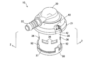
以上説明した本発明の構成・作用を一層明らかにするために、以下本発明の好適な実施例について説明する。図1は本発明の一実施の形態にかかる燃料遮断弁10の外観を示す概略斜視図、図2は図1における2−2線断面に沿って燃料遮断弁10を縦断面視して要部を示す説明図、図3は図2における3−3線に沿ってケーシング30を横断面視して要部を拡大して示す説明図である。
In order to further clarify the configuration and operation of the present invention described above, preferred embodiments of the present invention will be described below. FIG. 1 is a schematic perspective view showing the appearance of a
図示するように、燃料遮断弁10は燃料タンクFTの上部に装着される。燃料タンクFTは、その表面がポリエチレンを含む複合樹脂材料から形成されており、そのタンク上壁FTaの取付穴FTbを燃料遮断弁10の装着孔とする。取付穴FTbへの装着に当たり、燃料遮断弁10は、蓋体20の下端部21をタンク上壁FTaに熱溶着され、後述のケーシング30を燃料タンクFTの内部に位置させる。燃料遮断弁10は、車両の傾斜時や揺動時に燃料タンクFT内の燃料がキャニスタへの流出を規制すると共に、満タン液位近くまで給油された際の燃料蒸気遮断も行う。
As shown in the figure, the
燃料遮断弁10は、タンク外に位置する蓋体20と、ケーシング30と、フロート50と、スプリング60と、底蓋90とを備え、蓋体20の下端にケーシング30を固定させている。本実施例では、スプリング60を除く上記の構成材を樹脂成形品として備える。
The
蓋体20は、図示しないキャニスタからの配管の接続管部22を側方に突出して備え、接続管部22の内部から蓋体20の下方に至るまでを蓋側通路24とする。この蓋側通路24は、蓋体20のほぼ中央位置の接続通路26を経て、後述のケーシング30の弁室33と連通する。よって、接続通路26は、燃料タンクFT、詳しくはタンク内部と外部のキャニスタとを接続する。
The
ケーシング30は、上下端が解放された筒状体とされ、ケーシング天井壁31の中央に接続通路26を有し、当該通路下端縁側を環状に隆起したリップ部32とし、ケーシング天井壁31の下方空間を弁室33とする。弁室33は、燃料タンクFTの内部と接続通路26とを連通する。ケーシング30は、この弁室内周壁側に上下に延びる凸条34を等ピッチで備える。この凸条34は、弁室33の内周回りの接触面積を減らしつつフロートの浮沈動作、即ちフロートの摺動を案内する。この他、ケーシング30は、天井壁側の側から、固定用フランジ部35と、通気孔40と、有底凹所42と、周壁流入孔36と、下端開口係合部37とを備える。固定用フランジ部35は、蓋体20における下端部21の基部と接合され、レーザー照射を受けて当該基部に熱溶着される。これにより、蓋体20とケーシング30とは一体化する。周壁流入孔36は、後述の底蓋90からの燃料流入に加え、ケーシング側面の側からの燃料流入を図る。下端開口係合部37は、弁室33を閉鎖する底蓋90の係合爪92と係合し、底蓋90をケーシング30に固定する。通気孔40は、弁室33内の燃料蒸気を通気させるに足りる小径の貫通孔として弁室33の周壁に等ピッチ(本実施例では180度ピッチ)で有底凹所42と同心に形成されている。この場合、通気孔40と有底凹所42は、下端部21に熱溶着される固定用フランジ部35の下方側、即ち蓋体20とケーシング30との接合箇所側に位置している。なお、この通気孔40については、有底凹所42と合わせて後述する。
The
フロート50は、ケーシング30の弁室33に収容され、当該弁室内の燃料液位により増減する浮力を受けて浮沈し、上記した接続通路26を開閉する。なお、フロート50は本発明の要旨と直接関係しないので、概略的な構成の説明に留める。フロート50は、成形性や浮力確保の簡便化のため有底のカップ形状のアウターフロートにインナーフロートを収容して構成され、フロート上端側のシール保持部52にゴム製のシール部材54を備える。よって、後述するようにフロート50が上昇すると、シール部材54は、接続通路26の周囲のリップ部32に押し当たる際に撓み変形して接続通路26を閉鎖する。また、シール部材54は、フロート50の降下によりリップ部32から離れて接続通路26を解放するので、接続通路26を開閉する弁部として機能する。
The
底蓋90は、外周縁に等円周ピッチで4箇所の係合爪92を備え、それぞれの係合爪をケーシング30の下端開口係合部37に係合させて、ケーシング30の下端に装着される。これにより、ケーシング30の弁室33はその下端が塞がれて、フロート50の浮沈領域が形成される。また、底蓋90は、弁室33への燃料流出入を図るため、その底面に、中央貫通孔94と係合爪92の基部の貫通孔96とを備え、中央貫通孔94の周囲には、弁室33の側に隆起したスプリング受座97とフロート受座98とを備える。この両受座は、スプリング60をその外周側で受けて当該スプリングを保持し、スプリング60は、上端側のフロート50の内部まで進入させた上で、その付勢力をフロート50に及ぼす。フロート受座98は、中央貫通孔94の周囲に等ピッチで形成されて、フロート50をその下端で支える。
The
上記構成を有する本実施例の燃料遮断弁10では、燃料タンクFTに燃料が供給されて燃料液位が所定液位に達すると、弁室33の内部に、底蓋90の中央貫通孔94やケーシング30の周壁流入孔36等の貫通孔から流入した燃料により、フロート50は浮力を受けて上昇する。フロート50の上昇により、その頂上のシール部材54が接続通路26の周囲のリップ部32に当接する。これにより、接続通路26は閉鎖されるので、燃料遮断弁10は、燃料タンクFTを外部(キャニスタ)に対して遮断し、燃料タンクFTから外部への燃料流出を防止する。このフロート上昇の際には、スプリング60もフロート50に付勢力を及ぼすので、弁室33への燃料流入に伴いフロート50は速やかに上昇して、接続通路26を高い応答性で閉鎖できる。これにより、燃料タンクFTの内圧は上昇するため、給油ガンは、この圧力上昇を検知して給油を停止するので、過給油を防止できる。
In the
このような接続通路26の閉鎖状態において、フロート50には、通気孔40を経てタンク内圧が下向きに作用しているので、上記したフロート上昇に伴う接続通路26の閉鎖の後の燃料液位低下に伴う浮力低減により、フロート50は降下する。これにより、接続通路26は解放後されるので、燃料タンクFT内の燃料蒸気は、通気孔40を経て接続通路26および蓋側通路24を通過してキャニスタに達するので、タンク内圧は下がる。
In such a closed state of the
以上説明したように、本実施例の燃料遮断弁10は、弁室33における燃料液位の上昇に伴う弁室内エアのタンク内への通気を小径の通気孔40で行うが、図3に詳述するように、この通気孔40を、弁室33の外周壁30Sの側に陥没形成された有底凹所42の底部に備える。また、本実施例では、有底凹所42の底部を、通気孔40を取り囲む通気孔周囲部位40aとその周囲の凹所内周壁側部位40bとに区画し、凹所内周壁側部位40bを通気孔周囲部位40aより薄肉に形成した。このような通気孔40と有底凹所42について、その形成に用いる金型と併せて説明する。図4は通気孔40と有底凹所42の成形の際の金型の様子を示す説明図である。
As described above, the fuel shut-off
図示するように、弁室33を有するケーシング30の成形に当たっては、弁室33の形成のための芯金型CKを取り囲むようアウター側金型OKを配置して、芯金型CKの周囲にキャビティKを形成する。このアウター側金型OKは、分割金型である。次いで、アウター側金型OKに形成されたピン挿入孔PHに通気孔形成ピンPKを挿入する。この通気孔形成ピンPKは、先端に通気孔40の径と同径の先端ピンPTを備え、ピン基部を陥没部PRとし、その周囲を環状に突出した環状部POとする。このように通気孔形成ピンPKを挿入セットすると、キャビティKにおいて、通気孔形成ピンPKの先端部分である先端ピンPTと陥没部PRおよび環状部POが位置する。これにより金型セットが完了するので、キャビティKに図示しない樹脂注入口から溶融状態の樹脂を注入する。注入された樹脂は、溶融状態のままキャビティKに行き渡り、先端ピンPTの周囲へは、芯金型CKと環状部POとの間の隙間を通過した後に、芯金型CKと陥没部PRとの間に入り込んで先端ピンPTを取り囲む。この状態で冷却した後に金型を外すことで、樹脂製のケーシング30が完成し、このケーシング30は、弁室33の周壁において有底凹所42の底部に通気孔40を備え、通気孔40の周囲には、通気孔周囲部位40aとその周囲の凹所内周壁側部位40bとが形成される。
As shown in the figure, when molding the
このように形成された通気孔40は、有底凹所42の底部に位置するので、有底凹所42の深さ分だけ、短寸の通気孔となる。このため、通気孔40が小径であっても、その形成用の先端ピンPTを短寸とできるので、先端ピンPTは、図4におけるキャビティKへの樹脂注入に際しての注入圧力に対して高い耐性(耐圧性)を備えることになる。よって、樹脂注入に際して先端ピンPTの曲がり難くなるので、通気孔40の開口周縁におけるバリを抑制できると共に、樹脂の注入圧調整を簡便化できる。しかも、曲がりが抑制された短寸の先端ピンPTで形成した通気孔40を、バリ抑制に伴い高い寸法精度で形成できる。この結果、本実施例によれば、通気孔40を有底凹所42の底部に設けるという簡単な構成で、高い寸法精度でありながらその形成が簡便な通気孔40を有する新たな燃料遮断弁10を提供できる。
Since the
本実施例におけるケーシング30の肉厚と通気孔40の径等を次のようにした。ケーシング30は、約43Φの径の弁室33を備え、弁室周壁を約1.7mmとしている。通気孔40については、孔径を0.8Φとし、孔の長さを弁室周壁の約半分の0.9mmとしている。この通気孔40の孔径は、弁室内エアの通気に足りる径であれば上記寸法以外でもよく、孔の長さについては、有底凹所42の底部形成(残存)の確実性から弁室周壁の厚みの1/3〜2/3程度とすればよい。なお、燃料タンクFTのタンク容量によって燃料遮断弁10のサイズは種々変更されることから、通気孔40の径や長さ、有底凹所42の陥没径や深さにあっては、弁サイズに応じて変更すればよい。
The thickness of the
また、本実施例の燃料遮断弁10では、通気孔40を有底凹所42の底部に設けるに当たり、通気孔形成のための通気孔形成ピンPKを、小径で短寸の先端ピンPTとその基部の陥没部PRとその周囲の環状部POとを有するものとしてキャビティKに配置した。こうすることで、有底凹所42の底部を、通気孔40を取り囲む通気孔周囲部位40aと凹所内周壁側部位40bとに区画し、凹所内周壁側部位40bを通気孔周囲部位40aより薄肉とした。この結果、キャビティKに注入された樹脂は、小径で且つ短寸の先端ピンPTの周囲に達して通気孔40および通気孔周囲部位40aを形成するに当たり、芯金型CKと環状に凸の環状部POとの間の狭い隙間を通過した後に、当該隙間より広い隙間(芯金型CKと陥没部PRとの間の隙間)に達する。このため、芯金型CKと環状に凸の環状部POとの間の狭い隙間の通過の間において樹脂の流れは制限を受けるようになるので、先端ピンPTの周囲に達した樹脂がこの先端ピンPTに作用させる力は抑制される。これにより、先端ピンPTの曲がりをより確実に抑制できるので、通気孔40の寸法精度をより向上させることができる。
Further, in the
加えて、本実施例の燃料遮断弁10では、通気孔40と有底凹所42とを、蓋体20との固定対象である固定用フランジ部35の下方側、即ち蓋体20とケーシング30との係合箇所側に位置させている。よって、通気孔40は、燃料タンクFTのタンク上壁FTaに熱溶着される蓋体20の近傍となり、タンク上壁FTaにも近づくので、ケーシング30における弁室33での液位上昇時における弁室内エアのタンク内への通気確保の実効性を高めることができる。この他、次の利点がある。
In addition, in the
蓋体20をその下端部21にて燃料タンクFTのタンク上壁FTaに熱溶着する際、溶融樹脂がタンク上壁FTaの上面において熱溶着箇所から通気孔40の側に流れ出ることが有り得る。しかしながら、本実施例の燃料遮断弁10では、通気孔40のケーシング外周側開口を有底凹所42の深さ分だけ蓋体20(詳しくは下端部21)とタンク上壁FTaとの熱溶着箇所から離間させつつ、有底凹所42を溶融樹脂の溜まりとして機能させる。この結果、本実施例の燃料遮断弁10によれば、通気孔40を蓋体20の近傍として通気確保を図った上で、燃料タンクFTのタンク上壁FTaへの蓋体20の熱溶着に伴う通気孔閉塞を高い実効性で回避できる。
When the
次に参考例と変形例について説明する。図5は図3相当図であり参考例の有底凹所42Aと通気孔40の周囲を拡大して示す断面図、図6は変形例の有底凹所42Bと通気孔40の周囲を拡大して示す断面図、図7は別の参考例の有底凹所42Cと通気孔40の周囲を拡大して示す断面図である。これら参考例と変形例では、有底凹所の底部形状がそれぞれ相違する。図5の有底凹所42Aは平坦な底部に通気孔40を備える態様であり、図6の有底凹所42Bは通気孔40の周囲を湾曲状に凸とした底部を備える態様であり、図7の有底凹所42Cは通気孔40の周囲からテーパ状に広がった凹所とされた態様である。これら態様の参考例と変形例であっても、既述した通気孔40の寸法精度の向上等の効果を奏することができる。
Next to be described reference examples and strange Katachirei. Figure 5 around the cross-sectional view, FIG. 6 is a
以上、本発明の実施の形態を実施例にて説明したが、本発明は上記した実施例や変形例の実施形態に限られるものではなく、その要旨を逸脱しない範囲において種々の態様にて実施することが可能である。例えば、燃料遮断弁10を、燃料タンクFTにおいて燃料蒸気をタンク外に排出する遮断弁として説明したが、フロートの浮沈に応じて流路を開閉するものであれば、燃料タンクに限らず他の用途に用いることもできる。また、流路開閉を、接続通路26の周囲のリップ部32へのシール部材54の当接・離脱で行う構成としたが、接続通路26の末端を凹形状とした上でフロート上端を凸形状とし、通路末端の凹所へのフロート上端の凸部の入り込みと離脱により流路開閉を行う構成とすることもできる。
As mentioned above, although the embodiment of the present invention has been described in the embodiments, the present invention is not limited to the above-described embodiments and modifications, and can be implemented in various modes without departing from the gist thereof. Is possible. For example, the fuel shut-off
また、通気孔40や有底凹所42は、円形の通気孔と有底凹所とできるほか、多角形の通気孔や有底凹所、或いは非円形の異形形状の通気孔や有底凹所とすることもできる。
Further, the
10…燃料遮断弁
20…蓋体
21…下端部
22…接続管部
24…蓋側通路
26…接続通路
30…ケーシング
30S…外周壁
31…ケーシング天井壁
32…リップ部
33…弁室
34…凸条
35…固定用フランジ部
36…周壁流入孔
37…下端開口係合部
40…通気孔
40a…通気孔周囲部位
40b…凹所内周壁側部位
42、42A〜42C…有底凹所
50…フロート
52…シール保持部
54…シール部材
60…スプリング
90…底蓋
92…係合爪
94…中央貫通孔
96…貫通孔
97…スプリング受座
98…フロート受座
FT…燃料タンク
FTa…タンク上壁
FTb…取付穴
PH…ピン挿入孔
PK…通気孔形成ピン
PT…先端ピン
PO…環状部
PR…陥没部
CK…芯金型
OK…アウター側金型
K…キャビティ
DESCRIPTION OF
Claims (1)
前記燃料タンクの上部壁面に熱溶着される蓋体と、
該蓋体に固定され、前記燃料タンクと前記接続通路とを連通し前記フロートを収容する弁室を形成するケーシングとを備え、
前記ケーシングは、
前記弁室周壁の外周側に陥没形成された有底凹所の底部に、弁室内とタンク内との通気を図る通気孔を前記有底凹所の底部より小径で備え、
前記有底凹所は、前記底部を、前記通気孔を取り囲む通気孔周囲部位と該通気孔周囲部位を取り囲む凹所内周壁側部位とに区画し、該凹所内周壁側部位を前記通気孔周囲部位より薄肉としている
燃料遮断弁。 A fuel shut-off valve that is mounted on the upper part of the fuel tank and that opens and closes a connecting passage that connects the fuel tank and the outside by floating and sinking the float and sinks the fuel tank and the outside.
A lid thermally welded to the upper wall surface of the fuel tank;
A casing that is fixed to the lid and that communicates the fuel tank and the connection passage to form a valve chamber that houses the float;
The casing is
The bottom of the bottomed recess is depressed formed on the outer peripheral side of the valve chamber wall, e Bei a smaller diameter than the bottom of the vent the bottomed recess to achieve venting of the valve chamber and the tank,
The bottomed recess divides the bottom into a portion around the vent hole that surrounds the vent hole and a portion of the inner peripheral wall side of the recess that surrounds the portion around the vent hole, and the inner peripheral wall side portion of the recess is defined as a portion around the vent hole. The fuel shut-off valve is made thinner .
Priority Applications (2)
| Application Number | Priority Date | Filing Date | Title |
|---|---|---|---|
| JP2008240287A JP5125929B2 (en) | 2008-09-19 | 2008-09-19 | Fuel shut-off valve |
| US12/585,167 US8360088B2 (en) | 2008-09-19 | 2009-09-08 | Fuel cutoff valve |
Applications Claiming Priority (1)
| Application Number | Priority Date | Filing Date | Title |
|---|---|---|---|
| JP2008240287A JP5125929B2 (en) | 2008-09-19 | 2008-09-19 | Fuel shut-off valve |
Publications (2)
| Publication Number | Publication Date |
|---|---|
| JP2010071399A JP2010071399A (en) | 2010-04-02 |
| JP5125929B2 true JP5125929B2 (en) | 2013-01-23 |
Family
ID=42036579
Family Applications (1)
| Application Number | Title | Priority Date | Filing Date |
|---|---|---|---|
| JP2008240287A Active JP5125929B2 (en) | 2008-09-19 | 2008-09-19 | Fuel shut-off valve |
Country Status (2)
| Country | Link |
|---|---|
| US (1) | US8360088B2 (en) |
| JP (1) | JP5125929B2 (en) |
Families Citing this family (3)
| Publication number | Priority date | Publication date | Assignee | Title |
|---|---|---|---|---|
| JP5660070B2 (en) * | 2012-03-29 | 2015-01-28 | 豊田合成株式会社 | Fuel shut-off valve |
| US9365107B2 (en) | 2012-08-31 | 2016-06-14 | Stant Usa Corp. | Fuel tank vent apparatus |
| CN206320357U (en) | 2015-08-14 | 2017-07-11 | 达纳加拿大公司 | Check-valves for panel cooler and the heat exchanger module with the check-valves |
Family Cites Families (12)
| Publication number | Priority date | Publication date | Assignee | Title |
|---|---|---|---|---|
| US5598870A (en) * | 1994-11-01 | 1997-02-04 | Toyoda Gosei Co., Ltd. | Fuel tank device for vehicle having float valve and diaphragm valve |
| US5687756A (en) * | 1995-11-08 | 1997-11-18 | Borg-Warner Automotive, Inc. | Vehicle refueling valve |
| DE19707841B4 (en) * | 1996-03-02 | 2004-04-29 | Alfmeier Präzision AG Baugruppen und Systemlösungen | vent valve |
| US5975116A (en) * | 1996-08-07 | 1999-11-02 | Borg-Warner Automotive, Inc. | Valve having multi-piece valve housing |
| US6035883A (en) * | 1998-03-13 | 2000-03-14 | Eaton Corporation | Weldable vapor vent valve for fuel tanks |
| JP3931291B2 (en) * | 2001-11-29 | 2007-06-13 | 豊田合成株式会社 | Fuel tank fuel spill regulating device |
| US6966330B2 (en) * | 2003-08-27 | 2005-11-22 | Alfmeier Corporation | Weldring with locking arrangement for valve assembly |
| JP2006009645A (en) * | 2004-06-24 | 2006-01-12 | Toyoda Gosei Co Ltd | Fuel cutoff valve |
| JP4207875B2 (en) * | 2004-09-30 | 2009-01-14 | 豊田合成株式会社 | Fuel shut-off valve |
| JP2007092834A (en) * | 2005-09-28 | 2007-04-12 | Toyoda Gosei Co Ltd | Fuel shutting-off valve |
| JP2007276499A (en) * | 2006-04-03 | 2007-10-25 | Toyoda Gosei Co Ltd | Fuel shutoff valve |
| JP5005330B2 (en) * | 2006-12-15 | 2012-08-22 | 京三電機株式会社 | Fuel spill prevention valve |
-
2008
- 2008-09-19 JP JP2008240287A patent/JP5125929B2/en active Active
-
2009
- 2009-09-08 US US12/585,167 patent/US8360088B2/en active Active
Also Published As
| Publication number | Publication date |
|---|---|
| US8360088B2 (en) | 2013-01-29 |
| JP2010071399A (en) | 2010-04-02 |
| US20100072203A1 (en) | 2010-03-25 |
Similar Documents
| Publication | Publication Date | Title |
|---|---|---|
| JP5786788B2 (en) | Full tank control valve device | |
| US7571740B2 (en) | Fuel cutoff valve | |
| US9151256B2 (en) | Overfill prevention valve | |
| JP4074113B2 (en) | Connector for fuel tank | |
| JP2009202703A (en) | Fuel shut-off valve | |
| US6779546B2 (en) | Pressure control valve for fuel tank | |
| JP5125929B2 (en) | Fuel shut-off valve | |
| JP2016068678A (en) | Fuel shutoff valve | |
| JP5949686B2 (en) | In-tank valve unit | |
| JP2007177784A (en) | Flow channel structure for tank | |
| JP2007176336A (en) | Fuel shut-off valve | |
| US9212774B2 (en) | Connector for fuel tank | |
| JP2019143580A (en) | Fuel valve | |
| JP2011046369A (en) | Fuel shutting-off valve | |
| JP2004353518A (en) | Tank fill-up regulation valve | |
| JP5123816B2 (en) | Float valve device | |
| JP6020661B2 (en) | Full tank control valve device | |
| JP2006321468A (en) | Fuel shut-off valve | |
| JP4193782B2 (en) | Fuel shut-off valve | |
| JP2009227032A (en) | Fuel shut-off valve | |
| JP4207875B2 (en) | Fuel shut-off valve | |
| JP2006131012A (en) | Valve for fuel tank | |
| CN114599905A (en) | Valve device | |
| JP2010173397A (en) | Fuel shutoff valve | |
| JP2008274922A (en) | Fuel shut-off valve |
Legal Events
| Date | Code | Title | Description |
|---|---|---|---|
| A621 | Written request for application examination |
Free format text: JAPANESE INTERMEDIATE CODE: A621 Effective date: 20100927 |
|
| A977 | Report on retrieval |
Free format text: JAPANESE INTERMEDIATE CODE: A971007 Effective date: 20120308 |
|
| A131 | Notification of reasons for refusal |
Free format text: JAPANESE INTERMEDIATE CODE: A131 Effective date: 20120321 |
|
| A521 | Request for written amendment filed |
Free format text: JAPANESE INTERMEDIATE CODE: A523 Effective date: 20120412 |
|
| TRDD | Decision of grant or rejection written | ||
| A01 | Written decision to grant a patent or to grant a registration (utility model) |
Free format text: JAPANESE INTERMEDIATE CODE: A01 Effective date: 20121002 |
|
| A01 | Written decision to grant a patent or to grant a registration (utility model) |
Free format text: JAPANESE INTERMEDIATE CODE: A01 |
|
| A61 | First payment of annual fees (during grant procedure) |
Free format text: JAPANESE INTERMEDIATE CODE: A61 Effective date: 20121015 |
|
| R150 | Certificate of patent or registration of utility model |
Free format text: JAPANESE INTERMEDIATE CODE: R150 Ref document number: 5125929 Country of ref document: JP Free format text: JAPANESE INTERMEDIATE CODE: R150 |
|
| FPAY | Renewal fee payment (event date is renewal date of database) |
Free format text: PAYMENT UNTIL: 20151109 Year of fee payment: 3 |