JP4078077B2 - Recording element unit and recording apparatus - Google Patents
Recording element unit and recording apparatus Download PDFInfo
- Publication number
- JP4078077B2 JP4078077B2 JP2002001629A JP2002001629A JP4078077B2 JP 4078077 B2 JP4078077 B2 JP 4078077B2 JP 2002001629 A JP2002001629 A JP 2002001629A JP 2002001629 A JP2002001629 A JP 2002001629A JP 4078077 B2 JP4078077 B2 JP 4078077B2
- Authority
- JP
- Japan
- Prior art keywords
- recording element
- tape
- recording
- wiring tape
- element unit
- Prior art date
- Legal status (The legal status is an assumption and is not a legal conclusion. Google has not performed a legal analysis and makes no representation as to the accuracy of the status listed.)
- Expired - Fee Related
Links
Images


Description
【0001】
【発明の属する技術分野】
本発明は、インクジェットヘッドを構成する記録素子ユニットとこれを搭載して成る記録装置に関する。
【0002】
【従来の技術】
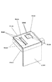
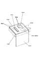
図1及び図2において、記録ヘッドH1001は、ヒーター基板の略垂直方向に液滴を吐出するサイドシュータ型であるバブルジェット方式の記録ヘッドである。この記録ヘッドH1001は、記録素子ユニットH1002とインク供給ユニットH1003とタンクホルダーH2000から成り、図1の分解斜視図に示すように、記録素子ユニットH1002は、第1の記録素子H1100、第2の記録素子H1101、第1のプレートH1200、電気配線テープH1300、電気コンタクト基板H2200、第2のプレートH1400で構成されており、又、インク供給ユニットH1003は、インク供給部材H1500、流路形成部材H1600、ジョイントゴムH2300、フィルターH1700、シールゴムH1800から構成されている。
【0003】
次に、記録素子ユニットについて説明する。
【0004】
記録素子ユニットは、第1プレートと第2プレートの接合によるプレート接合体(素子基板)の形成、記録素子のプレート接合体へのマウント、電気配線テープの積層と記録素子との電気接合、該電気接続部等の封止、の順に実装される。
【0005】
滴の吐出方向に影響するため平面精度を要求される第1のプレートH1200は、厚さ0.5〜10mmのアルミナ(Al2 O3 )材料で構成されている。第1のプレートH1200には、第1の記録素子H1100にブラックのインクを供給するためのインク供給口H1201と第2の記録素子H1101にシアン、マゼンタ、イエローのインクを供給するためのインク供給口1201が形成されている。
【0006】
第2のプレートH1400は、厚さ0.5〜1mmの1枚の板状部材であり、第1のプレートH1200に接着固定される第1の記録素子H1100と第2の記録素子H1101の外形寸法よりも大きな窓状の開口H1401を有する。第2プレートH1400は第1プレートH1200に接着剤を介して積層固定され、プレート接合体H1202を形成する。
【0007】
第1の記録素子H1100と第2の記録素子H1101は、開口H1401内に形成された第1のプレートの表面(マウント部H1203)に位置精度良く接着固定される。
【0008】
ノズル列H1104を有する記録素子H1100,H1101は、サイドシューター型バブルジェット基板として公知の構造であり、厚さ0.5〜1mmのSi基板にインク流路として長溝状の貫通口から成るインク供給口と、インク供給口を挟んだ両側にそれぞれ1列ずつ千鳥状に配列された吐出手段であるヒーター列、該ヒーター列に直交する記録素子の辺には前記ヒーターに接続され基板の両外側に接続パッドが配列された電極部を有する。
【0009】
電気配線テープ(以下、配線テープ)H1300として、TABテープが採用される。TABテープは、テープ基材(ベースフィルム)、銅箔配線、カバー層の積層体である。
【0010】
記録素子の電極部に対応するデバイスホールの2つの辺(接続辺)H1304には、接続端子としてインナーリードH1302が延出する。配線テープH1300は、カバー層の側を第2プレートの表面(テープ接着面)に熱硬化型エポキシ樹脂接着層を介して接着固定され、TABテープH1300のベースフィルムは、記録素子ユニットのキャッピング部材が当接する平滑なキャッピング面となる。
【0011】
配線テープH1300と2つの記録素子H1100,H1101は、それぞれ熱超音波圧着法や異方性導電テープを介して電気的に接続される。TABテープの場合は熱超音波圧着法によるインナーリードボンディング(ILB)が好適である。図1〜図3に示す記録素子ユニットにおいては、配線テープH1300のリードと記録素子上のスタッドバンプとがILB接合される。
【0012】
配線テープと記録素子との電気接合の後、電気接続部分をインクによる腐食や外的衝撃から保護するため、第1の封止剤H1307及び第2の封止剤H1308により封止される。第1の封止剤は、主にマウントされた記録素子の外周部を封止し、第2の封止剤は、記録素子と電極配線テープとの電気接続部の表側を封止している。
【0013】
【発明が解決しようとする課題】
平滑なキャッピング面を得るために、TABテープH1300はテープ接着面である第2プレートの表面に予め塗布された接着剤を介して圧着される。この際にTABテープとテープ接着面の間から押し出された余分な接着剤H1304はインナーリードの根元付近に流れ出し、インナーリードH1302の表面を覆いILBを阻害する。
【0014】
これを回避する方法の1つは、接続辺の近傍に押し出されてくる接着剤をトラップする溝等を設けることである。類似の構造が特開平6−198863号、特開平10−58711号公報に開示されている。
【0015】
一方、TABテープが前記溝を覆う場合は、TABテープの浮き等、弛みを防止する必要がある。これはTAB表面がインクジェットヘッド面の一部となるためで、TABテープの大きな弛みは記録装置の紙面と接触し、記録紙を汚してしまう。又、TABテープH1300の表面には、記録素子のノズルの乾燥を防ぐキャッピング部材が当接されるが、当接部におけるTABテープの弛みによるへこみはキャップリークの原因となり、キャッピング性能を低下させる。
【0016】
即ち、テープ接着面の溝や凹部をTABテープが覆う構造では、キャッピング面となるTABテープの平滑な接着が求められる。
【0017】
しかしながら、上記の課題に対する手段は、特開平6−198863号公報等には開示されていない。
【0018】
本発明は上記問題に鑑みてなされたもので、その目的とする処は、弛みのない平滑な電気配線テープの接着状態を得ることができるとともに、リークのない確実なキャッピングを行うことができる記録素子ユニット及び記録装置を提供することにある。
【0019】
【課題を解決するための手段】
上記目的を達成するため、本発明は、吐出手段を有する複数の記録素子がマウントされた素子基板上に、前記記録素子に対応したデバイスホールを有する電気配線テープを加熱接着し、該電気配線テープと前記記録素子とを電気接続した記録素子ユニットにおいて、前記電気配線テープの基材よりも線膨張率が小さい材料で構成された、前記配線テープが接着される前記素子基板のテープ接着面と、前記テープ接着面内に開口するとともに当該テープ接着面内で閉じた縁を持つ複数の凹部と、を有し、前記複数の凹部は、互いに離間する、前記記録素子がマウントされたマウント部と、前記記録素子がマウントされていないダミーマウント部と、からなり、前記電気配線テープは、前記マウント部と前記デバイスホールとが対応しつつ前記ダミーマウント部を覆うように前記テープ接着面に接着されていることを特徴とする。
【0020】
又、本発明は、上記記録素子ユニットを搭載し、前記電気配線テープに当接することによって前記記録素子を覆うキャッピング部材を有する記録装置において、前記キャッピング部材を前記電気配線テープの前記ダミーマウント部を覆う部分に触れない位置で該電気配線テープに当接させたことを特徴とする。
【0021】
【発明の実施の形態】
以下に本発明の実施の形態を添付図面に基づいて説明する。
【0022】
本実施の形態は、図3に示す従来例に対して、ダミーマウント部H1204を設けたものである。
【0023】
本実施の形態において、プレート接合体H1202(図4)を構成する第2プレートは0.6mm厚アルミナ(線膨張率=0.7×10⁻⁵)であり、従来例と同様に記録素子に対する2つの開口H1401を有するとともに、記録素子に対しない開口H1403を有する。開口H1403に対するアルミナの第1プレートの表面には第1プレートの裏面に貫通する穴H1205が設けられている。
【0024】
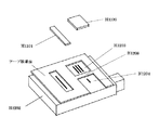
図5は本発明に係る記録素子ユニットの分解斜視図である。
【0025】
第2プレートの開口により形成された記録素子H1100に対応するマウント部H1203とダミーマウント部H1204が隣接して設けられ、それらの間にはTAABテープの接続辺付近を固定するリード支持部H1206が形成される。
【0026】
ダミーマウント部H1204は、TABテープ圧着の際に押し出された接着剤をトラップし、それらがインナーリードへ流れるのを防止する。ダミーマウント部は、接着剤の塗布量のTAB接着面内での偏りを減らすように配置されるべきである。同時に、押し出された接着剤がボンディングを阻害することがないように、TABテープの接続辺に近接する領域の接着剤の塗布量を減らすように配置されるべきである。このため、図4においては、マウント部H1203にマウントされる記録素子H1100の電極部及びそれに対応するデバイスホールH1305Rの接続辺に隣接する位置に設けられる。
【0027】
マウント部H1203には0.65mmシリコン基板から成る記録素子H1100,H1101が各々マウントされ、ダミーマウント部H1204は記録素子がマウントされない凹部として残される。
【0028】
その後、第2プレートH1400の表面に熱硬化型エポキシ接着剤が転写され、50μmポリイミド(線膨張率=1〜1.5×10⁻⁵)をベースフィルムとし2つのデバイスホールH1305R、Lを有するTABテープH1300が150℃加熱圧着される。接着剤は、加熱硬化を利用するものであれば良く、例えばUV開始型接着剤を用いてキュアを加熱により促進する工程も考えられる。
【0029】
この結果、ダミーマウント部H1204はTABテープH1300に覆われる(図6)。TABテープの熱圧着の際にダミーマウント部のエアーは貫通口H1205を通じて排出される。
【0030】
ダミーマウント部H1204をTABテープH1300で覆うことによって、インクジェットヘッドの使用中にダミーマウント部にインクや紙粉が溜まり、これらが印字中に記録紙を汚す危険を回避することができる。
【0031】
図7は図6のダミーマウント部A−A断面図である。
【0032】
ヒートツールがTABテープH1300を圧着する(図7(a))際に、接着剤が硬化するまでの間にTABテープH1300及び第2プレートH1400等は熱により膨張し、各々膨張した状態で固定される。ヒートツールが退避してワークの温度が下がると、TABテープH1300の収縮が下地(第2プレート)の収縮よりも大きく、且つ、TABテープH1300は閉じて切れ目の無い縁H1207に接着剤H1304により固定されているため、ダミーマウント部H1204上のTABテープは弛みなく支持される(図7(b))。
【0033】
一方、第2プレートをアルミニウム(線膨張率=2〜3×10⁻⁵)とし、TABテープとテープ接着面材料の線膨張の関係が逆になると、図7(c)に示すようにTABテープの好ましくない弛みが生じる。
【0034】
又、図9に示すように、ダミーマウント部H1204の縁が閉じていないと、図7(d)に示すように、TABテープの一部に弛みが生じる。
【0035】
ダミーマウント部H1204を覆うTABテープは、下地が空隙であるため、ダミーマウント部の上に硬いキャッピング手段が当接すると、TABテープが押されて弛み、キャップリークを生じる可能性がある。
【0036】
そこで、キャッピング部材が当接する場合のキャッピングの確実性を増すために、図8に示すように、ダミーマウント部H1204とキャッピング領域H3000とが重ならないようにしても良い。
【0037】
【発明の効果】
以上の説明で明らかなように、本発明によれば、接着剤をトラップするためにテープ接着面に設けられたダミーマウント部に対し、弛みのない平滑な電気配線テープの接着状態を得ることができるとともに、リークのない確実なキャッピングを行うことができる、という効果が得られる。
【図面の簡単な説明】
【図1】従来の記録素子ユニットの分解斜視図である。
【図2】従来の記録素子ユニットの分解斜視図である。
【図3】従来の記録素子ユニットの電気配線テープの斜視図である。
【図4】本発明に係る記録素子ユニットの第1及び第2プレートの斜視図である。
【図5】本発明に係る記録素子ユニットの分解斜視図である。
【図6】本発明に係る記録素子ユニットの電気配線テープの斜視図である。
【図7】本発明に係る記録素子ユニットの作用説明図である。
【図8】本発明に係る記録素子ユニットの斜視図である。
【図9】比較例に係る記録素子ユニットの斜視図である。
【符号の説明】
H1002 記録素子ユニット
H1003 インク供給ユニット
H1100 第1の記録素子
H1200 第1のプレート
H1202 プレート接合体
H1203 マウント部
H1204 ダミーマウント部
H1206 リード支持部
H1207 ダミーマウント部の縁
H1208 テープ接着面
H1300 電気配線テープ
H1304 接着剤
H1305 デバイスホール
H1306 接続辺
H1400 第2のプレート
H1401 第2プレートの開口
H1402 第2プレートの開口
H2000 タンクホルダー
H3000 キャッピング領域[0001]
BACKGROUND OF THE INVENTION
The present invention relates to a recording element unit constituting an ink jet head and a recording apparatus including the same.
[0002]
[Prior art]
1 and 2, a recording head H1001 is a bubble jet type recording head that is a side shooter type that discharges droplets in a substantially vertical direction of a heater substrate. The recording head H1001 includes a recording element unit H1002, an ink supply unit H1003, and a tank holder H2000. As shown in the exploded perspective view of FIG. 1, the recording element unit H1002 includes a first recording element H1100 and a second recording element. The ink supply unit H1003 includes an element H1101, a first plate H1200, an electric wiring tape H1300, an electric contact substrate H2200, and a second plate H1400. The ink supply unit H1003 includes an ink supply member H1500, a flow path forming member H1600, and a joint. It is composed of rubber H2300, filter H1700, and seal rubber H1800.
[0003]
Next, the recording element unit will be described.
[0004]
The recording element unit includes a plate joined body (element substrate) formed by joining a first plate and a second plate, mounting the recording element to the plate joined body, stacking of electric wiring tape and electrical joining between the recording elements, It is mounted in the order of sealing of the connection portion and the like.
[0005]
The first plate H1200, which is required to have planar accuracy because it affects the droplet ejection direction, is made of an alumina (Al 2 O 3 ) material having a thickness of 0.5 to 10 mm. The first plate H1200 has an ink supply port H1201 for supplying black ink to the first recording element H1100 and an ink supply port for supplying cyan, magenta, and yellow ink to the second recording element H1101. 1201 is formed.
[0006]
The second plate H1400 is a single plate-like member having a thickness of 0.5 to 1 mm, and the outer dimensions of the first recording element H1100 and the second recording element H1101 that are bonded and fixed to the first plate H1200. It has a larger window-like opening H1401. The second plate H1400 is laminated and fixed to the first plate H1200 via an adhesive to form a plate assembly H1202.
[0007]
The first recording element H1100 and the second recording element H1101 are bonded and fixed to the surface (mount portion H1203) of the first plate formed in the opening H1401 with high positional accuracy.
[0008]
The recording elements H1100 and H1101 having the nozzle row H1104 have a known structure as a side shooter type bubble jet substrate, and an ink supply port comprising a long groove-like through-hole as an ink channel on a Si substrate having a thickness of 0.5 to 1 mm. And a heater array as ejection means arranged in a zigzag pattern on each side across the ink supply port, and the side of the recording element perpendicular to the heater array is connected to the heater and connected to both outer sides of the substrate It has an electrode part in which a pad is arranged.
[0009]
A TAB tape is employed as the electrical wiring tape (hereinafter referred to as wiring tape) H1300. A TAB tape is a laminate of a tape substrate (base film), a copper foil wiring, and a cover layer.
[0010]
Inner leads H1302 extend as connection terminals on two sides (connection sides) H1304 of the device hole corresponding to the electrode portion of the recording element. The wiring tape H1300 has the cover layer side bonded and fixed to the surface (tape bonding surface) of the second plate via a thermosetting epoxy resin bonding layer. The base film of the TAB tape H1300 is a capping member of the recording element unit. It becomes a smooth capping surface that comes into contact.
[0011]
The wiring tape H1300 and the two recording elements H1100 and H1101 are electrically connected to each other via a thermosonic bonding method or an anisotropic conductive tape. In the case of a TAB tape, inner lead bonding (ILB) by a thermosonic bonding method is suitable. In the recording element unit shown in FIGS. 1 to 3, the lead of the wiring tape H1300 and the stud bump on the recording element are ILB bonded.
[0012]
After the electrical connection between the wiring tape and the recording element, the electrical connection portion is sealed with a first sealant H1307 and a second sealant H1308 in order to protect the electrical connection portion from corrosion by ink and external impact. The first sealant mainly seals the outer peripheral portion of the mounted recording element, and the second sealant seals the front side of the electrical connection portion between the recording element and the electrode wiring tape. .
[0013]
[Problems to be solved by the invention]
In order to obtain a smooth capping surface, the TAB tape H1300 is pressure-bonded via an adhesive previously applied to the surface of the second plate, which is a tape bonding surface. At this time, excess adhesive H1304 pushed out from between the TAB tape and the tape bonding surface flows out near the root of the inner lead, covers the surface of the inner lead H1302, and inhibits ILB.
[0014]
One method for avoiding this is to provide a groove or the like for trapping the adhesive pushed out in the vicinity of the connection side. Similar structures are disclosed in JP-A-6-198863 and JP-A-10-58711.
[0015]
On the other hand, when the TAB tape covers the groove, it is necessary to prevent slack such as floating of the TAB tape. This is because the TAB surface becomes a part of the ink jet head surface, and a large slack of the TAB tape comes into contact with the paper surface of the recording apparatus, and the recording paper is soiled. Further, a capping member that prevents drying of the nozzles of the recording element is brought into contact with the surface of the TAB tape H1300. However, the dent due to the loosening of the TAB tape at the contact portion causes a cap leak, which lowers the capping performance.
[0016]
That is, in the structure in which the TAB tape covers the groove and the concave portion of the tape bonding surface, smooth bonding of the TAB tape that becomes the capping surface is required.
[0017]
However, means for solving the above problem is not disclosed in Japanese Patent Laid-Open No. 6-198863.
[0018]
The present invention has been made in view of the above-mentioned problems, and the target processing is a recording that can obtain a smooth electric wiring tape adhesion state without slack and can perform reliable capping without leakage. An element unit and a recording apparatus are provided.
[0019]
[Means for Solving the Problems]
In order to achieve the above object, the present invention is directed to heat bonding an electrical wiring tape having a device hole corresponding to the recording element onto an element substrate on which a plurality of recording elements having ejection means are mounted, In the recording element unit in which the recording element is electrically connected to the tape, a tape bonding surface of the element substrate to which the wiring tape is bonded, which is made of a material having a linear expansion coefficient smaller than that of the base material of the electric wiring tape , A plurality of recesses that open in the tape bonding surface and have edges that are closed in the tape bonding surface, and the plurality of recesses are spaced apart from each other, and a mount portion on which the recording element is mounted, A dummy mount portion on which the recording element is not mounted, and the electric wiring tape has the dummy portion with the mount portion and the device hole corresponding to each other. Characterized in that it is adhered to the tape adhering surface so as to cover over the mount portion.
[0020]
According to the present invention, in the recording apparatus including the recording element unit and having a capping member that covers the recording element by coming into contact with the electric wiring tape, the capping member is disposed on the dummy mounting portion of the electric wiring tape. The electrical wiring tape is brought into contact with a position where the covering portion is not touched.
[0021]
DETAILED DESCRIPTION OF THE INVENTION
Embodiments of the present invention will be described below with reference to the accompanying drawings.
[0022]
In the present embodiment, a dummy mount H1204 is provided with respect to the conventional example shown in FIG.
[0023]
In the present embodiment, the second plate constituting the plate assembly H1202 (FIG. 4) is 0.6 mm thick alumina (linear expansion coefficient = 0.7 × 10 −5 ), and is similar to the conventional example with respect to the recording element. It has two openings H1401 and an opening H1403 that is not provided for the recording element. A hole H1205 penetrating the back surface of the first plate is provided on the surface of the first plate of alumina with respect to the opening H1403.
[0024]
FIG. 5 is an exploded perspective view of the recording element unit according to the present invention.
[0025]
A mounting portion H1203 corresponding to the recording element H1100 formed by the opening of the second plate and a dummy mounting portion H1204 are provided adjacent to each other, and a lead support portion H1206 for fixing the vicinity of the connection side of the TAAB tape is formed between them. Is done.
[0026]
The dummy mount portion H1204 traps the adhesive pushed out when the TAB tape is pressed and prevents them from flowing to the inner lead. The dummy mount portion should be arranged so as to reduce the unevenness of the adhesive application amount in the TAB bonding surface. At the same time, it should be arranged so as to reduce the amount of adhesive applied in the area close to the connection side of the TAB tape so that the extruded adhesive does not hinder bonding. For this reason, in FIG. 4, it is provided at a position adjacent to the connection side of the electrode portion of the recording element H1100 mounted on the mount portion H1203 and the corresponding device hole H1305R.
[0027]
Recording elements H1100 and H1101 made of a 0.65 mm silicon substrate are mounted on the mount portion H1203, respectively, and the dummy mount portion H1204 is left as a recess where the recording element is not mounted.
[0028]
Thereafter, a thermosetting epoxy adhesive is transferred onto the surface of the second plate H1400, and a TAB having two device holes H1305R and L using 50 μm polyimide (linear expansion coefficient = 1 to 1.5 × 10 −5 ) as a base film. Tape H1300 is heat-pressed at 150 ° C. The adhesive is not particularly limited as long as it uses heat curing. For example, a process of promoting curing by heating using a UV-initiating adhesive is also conceivable.
[0029]
As a result, the dummy mount portion H1204 is covered with the TAB tape H1300 (FIG. 6). During the thermocompression bonding of the TAB tape, the air in the dummy mount portion is discharged through the through hole H1205.
[0030]
By covering the dummy mount portion H1204 with the TAB tape H1300, it is possible to avoid the risk that ink or paper dust accumulates in the dummy mount portion during use of the inkjet head, and these stain the recording paper during printing.
[0031]
7 is a cross-sectional view of the dummy mount section AA in FIG.
[0032]
When the heat tool presses the TAB tape H1300 (FIG. 7A), the TAB tape H1300 and the second plate H1400 are expanded by heat until the adhesive is cured, and are fixed in the expanded state. The When the heat tool is retracted and the temperature of the work is lowered, the shrinkage of the TAB tape H1300 is larger than the shrinkage of the base (second plate), and the TAB tape H1300 is closed and fixed to the unbroken edge H1207 by the adhesive H1304. Therefore, the TAB tape on the dummy mount part H1204 is supported without slack (FIG. 7B).
[0033]
On the other hand, when the second plate is made of aluminum (linear expansion coefficient = 2 to 3 × 10 −5 ) and the relationship between the linear expansion of the TAB tape and the tape adhesive surface material is reversed, the TAB tape as shown in FIG. Undesirable sag occurs.
[0034]
Further, as shown in FIG. 9, if the edge of the dummy mount portion H1204 is not closed, as shown in FIG.
[0035]
Since the base of the TAB tape covering the dummy mount portion H1204 is a gap, if the hard capping means abuts on the dummy mount portion, the TAB tape may be pushed and loosened, resulting in a cap leak.
[0036]
Therefore, in order to increase the certainty of capping when the capping member abuts, as shown in FIG. 8, the dummy mount portion H1204 and the capping region H3000 may not be overlapped.
[0037]
【The invention's effect】
As is apparent from the above description, according to the present invention, it is possible to obtain a smooth electric wiring tape adhesion state without slack with respect to the dummy mount portion provided on the tape adhesion surface in order to trap the adhesive. it is possible, it is possible to perform a reliable capping without leakage, the effect is obtained that.
[Brief description of the drawings]
FIG. 1 is an exploded perspective view of a conventional recording element unit.
FIG. 2 is an exploded perspective view of a conventional recording element unit.
FIG. 3 is a perspective view of an electric wiring tape of a conventional recording element unit.
FIG. 4 is a perspective view of first and second plates of a recording element unit according to the present invention.
FIG. 5 is an exploded perspective view of a recording element unit according to the present invention.
FIG. 6 is a perspective view of an electric wiring tape of a recording element unit according to the present invention.
FIG. 7 is an explanatory diagram of the operation of the recording element unit according to the present invention.
FIG. 8 is a perspective view of a recording element unit according to the present invention.
FIG. 9 is a perspective view of a recording element unit according to a comparative example.
[Explanation of symbols]
H1002 Recording element unit H1003 Ink supply unit H1100 First recording element H1200 First plate H1202 Plate assembly H1203 Mount portion H1204 Dummy mount portion H1206 Lead support portion H1207 Edge of dummy mount portion H1208 Tape bonding surface H1300 Electrical wiring tape H1304 Adhesion Agent H1305 Device hole H1306 Connection side H1400 Second plate H1401 Second plate opening H1402 Second plate opening H2000 Tank holder H3000 Capping region
Claims (4)
前記電気配線テープの基材よりも線膨張率が小さい材料で構成された、前記配線テープが接着される前記素子基板のテープ接着面と、
前記テープ接着面内に開口するとともに当該テープ接着面内で閉じた縁を持つ複数の凹部と、
を有し、
前記複数の凹部は、互いに離間する、前記記録素子がマウントされたマウント部と、前記記録素子がマウントされていないダミーマウント部と、からなり、
前記電気配線テープは、前記マウント部と前記デバイスホールとが対応しつつ前記ダミーマウント部を覆うように前記テープ接着面に接着されていることを特徴とする記録素子ユニット。A recording element in which an electrical wiring tape having a device hole corresponding to the recording element is heat-bonded on an element substrate on which a plurality of recording elements having ejection means are mounted, and the electrical wiring tape and the recording element are electrically connected. In the unit
A tape bonding surface of the element substrate to which the wiring tape is bonded, which is made of a material having a smaller linear expansion coefficient than the base material of the electric wiring tape ,
A plurality of recesses open in the tape bonding surface and having edges closed in the tape bonding surface ;
Have
The plurality of recesses are composed of a mount part on which the recording element is mounted and a dummy mount part on which the recording element is not mounted, which are separated from each other.
The recording element unit , wherein the electrical wiring tape is bonded to the tape bonding surface so as to cover the dummy mount portion while the mount portion and the device hole correspond to each other .
前記キャッピング部材を前記電気配線テープの前記ダミーマウント部を覆う部分に触れない位置で該電気配線テープに当接させたことを特徴とする記録装置。In the recording apparatus which has a capping member which mounts the recording element unit of any one of Claims 1 thru / or 3, and covers the recording element by contacting the electric wiring tape,
A recording apparatus, wherein the capping member is brought into contact with the electric wiring tape at a position where the capping member does not touch a portion of the electric wiring tape covering the dummy mount .
Priority Applications (1)
| Application Number | Priority Date | Filing Date | Title |
|---|---|---|---|
| JP2002001629A JP4078077B2 (en) | 2002-01-08 | 2002-01-08 | Recording element unit and recording apparatus |
Applications Claiming Priority (1)
| Application Number | Priority Date | Filing Date | Title |
|---|---|---|---|
| JP2002001629A JP4078077B2 (en) | 2002-01-08 | 2002-01-08 | Recording element unit and recording apparatus |
Publications (3)
| Publication Number | Publication Date |
|---|---|
| JP2003200577A JP2003200577A (en) | 2003-07-15 |
| JP2003200577A5 JP2003200577A5 (en) | 2005-08-04 |
| JP4078077B2 true JP4078077B2 (en) | 2008-04-23 |
Family
ID=27641707
Family Applications (1)
| Application Number | Title | Priority Date | Filing Date |
|---|---|---|---|
| JP2002001629A Expired - Fee Related JP4078077B2 (en) | 2002-01-08 | 2002-01-08 | Recording element unit and recording apparatus |
Country Status (1)
| Country | Link |
|---|---|
| JP (1) | JP4078077B2 (en) |
Families Citing this family (1)
| Publication number | Priority date | Publication date | Assignee | Title |
|---|---|---|---|---|
| CN110462560B (en) * | 2017-03-28 | 2023-07-28 | 株式会社力森诺科 | Transfer photosensitive film |
-
2002
- 2002-01-08 JP JP2002001629A patent/JP4078077B2/en not_active Expired - Fee Related
Also Published As
| Publication number | Publication date |
|---|---|
| JP2003200577A (en) | 2003-07-15 |
Similar Documents
| Publication | Publication Date | Title |
|---|---|---|
| US6609782B2 (en) | Liquid jet recording head and method of manufacturing the same | |
| JP4290154B2 (en) | Liquid discharge recording head and ink jet recording apparatus | |
| JP5006680B2 (en) | Ink jet recording head and method of manufacturing ink jet recording head | |
| EP1172217B1 (en) | Ink jet recording head | |
| US7789488B2 (en) | Flexible wiring board and liquid discharge head | |
| US9321264B2 (en) | Liquid ejection apparatus and method for manufacturing liquid ejection apparatus | |
| JP2015024514A (en) | Liquid discharge head and liquid discharge device | |
| CN102310646B (en) | Liquid discharge head and method of producing liquid discharge head | |
| US7753489B2 (en) | Connection structure of flexible wiring substrate and connection method using same | |
| JPH11268286A (en) | Ink jet head | |
| JP4078077B2 (en) | Recording element unit and recording apparatus | |
| JP5274356B2 (en) | Inkjet recording head | |
| JP2003080713A (en) | Liquid ejection head, head cartridge and method for manufacturing liquid ejection head | |
| JP3484675B2 (en) | Head mounting structure for ink liquid jet printer | |
| JP5146381B2 (en) | Liquid ejection device | |
| JP4235418B2 (en) | Inkjet head recording element unit | |
| JP2003211678A (en) | Recording element unit of ink jet head | |
| JP2007076204A (en) | Liquid discharge head and recording device | |
| JP4455555B2 (en) | Liquid discharge recording head and manufacturing method thereof | |
| JP2022160181A (en) | Element substrate, liquid discharge head, and manufacturing method of same | |
| JP4756900B2 (en) | Ink jet recording head and method of manufacturing ink jet recording head | |
| JP6738220B2 (en) | Liquid ejecting head and liquid ejecting apparatus | |
| JP2005111879A (en) | Recording element unit and method of manufacturing the same | |
| JP2004188605A (en) | Recording element unit of inkjet head | |
| JP2009241507A (en) | Liquid droplet ejection head |
Legal Events
| Date | Code | Title | Description |
|---|---|---|---|
| RD01 | Notification of change of attorney |
Free format text: JAPANESE INTERMEDIATE CODE: A7421 Effective date: 20041215 |
|
| A521 | Written amendment |
Free format text: JAPANESE INTERMEDIATE CODE: A523 Effective date: 20041224 |
|
| A621 | Written request for application examination |
Free format text: JAPANESE INTERMEDIATE CODE: A621 Effective date: 20041224 |
|
| A977 | Report on retrieval |
Free format text: JAPANESE INTERMEDIATE CODE: A971007 Effective date: 20070308 |
|
| A131 | Notification of reasons for refusal |
Free format text: JAPANESE INTERMEDIATE CODE: A131 Effective date: 20070904 |
|
| A521 | Written amendment |
Free format text: JAPANESE INTERMEDIATE CODE: A523 Effective date: 20071105 |
|
| TRDD | Decision of grant or rejection written | ||
| A01 | Written decision to grant a patent or to grant a registration (utility model) |
Free format text: JAPANESE INTERMEDIATE CODE: A01 Effective date: 20080129 |
|
| A61 | First payment of annual fees (during grant procedure) |
Free format text: JAPANESE INTERMEDIATE CODE: A61 Effective date: 20080204 |
|
| R150 | Certificate of patent or registration of utility model |
Free format text: JAPANESE INTERMEDIATE CODE: R150 |
|
| FPAY | Renewal fee payment (event date is renewal date of database) |
Free format text: PAYMENT UNTIL: 20110208 Year of fee payment: 3 |
|
| FPAY | Renewal fee payment (event date is renewal date of database) |
Free format text: PAYMENT UNTIL: 20120208 Year of fee payment: 4 |
|
| FPAY | Renewal fee payment (event date is renewal date of database) |
Free format text: PAYMENT UNTIL: 20130208 Year of fee payment: 5 |
|
| FPAY | Renewal fee payment (event date is renewal date of database) |
Free format text: PAYMENT UNTIL: 20140208 Year of fee payment: 6 |
|
| LAPS | Cancellation because of no payment of annual fees |