JP4072109B2 - Conveyor support device for tunnel construction equipment - Google Patents
Conveyor support device for tunnel construction equipment Download PDFInfo
- Publication number
- JP4072109B2 JP4072109B2 JP2003358080A JP2003358080A JP4072109B2 JP 4072109 B2 JP4072109 B2 JP 4072109B2 JP 2003358080 A JP2003358080 A JP 2003358080A JP 2003358080 A JP2003358080 A JP 2003358080A JP 4072109 B2 JP4072109 B2 JP 4072109B2
- Authority
- JP
- Japan
- Prior art keywords
- conveyor
- support
- tunnel
- stretching
- work
- Prior art date
- Legal status (The legal status is an assumption and is not a legal conclusion. Google has not performed a legal analysis and makes no representation as to the accuracy of the status listed.)
- Expired - Lifetime
Links
- 238000010276 construction Methods 0.000 title claims description 19
- 238000009434 installation Methods 0.000 claims description 7
- 210000001364 upper extremity Anatomy 0.000 description 9
- 238000005452 bending Methods 0.000 description 3
- 238000000034 method Methods 0.000 description 3
- 238000009415 formwork Methods 0.000 description 2
- 238000000926 separation method Methods 0.000 description 2
- 239000002689 soil Substances 0.000 description 2
- 239000000428 dust Substances 0.000 description 1
- 230000000694 effects Effects 0.000 description 1
- 238000004519 manufacturing process Methods 0.000 description 1
- 230000001681 protective effect Effects 0.000 description 1
- 239000007921 spray Substances 0.000 description 1
Images


Description
本発明は、トンネル工事設備において、ズリ出し用の延伸コンベアを作業台車の設置区間で支持する装置に関するものである。 The present invention relates to a device for supporting an extension conveyor for slipping out in an installation section of a work carriage in tunnel construction equipment.
一般に、トンネル工事設備では、作業台車と延伸コンベアとが併用されている。作業台車としては、防水シートの展張作業を行うシート台車(鉄筋の組立作業に用いる場合もある)やコンクリート覆工作業を行うセントル(型枠設備)等が知られているが、これらの台車は、工事の進行に合わせて移動できるように、トンネルの床レール上に設置されている。掘削土を搬出する延伸コンベアは、切羽近くからシート台車及びセントルを通過して坑口側へ連続的に延びるようにトンネルの片側に設置され、シート台車より切羽側の区間で一次覆工後のトンネル壁面に保持され、セントルより坑口側の区間で二次覆工後のトンネル壁面に保持されている。 Generally, in a tunnel construction facility, a work carriage and an extension conveyor are used together. As work carts, there are known seat carts that perform waterproof sheet expansion work (sometimes used for rebar assembly work) and centles (formwork equipment) that perform concrete lining work. It is installed on the floor rail of the tunnel so that it can move as the construction progresses. The stretching conveyor that carries the excavated soil is installed on one side of the tunnel so that it passes through the seat carriage and the centle from near the face and continuously extends to the wellhead side, and the tunnel after the primary lining in the section on the face side from the seat carriage It is held on the wall surface and is held on the tunnel wall surface after the secondary lining in the section on the wellhead side from the center.
セントルが設置された区間では、従来、セントルの自由な移動を確保するために、不動の延伸コンベアをセントルに対し移動可能に支持していた。この種のコンベア支持装置として、特許文献1には、図5に示すように、セントル51にブラケット52を張り出し、ブラケット52上に支持梁53をトンネル軸線方向へ延びるように配設し、支持梁53上にローラ54を設け、ローラ54で延伸コンベア55をセントル51に対し移動可能に支持する装置が記載されている。
In the section where the centre is installed, conventionally, in order to ensure free movement of the centle, an immobile stretching conveyor is supported so as to be movable with respect to the centle. As a conveyor support device of this type, as shown in FIG. 5, as a conveyor support device of this type, a
また、特許文献2には、図6に示すように、トンネルの床レール61上にセントル62とシート台車63と3台の支持台車64,65,66とを設置し、セントル62及びシート台車63にそれぞれブラケット67を張り出し、ブラケット67に下部ローラ68を軸支し、下部ローラ68によりレール69を支持し、レール69を3台の支持台車64,65,66に架け渡して固定し、レール69に上部ローラ70を軸支し、上部ローラ70により延伸コンベア71をセントル62及びシート台車63に対し移動可能に支持する装置が記載されている。
ところが、特許文献1のコンベア支持装置には次のような問題点があった。
(1)延伸コンベア55を支持するブラケット52、支持梁53、ローラ54等の部材がセントル51に配設されているので、セントル51の移動に際して、床レール56の蛇行や不陸によってセントル51が揺れた場合に、セントル51と一緒に延伸コンベア55が揺れたり蛇行したりして、ズリの搬出作業に支障を来すことがあった。
(2)ブラケット52より下位に設けられたジャッキ57でセントル51を昇降して型枠58の高さを調整する場合に、その都度、セントル51に対するブラケット52の取付位置を調整し、ローラ54を延伸コンベア55と同じ高さに揃える必要があった。
(3)延伸コンベア55を支持する部材52,53,54がセントル51の長さ範囲内に配設されているため、セントル51の移動と同時に、延伸コンベア55をセントル51より切羽側で一次覆工後のトンネル壁面から切り離し、かつ坑口側で二次覆工後のトンネル壁面に保持する必要があり、セントル51の移動に付帯する延伸コンベア55の支持替え作業が煩雑であった。
However, the conveyor support device of Patent Document 1 has the following problems.
(1) Since the members such as the
(2) When the height of the
(3) Since the
特許文献2のコンベア支持装置には次のような問題点があった。
(4)レール69がシート台車63の前方からセントル62の後方まで延びているため、特許文献1の装置と比較し、セントル62及びシート台車63の移動が容易である。しかし、長大なレール69の撓みを防止するためには、レール69をブラケット67、下部ローラ68でセントル62及びシート台車63に支持する必要があり、結果的に、特許文献1と同じコンベア支持構造となり、上記(1),(2)の問題点があった。
(5)支持台車64,65,66がセントル62及びシート台車63と共通の床面レール61上を移動するので、支持台車64,65,66をセントル62及びシート台車63と同じ間口の門形架台とする必要があり、これらの架台がセントル62及びシート台車63の前後に立ちはだかり、トンネル内に大きなスペースを占有するばかりでなく、コンベア支持装置が大型化し、製作コストが高くついた。
The conveyor support device of
(4) Since the
(5) Since the
本発明の目的は、上記課題を解決し、延伸コンベアをセントルやシート台車等の作業台車から切り離し、作業台車の揺れによる影響をなくし、作業台車の移動に付帯するコンベアの支持替え作業を簡略化し、装置全体を小型かつ安価に構成することができるコンベア支持装置を提供することにある。 The object of the present invention is to solve the above-mentioned problems, to separate the stretching conveyor from a work cart such as a centle or a seat cart, to eliminate the influence of the shaking of the work cart, and to simplify the support changing operation of the conveyor incidental to the movement of the work cart. An object of the present invention is to provide a conveyor support device capable of configuring the entire apparatus in a small and inexpensive manner.
上記の課題を解決するために、本発明のコンベア支持装置は、トンネルの床レール上に設置された作業台車と、トンネルの切羽近くから作業台車を通過して坑口側へ連続的に延びるズリ出し用の延伸コンベアとを備えたトンネル工事設備において、延伸コンベアをトンネル軸線方向の作業台車の設置区間で支持する装置であって、作業台車より切羽側に位置する前支持具と、作業台車より坑口側に位置する後支持具と、前支持具と後支持具との間に架設された作業台車よりも長い支持桁とからなり、前支持具及び後支持具にトンネルの床面に支持される走行装置を設け、支持桁に延伸コンベアを支持したことを特徴とする。 In order to solve the above-described problems, the conveyor support device of the present invention includes a work carriage installed on a tunnel floor rail, and a slippage extending continuously from the vicinity of the tunnel face to the wellhead side through the work carriage. In a tunnel construction facility equipped with a stretching conveyor, a device for supporting the stretching conveyor in the section of the work carriage in the tunnel axis direction, a front support located on the face side of the work carriage, and a wellhead from the work carriage A rear support tool located on the side, and a support girder longer than the work carriage erected between the front support tool and the rear support tool, and supported by the front support tool and the rear support tool on the floor surface of the tunnel. A traveling device is provided, and a stretching conveyor is supported by a support beam.
本発明は、特定のトンネルに限定されず、例えば山岳トンネル、海底トンネル、車道用トンネル、鉄道用トンネル、地下鉄用トンネル、下水道用トンネル等に適用できる。トンネル工事設備のうち作業台車は、特定の作業を行う台車に限定されず、コンクリート一次覆工作業を行うコンクリート吹付台車、防水シートの展張作業又は鉄筋の組立作業を行うシート台車、コンクリート二次覆工作業を行うセントル(型枠設備)等を例示できる。延伸コンベアは、特定の方式に限定されず、例えばベルトコンベア、スクリューコンベア、スクレーパコンベア等の掘削土を搬出可能な各種のコンベアを使用可能である。 The present invention is not limited to a specific tunnel, and can be applied to, for example, a mountain tunnel, a submarine tunnel, a roadway tunnel, a railway tunnel, a subway tunnel, and a sewer tunnel. Among tunnel construction facilities, the work cart is not limited to a cart that performs specific work, but is a concrete spray cart that performs concrete primary lining work, a seat cart that performs waterproof sheet expansion work or rebar assembly work, and concrete secondary cover. An example is a centle (formwork facility) that performs the work. The stretching conveyor is not limited to a specific method, and various conveyors that can carry out excavated soil such as a belt conveyor, a screw conveyor, and a scraper conveyor can be used.
本発明のコンベア支持装置は、延伸コンベアを作業台車の設置区間でトンネルの床面に支持する。シート台車やセントル等の複数の作業台車を用いるトンネル工事設備では、作業台車毎にコンベア支持装置を設置してもよく、複数の作業台車で1台のコンベア支持装置を共用してもよい。ただし、各作業台車を別々に自由に移動できる点で、コンベア支持装置を作業台車毎に設置することが好ましい。コンベア支持装置は、全体として前支持具、後支持具、支持桁の3要素で構成されるが、必要に応じて、前支持具と後支持具との間に中間支持具を設けて実施することも可能である。 The conveyor support apparatus of this invention supports an extending | stretching conveyor on the floor surface of a tunnel in the installation area of a work trolley | bogie. In tunnel construction equipment using a plurality of work carts such as a seat cart or a centle, a conveyor support device may be installed for each work cart, or a single conveyor support device may be shared by a plurality of work carts. However, it is preferable to install a conveyor support device for each work carriage in that each work carriage can be freely moved separately. The conveyor support device is composed of a front support tool, a rear support tool, and a support beam as a whole, and an intermediate support tool is provided between the front support tool and the rear support tool as necessary. It is also possible.
前支持具及び後支持具としては、特に限定されないが、それぞれ脚を例示できる。前支持具及び後支持具の走行装置としては、特に限定されないが、車輪を例示でき、振動が少ない点でゴム製の車輪(ゴムタイヤ)を好ましく使用できる。走行装置をトンネルの床面上で直接作用させてもよいし、トンネルの床面に支持装置専用のレールを敷設して走行装置を直進案内してもよい。また、コンベア支持装置をウインチで牽引したり、モータで自走させたりするなど、駆動手段を設けることが好ましい。特に、長尺の支持装置を前方及び後方へ安全に移動操作できる点で、前支持具及び後支持具の両方に、走行装置を駆動する走行用モータを設置することが望ましい。 Although it does not specifically limit as a front support tool and a back support tool, A leg can be illustrated, respectively. Although it does not specifically limit as a traveling apparatus of a front support tool and a rear support tool, A wheel can be illustrated and a rubber-made wheel (rubber tire) can be used preferably at a point with few vibrations. The traveling device may directly act on the floor of the tunnel, or a rail dedicated to the support device may be laid on the floor of the tunnel to guide the traveling device straight. Moreover, it is preferable to provide a drive means, such as towing a conveyor support apparatus with a winch or making it self-propelled with a motor. In particular, it is desirable that a traveling motor for driving the traveling device is installed on both the front support member and the rear support member in that the long support device can be safely moved forward and backward.
支持桁としては、特に限定されないが、撓みの少ないトラス構造体を用いることが好ましい。例えば、4面を塞いだ四角筒形のトラス構造体、或いは、上面を開いた溝形のトラス構造体を使用できる。コンベア支持装置の移動時に、延伸コンベアが支持桁の内側をスムーズに通過できるように、延伸コンベアのフレームと係合する複数のガイドを支持桁の長手方向へ一列に並設することが好ましい。こうすれば、支持桁の移動により延伸コンベアの蛇行を自動的に修正できる。また、不動の延伸コンベアに対しコンベア支持装置を楽に移動できるように、支持桁に延伸コンベアを支持するローラを配設するとよい。この場合、トンネル床面の不陸による延伸コンベアの振動を抑制するために、該コンベアを支持するローラをスプリングにより支持桁に対し昇降可能に支持することが好ましい。 Although it does not specifically limit as a support beam, It is preferable to use a truss structure with little bending. For example, a rectangular tubular truss structure with four surfaces closed, or a groove-shaped truss structure with an open top surface can be used. It is preferable that a plurality of guides engaged with the frame of the stretching conveyor are arranged in a line in the longitudinal direction of the support beam so that the stretching conveyor can smoothly pass inside the support beam when the conveyor support device moves. In this way, the meandering of the stretching conveyor can be automatically corrected by the movement of the support beam. Moreover, it is good to arrange | position the roller which supports an extending | stretching conveyor to a support beam so that a conveyor support apparatus can be moved easily with respect to a stationary extending | stretching conveyor. In this case, in order to suppress the vibration of the stretching conveyor due to the unevenness of the tunnel floor, it is preferable that the roller supporting the conveyor is supported by a spring so as to be movable up and down with respect to the support beam.
本発明に係るコンベア支持装置によれば、作業台車の設置区間において、延伸コンベアが支持桁によって支持され、支持桁が前支持具及び後支持具の走行装置を介してトンネル床面に支持される。このため、作業台車に支持桁を支持する部材が不要になり、延伸コンベアが作業台車から切り離される。従って、作業台車の移動に伴う揺れや蛇行が延伸コンベアに伝わるおそれがなく、延伸コンベアを常に安定した状態で稼働させることができる。 According to the conveyor support device of the present invention, in the installation section of the work carriage, the stretching conveyor is supported by the support girders, and the support girders are supported by the tunnel floor surface via the traveling devices of the front support tool and the rear support tool. . For this reason, the member which supports a support beam in a work trolley becomes unnecessary, and an extending conveyor is separated from a work trolley. Therefore, there is no possibility that shaking or meandering accompanying the movement of the work carriage is transmitted to the stretching conveyor, and the stretching conveyor can be operated in a stable state at all times.
また、延伸コンベアを作業台車よりも長い支持桁で支持するため、作業台車をコンベア支持装置と同時に移動できるほか、コンベア支持装置の停止状態で作業台車を単独で移動することも可能となり、後者の場合に、延伸コンベアのトンネル壁面に対する切り離し作業や保持作業を省き、作業台車の移動に付帯するコンベアの支持替え作業を簡略化できる。しかも、前支持具及び後支持具の走行装置が床レールよりトンネル壁面側でトンネルの床面に支持されるので、支持装置の全体を作業台車とトンネル壁面との間に収まる程度に小型化して、安価に製作することができる。 In addition, since the stretching conveyor is supported by a support girder longer than the work carriage, the work carriage can be moved simultaneously with the conveyor support apparatus, and the work carriage can be moved alone while the conveyor support apparatus is stopped. In this case, it is possible to omit the separation work and the holding work for the tunnel wall surface of the stretching conveyor, and to simplify the support changing work of the conveyor incidental to the movement of the work carriage. In addition, since the traveling devices of the front support device and the rear support device are supported by the tunnel floor surface on the tunnel wall surface side from the floor rail, the entire support device can be downsized to fit between the work carriage and the tunnel wall surface. Can be manufactured inexpensively.
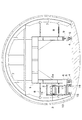
以下、本発明を具体化した実施形態を図面に基づいて説明する。図1,図2に示すように、この実施形態のトンネル工事設備には、作業台車としてのコンクリート二次覆工作業等を行うセントル1と、トンネルの切羽近くからセントル1を通過して坑口側へ連続的に延びるズリ出し用の延伸コンベア2と、延伸コンベア2をトンネル軸線方向のセントル1の設置区間(結果的に延伸コンベア2とセントル1とが並行する区間)で支持するコンベア支持装置3とが配置されている。また、図示はしないが、セントル1より切羽側には、防水シートの展張作業等を行うシート台車が配置され、シート台車の設置区間に、セントル1と同じ構造のコンベア支持装置が設置されている。
DESCRIPTION OF THE PREFERRED EMBODIMENTS Embodiments embodying the present invention will be described below with reference to the drawings. As shown in FIG. 1 and FIG. 2, the tunnel construction facility of this embodiment includes a center 1 for performing a concrete secondary lining work as a work carriage, and the tunnel side passing through the center 1 near the tunnel face. A
セントル1はトンネルの床レール4上に設置され、床レール4上を転動する車輪5と、車輪5を駆動する自走用モータ6と、型枠7を保持するターンパックル8と、型枠7を昇降するジャッキ9と、作業者用の足場(図示略)とを備えている。延伸コンベア2にはベルトコンベアが用いられ、そのフレーム2aはトンネルの片方の側壁面とセントル1との間をトンネル軸線方向へ延びるように配置されている。そして、延伸コンベア2は、セントル1より切羽側の区間で、保持部材10により一次覆工後のトンネル壁面に保持され、セントル1より坑口側の区間では、保持部材11により二次覆工後のトンネル壁面に保持されている。
The center 1 is installed on the
コンベア支持装置3は、セントル1より切羽側に位置する前支持具としての前脚13と、セントル1より坑口側に位置する後支持具としての後脚14と、前脚13及び後脚14の上端間に架設されたトラス構造の支持桁15とからなり、全体が延伸コンベア2と同じ幅でセントル1よりもトンネル軸線方向へ長く形成されている。前脚13及び後脚14の下端には、(本例では床レール4よりトンネル壁面側で)トンネルの床面に支持される走行装置としてのゴム製の車輪(ゴムタイヤ)16が設けられている。また、前脚13及び後脚14の両方には、車輪16を駆動する走行用モータ17,18が設置され、前側のモータ17で支持装置3を切羽側へ移動し、後側のモータ18で支持装置3を坑口側へ移動できるようになっている。
The conveyor support device 3 includes a
図3,図4に示すように、支持桁15は四角筒形の長尺トラス構造体であって、4本の主桁15aの間に多数本の上梁15b、底梁15c、左側梁15d、右側梁15e、筋交い15fを張り渡して構成されている。支持桁15の底部には、延伸コンベア2を支持する複数のローラ19が配設され、各ローラ19はブラケット20と底梁15cとの間に介在するスプリング21により支持桁15に対し昇降可能に支持されている。そして、ローラ19と対応する位置の左側梁15d及び右側梁15eに、延伸コンベア2のフレーム2aに外側から係合する板状のガイド22が支持桁15の長手方向へ一列に並ぶように突設されている。
As shown in FIGS. 3 and 4, the
上記のように構成されたコンベア支持装置3は、以下のような作用効果を発揮する。
(a)セントル1の設置区間において、延伸コンベア2は支持桁15により支持され、支持桁15が前脚13及び後脚14の車輪16を介してトンネル床面に支持される。また、支持桁15は撓みの少ないトラス構造体であるから、セントル1に支持桁15を支持する部材を設ける必要がなくなり、延伸コンベア2がセントル1から力学的に切り離される。従って、セントル1の移動に際し、このセントル1が床レール4の蛇行や不陸によって揺れた場合でも、セントル1の揺れが延伸コンベア2に伝わるおそれがなく、延伸コンベア2を常に安定した状態で稼働させることができる。
The conveyor support device 3 configured as described above exhibits the following operational effects.
(A) In the installation section of the centle 1, the stretching
(b)延伸コンベア2がセントル1から切り離されているので、型枠7の高さ調整に際し、ジャッキ9でセントル1を昇降した場合でも、延伸コンベア2の高さに変化が生じない。従って、延伸コンベア2とは無関係に、型枠7の高さを容易に調整することができる。
(B) Since the stretching
(c)延伸コンベア2がセントル1よりも長い支持桁15で支持されているため、セントル1をコンベア支持装置3と同時に移動してもよく、コンベア支持装置3の停止状態でセントル1を単独で移動してもよく、作業状況に応じて工程を柔軟に管理することができる。また、セントル1を単独で移動した場合は、延伸コンベア2のトンネル壁面に対する切り離し作業及び保持作業を省略でき、セントル1の移動に付帯するコンベア2の支持替え作業を簡略化することができる。
(C) Since the stretching
(d)前脚13及び後脚14の車輪16が床レール4よりトンネル壁面側でトンネル床面に支持されているので、コンベア支持装置3の幅が延伸コンベア2とほぼ等しくなる。従って、コンベア支持装置3の全体をセントル1とトンネル壁面との間にコンパクトに収めることができ、セントル1の前後に立ちはだかる門形架台をなくし、装置全体を小型化し、安価に製作することができる。
(D) Since the
(e)前脚13及び後脚14の両方に走行用モータ17,18が設置されているので、作業者は、コンベア支持装置3の前進時に、前脚13の近くでモータ17を操作でき、支持装置3の後退時には、後脚14の近くでモータ18を操作できて、長尺の支持装置3を前後へ安全に移動することができる。
(E) Since the traveling
(f)支持桁15の底部に複数のガイド22が一列に並設されているので、コンベア支持装置3を移動する際に、ガイド22により延伸コンベア2の蛇行を自動的に修正でき、延伸コンベア2が支持桁15の内側をスムーズに通過する。
(F) Since the plurality of
(g)延伸コンベア2を支持するローラ19がスプリング21により支持桁15に対し昇降可能に支持されているので、コンベア支持装置3を移動する際に、トンネル床面の不陸による支持桁15の振動をスプリング21で吸収して、延伸コンベア2を静止した状態に保持することができる。
(G) Since the
なお、本発明は前記実施形態に限定されるものではなく、例えば以下のように、発明の趣旨から逸脱しない範囲で適宜変更して具体化することもできる。
(1)延伸コンベア2をトンネルの左右両側の壁面に沿わせて配置した工事設備において、コンベア支持装置3をセントル1の左右両側に2台設置する。
(2)シート台車とセントルとを装備したトンネル工事設備において、コンベア支持装置の前支持具をシート台車より切羽側に配置し、後支持具をセントルより坑口側に配置し、前支持具及び後支持具の上端間に支持桁を架設し、前支持具及び後支持具の間に支持桁を受ける中間支持具を設ける。
(3)支持桁の周囲に防塵及び防護用のカバー部材を被せる。
(4)支持桁に上面が開いた溝形のトラス構造体を用いる。
In addition, this invention is not limited to the said embodiment, For example, it can also be suitably changed and embodied as follows, for example in the range which does not deviate from the meaning of invention.
(1) In the construction facility in which the stretching
(2) In tunnel construction equipment equipped with a seat carriage and a centle, the front support of the conveyor support device is located on the face side from the seat trolley, the rear support is located on the wellhead side from the centle, and the front support and rear A support beam is installed between the upper ends of the support devices, and an intermediate support device for receiving the support beam is provided between the front support device and the rear support device.
(3) Put a dust and protective cover around the support beam.
(4) A truss-shaped truss structure with an open upper surface is used for the support beam.
1 作業台車としてのセントル
2 延伸コンベア
2a フレーム
3 コンベア支持装置
4 床レール
13 前支持具としての前脚
14 後支持具としての後脚
15 支持桁
16 走行装置としての車輪
17 走行用モータ
18 走行用モータ
19 ローラ
21 スプリング
22 ガイド
DESCRIPTION OF SYMBOLS 1 Centle as a
Claims (6)
Priority Applications (1)
| Application Number | Priority Date | Filing Date | Title |
|---|---|---|---|
| JP2003358080A JP4072109B2 (en) | 2003-10-17 | 2003-10-17 | Conveyor support device for tunnel construction equipment |
Applications Claiming Priority (1)
| Application Number | Priority Date | Filing Date | Title |
|---|---|---|---|
| JP2003358080A JP4072109B2 (en) | 2003-10-17 | 2003-10-17 | Conveyor support device for tunnel construction equipment |
Publications (3)
| Publication Number | Publication Date |
|---|---|
| JP2005120746A JP2005120746A (en) | 2005-05-12 |
| JP2005120746A5 JP2005120746A5 (en) | 2006-09-07 |
| JP4072109B2 true JP4072109B2 (en) | 2008-04-09 |
Family
ID=34614776
Family Applications (1)
| Application Number | Title | Priority Date | Filing Date |
|---|---|---|---|
| JP2003358080A Expired - Lifetime JP4072109B2 (en) | 2003-10-17 | 2003-10-17 | Conveyor support device for tunnel construction equipment |
Country Status (1)
| Country | Link |
|---|---|
| JP (1) | JP4072109B2 (en) |
Families Citing this family (5)
| Publication number | Priority date | Publication date | Assignee | Title |
|---|---|---|---|---|
| JP6372052B2 (en) * | 2013-06-06 | 2018-08-15 | 株式会社大林組 | Tunnel construction method |
| JP6200703B2 (en) * | 2013-06-25 | 2017-09-20 | 株式会社大林組 | Belt conveyor frame for tunnel construction and tunnel construction method |
| CN103726499B (en) * | 2013-12-17 | 2016-07-06 | 中国水利水电第十三工程局有限公司 | A kind of roadbed side slope protection truss chassis and construction method |
| CN104712356B (en) * | 2015-02-04 | 2016-09-14 | 郑东风 | A kind of hydraulic pressure supports tunnel sectional shelf-unit and construction method from moving circulation |
| CN106968684B (en) * | 2017-05-27 | 2019-06-11 | 云南公投建设集团第一工程有限公司 | Constructing tunnel shrinkage type rack and the method constructed using it |
-
2003
- 2003-10-17 JP JP2003358080A patent/JP4072109B2/en not_active Expired - Lifetime
Also Published As
| Publication number | Publication date |
|---|---|
| JP2005120746A (en) | 2005-05-12 |
Similar Documents
| Publication | Publication Date | Title |
|---|---|---|
| JP4403579B2 (en) | Removal method of existing pier of overpass | |
| JP5485076B2 (en) | Tunnel construction equipment and construction method | |
| JP2016041861A (en) | Bridge inspection apparatus | |
| JP2017040103A (en) | Tunnel ceiling face grinding device | |
| JP2016166453A (en) | Floor slab construction device | |
| JP4072109B2 (en) | Conveyor support device for tunnel construction equipment | |
| JPH0841828A (en) | Bridge girder erection equipment | |
| JP6058333B2 (en) | Continuous belt conveyor height position change system | |
| JP2009024464A (en) | Delivery truck | |
| JP5793062B2 (en) | Tunnel construction apparatus and tunnel construction method | |
| JP7241612B2 (en) | Cutting equipment and cutting method | |
| JP4474445B2 (en) | Delivery method | |
| JP2019007137A (en) | Erection machine and moving method of erection machine | |
| JP2007290826A (en) | Method for carrying in/out component of passenger conveyor, method for modifying passenger conveyor using the method, and device for carrying in/out component of passenger conveyor used for the method | |
| JPH09256323A (en) | Bridge girder installing apparatus | |
| JP2000025933A (en) | Support mechanism of continuous belt conveyor | |
| JP4173758B2 (en) | Support device for continuous belt conveyor for tunnel construction | |
| JP2005120746A5 (en) | ||
| KR970011231A (en) | Method and device of moving scaffold for bridge construction | |
| KR100591944B1 (en) | Transport unit of work unit | |
| JP7249216B2 (en) | CONCRETE WALL REMOVAL DEVICE AND CONCRETE WALL REMOVAL METHOD | |
| JP4392609B2 (en) | Tunnel material transport equipment | |
| JP2019189174A (en) | Passenger boarding bridge | |
| KR101222487B1 (en) | Apparatus for installing a platform screen door module | |
| JPS6220366Y2 (en) |
Legal Events
| Date | Code | Title | Description |
|---|---|---|---|
| A521 | Request for written amendment filed |
Free format text: JAPANESE INTERMEDIATE CODE: A523 Effective date: 20060725 |
|
| A621 | Written request for application examination |
Free format text: JAPANESE INTERMEDIATE CODE: A621 Effective date: 20060725 |
|
| A977 | Report on retrieval |
Free format text: JAPANESE INTERMEDIATE CODE: A971007 Effective date: 20071220 |
|
| TRDD | Decision of grant or rejection written | ||
| A01 | Written decision to grant a patent or to grant a registration (utility model) |
Free format text: JAPANESE INTERMEDIATE CODE: A01 Effective date: 20080108 |
|
| A61 | First payment of annual fees (during grant procedure) |
Free format text: JAPANESE INTERMEDIATE CODE: A61 Effective date: 20080118 |
|
| R150 | Certificate of patent or registration of utility model |
Free format text: JAPANESE INTERMEDIATE CODE: R150 Ref document number: 4072109 Country of ref document: JP Free format text: JAPANESE INTERMEDIATE CODE: R150 |
|
| FPAY | Renewal fee payment (event date is renewal date of database) |
Free format text: PAYMENT UNTIL: 20110125 Year of fee payment: 3 |
|
| FPAY | Renewal fee payment (event date is renewal date of database) |
Free format text: PAYMENT UNTIL: 20140125 Year of fee payment: 6 |
|
| R250 | Receipt of annual fees |
Free format text: JAPANESE INTERMEDIATE CODE: R250 |
|
| R250 | Receipt of annual fees |
Free format text: JAPANESE INTERMEDIATE CODE: R250 |
|
| S531 | Written request for registration of change of domicile |
Free format text: JAPANESE INTERMEDIATE CODE: R313531 |
|
| R350 | Written notification of registration of transfer |
Free format text: JAPANESE INTERMEDIATE CODE: R350 |
|
| S111 | Request for change of ownership or part of ownership |
Free format text: JAPANESE INTERMEDIATE CODE: R313117 |
|
| R350 | Written notification of registration of transfer |
Free format text: JAPANESE INTERMEDIATE CODE: R350 |
|
| R250 | Receipt of annual fees |
Free format text: JAPANESE INTERMEDIATE CODE: R250 |
|
| R250 | Receipt of annual fees |
Free format text: JAPANESE INTERMEDIATE CODE: R250 |
|
| R250 | Receipt of annual fees |
Free format text: JAPANESE INTERMEDIATE CODE: R250 |
|
| R250 | Receipt of annual fees |
Free format text: JAPANESE INTERMEDIATE CODE: R250 |
|
| R250 | Receipt of annual fees |
Free format text: JAPANESE INTERMEDIATE CODE: R250 |
|
| R250 | Receipt of annual fees |
Free format text: JAPANESE INTERMEDIATE CODE: R250 |
|
| R250 | Receipt of annual fees |
Free format text: JAPANESE INTERMEDIATE CODE: R250 |
|
| EXPY | Cancellation because of completion of term |