JP4063655B2 - Conductive electroless plating powder and manufacturing method thereof - Google Patents
Conductive electroless plating powder and manufacturing method thereof Download PDFInfo
- Publication number
- JP4063655B2 JP4063655B2 JP2002366942A JP2002366942A JP4063655B2 JP 4063655 B2 JP4063655 B2 JP 4063655B2 JP 2002366942 A JP2002366942 A JP 2002366942A JP 2002366942 A JP2002366942 A JP 2002366942A JP 4063655 B2 JP4063655 B2 JP 4063655B2
- Authority
- JP
- Japan
- Prior art keywords
- layer
- complexing agent
- powder
- aqueous suspension
- containing liquid
- Prior art date
- Legal status (The legal status is an assumption and is not a legal conclusion. Google has not performed a legal analysis and makes no representation as to the accuracy of the status listed.)
- Expired - Lifetime
Links
Images


Classifications
-
- C—CHEMISTRY; METALLURGY
- C23—COATING METALLIC MATERIAL; COATING MATERIAL WITH METALLIC MATERIAL; CHEMICAL SURFACE TREATMENT; DIFFUSION TREATMENT OF METALLIC MATERIAL; COATING BY VACUUM EVAPORATION, BY SPUTTERING, BY ION IMPLANTATION OR BY CHEMICAL VAPOUR DEPOSITION, IN GENERAL; INHIBITING CORROSION OF METALLIC MATERIAL OR INCRUSTATION IN GENERAL
- C23C—COATING METALLIC MATERIAL; COATING MATERIAL WITH METALLIC MATERIAL; SURFACE TREATMENT OF METALLIC MATERIAL BY DIFFUSION INTO THE SURFACE, BY CHEMICAL CONVERSION OR SUBSTITUTION; COATING BY VACUUM EVAPORATION, BY SPUTTERING, BY ION IMPLANTATION OR BY CHEMICAL VAPOUR DEPOSITION, IN GENERAL
- C23C18/00—Chemical coating by decomposition of either liquid compounds or solutions of the coating forming compounds, without leaving reaction products of surface material in the coating; Contact plating
- C23C18/16—Chemical coating by decomposition of either liquid compounds or solutions of the coating forming compounds, without leaving reaction products of surface material in the coating; Contact plating by reduction or substitution, e.g. electroless plating
- C23C18/31—Coating with metals
- C23C18/32—Coating with nickel, cobalt or mixtures thereof with phosphorus or boron
- C23C18/34—Coating with nickel, cobalt or mixtures thereof with phosphorus or boron using reducing agents
-
- C—CHEMISTRY; METALLURGY
- C23—COATING METALLIC MATERIAL; COATING MATERIAL WITH METALLIC MATERIAL; CHEMICAL SURFACE TREATMENT; DIFFUSION TREATMENT OF METALLIC MATERIAL; COATING BY VACUUM EVAPORATION, BY SPUTTERING, BY ION IMPLANTATION OR BY CHEMICAL VAPOUR DEPOSITION, IN GENERAL; INHIBITING CORROSION OF METALLIC MATERIAL OR INCRUSTATION IN GENERAL
- C23C—COATING METALLIC MATERIAL; COATING MATERIAL WITH METALLIC MATERIAL; SURFACE TREATMENT OF METALLIC MATERIAL BY DIFFUSION INTO THE SURFACE, BY CHEMICAL CONVERSION OR SUBSTITUTION; COATING BY VACUUM EVAPORATION, BY SPUTTERING, BY ION IMPLANTATION OR BY CHEMICAL VAPOUR DEPOSITION, IN GENERAL
- C23C18/00—Chemical coating by decomposition of either liquid compounds or solutions of the coating forming compounds, without leaving reaction products of surface material in the coating; Contact plating
- C23C18/16—Chemical coating by decomposition of either liquid compounds or solutions of the coating forming compounds, without leaving reaction products of surface material in the coating; Contact plating by reduction or substitution, e.g. electroless plating
- C23C18/1601—Process or apparatus
- C23C18/1633—Process of electroless plating
- C23C18/1635—Composition of the substrate
-
- C—CHEMISTRY; METALLURGY
- C23—COATING METALLIC MATERIAL; COATING MATERIAL WITH METALLIC MATERIAL; CHEMICAL SURFACE TREATMENT; DIFFUSION TREATMENT OF METALLIC MATERIAL; COATING BY VACUUM EVAPORATION, BY SPUTTERING, BY ION IMPLANTATION OR BY CHEMICAL VAPOUR DEPOSITION, IN GENERAL; INHIBITING CORROSION OF METALLIC MATERIAL OR INCRUSTATION IN GENERAL
- C23C—COATING METALLIC MATERIAL; COATING MATERIAL WITH METALLIC MATERIAL; SURFACE TREATMENT OF METALLIC MATERIAL BY DIFFUSION INTO THE SURFACE, BY CHEMICAL CONVERSION OR SUBSTITUTION; COATING BY VACUUM EVAPORATION, BY SPUTTERING, BY ION IMPLANTATION OR BY CHEMICAL VAPOUR DEPOSITION, IN GENERAL
- C23C18/00—Chemical coating by decomposition of either liquid compounds or solutions of the coating forming compounds, without leaving reaction products of surface material in the coating; Contact plating
- C23C18/16—Chemical coating by decomposition of either liquid compounds or solutions of the coating forming compounds, without leaving reaction products of surface material in the coating; Contact plating by reduction or substitution, e.g. electroless plating
- C23C18/1601—Process or apparatus
- C23C18/1633—Process of electroless plating
- C23C18/1646—Characteristics of the product obtained
- C23C18/165—Multilayered product
- C23C18/1651—Two or more layers only obtained by electroless plating
-
- C—CHEMISTRY; METALLURGY
- C23—COATING METALLIC MATERIAL; COATING MATERIAL WITH METALLIC MATERIAL; CHEMICAL SURFACE TREATMENT; DIFFUSION TREATMENT OF METALLIC MATERIAL; COATING BY VACUUM EVAPORATION, BY SPUTTERING, BY ION IMPLANTATION OR BY CHEMICAL VAPOUR DEPOSITION, IN GENERAL; INHIBITING CORROSION OF METALLIC MATERIAL OR INCRUSTATION IN GENERAL
- C23C—COATING METALLIC MATERIAL; COATING MATERIAL WITH METALLIC MATERIAL; SURFACE TREATMENT OF METALLIC MATERIAL BY DIFFUSION INTO THE SURFACE, BY CHEMICAL CONVERSION OR SUBSTITUTION; COATING BY VACUUM EVAPORATION, BY SPUTTERING, BY ION IMPLANTATION OR BY CHEMICAL VAPOUR DEPOSITION, IN GENERAL
- C23C18/00—Chemical coating by decomposition of either liquid compounds or solutions of the coating forming compounds, without leaving reaction products of surface material in the coating; Contact plating
- C23C18/16—Chemical coating by decomposition of either liquid compounds or solutions of the coating forming compounds, without leaving reaction products of surface material in the coating; Contact plating by reduction or substitution, e.g. electroless plating
- C23C18/18—Pretreatment of the material to be coated
- C23C18/1803—Pretreatment of the material to be coated of metallic material surfaces or of a non-specific material surfaces
- C23C18/1824—Pretreatment of the material to be coated of metallic material surfaces or of a non-specific material surfaces by chemical pretreatment
- C23C18/1827—Pretreatment of the material to be coated of metallic material surfaces or of a non-specific material surfaces by chemical pretreatment only one step pretreatment
- C23C18/1831—Use of metal, e.g. activation, sensitisation with noble metals
-
- C—CHEMISTRY; METALLURGY
- C23—COATING METALLIC MATERIAL; COATING MATERIAL WITH METALLIC MATERIAL; CHEMICAL SURFACE TREATMENT; DIFFUSION TREATMENT OF METALLIC MATERIAL; COATING BY VACUUM EVAPORATION, BY SPUTTERING, BY ION IMPLANTATION OR BY CHEMICAL VAPOUR DEPOSITION, IN GENERAL; INHIBITING CORROSION OF METALLIC MATERIAL OR INCRUSTATION IN GENERAL
- C23C—COATING METALLIC MATERIAL; COATING MATERIAL WITH METALLIC MATERIAL; SURFACE TREATMENT OF METALLIC MATERIAL BY DIFFUSION INTO THE SURFACE, BY CHEMICAL CONVERSION OR SUBSTITUTION; COATING BY VACUUM EVAPORATION, BY SPUTTERING, BY ION IMPLANTATION OR BY CHEMICAL VAPOUR DEPOSITION, IN GENERAL
- C23C18/00—Chemical coating by decomposition of either liquid compounds or solutions of the coating forming compounds, without leaving reaction products of surface material in the coating; Contact plating
- C23C18/16—Chemical coating by decomposition of either liquid compounds or solutions of the coating forming compounds, without leaving reaction products of surface material in the coating; Contact plating by reduction or substitution, e.g. electroless plating
- C23C18/18—Pretreatment of the material to be coated
- C23C18/1851—Pretreatment of the material to be coated of surfaces of non-metallic or semiconducting in organic material
- C23C18/1872—Pretreatment of the material to be coated of surfaces of non-metallic or semiconducting in organic material by chemical pretreatment
- C23C18/1875—Pretreatment of the material to be coated of surfaces of non-metallic or semiconducting in organic material by chemical pretreatment only one step pretreatment
- C23C18/1879—Use of metal, e.g. activation, sensitisation with noble metals
-
- C—CHEMISTRY; METALLURGY
- C23—COATING METALLIC MATERIAL; COATING MATERIAL WITH METALLIC MATERIAL; CHEMICAL SURFACE TREATMENT; DIFFUSION TREATMENT OF METALLIC MATERIAL; COATING BY VACUUM EVAPORATION, BY SPUTTERING, BY ION IMPLANTATION OR BY CHEMICAL VAPOUR DEPOSITION, IN GENERAL; INHIBITING CORROSION OF METALLIC MATERIAL OR INCRUSTATION IN GENERAL
- C23C—COATING METALLIC MATERIAL; COATING MATERIAL WITH METALLIC MATERIAL; SURFACE TREATMENT OF METALLIC MATERIAL BY DIFFUSION INTO THE SURFACE, BY CHEMICAL CONVERSION OR SUBSTITUTION; COATING BY VACUUM EVAPORATION, BY SPUTTERING, BY ION IMPLANTATION OR BY CHEMICAL VAPOUR DEPOSITION, IN GENERAL
- C23C18/00—Chemical coating by decomposition of either liquid compounds or solutions of the coating forming compounds, without leaving reaction products of surface material in the coating; Contact plating
- C23C18/16—Chemical coating by decomposition of either liquid compounds or solutions of the coating forming compounds, without leaving reaction products of surface material in the coating; Contact plating by reduction or substitution, e.g. electroless plating
- C23C18/18—Pretreatment of the material to be coated
- C23C18/20—Pretreatment of the material to be coated of organic surfaces, e.g. resins
- C23C18/28—Sensitising or activating
- C23C18/30—Activating or accelerating or sensitising with palladium or other noble metal
-
- C—CHEMISTRY; METALLURGY
- C23—COATING METALLIC MATERIAL; COATING MATERIAL WITH METALLIC MATERIAL; CHEMICAL SURFACE TREATMENT; DIFFUSION TREATMENT OF METALLIC MATERIAL; COATING BY VACUUM EVAPORATION, BY SPUTTERING, BY ION IMPLANTATION OR BY CHEMICAL VAPOUR DEPOSITION, IN GENERAL; INHIBITING CORROSION OF METALLIC MATERIAL OR INCRUSTATION IN GENERAL
- C23C—COATING METALLIC MATERIAL; COATING MATERIAL WITH METALLIC MATERIAL; SURFACE TREATMENT OF METALLIC MATERIAL BY DIFFUSION INTO THE SURFACE, BY CHEMICAL CONVERSION OR SUBSTITUTION; COATING BY VACUUM EVAPORATION, BY SPUTTERING, BY ION IMPLANTATION OR BY CHEMICAL VAPOUR DEPOSITION, IN GENERAL
- C23C18/00—Chemical coating by decomposition of either liquid compounds or solutions of the coating forming compounds, without leaving reaction products of surface material in the coating; Contact plating
- C23C18/16—Chemical coating by decomposition of either liquid compounds or solutions of the coating forming compounds, without leaving reaction products of surface material in the coating; Contact plating by reduction or substitution, e.g. electroless plating
- C23C18/31—Coating with metals
- C23C18/32—Coating with nickel, cobalt or mixtures thereof with phosphorus or boron
- C23C18/34—Coating with nickel, cobalt or mixtures thereof with phosphorus or boron using reducing agents
- C23C18/36—Coating with nickel, cobalt or mixtures thereof with phosphorus or boron using reducing agents using hypophosphites
-
- H—ELECTRICITY
- H01—ELECTRIC ELEMENTS
- H01B—CABLES; CONDUCTORS; INSULATORS; SELECTION OF MATERIALS FOR THEIR CONDUCTIVE, INSULATING OR DIELECTRIC PROPERTIES
- H01B1/00—Conductors or conductive bodies characterised by the conductive materials; Selection of materials as conductors
- H01B1/20—Conductive material dispersed in non-conductive organic material
- H01B1/22—Conductive material dispersed in non-conductive organic material the conductive material comprising metals or alloys
-
- C—CHEMISTRY; METALLURGY
- C23—COATING METALLIC MATERIAL; COATING MATERIAL WITH METALLIC MATERIAL; CHEMICAL SURFACE TREATMENT; DIFFUSION TREATMENT OF METALLIC MATERIAL; COATING BY VACUUM EVAPORATION, BY SPUTTERING, BY ION IMPLANTATION OR BY CHEMICAL VAPOUR DEPOSITION, IN GENERAL; INHIBITING CORROSION OF METALLIC MATERIAL OR INCRUSTATION IN GENERAL
- C23C—COATING METALLIC MATERIAL; COATING MATERIAL WITH METALLIC MATERIAL; SURFACE TREATMENT OF METALLIC MATERIAL BY DIFFUSION INTO THE SURFACE, BY CHEMICAL CONVERSION OR SUBSTITUTION; COATING BY VACUUM EVAPORATION, BY SPUTTERING, BY ION IMPLANTATION OR BY CHEMICAL VAPOUR DEPOSITION, IN GENERAL
- C23C18/00—Chemical coating by decomposition of either liquid compounds or solutions of the coating forming compounds, without leaving reaction products of surface material in the coating; Contact plating
- C23C18/54—Contact plating, i.e. electroless electrochemical plating
Description
【0001】
【発明の属する技術分野】
本発明は、導電性無電解めっき粉体及びその製造方法に関するものであり、更に詳しくは芯材粉体との密着性や耐熱性が向上したニッケル皮膜を有する導電性無電解めっき粉体及びその製造方法に関する。
【0002】
【従来の技術及び発明が解決しようとする課題】
本出願人は先に、合成樹脂の芯材粉体に無電解めっきを行う方法として、合成樹脂の芯材粉体に貴金属捕捉性表面処理剤を用いて貴金属イオンを坦持させた後に、めっき液中に投入して無電解めっき処理を行う方法を提案した(特許文献1参照)。この方法はいわゆる建浴方式とよばれるものであり、めっき液には金属塩、還元剤、錯化剤、緩衝剤、安定剤などが含まれる。この方法によればめっき皮膜と芯材粉体との密着性が向上するという利点がある。密着性を更に向上させるべく、本出願人は前記無電解めっき方法を更に改良した方法も提案している(特許文献2参照)。
【0003】
しかし、無電解めっき粉末に要求される各種性能は日増しに厳しくなり、めっき皮膜と芯材粉体との密着性についての要求も厳しくなっており、特に高温での安定性(耐熱性)が要求されている。
【0004】
【特許文献1】
特開昭61−64882号公報
【特許文献2】
特開平1−242782号公報
【0005】
従って、本発明は、めっき皮膜と芯材粉体との密着性や耐熱性が向上した導電性無電解めっき粉体及びその製造方法を提供することを目的とする。
【0006】
【課題を解決するための手段】
本発明者らは鋭意検討した結果、前記特許文献1に記載されてるめっき皮膜の構造、即ち微細な金属粒子が濃密で実質的な連続皮膜を呈している構造とは異なり、同種の金属からなり且つ結晶の配向状態が互いに異なる2層構造の皮膜を形成することによって前記目的が達成されることを知見した。
【0007】
本発明は、芯材粒子の表面に無電解めっき法によってニッケル皮膜を形成した導電性無電解めっき粉体において、前記ニッケル皮膜が、前記芯材粒子の表面に形成された第1の層と該第1の層に隣接して形成された第2の層とを含み、該第1の層及び該第2の層それぞれにおける粒界の配向方向が互いに異なっていることを特徴とする導電性無電解めっき粉体を提供することにより前記目的を達成したものである。
【0008】
また本発明は、前記導電性無電解めっき粉体の一実施形態の好ましい製造方法として、
貴金属イオンの捕捉能を有するか又は表面処理によって貴金属イオンの捕捉能を付与した芯材粉体に貴金属イオンを捕捉させた後、これを還元して前記貴金属を該芯材粉体の表面に担持させ、次いで該芯材粉体を、有機カルボン酸又はその塩からなる錯化剤を含有する水性媒体に分散させて第1の水性懸濁体を調製し、これに前記錯化剤と同種の錯化剤を含有する第1のニッケルイオン含有液及び第1の還元剤含有液の2液を個別かつ同時に添加して無電解めっき反応を行わせて第1の層を形成し、次いで該第1の層が形成された芯材粉体を、アミン化合物からなる錯化剤を含有する水性媒体に分散させて第2の水性懸濁体を調製し、該第2の水性懸濁体に、これに含まれる錯化剤と同種の錯化剤を含有する第2のニッケルイオン含有液及び第2の還元剤含有液の2液を個別かつ同時に添加して無電解めっき反応を行わせて前記第1の層上に第2の層を形成することを特徴とする導電性無電解めっき粉体の製造方法を提供することにより前記目的を達成したものである。
【0009】
更に本発明は、前記導電性無電解めっき粉体の別の実施形態の好ましい製造方法として、
貴金属イオンの捕捉能を有するか又は表面処理によって貴金属イオンの捕捉能を付与した芯材粉体に貴金属イオンを捕捉させた後、これを還元して前記貴金属を該芯材粉体の表面に担持させ、次いで該芯材粉体を、アミン化合物からなる錯化剤を含有する水性媒体に分散させて第1の水性懸濁体を調製し、これに前記錯化剤と同種の錯化剤を含有する第1のニッケルイオン含有液及び第1の還元剤含有液の2液を個別かつ同時に添加して無電解めっき反応を行わせて第1の層を形成し、次いで該第1の層が形成された芯材粉体を、有機カルボン酸又はその塩からなる錯化剤を含有する水性媒体に分散させて第2の水性懸濁体を調製し、該第2の水性懸濁体に、これに含まれる錯化剤と同種の錯化剤を含有する第2のニッケルイオン含有液及び第2の還元剤含有液の2液を個別かつ同時に添加して無電解めっき反応を行わせて前記第1の層上に第2の層を形成することを特徴とする導電性無電解めっき粉体の製造方法を提供することにより前記目的を達成したものである。
【0010】
【発明の実施の形態】
以下本発明を、その好ましい実施形態に基づき図面を参照しながら説明する。本発明の第1の実施形態の導電性無電解めっき粉体(以下、単にめっき粉体ともいう)は、芯材粉体の表面に無電解めっき法によってニッケル皮膜が形成されてなるものである。ニッケル皮膜は、芯材粒子の表面に形成された第1の層と該第1の層に隣接して形成された第2の層との少なくとも2層を含んでいる。
【0011】
芯材粉体の表面に形成された第1の層は、該層の厚さ方向断面に結晶粒界が認められないものである。結晶粒界が認められないとは、結晶粒界が存在していない場合及び結晶粒界が存在していてもそれが微小すぎて観察されない場合の双方を含む。第1の層の厚さ方向断面に結晶粒界が認められるか否かは、走査型電子顕微鏡(以下、SEMともいう)観察によって視覚的にとらえることができる。具体的には、SEMによって100000倍迄の拡大倍率で第1の層の厚さ方向断面を観察したときに、結晶粒界が観察されない場合には、結晶粒界が認められないと言うことができる。
【0012】
第1の層上に形成された第2の層は、該層中の粒界が、該層の主として厚さ方向に配向しているものである。つまり、第2の層中の結晶は、主として該層の厚さ方向に延びる柱状構造となっている。第2の層の粒界が、該層の厚さ方向に配向しているか否かは、第1の層の場合と同様に、SEM観察によって視覚的にとらえることができる。具体的には、SEMによって100000倍迄の拡大倍率で第2の層の厚さ方向断面を観察したときに、該層の厚さ方向に延びる柱状構造が観察される場合には、結晶粒界が厚さ方向に主として配向していると言うことができる。
【0013】
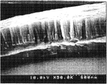
図1には、本発明のめっき粉体の第1の実施形態を示すSEM写真が示されている。拡大倍率は50000倍である。図1から明らかなように、めっき粉体におけるニッケル皮膜は、芯材粒子の表面に形成された第1の層と第1の層に隣接して形成された第2の層とから構成されている。第1の層には、その厚さ方向断面に結晶粒界が観察されない。また第2の層は、その厚さ方向に延びる多数の柱状構造から構成されている。図1では、第2の層における各柱状構造は、その高さの方がその幅よりも大きくなっているが、第2の層の形成方法によっては、柱状構造の高さと幅がほぼ同じ場合や、高さよりも幅の方が大きい場合もある。更に、截頭錐体形状やその倒立形状であり得る場合もある。一方、従来品である図3に示す無電解ニッケルめっき粉体のSEM写真(拡大倍率は図1と同じ)においては、ニッケル皮膜は明確な2層構造を有しておらず、その厚さ方向断面に、瘤形状の結晶粒界が観察されるのみである。
【0014】
図1から明らかなように、第1の実施形態のめっき粉体におけるニッケル皮膜は明確な2層構造を有しており、緻密かつ均質で連続膜となっている。一方、従来品である図3に示すめっき粉体におけるニッケル皮膜は結晶粒子が粗く且つ不均質となっている。後述する実施例から明らかなように、図1に示すような2層構造を有するニッケル皮膜(つまり、第1の層に結晶粒界が認められず、第2の層が厚さ方向に柱状構造を有するニッケル皮膜)は、芯材粉体の表面との密着性が極めて高いことが本発明者らの検討によって判明した。更に、耐熱性が高く、高温条件下でもめっき粉体の導電性が低下しづらいことが判明した。この理由は明らかでないが、芯材粉体の表面に存在する層である第1の層中に結晶粒子が存在しないか、或いは存在していたとしても極めて微小であるので、第1の層が緻密で均質なものとなり、その結果として芯材粉体の表面との密着性が高くなると推測される。
【0015】
めっき粉体におけるニッケル皮膜の断面をSEM観察する手順の一例は次の通りである。めっき粉体50重量部、エピコート815(ジャパンエポキシレジン株式会社製)100重量部、エピキュア(ジャパンエポキシレジン株式会社製)5重量部を混練し、110℃の乾燥機で10分硬化させて、10mm×l0mm×2mmの試料を成型する。得られた試料を折り曲げ破断させて、めっき皮膜の破断面が現れている部位をSEM観察する。
【0016】
本発明者らがX線回折測定を行った結果、ニッケル皮膜における第1及び第2の層は、それぞれ全くの非晶質というわけではなく一部結晶質の部分もあり、結晶質と非晶質とが混在している状態が一般的であることが判明した。尤も、各層における結晶形態は本発明において臨界的なものではなく、第1の層に結晶粒界が認められず、第2の層が厚さ方向に柱状構造を有すれば、各層が結晶質であると非晶質であるとを問わず所望の密着性及び耐熱性が発現する。
【0017】
ニッケル皮膜の厚さはその密着性に少なからず影響し、皮膜が厚すぎると芯材粉体からの落剥が起こって導電性が低下しやすい傾向にある。逆に、皮膜が薄すぎても所望の導電性が得られなくなる。これらの観点から、第1の層の厚さは0.0025〜5μm、特に0.005〜1μm程度であることが好ましい。第2の層の厚さもこれと同様の範囲であることが好ましい。更に第1及び第2の層を含むニッケル皮膜全体の厚さは0.005〜10μm、特に0.01〜2μm程度であることが好ましい。
【0018】
尚、ニッケル皮膜を無電解めっきによって形成する際に用いられる還元剤の種類によっては、ニッケル皮膜がニッケルと他の元素との合金となっている場合がある。例えば還元剤として次亜リン酸ナトリウムを用いる場合には、得られるニッケル皮膜はニッケル−リン合金となっている。しかし、本発明においては、このようなニッケル合金の皮膜も広義のニッケル皮膜と呼ぶ。
【0019】
本発明のめっき粉体は、芯材粉体の表面に前述のニッケル皮膜が形成されてなるものであるが、該めっき粉体の導電性を一層向上させる観点から、最表面に薄層の金めっき層が形成されていてもよい。金めっき層の厚さは一般に0.001〜0.5μm程度である。金めっき層の厚さは、金イオンの添加量や化学分析から算出することができる。
【0020】
ニッケル皮膜が形成される芯材粉体の種類に特に制限はなく、有機物粉体及び無機物粉体の何れもが用いられる。後述する無電解めっき法を考慮すると、芯材粉体は水に分散可能なものであることが好ましい。従って芯材粉体は、好ましくは水に実質的に不溶性のものであり、更に好ましくは酸やアルカリに対しても溶解または変質しないものである。水に分散可能とは、攪拌等の通常の分散手段によって、ニッケル皮膜が芯材粉体の表面に形成し得る程度に、水中に実質的に分散した懸濁体を形成し得ることをいう。
【0021】
芯材粉体の形状に特に制限はない。一般に芯材粉体は粉粒状であり得るが、それ以外の形状、例えば繊維状、中空状、板状、針状であってもよく、或いは不定形であってもよい。芯材粉体の大きさは、本発明のめっき粉体の具体的用途に応じて適切な大きさが選択される。例えば本発明のめっき粉体を電子回路接続用の導電材料として用いる場合には、芯材粉体は平均粒径0.5〜1000μm程度の球状粒子であることが好ましい。
【0022】
芯材粉体の具体例としては、無機物として、金属(合金も含む)、ガラス、セラミックス、シリカ、カーボン、金属または非金属の酸化物(含水物も含む)、アルミノ珪酸塩を含む金属珪酸塩、金属炭化物、金属窒化物、金属炭酸塩、金属硫酸塩、金属リン酸塩、金属硫化物、金属酸塩、金属ハロゲン化物及び炭素などが挙げられる。有機物としては、天然繊維、天然樹脂、ポリエチレン、ポリプロピレン、ポリ塩化ビニル、ポリスチレン、ポリブテン、ポリアミド、ポリアクリル酸エステル、ポリアクリロニトリル、ポリアセタール、アイオノマー、ポリエステルなどの熱可塑性樹脂、アルキッド樹脂、フェノール樹脂、尿素樹脂、メラミン樹脂、ベンゾグアナミン樹脂、メラミン樹脂、キシレン樹脂、シリコーン樹脂、エポキシ樹脂またはジアリルフタレート樹脂などが挙げられる。これらは単独でも使用でき又は2種以上の混合物として使用してもよい。
【0023】
芯材粉体は、その表面が貴金属イオンの捕捉能を有するか、又は貴金属イオンの捕捉能を有するように表面改質されることが好ましい。貴金属イオンは、パラジウムや銀のイオンであることが好ましい。貴金属イオンの捕捉能を有するとは、貴金属イオンをキレート又は塩として捕捉し得ることをいう。例えば芯材粉体の表面に、アミノ基、イミノ基、アミド基、イミド基、シアノ基、水酸基、ニトリル基、カルボキシル基などが存在する場合には、該芯材粉体の表面は貴金属イオンの捕捉能を有する。貴金属イオンの捕捉能を有するように表面改質する場合には、例えば特開昭61−64882号公報記載の方法を用いることができる。
【0024】
次に、本発明のめっき粉体の第2の実施形態について図2を参照しながら説明する。これらの実施形態については、第1の実施形態と異なる点についてのみ説明し、特に説明しない点については、第1の実施形態に関して詳述した説明が適宜適用される。
【0025】
図2には、本発明のめっき粉体の第2の実施形態を示すSEM写真が示されている。拡大倍率は図1と同様に50000倍である。図2から明らかなように、本実施形態におけるめっき粉体におけるニッケル皮膜は、第1の実施形態と同様に芯材粒子の表面に形成された第1の層と第1の層に隣接して形成された第2の層とから構成されている。但し本実施形態が第1の実施形態と異なる点は、第1の層が、その厚さ方向に延びる多数の柱状構造から構成されており、また第2の層には、その厚さ方向断面に結晶粒界が観察されない点である。つまり、本実施形態のめっき粉体におけるニッケル皮膜の2層構造は、第1実施形態のそれを上下逆転させた構造となっている。
【0026】
図2から明らかなように、本実施形態のニッケル皮膜は第1の実施形態のそれと同様に明確な2層構造を有しており、緻密かつ均質で連続膜となっている。後述する実施例から明らかなように、図2に示すような2層構造を有するニッケル皮膜(つまり、第1の層が厚さ方向に柱状構造を有し、第2の層に結晶粒界が認められないニッケル皮膜)は、耐熱性が高く、高温条件下でもめっき粉体の導電性が低下しづらいことが判明した。
【0027】
本実施形態における第1の層の厚さは、第1の実施形態における第2の層の厚さと同様とすることができる。また、本実施形態における第2の層の厚さは、第1の実施形態における第1の層の厚さと同様とすることができる。更に第1及び第2の層を含むニッケル皮膜全体の厚さも第1の実施形態と同様とすることができる。これらの理由は第1の実施形態の場合と同様である。
【0028】
次に、本発明のめっき粉体の好ましい製造方法について第1及び第2の実施形態のめっき粉体の製造を例にとり説明する。まず、第1の実施形態のめっき粉体の製造について説明する。第1の実施形態のめっき粉体の製造方法は、(A)第1の層の形成工程と、(B)第2の層の形成工程とに大別される。(A)の第1の層の形成工程には、(A1)触媒化処理工程と、(A2)初期薄膜形成工程と、(A3)無電解めっき工程とが含まれる。同様に(B)の第2の層の形成工程にも、(B1)触媒化処理工程と、(B2)初期薄膜形成工程と、(B3)無電解めっき工程とが含まれる。
【0029】
(A1)の触媒化処理工程においては、貴金属イオンの捕捉能を有するか又は表面処理によって貴金属イオンの捕捉能を付与した芯材粉体に貴金属イオンを捕捉させた後、これを還元して前記貴金属を前記芯材粉体の表面に担持させる。(A2)の初期薄膜形成工程においては、貴金属が坦持された芯材粉体を、ニッケルイオン、還元剤及び有機カルボン酸又はその塩からなる錯化剤を含む初期薄膜形成液に分散混合させ、ニッケルイオンを還元させて該芯材粉体の表面にニッケルの初期薄膜を形成する。(A3)の無電解めっき工程においては、ニッケルの初期薄膜が形成された芯材粉体及び前記錯化剤を含む水性懸濁体に、該錯化剤と同種の有機カルボン酸からなる錯化剤を含有するニッケルイオン含有液及び還元剤含有液の2液を個別かつ同時に添加して無電解めっき反応を行わせる。以下、それぞれの工程について詳述する。
【0030】
(A1)触媒化処理工程
芯材粉体自体が貴金属イオンの捕捉能を有する場合は、直接触媒化処理を行う。そうでない場合は表面改質処理を行う。表面改質処理は、表面処理剤を溶解した水又は有機溶媒に芯材粉体を加えて充分に攪拌して分散させた後、該粉体を分離し乾燥させる。表面処理剤の量は、芯材粉体の種類に応じ、粉体の比表面積1m2/g当り0.3〜100mgの範囲で調整することで、均一な改質効果が得られる。
【0031】
次に、芯材粉体を塩化パラジウムや硝酸銀のような貴金属塩の希薄な酸性水溶液に分散させる。これによって貴金属イオンを粉体表面に捕捉させる。貴金属塩濃度は粉体の表面積1m2当り1×10⁻⁷〜1×10⁻²モルの範囲で充分である。貴金属イオンが捕捉された芯材粉体は系から分離され水洗される。引き続き、芯材粉体を水に懸濁させ、これに還元剤を加えて貴金属イオンの還元処理を行う。これによって芯材粉体の表面に貴金属を坦持させる。還元剤としては、例えば次亜りん酸ナトリウム、水酸化ほう素ナトリウム、水素化ほう素カリウム、ジメチルアミンボラン、ヒドラジン、ホルマリン等が用いられる。
【0032】
貴金属イオンを芯材粉体の表面に捕捉させる前に、錫イオンを粉体表面に吸着させる感受性化処理を施してもよい。錫イオンを粉体表面に吸着させるには、例えば表面改質処理された芯材粉体を塩化第一錫の水溶液に投入し所定時間撹拌すればよい。
【0033】
(A2)初期薄膜形成工程
初期薄膜形成工程は、芯材粉体へのニッケルの均一析出及び芯材粉体の表面を平滑化する目的で行われる。初期薄膜形成工程においては、先ず、貴金属が坦持された芯材粉体を十分に水に分散させる。分散にはコロイドミルやホモジナイザーのような剪断分散装置などを用いることができる。芯材粉体を分散させるに際し、例えば界面活性剤等の分散剤を必要に応じて用いることができる。このようにして得られた水性懸濁体を、ニッケルイオン、還元剤及び有機カルボン酸又はその塩からなる錯化剤を含む初期薄膜形成液に分散混合させる。これによって、ニッケルイオンの還元反応が開始され、芯材粉体の表面にニッケルの初期薄膜が形成される。先に述べた通り、初期薄膜形成工程は均一析出及び芯材粉体の表面を平滑化する目的で行われるから、形成されるニッケルの初期薄膜は、芯材粉体の表面を平滑にし得る程度に薄いものであればよい。この観点から、初期薄膜の厚さは0.001〜2μm、特に0.005〜1μmであることが好ましい。初期薄膜の厚さは、ニッケルイオンの添加量や化学分析から算出することができる。尚、ニッケルイオンの還元によっては錯化剤は消費されない。
【0034】
前述した厚さの初期薄膜を形成させる観点から、初期薄膜形成液におけるニッケルイオンの濃度は2.0×10⁻⁴〜1.0モル/リットル、特に1.0×10-3〜0.1モル/リットルであることが好ましい。ニッケルイオン源としては、硫酸ニッケルや塩化ニッケルのような水溶性ニッケル塩が用いられる。同様の観点から、初期薄膜形成液における還元剤の濃度は4×10-4〜2.0モル/リットル、特に2.0×10-3〜0.2モル/リットルであることが好ましい。還元剤としては、先に述べた貴金属イオンの還元に用いられているものと同様のものを用いることができる。
【0035】
初期薄膜形成液には錯化剤を含有させておくことが重要である。このことと、後述する第1のニッケルイオン含有液に錯化剤を含有させておくこととで、結晶粒界が認められない第1の層を容易に形成させることができる。錯化剤は、めっきの対象となる金属イオンに対して錯体形成作用のある化合物である。第1の層の形成においては錯化剤として有機カルボン酸又はその塩、例えばクエン酸、ヒドロキシ酢酸、酒石酸、リンゴ酸、乳酸若しくはグルコン酸又はそのアルカリ金属塩やアンモニウム塩を用いる。これらの錯化剤は1種または2種類以上用いることができる。これらの錯化剤のうち、特に酒石酸又はその塩を用いると、結晶粒界が認められない第1の層を一層容易に形成させることができるので好ましい。錯化剤の濃度は、結晶粒界が認められない第1の層の形成に影響を及ぼす。この観点及び錯化剤の溶解度の観点から、初期薄膜形成液における錯化剤の量は0.005〜6モル/リットル、特に0.01〜3モル/リットルであることが好ましい。
【0036】
初期薄膜を容易に形成し得る点から、水性懸濁体における芯材粉体の濃度は0.1〜500g/リットル、特に0.5〜300g/リットルであることが好ましい。
【0037】
芯材粉体を含む水性懸濁体と初期薄膜形成液とを混合して得られた水性懸濁体は、次いで後述する無電解めっき工程に付される。無電解めっき工程に付される前における水性懸濁体においては、該水性懸濁体の体積に対する該水性懸濁体に含まれる該芯材粉体の表面積の総和の割合(この割合は一般に負荷量と呼ばれる)が0.1〜15m2/リットル、特に1〜10m2/リットルであることが、結晶粒界が認められない第1の層を容易に形成し得る点から好ましい。負荷量が高すぎると、後述する無電解めっき工程において、液相でのニッケルイオンの還元が甚だしくなり、ニッケルの微粒子が液相に多量に発生し、これが芯材粉体の表面に付着してしまい、均一な第1の層を形成することが困難となる。
【0038】
(A3)無電解めっき工程
無電解めっき工程においては、(a1)初期薄膜が形成された芯材粉体及び前記錯化剤を含む第1の水性懸濁体、(b1)第1のニッケルイオン含有液及び(c1)第1の還元剤含有液の3液を使用する。(a1)の第1の水性懸濁体は、先に述べた初期薄膜形成工程で得られたものをそのまま用いればよい。
【0039】
(a1)の第1の水性懸濁体とは別に、(b1)の第1のニッケルイオン含有液及び(c1)の第1の還元剤含有液の2液を調製しておく。第1のニッケルイオン含有液は、ニッケルイオン源である硫酸ニッケルや塩化ニッケルのような水溶性ニッケル塩の水溶液である。ニッケルイオンの濃度は、0.1〜1.2モル/リットル、特に0.5〜1.0モル/リットルであることが、結晶粒界が認められない第1の層を容易に形成させることができることから好ましい。
【0040】
第1のニッケルイオン含有液には、第1の水性懸濁体に含有されている錯化剤と同種の錯化剤を含有させておくことが重要である。つまり(a1)の第1の水性懸濁体及び(b1)の第1のニッケルイオン含有液の双方に同種の錯化剤を含有させておくことが重要である。これによって結晶粒界が認められない第1の層を容易に形成させることができる。この理由は明確ではないが、(a1)の第1の水性懸濁体及び(b1)の第1のニッケルイオン含有液の双方に錯化剤を含有させておくことで、ニッケルイオンが安定化し、その還元反応が急激に進行することが妨げられるからであると推測される。
【0041】
(b1)の第1のニッケルイオン含有液における錯化剤の濃度も、(a1)の水性懸濁体における錯化剤の濃度と同様に第1の層の形成に影響を及ぼす。この観点及び錯化剤の溶解度の観点から、第1のニッケルイオン含有液における錯化剤の量は0.01〜12モル/リットル、特に0.02〜6モル/リットルであることが好ましい。
【0042】
(c1)の第1の還元剤含有液は、一般に還元剤の水溶液である。還元剤としては、先に述べた貴金属イオンの還元に用いられているものと同様のものを用いることができる。特に次亜りん酸ナトリウムを用いることが好ましい。還元剤の濃度は、ニッケルイオンの還元状態に影響を及ぼすことから、0.1〜20モル/リットル、特に1〜10モル/リットルの範囲に調整することが好ましい。
【0043】
(a1)の第1の水性懸濁体に、(b1)の第1のニッケルイオン含有液及び(c1)の第1の還元剤含有液の2液を個別かつ同時に添加する。これによってニッケルイオンが還元されて、芯材粉体の表面にニッケルが析出しその皮膜が形成される。第1のニッケルイオン含有液と第1の還元剤含有液の添加速度は、ニッケルの析出速度を制御するのに有効である。ニッケルの析出速度は、結晶粒界の認められない第1の層の形成に影響を及ぼす。従って、ニッケルの析出速度は、両液の添加速度を調整することによって1〜10000ナノメーター/時、特に5〜300ナノメーター/時に制御することが好ましい。ニッケルの析出速度は、第1のニッケルイオン含有液の添加速度から計算によって求めることができる。
【0044】
2液を第1の水性懸濁体に添加している間、該水性懸濁体における錯化剤の濃度は一定ではなく、2液の添加による第1の水性懸濁体の液量の増加及び第1のニッケルイオン含有液に含まれている錯化剤の添加に起因して変化している。本製造方法においては、錯化剤の溶解度も考慮した上で、2液の添加過程において、第1の水性懸濁体中の錯化剤の濃度を0.005〜6モル/リットル、特に0.02〜3モル/リットルの範囲に保たれるようにすることが特に有利であることが本発明者らの検討によって判明した。2液の添加過程における第1の水性懸濁体中の錯化剤の濃度を前記範囲内に保つことで、結晶粒界が認められない第1の層を一層容易に形成させることができる。第1の水性懸濁体中の錯化剤の濃度を前記範囲内に保つためには、第1のニッケルイオン含有液及び第1の還元剤含有液の添加速度(ニッケルの析出速度)、又は第1の水性懸濁体中の錯化剤の初期濃度若しくは第1のニッケルイオン含有液中の錯化剤の濃度を調整すればよい。これらの値については前述した通りである。
【0045】
2液を第1の水性懸濁体に添加している間、先に述べた負荷量を0.1〜15m2/リットル、特に1〜10m2/リットルの範囲に保つことが好ましい。これによって、ニッケルが均一に析出すると共に結晶粒界が認められない第1の層を一層容易に形成させることができる。同様の理由から、2液の添加が終わりニッケルイオンの還元が完了した時点での負荷量がこの範囲であることも好ましい。
【0046】
用いる還元剤の種類にもよるが、ニッケルイオンの還元反応中、第1の水性懸濁体のpHは3〜13、特に4〜11の範囲に保たれていることが、ニッケルの水不溶性沈殿物の生成を防止する点から好ましい。pHを調整するには、例えば、第1の還元剤含有液中に水酸化ナトリウムなどのpH調整剤を所定量添加しておけばよい。
【0047】
このようにして、芯材粉体の表面にニッケル皮膜からなる第1の層が形成されてなるめっき粉体が得られる。そしてこのめっき粉体における第1の層は、その厚さ方向断面に結晶粒界が認められないものとなる。
【0048】
芯材粉体の表面に第1の層が形成されてなるめっき粉体をろ別し、次いで第1の層上に第2の層を形成する。先に述べた通り、第2の層の形成工程には、(B1)触媒化処理工程と、(B2)初期薄膜形成工程と、(B3)無電解めっき工程とが含まれる。特に、所望の第2の層を形成するためには、(B2)の初期薄膜形成工程によって、第1の層上に、該層におけるニッケルの結晶構造とは異なる結晶構造の膜を形成し、結晶構造学的な整合歪を形成することが重要である。
【0049】
(B1)〜(B3)の工程のうち、(B1)の触媒化処理工程は、先に述べた(A1)の触媒化処理工程と同様である。(B2)の初期薄膜形成工程においては、先に述べた(A2)の初期薄膜形成工程において用いられた錯化剤である有機カルボン酸又はその塩に代えて、錯化剤としてアミン化合物を用いる。錯化剤としてアミン化合物を用いることで、柱状構造を有する第2の層を容易に形成させることができる。アミン化合物としては、例えばグリシン、アラニン、エチレンジアミン、ジエチレントリアミン、トリエチレンテトラミン、ペンタエチレンヘキサミンなどのアミノ基を有する化合物を用いる。これらの錯化剤は1種または2種類以上用いることができる。これらの錯化剤のうち、特にグリシン又はエチレンジアミンを用いると、柱状構造を有する第2の層を一層容易に形成させることができるので好ましい。錯化剤の濃度は、柱状構造を有する第2の層の形成に影響を及ぼす。この観点及び錯化剤の溶解度の観点から、初期薄膜形成液における錯化剤の量は0.003〜10モル/リットル、特に0.006〜4モル/リットルであることが好ましい。また、次に述べる無電解めっき工程に付される前における水性懸濁体においては、負荷量が0.1〜15m2/リットル、特に1〜10m2/リットルであることが、柱状構造を有する第2の層を容易に形成し得る点から好ましい。
【0050】
(B3)の無電解めっき工程においては、(a2)第1の層上に初期薄膜が形成された芯材粉体及び前記錯化剤(つまりアミン化合物からなる錯化剤)を含む第2の水性懸濁体、(b2)第2のニッケルイオン含有液及び(c2)還元剤含有液の3液を使用する。(a2)の第2の水性懸濁体は、先に述べた(B2)の初期薄膜形成工程で得られたものをそのまま用いればよい。(b2)の第2のニッケルイオン含有液及び(c2)の第2の還元剤含有液としては、先に述べた(A3)の無電解めっき工程において用いられたものと同様のものを用いることができる。但し、(b2)の第2のニッケルイオン含有液には、(b1)の第1のニッケルイオン含有液に含まれている錯化剤(つまり有機カルボン酸又はその塩)に代えて、アミン化合物からなる錯化剤を含有させておく。本工程においては、(a2)の第2の水性懸濁体及び(b2)の第2のニッケルイオン含有液の双方に同種の錯化剤(つまりアミン化合物)を含有させておくことが重要である。これによって柱状構造を有する第2の層を容易に形成させることができる。尚、(a2)の第2の水性懸濁体及び(b2)の第2のニッケルイオン含有液には、前述したアミン化合物からなる錯化剤に加えて、他の種類の錯化剤を加えておいてもよい。そのような錯化剤としては、有機カルボン酸又はその塩、例えばクエン酸、ヒドロキシ酢酸、酒石酸、リンゴ酸、乳酸若しくはグルコン酸又はそのアルカリ金属塩やアンモニウム塩などが挙げられる。他の種類の錯化剤を併用する場合には、アミン化合物からなる錯化剤と同様に、(a2)の第2の水性懸濁体及び(b2)の第2のニッケルイオン含有液に同種のものを加えておくことが好ましい。
【0051】
(b2)の第2のニッケルイオン含有液及び(c2)の第2の還元剤含有液を(a2)の第2の水性懸濁体に添加している過程において、該水性懸濁体中の錯化剤の濃度が0.003〜10モル/リットル、特に0.006〜4モル/リットルの範囲に保たれるようにすることが特に有利であることが本発明者らの検討によって判明した。2液の添加過程における第2の水性懸濁体中の錯化剤の濃度を前記範囲内に保つことで、柱状構造を有する第2の層を一層容易に形成させることができる。第2の水性懸濁体中の錯化剤の濃度を前記範囲内に保つためには、第2のニッケルイオン含有液及び第2の還元剤含有液の添加速度(ニッケルの析出速度)、又は水性懸濁体中の錯化剤の初期濃度若しくは第2のニッケルイオン含有液中の錯化剤の濃度を調整すればよい。
【0052】
(b2)の第2のニッケルイオン含有液及び(c2)の第2の還元剤含有液を(a2)の第2の水性懸濁体に添加している間、負荷量を0.1〜15m2/リットル、特に1〜10m2/リットルの範囲に保つことが好ましい。これによって、ニッケルが均一に析出すると共に柱状構造を有する第2の層を一層容易に形成させることができる。同様の理由から、2液の添加が終わりニッケルイオンの還元が完了した時点での負荷量がこの範囲であることも好ましい。
【0053】
ニッケルイオンの還元反応中、第2の水性懸濁体のpHは3〜13、特に4〜11の範囲に保たれていることが、ニッケルの水不溶性沈殿物の生成を防止する点から好ましい。
【0054】
このようにして、第1の層の表面に、ニッケル皮膜からなる第2の層が形成されてなる2層構造のめっき粉体が得られる。そしてこのめっき粉体における第2の層の粒界は、該層の厚さ方向に主として配向しているものとなる。
【0055】
得られためっき粉体は、ろ過及び水洗が数度繰り返された後に分離される。更に付加工程として、ニッケル皮膜上に最上層としての金めっき層の形成工程を行ってもよい。金めっき層の形成は、従来公知の無電解めっき法に従い行うことができる。例えば、めっき粉体の水性懸濁体に、エチレンジアミン四酢酸四ナトリウム、クエン酸三ナトリウム及びシアン化金カリウムを含み、水酸化ナトリウムでpHが調整された無電解めっき液を添加することで、ニッケル皮膜上に金めっき層が形成される。
【0056】
次に、第2の実施形態のめっき粉体の製造について説明する。第2の実施形態のめっき粉体の製造方法は、第1の実施形態のめっき粉体の製造方法における(A)の第1の層の形成工程と、(B)の第2の層の形成工程とを逆転させたものであり、その他の点については第1の実施形態のめっき粉体の製造方法と同様である。従って、第2の実施形態のめっき粉体の製造に関しては、第1の実施形態のめっき粉体の製造に関して詳述した説明が適宜適用される。
【0057】
このようにして得られた本発明のめっき粉体は、例えば異方導電フィルム(ACF)やヒートシールコネクタ(HSC)、液晶ディスプレーパネルの電極を駆動用LSIチップの回路基板へ接続するための導電材料などとして好適に使用される。
【0058】
以上、本発明をその好ましい実施形態に基づき説明したが、本発明は前記実施形態に制限されるものではない。例えば前記実施形態においてはニッケル皮膜は2層構造であったが、これに代えて第2の層の上に、ニッケルからなる更に別の層が一又は二以上形成されていてもよい。また、第2の層の上に、第1の層及び第2の層を一組とする一組以上の層が形成されていてもよい。
【0059】
また、前述しためっき粉体の製造方法においては、(A3)の無電解めっき工程によって形成された第1の層上に第2の層を形成するに先立ち(B1)の触媒化処理工程を行ったが、この触媒化処理工程は行わず、(A3)の無電解めっき工程によって第1の層が形成された芯材粉体をろ別したり、又は分散処理した後に、(B2)の初期薄膜形成工程を行ってもよい(後述する実施例9及び11参照)。或いは必要に応じ、(A3)の無電解めっき工程によって第1の層が形成された芯材粉体をろ別又は分散処理することなく該芯材粉体に対して直接(B2)の初期薄膜形成工程を行ってもよい。
【0060】
【実施例】
以下、実施例により本発明を更に詳細に説明する。しかしながら、本発明の範囲はかかる実施例に制限されるものではない。
【0061】
〔実施例1〜4〕
(A1)第1の層形成のための触媒化処理工程
平均粒径12μm、真比重2.23の球状シリカを芯材粉体として用いた。その40gを、400ミリリットルのコンディショナー水溶液(シプレイ製の「クリーナーコンディショナー231」)に攪拌しながら投入した。コンディショナー水溶液の濃度は40ミリリットル/リットルであった。引き続き、液温60℃で超音波を与えながら30分間攪拌して芯材粉体の表面改質及び分散処理を行った。水溶液をろ過し、一回リパルプ水洗した芯材粉体を200ミリリットルのスラリーにした。このスラリーへ塩化第一錫水溶液200ミリリットルを投入した。この水溶液の濃度は5×10-3モル/リットルであった。常温で5分攪拌し、錫イオンを芯材粉体の表面に吸着させる感受性化処理を行った。引き続き水溶液をろ過し、1回リパルプ水洗した。次いで、芯材粉体を400ミリリットルのスラリーにし、60℃に維持した。超音波を併用してスラリー攪拌しながら、0.11モル/リットルの塩化パラジウム水溶液2ミリリットルを添加した。そのままの攪拌状態を5分間維持させ、芯材粉体の表面にパラジウムイオンを捕捉させる活性化処理を行った。次いで水溶液をろ過し、1回リパルプ湯洗した芯材粉体を200ミリリットルのスラリーにした。超音波を併用しながらこのスラリーを攪拌し、そこへ、0.017モル/リットルのジメチルアミンボランと0.16モル/リットルのホウ酸との混合水溶液20ミリリットルを加えた。常温で超音波を併用しながら2分間攪拌してパラジウムイオンの還元処理を行った。
【0062】
(A2)第1の層形成のための初期薄膜形成工程
(A1)の工程で得られた200ミリリットルのスラリーを、表1に示す(I-1)の初期薄膜形成液に攪拌しながら添加して水性懸濁体となした。初期薄膜形成液は75℃に加温されており、液量は1.8リットルであった。スラリー投入後、直ぐに水素の発生が認められ、初期薄膜形成の開始を確認した。1分後に、0.063モルの次亜リン酸ナトリウムを投入し、さらに1分間攪拌を続けた。水性懸濁体の負荷量は4.5m2/リットルであった。
【0063】
(A3)第1の層形成のための無電解めっき工程
(A2)の工程で得られた第1の水性懸濁体に表1に示す(II-1)の第1のニッケルイオン含有液及び2.75モル/リットルの次亜リン酸ナトリウムと2.6モル/リットルの水酸化ナトリウムからなる第1の還元剤含有液の2液を、それぞれ7ミリリットル/分の添加速度で添加した。添加量はそれぞれ435ミリリットルであった。2液の添加後すぐに水素の発生が認められ、めっき反応の開始が確認された。2液の添加が完了するまでの間、第1の水性懸濁体における錯化剤の濃度は表1に示す濃度に保たれていた。2液の添加が完了した後、水素の発泡が停止するまで75℃の温度を保持しながら攪拌を続けた。2液の添加終了後の負荷量は3.1m2/リットルであった。次いで第1の水性懸濁体をろ過し、ろ過物を3回リパルプ洗浄した。
【0064】
(B1)第2の層形成のための触媒化処理工程
(A3)の工程で得られためっき粉体に対して(A1)の工程と同様の触媒化処理によってパラジウムイオンの還元処理を行った。
【0065】
(B2)第2の層形成のための初期薄膜形成工程
(B1)の工程で得られた200ミリリットルのスラリー及び表1に示す(I-2)の初期薄膜形成液を用い、(A2)の工程と同様の条件で第1の層上に初期薄膜を形成した。このようにして得られためっき粉体を含む第2の水性懸濁体の負荷量は4.5m2/リットルであった。
【0066】
(B3)第2の層形成のための無電解めっき工程
(B2)の工程で得られた第2の水性懸濁体に表1に示す(II-2)の第2のニッケルイオン含有液及び2.75モル/リットルの次亜リン酸ナトリウムと2.6モル/リットルの水酸化ナトリウムからなる第2の還元剤含有液の2液を添加した。添加条件は(A3)の工程と同様である。2液の添加後すぐに水素の発生が認められ、めっき反応の開始が確認された。2液の添加が完了するまでの間、第2の水性懸濁体における錯化剤の濃度は表1に示す濃度に保たれていた。2液の添加が完了した後、水素の発泡が停止するまで75℃の温度を保持しながら攪拌を続けた。2液の添加終了後の負荷量は3.1m2/リットルであった。次いで第2の水性懸濁体をろ過し、ろ過物を3回リパルプ洗浄した後、110℃の真空乾燥機で乾燥させた。これにより、ニッケル−リン合金めっき皮膜を有するめっき粉体を得た。得られためっき粉体のめっき皮膜の断面を、拡大倍率50000倍のSEMで観察したところ、第1の層と第2の層の断面は粒界の配向方向が互いに異なっていることを確認した。ニッケルイオンの添加量から算出した各めっき層の厚さは表1に示す通りであった。
【0067】
〔実施例5〜8〕
金めっき用の無電解めっき液を1リットル調製した。無電解めっき液は、0.027モル/リットルのエチレンジアミン四酢酸四ナトリウム、0.038モル/リットルのクエン酸三ナトリウム及び0.01モル/リットルのシアン化金カリウムを含み、水酸化ナトリウム水溶液によってpHが6に調整されたものであった。液温60℃の無電解めっき液を撹拌しながら、該めっき液に実施例1〜4で得られためっき粉体それぞれ33gを添加し、20分間金めっき処理をした。次いで液をろ過し、ろ過物を3回リパルプ洗浄した後、110℃の乾燥機で乾燥させた。これによりニッケル皮膜上に金無電解めっき層が形成されためっき粉体が得られた。金イオンの添加量から算出した金めっき層の厚さは0.025μmであった。
【0068】
〔実施例9〕
(A1)第1の層形成のための触媒化処理工程
平均粒径14μm、真比重1.39の球状ベンゾグアナミン−メラミン−ホルマリン樹脂〔(株)日本触媒製、商品名“エポスター”〕を芯材粉体として用いた。その30gを400ミリリットルのスラリーにし、60℃に維持した。その後は実施例1の(A1)の工程と同様にパラジウムイオンの還元処理を行った。但し、この還元処理においては、実施例1の(A1)の工程と異なり、塩化第一錫による感受性化処理は行わなかった。
【0069】
(A2)第1の層形成のための初期薄膜形成工程
(A1)の工程で得られた200ミリリットルのスラリー及び表1に示す(I-1)の初期薄膜形成液を用い、実施例1の(A2)の工程と同様の条件で初期薄膜を形成した。但し、次亜リン酸ナトリウムの投入モル数は0.042モルとした。水性懸濁体の負荷量は4.6m2/リットルであった。
【0070】
(A3)第1の層形成のための無電解めっき工程
(A2)の工程で得られた第1の水性懸濁体に表1に示す(II-1)の第1のニッケルイオン含有液及び2.75モル/リットルの次亜リン酸ナトリウムと2.6モル/リットルの水酸化ナトリウムからなる第1の還元剤含有液の2液を、それぞれ3ミリリットル/分の添加速度で添加した。添加量はそれぞれ205ミリリットルであった。2液の添加後すぐに水素の発生が認められ、めっき反応の開始が確認された。2液の添加が完了するまでの間、第1の水性懸濁体における有機カルボン酸(錯化剤)の濃度は表1に示す濃度に保たれていた。2液の添加終了後の負荷量は3.8m2/リットルであった。2液の添加が完了した後、水素の発泡が停止するまで75℃の温度を保持しながら攪拌を続けた。次いで水性懸濁体をろ過し、第1の層が形成されためっき粉体を得た。
【0071】
(B2)第2の層形成のための初期薄膜形成工程
(A3)の工程で得られた200ミリリットルのスラリー及び表1に示す(I-2)の初期薄膜形成液を用い、実施例1の(B2)の工程と同様の条件で第1の層上に初期薄膜を形成した。但し、次亜リン酸ナトリウムの投入モル数は0.042モルとした。このようにして得られためっき粉体を含む第2の水性懸濁体の負荷量は4.6m2/リットルであった。
【0072】
(B3)第2の層形成のための無電解めっき工程
(B2)の工程で得られた第2の水性懸濁体に表1に示す(II-2)の第2のニッケルイオン含有液及び2.75モル/リットルの次亜リン酸ナトリウムと2.6モル/リットルの水酸化ナトリウムからなる第2の還元剤含有液の2液を添加した。添加条件は(A3)の工程と同様である。2液の添加後すぐに水素の発生が認められ、めっき反応の開始が確認された。2液の添加が完了するまでの間、第2の水性懸濁体におけるアミン化合物(錯化剤)の濃度は表1に示す濃度に保たれていた。2液の添加終了後の負荷量は3.8m2/リットルであった。2液の添加が完了した後、水素の発泡が停止するまで75℃の温度を保持しながら攪拌を続けた。次いで第2の水性懸濁体をろ過し、ろ過物を3回リパルプ洗浄した後、110℃の真空乾燥機で乾燥させた。これにより、ニッケル−リン合金めっき皮膜を有するめっき粉体を得た。得られためっき粉体のめっき皮膜の断面を、拡大倍率50000倍のSEMで観察したところ、図1と同様に、めっき皮膜は第1の層と第2の層との2層構造からなり、第1の層には結晶粒界が認められず、第2の層が厚さ方向に柱状構造を有していた。ニッケルイオンの添加量から算出した各めっき層の厚さは表1に示す通りであった。
【0073】
〔実施例10〕
実施例9で得られためっき粉体18.1gを用いる以外は実施例5と同様にしてニッケル皮膜上に金無電解めっき層が形成されためっき粉体を得た。金イオンの添加量から算出した金めっき層の厚さは0.025μmであった。
【0074】
〔実施例11〕
(A1)第1の層形成のための触媒化処理工程
平均粒径10μm、真比重1.33の球状アクリル樹脂を芯材粉体として用いた。その20gを、200ミリリットルのスラリーにし、該スラリーへ塩化第一錫水溶液200ミリリットルを投入した。この水溶液の濃度は5×10⁻³モル/リットルであった。常温で5分攪拌し、錫イオンを芯材粉体の表面に吸着させる感受性化処理を行った。引き続き水溶液をろ過し、1回リパルプ水洗した。次いで、芯材粉体を400ミリリットルのスラリーにし、60℃に維持した。その後は実施例1の(A1)の工程と同様にパラジウムイオンの還元処理を行った。
【0075】
(A2)第1の層形成のための初期薄膜形成工程
(A1)の工程で得られた200ミリリットルのスラリー及び表1に示す(I-1)の初期薄膜形成液を用い、実施例1の(A2)の工程と同様の条件で初期薄膜を形成した。但し、次亜リン酸ナトリウムの投入モル数は0.042モルとした。水性懸濁体の負荷量は4.5m2/リットルであった。
【0076】
(A3)第1の層形成のための無電解めっき工程
(A2)の工程で得られた第1の水性懸濁体と、表1に示す(II-1)の第1のニッケルイオン含有液と、2.75モル/リットルの次亜リン酸ナトリウムと2.6モル/リットルの水酸化ナトリウムからなる第1の還元剤含有液とを用い、実施例9の(A3)の工程と同様の条件で無電解めっきを行った。但し、第1のニッケルイオン含有液及び第1の還元剤含有液の添加量はそれぞれ202ミリリットルであった。これら2液の添加終了後の負荷量は3.8m2/リットルであった。第1の水性懸濁体をろ過し、第1のめっき層が形成されためっき粉体を得た。
【0077】
(B2)第2の層形成のための初期膜形成工程
(A3)の工程で得られた200ミリリットルのスラリー及び表1に示す(I-2)の初期薄膜形成液を用い、実施例1の(B2)の工程と同様の条件で第1の層上に初期薄膜を形成した。但し、次亜リン酸ナトリウムの投入モル数は0.042モルとした。このようにして得られためっき粉体を含む第2の水性懸濁体の負荷量は4.5m2/リットルであった。
【0078】
(B3)第2のめっき層形成のための無電解めっき工程
(B2)の工程で得られた第2の水性懸濁体に、表1に示す(II-2)の第2のニッケルイオン含有液及び2.75モル/リットルの次亜リン酸ナトリウムと2.6モル/リットルの水酸化ナトリウムからなる第2の還元剤含有液の2液を添加した。添加条件は(A3)の工程と同様である。2液の添加後すぐに水素の発生が認められ、めっき反応の開始が確認された。2液の添加が完了するまでの間、第2の水性懸濁体におけるアミン化合物(錯化剤)の濃度は表1に示す濃度に保たれていた。2液の添加が完了した後、水素の発泡が停止するまで75℃の温度を保持しながら攪拌を続けた。次いで第2の水性懸濁体をろ過し、ろ過物を3回リパルプ洗浄した後、110℃の真空乾燥機で乾燥させた。2液の添加終了後の負荷量は3.8m2/リットルであった。これにより、ニッケル−リン合金めっき皮膜を有するめっき粉体を得た。得られためっき粉体のめっき皮膜の断面を、拡大倍率50000倍のSEMで観察したところ、図1と同様に、めっき皮膜は第1の層と第2の層との2層構造からなり、第1の層には結晶粒界が認められず、第2の層が厚さ方向に柱状構造を有していた。ニッケルイオンの添加量から算出した各めっき層の厚さは表1に示す通りであった。
【0079】
〔実施例12〕
実施例11で得られためっき粉体13.8gを用いる以外は実施例5と同様にしてニッケル皮膜上に金無電解めっき層が形成されためっき粉体を得た。金イオンの添加量から算出した金めっき層の厚さは0.025μmであった。
【0080】
〔比較例1〕
本比較例では、従来行われている無電解めっき建浴方式を採用した。触媒化処理工程までは実施例1と同様とした。無電解めっき液として、0.11モル/リットルの硫酸ニッケル、0.24モル/リットルの次亜リン酸ナトリウム、0.26モル/リットルのリンゴ酸ナトリウム、0.18モル/リットルの酢酸ナトリウム及び2×10-6モル/リットルの酢酸鉛を含み、pHが5に調整されたものを用いた。6リットルの無電解めっき液を75℃に加温して建浴し、その浴に触媒化処理を施された芯材粉体を投入して攪拌分散させ、ニッケルの還元反応を開始させた。pH自動調節装置を用い、5モル/リットル水酸化ナトリウム水溶液の添加により、還元反応中の液のpHを5に維持した。また、途中反応が停止したら、2モル/リットルの次亜リン酸ナトリウム水溶液を少量ずつ加えて反応を継続させた。次亜リン酸ナトリウム水溶液を加えても液が発泡しなくなったら、すべての添加を止め、液をろ過し、ろ過物を3回リパルプ洗浄した後110℃の真空乾燥機で乾燥させた。これにより、ニッケル−リン合金めっき皮膜を有する粉体を得た。得られためっき粉体のめっき皮膜の断面を、拡大倍率50000倍のSEMで観察したところ、図3と同様に、皮膜の厚さ方向断面に瘤形状の結晶粒界が観察された。このめっき粉体は従来行われている無電解めっき方式で製造したものなので、微細なニッケル分解物が混入しており実用に供し得なかった。
【0081】
〔比較例2及び3〕
(A2)初期薄膜形成工程
実施例1における(A1)と同様にして得られた触媒化処理後の芯材粉体を200ミリリットルのスラリーを、表1に示す(I-1)の初期薄膜形成液に攪拌しながら添加して水性懸濁体となした。初期薄膜形成液は75℃に加温されており、液量は1.8リットルであった。スラリー投入後、直ぐに水素の発生が認められ、初期薄膜形成の開始を確認した。1分後に、0.063モルの次亜リン酸ナトリウムを投入し、さらに1分間攪拌を続けた。水性懸濁体の負荷量は4.5m2/リットルであった。
【0082】
(A3)無電解めっき工程
初期薄膜形成工程で得られた水性懸濁体に表1に示す(II-1)のニッケルイオン含有液及び2.75モル/リットルの次亜リン酸ナトリウムと2.6モル/リットルの水酸化ナトリウムからなる還元剤含有液の2液を、それぞれ7ミリリットル/分の添加速度で添加した。添加量はそれぞれ870ミリリットルであった。2液の添加後すぐに水素の発生が認められ、めっき反応の開始が確認された。2液の添加が完了するまでの間、水性懸濁体におけるアミノ基を有する錯化剤の濃度は表1に示す濃度に保たれていた。2液の添加が完了した後、水素の発泡が停止するまで75℃の温度を保持しながら攪拌を続けた。2液の添加終了後の負荷量は2.4m2/リットルであった。次いで水性懸濁体をろ過し、ろ過物を3回リパルプ洗浄した後、110℃の真空乾燥機で乾燥させた。これにより、ニッケル−リン合金めっき皮膜を有するめっき粉体を得た。得られためっき粉体のめっき皮膜の断面を、拡大倍率50000倍のSEMで観察したところ、単一の構造を有する皮膜が得られた。ニッケルイオンの添加量から算出しためっき皮膜の厚さは0.54μmであった。
【0083】
〔比較例4及び5〕
比較例2及び3で得られためっき粉体33gを用いる以外は実施例5と同様にしてニッケル皮膜上に金無電解めっき層が形成されためっき粉体を得た。金イオンの添加量から算出した金めっき層の厚さは0.025μmであった。
【0084】
〔性能評価〕
実施例1〜12及び比較例1〜5で得られためっき粉体について以下の方法で体積固有抵抗値を測定し、まためっき皮膜の密着性を評価した。それらの結果を以下の表2に示す。
【0085】
〔体積固有抵抗値の測定〕
垂直に立てた内径10mmの樹脂製円筒内に、めっき粉末1.0gを入れ、10kgの荷重をかけた状態で上下電極間の電気抵抗を測定し、体積固有抵抗値を求めた。
【0086】
〔めっき皮膜の耐熱性の評価〕
めっき粉末を200℃の酸化性雰囲気下に24時間、48時間、72時間、96時間、及び120時間それぞれ保存した。保存後のめっき粉体について前述の方法によって体積固有抵抗値を測定し、その抵抗値を耐熱性の尺度とした。
【0087】
〔めっき皮膜の密着性の評価〕
めっき粉末2.2g及び直径1mmのジルコニアビーズ90gを100ミリリットルのマヨネーズビンに入れた。更にマヨネーズビンに、ホールピペットを用いてトルエン10ミリリットルを加えた。攪拌機(スリーワンモーター)を用いてマヨネーズビン内を10分間400rpmで攪拌した。終了後、めっき粉体とジルコニアビーズとを分別し、SEMでめっき粉体を観察し、めっき皮膜のはがれ具合を以下の基準で評価した。
○:めっき皮膜の剥がれが観察されなかった。
△:めっき皮膜の剥がれが一部観察された。
×:めっき皮膜の剥がれが観察された。
【0088】
【表1】

【表2】
【表3】
表2、表3に示す結果から明らかなように、各実施例のめっき粉末(本発明品)は電気抵抗が十分に低い上に、高温で長時間保存しても電気抵抗の増加が小さく耐熱性が十分に高いことが判る。これに対して比較例のめっき粉末は、電気抵抗は低いものの、長時間の保存によって電気抵抗が増加し耐熱性が低いものであったり、電気抵抗は低いものの、めっき皮膜が剥がれやすいものであることが判る。
【0092】
【発明の効果】
以上、詳述した通り、本発明によれば、導電性無電解めっき粉体におけるめっき皮膜と芯材粉体との密着性が向上し、且つ導電性無電解めっき粉体の耐熱性が向上し、高温で長時間保存しても電気抵抗の増加が小さくなる。
【図面の簡単な説明】
【図1】本発明の導電性無電解めっき粉体の第1の実施形態におけるめっき皮膜の断面の一例を示す走査型電子顕微鏡写真である。
【図2】本発明の導電性無電解めっき粉体の第2の実施形態におけるめっき皮膜の断面の一例を示す走査型電子顕微鏡写真である。
【図3】従来の導電性無電解めっき粉体のめっき皮膜の断面の一例を示す走査型電子顕微鏡写真である。[0001]
BACKGROUND OF THE INVENTION
The present invention relates to a conductive electroless plating powder and a method for producing the same, and more specifically, a conductive electroless plating powder having a nickel film with improved adhesion and heat resistance to a core powder, and the method thereof. It relates to a manufacturing method.
[0002]
[Prior art and problems to be solved by the invention]
As a method of performing electroless plating on a synthetic resin core material powder, the present applicant previously carried a precious metal ion on a synthetic resin core powder using a noble metal-trapping surface treatment agent, and then plated. A method has been proposed in which the electroless plating process is performed by putting it in a liquid (see Patent Document 1). This method is called a so-called bathing method, and the plating solution contains a metal salt, a reducing agent, a complexing agent, a buffering agent, a stabilizer and the like. This method has the advantage that the adhesion between the plating film and the core powder is improved. In order to further improve the adhesion, the present applicant has also proposed a method in which the electroless plating method is further improved (see Patent Document 2).
[0003]
However, various performances required for electroless plating powders are becoming stricter every day, and the requirements for the adhesion between the plating film and the core powder are becoming stricter, especially at high temperatures (heat resistance). It is requested.
[0004]
[Patent Document 1]
JP 61-64882 A
[Patent Document 2]
Japanese Unexamined Patent Publication No. 1-224282
[0005]
Accordingly, an object of the present invention is to provide a conductive electroless plating powder having improved adhesion and heat resistance between the plating film and the core material powder, and a method for producing the same.
[0006]
[Means for Solving the Problems]
As a result of intensive studies, the inventors of the present invention are different from the structure of the plating film described in Patent Document 1, that is, the structure in which fine metal particles are dense and exhibit a substantially continuous film. It has also been found that the object is achieved by forming a two-layered film having different crystal orientations.
[0007]
The present invention relates to a conductive electroless plating powder in which a nickel film is formed on the surface of core material particles by an electroless plating method, wherein the nickel film is formed on the surface of the core material particles and the first layer. And a second layer formed adjacent to the first layer, wherein the first layer and the second layer have different grain boundary orientation directions, respectively. The object is achieved by providing an electrolytic plating powder.
[0008]
In addition, the present invention provides a preferable production method of one embodiment of the conductive electroless plating powder,
After capturing the noble metal ions on the core material powder having the ability to capture noble metal ions or imparting the ability to capture noble metal ions by surface treatment, this is reduced and supported on the surface of the core material powder. Then, the core powder is dispersed in an aqueous medium containing a complexing agent composed of an organic carboxylic acid or a salt thereof to prepare a first aqueous suspension, which has the same kind as the complexing agent. Two liquids, a first nickel ion-containing liquid containing a complexing agent and a first reducing agent-containing liquid, are added individually and simultaneously to cause an electroless plating reaction to form a first layer. The core material powder in which the first layer is formed is dispersed in an aqueous medium containing a complexing agent composed of an amine compound to prepare a second aqueous suspension, and the second aqueous suspension is A second nickel ion-containing liquid containing a complexing agent of the same type as the complexing agent contained therein, and Conductive electroless plating powder characterized in that two liquids of two reducing agent-containing liquids are added individually and simultaneously to cause an electroless plating reaction to form a second layer on the first layer. The above object is achieved by providing the manufacturing method.
[0009]
Furthermore, the present invention provides a preferable production method of another embodiment of the conductive electroless plating powder as described above.
After capturing the noble metal ions on the core material powder having the ability to capture noble metal ions or imparting the ability to capture noble metal ions by surface treatment, this is reduced and supported on the surface of the core material powder. Then, the core powder is dispersed in an aqueous medium containing a complexing agent composed of an amine compound to prepare a first aqueous suspension, to which a complexing agent of the same type as the complexing agent is added. Two liquids, a first nickel ion-containing liquid and a first reducing agent-containing liquid, are added individually and simultaneously to cause an electroless plating reaction to form a first layer, and then the first layer The formed core material powder is dispersed in an aqueous medium containing a complexing agent composed of an organic carboxylic acid or a salt thereof to prepare a second aqueous suspension, and the second aqueous suspension is A second nickel ion-containing liquid containing a complexing agent of the same type as the complexing agent contained therein, and Conductive electroless plating powder characterized in that two liquids of two reducing agent-containing liquids are added individually and simultaneously to cause an electroless plating reaction to form a second layer on the first layer. The above object is achieved by providing the manufacturing method.
[0010]
DETAILED DESCRIPTION OF THE INVENTION
The present invention will be described below based on preferred embodiments with reference to the drawings. The conductive electroless plating powder (hereinafter also simply referred to as plating powder) of the first embodiment of the present invention is obtained by forming a nickel film on the surface of a core material powder by an electroless plating method. . The nickel coating includes at least two layers of a first layer formed on the surface of the core particle and a second layer formed adjacent to the first layer.
[0011]
In the first layer formed on the surface of the core material powder, no crystal grain boundary is observed in the cross section in the thickness direction of the layer. The absence of a crystal grain boundary includes both the case where the crystal grain boundary does not exist and the case where the crystal grain boundary exists but is too small to be observed. Whether or not a crystal grain boundary is observed in the cross section in the thickness direction of the first layer can be visually grasped by observation with a scanning electron microscope (hereinafter also referred to as SEM). Specifically, when a cross section in the thickness direction of the first layer is observed with a magnification of up to 100000 times by SEM, if no crystal grain boundary is observed, it can be said that no crystal grain boundary is recognized. it can.
[0012]
In the second layer formed on the first layer, grain boundaries in the layer are oriented mainly in the thickness direction of the layer. That is, the crystal in the second layer has a columnar structure mainly extending in the thickness direction of the layer. Whether or not the grain boundaries of the second layer are oriented in the thickness direction of the layer can be visually grasped by SEM observation as in the case of the first layer. Specifically, when a columnar structure extending in the thickness direction of the second layer is observed when an SEM is used to observe a cross section in the thickness direction of the second layer at a magnification of up to 100000 times, the grain boundary is It can be said that is mainly oriented in the thickness direction.
[0013]
FIG. 1 shows an SEM photograph showing the first embodiment of the plating powder of the present invention. The magnification is 50000 times. As is clear from FIG. 1, the nickel coating on the plating powder is composed of a first layer formed on the surface of the core material particles and a second layer formed adjacent to the first layer. Yes. In the first layer, no crystal grain boundary is observed in the cross section in the thickness direction. The second layer is composed of a number of columnar structures extending in the thickness direction. In FIG. 1, the height of each columnar structure in the second layer is larger than the width, but depending on the method of forming the second layer, the height and width of the columnar structure are almost the same. In some cases, the width is larger than the height. Furthermore, it may be a truncated cone shape or its inverted shape. On the other hand, in the SEM photograph of the electroless nickel plating powder shown in FIG. 3 which is a conventional product (magnification is the same as in FIG. 1), the nickel film does not have a clear two-layer structure, and its thickness direction In the cross section, only the grain-like grain boundary is observed.
[0014]
As is clear from FIG. 1, the nickel film in the plating powder of the first embodiment has a clear two-layer structure, and is a dense, homogeneous and continuous film. On the other hand, the nickel film in the plating powder shown in FIG. 3 which is a conventional product has coarse crystal grains and is inhomogeneous. As will be apparent from the examples described later, a nickel film having a two-layer structure as shown in FIG. 1 (that is, no grain boundaries are observed in the first layer, and the second layer has a columnar structure in the thickness direction). The present inventors have found that the nickel film having a high adhesion to the surface of the core powder is extremely high. Furthermore, it has been found that the heat resistance is high and the conductivity of the plating powder is difficult to decrease even under high temperature conditions. The reason for this is not clear, but since the crystal particles are not present in the first layer, which is the layer existing on the surface of the core material powder, or if it is present, the first layer is very small. It is presumed that it becomes dense and homogeneous, and as a result, the adhesion to the surface of the core powder becomes high.
[0015]
An example of the procedure for SEM observation of the cross section of the nickel coating in the plating powder is as follows. 50 parts by weight of the plating powder, 100 parts by weight of Epicoat 815 (manufactured by Japan Epoxy Resin Co., Ltd.) and 5 parts by weight of EpiCure (manufactured by Japan Epoxy Resin Co., Ltd.) are kneaded and cured for 10 minutes with a dryer at 110 ° C. A sample of × 10 mm × 2 mm is molded. The obtained sample is bent and fractured, and the part where the fracture surface of the plating film appears is observed by SEM.
[0016]
As a result of the X-ray diffraction measurement performed by the present inventors, the first and second layers in the nickel film are not completely amorphous, but have a part of crystalline, crystalline and amorphous. It turns out that the state where quality is mixed is common. However, the crystal form in each layer is not critical in the present invention. If no grain boundary is observed in the first layer and the second layer has a columnar structure in the thickness direction, each layer is crystalline. Whether it is amorphous or not, the desired adhesion and heat resistance are exhibited.
[0017]
The thickness of the nickel film has a considerable influence on its adhesion, and if the film is too thick, it tends to fall from the core powder and the conductivity tends to decrease. On the contrary, even if the film is too thin, desired conductivity cannot be obtained. From these viewpoints, the thickness of the first layer is preferably about 0.0025 to 5 μm, particularly about 0.005 to 1 μm. The thickness of the second layer is also preferably in the same range. Furthermore, the thickness of the entire nickel film including the first and second layers is preferably about 0.005 to 10 μm, particularly about 0.01 to 2 μm.
[0018]
Depending on the type of reducing agent used when forming the nickel film by electroless plating, the nickel film may be an alloy of nickel and another element. For example, when sodium hypophosphite is used as the reducing agent, the resulting nickel film is a nickel-phosphorus alloy. However, in the present invention, such a nickel alloy film is also called a nickel film in a broad sense.
[0019]
The plated powder of the present invention is formed by forming the above-mentioned nickel film on the surface of the core powder. From the viewpoint of further improving the conductivity of the plated powder, a thin layer of gold is formed on the outermost surface. A plating layer may be formed. The thickness of the gold plating layer is generally about 0.001 to 0.5 μm. The thickness of the gold plating layer can be calculated from the amount of gold ions added and chemical analysis.
[0020]
There is no particular limitation on the type of core material powder on which the nickel film is formed, and both organic powder and inorganic powder are used. Considering the electroless plating method described later, the core material powder is preferably dispersible in water. Therefore, the core powder is preferably substantially insoluble in water, and more preferably does not dissolve or change in acid or alkali. "Dispersible in water" means that a suspension substantially dispersed in water can be formed to such an extent that a nickel coating can be formed on the surface of the core powder by a normal dispersing means such as stirring.
[0021]
There is no restriction | limiting in particular in the shape of core material powder. In general, the core material powder may be in the form of a powder, but may have other shapes, for example, a fiber shape, a hollow shape, a plate shape, a needle shape, or an indefinite shape. As the size of the core material powder, an appropriate size is selected according to the specific application of the plating powder of the present invention. For example, when the plating powder of the present invention is used as a conductive material for connecting an electronic circuit, the core powder is preferably spherical particles having an average particle diameter of about 0.5 to 1000 μm.
[0022]
Specific examples of the core powder include metal (including alloys), glass, ceramics, silica, carbon, metal or non-metal oxides (including hydrates), and metal silicates including aluminosilicates as inorganic materials. Metal carbide, metal nitride, metal carbonate, metal sulfate, metal phosphate, metal sulfide, metal acid salt, metal halide and carbon. Organic materials include natural fiber, natural resin, polyethylene, polypropylene, polyvinyl chloride, polystyrene, polybutene, polyamide, polyacrylate, polyacrylonitrile, polyacetal, ionomer, polyester and other thermoplastic resins, alkyd resin, phenol resin, urea Examples thereof include resins, melamine resins, benzoguanamine resins, melamine resins, xylene resins, silicone resins, epoxy resins, and diallyl phthalate resins. These may be used alone or in a mixture of two or more.
[0023]
It is preferable that the surface of the core material powder is modified so that the surface thereof has a precious metal ion capturing ability or a precious metal ion capturing ability. The noble metal ions are preferably palladium or silver ions. Having a precious metal ion scavenging ability means that the precious metal ion can be captured as a chelate or salt. For example, when an amino group, imino group, amide group, imide group, cyano group, hydroxyl group, nitrile group, carboxyl group, etc. are present on the surface of the core powder, the surface of the core powder is precious metal ion Has capture ability. In the case of modifying the surface so as to have the ability to trap noble metal ions, for example, a method described in JP-A-61-64882 can be used.
[0024]
Next, a second embodiment of the plating powder of the present invention will be described with reference to FIG. For these embodiments, only the points different from the first embodiment will be described, and for the points that are not particularly described, the description in detail regarding the first embodiment is applied as appropriate.
[0025]
FIG. 2 shows an SEM photograph showing a second embodiment of the plating powder of the present invention. The magnification is 50,000 times as in FIG. As is clear from FIG. 2, the nickel coating on the plating powder in the present embodiment is adjacent to the first layer and the first layer formed on the surface of the core material particles as in the first embodiment. The second layer is formed. However, this embodiment is different from the first embodiment in that the first layer is composed of a number of columnar structures extending in the thickness direction, and the second layer has a cross section in the thickness direction. No crystal grain boundary is observed. That is, the two-layer structure of the nickel film in the plating powder of the present embodiment is a structure in which that of the first embodiment is turned upside down.
[0026]
As is clear from FIG. 2, the nickel film of this embodiment has a clear two-layer structure similar to that of the first embodiment, and is a dense, homogeneous and continuous film. As will be apparent from the examples described later, a nickel film having a two-layer structure as shown in FIG. 2 (that is, the first layer has a columnar structure in the thickness direction, and crystal grain boundaries are present in the second layer. It was found that the nickel film (which is not recognized) has high heat resistance, and it is difficult to lower the conductivity of the plated powder even under high temperature conditions.
[0027]
The thickness of the first layer in the present embodiment can be the same as the thickness of the second layer in the first embodiment. The thickness of the second layer in the present embodiment can be the same as the thickness of the first layer in the first embodiment. Further, the thickness of the entire nickel film including the first and second layers can be the same as that of the first embodiment. These reasons are the same as those in the first embodiment.
[0028]
Next, a preferred method for producing the plating powder of the present invention will be described taking the production of the plating powder of the first and second embodiments as an example. First, manufacture of the plating powder of 1st Embodiment is demonstrated. The manufacturing method of the plating powder of 1st Embodiment is divided roughly into (A) formation process of a 1st layer, and (B) formation process of a 2nd layer. The first layer forming step (A) includes (A1) a catalytic treatment step, (A2) an initial thin film forming step, and (A3) an electroless plating step. Similarly, the second layer forming step (B) includes (B1) a catalytic treatment step, (B2) an initial thin film forming step, and (B3) an electroless plating step.
[0029]
In the catalyzing treatment step (A1), after capturing the noble metal ions in the core material powder having the ability to capture the noble metal ions or imparting the ability to capture the noble metal ions by the surface treatment, this is reduced and the A noble metal is supported on the surface of the core material powder. In the initial thin film forming step (A2), the core material powder carrying the noble metal is dispersed and mixed in an initial thin film forming liquid containing a complexing agent composed of nickel ions, a reducing agent and an organic carboxylic acid or a salt thereof. Then, nickel ions are reduced to form an initial nickel thin film on the surface of the core powder. In the electroless plating step (A3), a complex consisting of an organic carboxylic acid of the same kind as the complexing agent is added to an aqueous suspension containing the core material powder on which an initial thin film of nickel is formed and the complexing agent. Two liquids, a nickel ion-containing liquid containing an agent and a reducing agent-containing liquid, are added individually and simultaneously to cause an electroless plating reaction. Hereinafter, each process is explained in full detail.
[0030]
(A1) Catalytic treatment process
When the core powder itself has the ability to capture noble metal ions, a direct catalytic treatment is performed. If not, surface modification treatment is performed. In the surface modification treatment, the core material powder is added to water or an organic solvent in which the surface treatment agent is dissolved and sufficiently stirred and dispersed, and then the powder is separated and dried. The amount of the surface treatment agent depends on the type of the core powder, and the specific surface area of the powder is 1 m. 2 A uniform reforming effect can be obtained by adjusting within the range of 0.3 to 100 mg / g.
[0031]
Next, the core powder is dispersed in a dilute acidic aqueous solution of a noble metal salt such as palladium chloride or silver nitrate. As a result, noble metal ions are trapped on the powder surface. Noble metal salt concentration is 1m of powder surface area 2 1 × 10 per -7 ~ 1x10 -2 A molar range is sufficient. The core powder with the precious metal ions captured is separated from the system and washed with water. Subsequently, the core material powder is suspended in water, and a reducing agent is added thereto to reduce the noble metal ions. As a result, the noble metal is supported on the surface of the core powder. Examples of the reducing agent include sodium hypophosphite, sodium boron hydroxide, potassium borohydride, dimethylamine borane, hydrazine, formalin and the like.
[0032]
Before capturing the noble metal ions on the surface of the core powder, a sensitization treatment for adsorbing tin ions on the powder surface may be performed. In order to adsorb tin ions on the powder surface, for example, the surface-modified core material powder may be put into an aqueous solution of stannous chloride and stirred for a predetermined time.
[0033]
(A2) Initial thin film formation process
The initial thin film forming step is performed for the purpose of uniformly depositing nickel on the core material powder and smoothing the surface of the core material powder. In the initial thin film forming step, first, the core material powder carrying the noble metal is sufficiently dispersed in water. For the dispersion, a shearing dispersion device such as a colloid mill or a homogenizer can be used. In dispersing the core powder, for example, a dispersant such as a surfactant can be used as necessary. The aqueous suspension thus obtained is dispersed and mixed in an initial thin film forming liquid containing a complexing agent comprising nickel ions, a reducing agent and an organic carboxylic acid or a salt thereof. Thereby, the reduction reaction of nickel ions is started, and an initial thin film of nickel is formed on the surface of the core material powder. As described above, the initial thin film formation step is performed for the purpose of uniform precipitation and smoothing the surface of the core powder, so that the formed initial thin film of nickel can smooth the surface of the core powder. As long as it is thin. From this viewpoint, the thickness of the initial thin film is preferably 0.001 to 2 μm, particularly preferably 0.005 to 1 μm. The thickness of the initial thin film can be calculated from the amount of nickel ions added and chemical analysis. The complexing agent is not consumed by the reduction of nickel ions.
[0034]
From the viewpoint of forming the initial thin film having the thickness described above, the concentration of nickel ions in the initial thin film forming liquid is 2.0 × 10. -Four ~ 1.0 mol / liter, especially 1.0 x 10 -3 It is preferable that it is -0.1 mol / liter. As the nickel ion source, a water-soluble nickel salt such as nickel sulfate or nickel chloride is used. From the same viewpoint, the concentration of the reducing agent in the initial thin film forming solution is 4 × 10. -Four ~ 2.0 mol / liter, especially 2.0 x 10 -3 It is preferable that it is -0.2 mol / liter. As the reducing agent, those similar to those used for the reduction of the noble metal ions described above can be used.
[0035]
It is important that the initial thin film forming liquid contains a complexing agent. By this, and by making the 1st nickel ion containing liquid mentioned later contain a complexing agent, the 1st layer in which a crystal grain boundary is not recognized can be formed easily. The complexing agent is a compound having a complex forming action on the metal ion to be plated. In the formation of the first layer, an organic carboxylic acid or a salt thereof such as citric acid, hydroxyacetic acid, tartaric acid, malic acid, lactic acid or gluconic acid, or an alkali metal salt or ammonium salt thereof is used as the complexing agent. These complexing agents can be used alone or in combination of two or more. Of these complexing agents, tartaric acid or a salt thereof is particularly preferable because the first layer in which no crystal grain boundary is observed can be formed more easily. The concentration of the complexing agent affects the formation of the first layer in which no grain boundary is observed. From this viewpoint and the solubility of the complexing agent, the amount of the complexing agent in the initial thin film forming liquid is preferably 0.005 to 6 mol / liter, particularly preferably 0.01 to 3 mol / liter.
[0036]
From the viewpoint that an initial thin film can be easily formed, the concentration of the core material powder in the aqueous suspension is preferably 0.1 to 500 g / liter, particularly preferably 0.5 to 300 g / liter.
[0037]
The aqueous suspension obtained by mixing the aqueous suspension containing the core powder and the initial thin film forming liquid is then subjected to an electroless plating process described later. In the aqueous suspension before being subjected to the electroless plating step, the ratio of the total surface area of the core powder contained in the aqueous suspension to the volume of the aqueous suspension (this ratio is generally a load). Is called 0.1-15m) 2 / Liter, especially 1-10m 2 / Liter is preferable from the viewpoint that the first layer in which no crystal grain boundary is observed can be easily formed. If the load is too high, the reduction of nickel ions in the liquid phase will be significant in the electroless plating process described later, and a large amount of nickel fine particles will be generated in the liquid phase, which will adhere to the surface of the core powder. Therefore, it becomes difficult to form a uniform first layer.
[0038]
(A3) Electroless plating process
In the electroless plating step, (a1) a core material powder on which an initial thin film is formed and a first aqueous suspension containing the complexing agent, (b1) a first nickel ion-containing liquid, and (c1) first 3 liquids of 1 reducing agent containing liquid are used. As the first aqueous suspension (a1), the one obtained in the above-described initial thin film formation step may be used as it is.
[0039]
Separately from the first aqueous suspension of (a1), two liquids of a first nickel ion-containing liquid (b1) and a first reducing agent-containing liquid (c1) are prepared. The first nickel ion-containing liquid is an aqueous solution of a water-soluble nickel salt such as nickel sulfate or nickel chloride, which is a nickel ion source. The concentration of nickel ions is 0.1 to 1.2 mol / liter, particularly 0.5 to 1.0 mol / liter, so that the first layer in which no crystal grain boundary is observed can be easily formed. Is preferable.
[0040]
It is important that the first nickel ion-containing liquid contains the same complexing agent as the complexing agent contained in the first aqueous suspension. That is, it is important that the same kind of complexing agent is contained in both the first aqueous suspension (a1) and the first nickel ion-containing liquid (b1). As a result, the first layer in which no crystal grain boundary is recognized can be easily formed. The reason for this is not clear, but by adding a complexing agent to both the first aqueous suspension of (a1) and the first nickel ion-containing liquid of (b1), nickel ions are stabilized. It is presumed that the reduction reaction is prevented from proceeding rapidly.
[0041]
The concentration of the complexing agent in the first nickel ion-containing liquid (b1) also affects the formation of the first layer in the same manner as the concentration of the complexing agent in the aqueous suspension (a1). From this viewpoint and the solubility viewpoint of the complexing agent, the amount of the complexing agent in the first nickel ion-containing liquid is preferably 0.01 to 12 mol / liter, particularly 0.02 to 6 mol / liter.
[0042]
The first reducing agent-containing liquid (c1) is generally an aqueous solution of a reducing agent. As the reducing agent, those similar to those used for the reduction of the noble metal ions described above can be used. It is particularly preferable to use sodium hypophosphite. Since the concentration of the reducing agent affects the reduction state of nickel ions, it is preferably adjusted to a range of 0.1 to 20 mol / liter, particularly 1 to 10 mol / liter.
[0043]
Two liquids, the first nickel ion-containing liquid (b1) and the first reducing agent-containing liquid (c1), are added individually and simultaneously to the first aqueous suspension (a1). As a result, nickel ions are reduced, and nickel is deposited on the surface of the core powder to form a film. The addition rate of the first nickel ion-containing liquid and the first reducing agent-containing liquid is effective for controlling the nickel deposition rate. The deposition rate of nickel affects the formation of the first layer in which no grain boundary is observed. Therefore, it is preferable to control the deposition rate of nickel by adjusting the addition rate of both solutions to 1 to 10,000 nanometers / hour, particularly 5 to 300 nanometers / hour. The deposition rate of nickel can be obtained by calculation from the addition rate of the first nickel ion-containing liquid.
[0044]
While the two liquids are added to the first aqueous suspension, the concentration of the complexing agent in the aqueous suspension is not constant, and the amount of the first aqueous suspension is increased by the addition of the two liquids. And, it is changed due to the addition of the complexing agent contained in the first nickel ion-containing liquid. In this production method, taking into consideration the solubility of the complexing agent, the concentration of the complexing agent in the first aqueous suspension is 0.005 to 6 mol / liter, particularly 0, in the addition process of the two liquids. It has been found by the present inventors that it is particularly advantageous to keep it in the range of 0.02 to 3 mol / liter. By keeping the concentration of the complexing agent in the first aqueous suspension in the addition process of the two liquids within the above range, the first layer in which no crystal grain boundary is observed can be formed more easily. In order to keep the concentration of the complexing agent in the first aqueous suspension within the above range, the addition rate (nickel deposition rate) of the first nickel ion-containing liquid and the first reducing agent-containing liquid, or The initial concentration of the complexing agent in the first aqueous suspension or the concentration of the complexing agent in the first nickel ion-containing liquid may be adjusted. These values are as described above.
[0045]
While the two liquids are being added to the first aqueous suspension, the load described above is 0.1-15 m. 2 / Liter, especially 1-10m 2 / Liter is preferable. This makes it possible to more easily form the first layer in which nickel is deposited uniformly and no grain boundary is observed. For the same reason, it is also preferable that the loading amount at the time when the addition of the two liquids is completed and the reduction of nickel ions is completed is within this range.
[0046]
Although depending on the type of reducing agent used, the pH of the first aqueous suspension is maintained in the range of 3 to 13, particularly 4 to 11, during the nickel ion reduction reaction. It is preferable from the point which prevents the production | generation of a thing. In order to adjust the pH, for example, a predetermined amount of a pH adjusting agent such as sodium hydroxide may be added to the first reducing agent-containing liquid.
[0047]
In this way, a plated powder is obtained in which the first layer made of a nickel film is formed on the surface of the core powder. In the first layer of the plating powder, no crystal grain boundary is observed in the cross section in the thickness direction.
[0048]
The plating powder in which the first layer is formed on the surface of the core powder is filtered off, and then the second layer is formed on the first layer. As described above, the formation process of the second layer includes (B1) a catalytic treatment process, (B2) an initial thin film formation process, and (B3) an electroless plating process. In particular, in order to form a desired second layer, a film having a crystal structure different from the crystal structure of nickel in the first layer is formed on the first layer by the initial thin film formation step of (B2). It is important to form crystal structural matching strain.
[0049]
Among the steps (B1) to (B3), the catalytic treatment step (B1) is the same as the catalytic treatment step (A1) described above. In the initial thin film forming step (B2), an amine compound is used as the complexing agent in place of the organic carboxylic acid or salt thereof which is the complexing agent used in the initial thin film forming step (A2) described above. . By using an amine compound as the complexing agent, the second layer having a columnar structure can be easily formed. As the amine compound, for example, a compound having an amino group such as glycine, alanine, ethylenediamine, diethylenetriamine, triethylenetetramine, pentaethylenehexamine is used. These complexing agents can be used alone or in combination of two or more. Among these complexing agents, it is preferable to use glycine or ethylenediamine in particular because the second layer having a columnar structure can be formed more easily. The concentration of the complexing agent affects the formation of the second layer having a columnar structure. From this viewpoint and the viewpoint of the solubility of the complexing agent, the amount of the complexing agent in the initial thin film-forming solution is preferably 0.003 to 10 mol / liter, particularly 0.006 to 4 mol / liter. Moreover, in the aqueous suspension before being subjected to the electroless plating step described below, the load is 0.1 to 15 m. 2 / Liter, especially 1-10m 2 / Liter is preferable from the viewpoint that the second layer having a columnar structure can be easily formed.
[0050]
In the electroless plating step (B3), (a2) a second powder containing a core material powder having an initial thin film formed on the first layer and the complexing agent (that is, a complexing agent comprising an amine compound). Three liquids are used: an aqueous suspension, (b2) a second nickel ion-containing liquid, and (c2) a reducing agent-containing liquid. As the second aqueous suspension (a2), the one obtained in the above-described initial thin film formation step (B2) may be used as it is. The second nickel ion-containing liquid (b2) and the second reducing agent-containing liquid (c2) should be the same as those used in the electroless plating step (A3) described above. Can do. However, the second nickel ion-containing liquid (b2) contains an amine compound instead of the complexing agent (that is, organic carboxylic acid or salt thereof) contained in the first nickel ion-containing liquid (b1). A complexing agent comprising: In this step, it is important that both the second aqueous suspension (a2) and the second nickel ion-containing liquid (b2) contain the same complexing agent (that is, an amine compound). is there. Thereby, the second layer having a columnar structure can be easily formed. In addition to the complexing agent comprising the amine compound described above, other types of complexing agents are added to the second aqueous suspension of (a2) and the second nickel ion-containing liquid of (b2). You may keep it. Examples of such a complexing agent include organic carboxylic acids or salts thereof such as citric acid, hydroxyacetic acid, tartaric acid, malic acid, lactic acid or gluconic acid, or alkali metal salts or ammonium salts thereof. When other types of complexing agents are used in combination, similar to the complexing agent composed of an amine compound, the same kind is used for the second aqueous suspension of (a2) and the second nickel ion-containing liquid of (b2). It is preferable to add those.
[0051]
In the process of adding the second nickel ion-containing liquid (b2) and the second reducing agent-containing liquid (c2) to the second aqueous suspension (a2), The inventors have found that it is particularly advantageous to keep the concentration of the complexing agent in the range of 0.003 to 10 mol / liter, in particular 0.006 to 4 mol / liter. . By maintaining the concentration of the complexing agent in the second aqueous suspension in the addition process of the two liquids within the above range, the second layer having a columnar structure can be formed more easily. In order to keep the concentration of the complexing agent in the second aqueous suspension within the above range, the addition rate (nickel deposition rate) of the second nickel ion-containing liquid and the second reducing agent-containing liquid, or The initial concentration of the complexing agent in the aqueous suspension or the concentration of the complexing agent in the second nickel ion-containing liquid may be adjusted.
[0052]
While adding the second nickel ion-containing liquid of (b2) and the second reducing agent-containing liquid of (c2) to the second aqueous suspension of (a2), the loading amount is 0.1 to 15 m. 2 / Liter, especially 1-10m 2 / Liter is preferable. As a result, the second layer having a columnar structure can be more easily formed while nickel is uniformly deposited. For the same reason, it is also preferable that the loading amount at the time when the addition of the two liquids is completed and the reduction of nickel ions is completed is within this range.
[0053]
During the reduction reaction of nickel ions, the pH of the second aqueous suspension is preferably kept in the range of 3 to 13, particularly 4 to 11, from the viewpoint of preventing the formation of a water-insoluble precipitate of nickel.
[0054]
In this way, a plating powder having a two-layer structure in which a second layer made of a nickel film is formed on the surface of the first layer is obtained. The grain boundaries of the second layer in the plating powder are mainly oriented in the thickness direction of the layer.
[0055]
The obtained plating powder is separated after filtration and water washing are repeated several times. Further, as an additional process, a gold plating layer as the uppermost layer may be formed on the nickel film. The gold plating layer can be formed according to a conventionally known electroless plating method. For example, by adding an electroless plating solution containing ethylenediaminetetraacetic acid tetrasodium, trisodium citrate and potassium gold cyanide, adjusted to pH with sodium hydroxide, to an aqueous suspension of plating powder, A gold plating layer is formed on the film.
[0056]
Next, manufacture of the plating powder of 2nd Embodiment is demonstrated. The method for producing a plated powder according to the second embodiment includes (A) the first layer forming step and (B) the second layer forming method in the plated powder producing method according to the first embodiment. The process is reversed, and the other points are the same as those in the method for producing the plating powder of the first embodiment. Therefore, regarding the production of the plating powder according to the second embodiment, the explanation in detail regarding the production of the plating powder according to the first embodiment is appropriately applied.
[0057]
The plating powder of the present invention thus obtained is, for example, conductive for connecting the electrodes of an anisotropic conductive film (ACF), heat seal connector (HSC), and liquid crystal display panel to the circuit board of the driving LSI chip. It is suitably used as a material.
[0058]
As mentioned above, although this invention was demonstrated based on the preferable embodiment, this invention is not restrict | limited to the said embodiment. For example, in the above embodiment, the nickel film has a two-layer structure, but instead of this, one or more further layers made of nickel may be formed on the second layer. One or more sets of the first layer and the second layer may be formed on the second layer.
[0059]
In the plating powder manufacturing method described above, the catalyzing treatment step (B1) is performed prior to forming the second layer on the first layer formed by the electroless plating step (A3). However, this catalytic treatment step is not performed, and after the core material powder on which the first layer is formed by the electroless plating step (A3) is filtered or dispersed, the initial stage of (B2) You may perform a thin film formation process (refer Example 9 and 11 mentioned later). Alternatively, if necessary, the initial thin film (B2) can be directly applied to the core powder without filtering or dispersing the core powder on which the first layer is formed by the electroless plating step (A3). You may perform a formation process.
[0060]
【Example】
Hereinafter, the present invention will be described in more detail with reference to examples. However, the scope of the present invention is not limited to such examples.
[0061]
[Examples 1 to 4]
(A1) Catalytic treatment step for forming the first layer
Spherical silica having an average particle size of 12 μm and a true specific gravity of 2.23 was used as the core material powder. 40 g of the solution was added to 400 ml of an aqueous conditioner solution (“Cleaner Conditioner 231” manufactured by Shipley) with stirring. The concentration of the aqueous conditioner solution was 40 ml / liter. Subsequently, the core material powder was subjected to surface modification and dispersion treatment by stirring for 30 minutes while applying ultrasonic waves at a liquid temperature of 60 ° C. The aqueous solution was filtered and the core powder washed once with repulp water was made into 200 ml slurry. 200 ml of stannous chloride aqueous solution was added to this slurry. The concentration of this aqueous solution is 5 × 10 -3 Mol / liter. The mixture was stirred at room temperature for 5 minutes, and sensitization treatment was performed to adsorb tin ions on the surface of the core material powder. Subsequently, the aqueous solution was filtered and washed once with repulp water. Next, the core powder was made into 400 ml slurry and maintained at 60 ° C. While stirring the slurry using ultrasonic waves, 2 ml of a 0.11 mol / liter palladium chloride aqueous solution was added. The state of stirring as it was was maintained for 5 minutes, and an activation treatment for trapping palladium ions on the surface of the core powder was performed. Next, the aqueous solution was filtered, and the core material powder washed once with repulp hot water was made into 200 ml of slurry. The slurry was stirred while using ultrasonic waves, and 20 ml of a mixed aqueous solution of 0.017 mol / liter dimethylamine borane and 0.16 mol / liter boric acid was added thereto. The mixture was stirred for 2 minutes while using ultrasonic waves at room temperature to reduce palladium ions.
[0062]
(A2) Initial thin film forming step for forming the first layer
200 ml of the slurry obtained in the step (A1) was added to the initial thin film forming solution (I-1) shown in Table 1 with stirring to form an aqueous suspension. The initial thin film forming liquid was heated to 75 ° C., and the liquid volume was 1.8 liters. Immediately after the slurry was introduced, hydrogen generation was observed, confirming the start of initial thin film formation. One minute later, 0.063 mol of sodium hypophosphite was added, and stirring was continued for another minute. The load of aqueous suspension is 4.5m 2 / Liter.
[0063]
(A3) Electroless plating process for forming the first layer
The first aqueous suspension obtained in the step (A2) contains the first nickel ion-containing liquid (II-1) shown in Table 1 and 2.75 mol / liter sodium hypophosphite. Two liquids of the first reducing agent-containing liquid composed of 6 mol / liter sodium hydroxide were added at an addition rate of 7 ml / min. The amount added was 435 ml each. Generation of hydrogen was observed immediately after the addition of the two liquids, confirming the start of the plating reaction. Until the addition of the two liquids was completed, the concentration of the complexing agent in the first aqueous suspension was maintained at the concentration shown in Table 1. After the addition of the two liquids was completed, stirring was continued while maintaining the temperature at 75 ° C. until hydrogen bubbling stopped. The load after the addition of the two liquids is 3.1 m 2 / Liter. The first aqueous suspension was then filtered and the filtrate was repulped three times.
[0064]
(B1) Catalytic treatment step for forming the second layer
The plating powder obtained in the step (A3) was subjected to palladium ion reduction treatment by the same catalytic treatment as in the step (A1).
[0065]
(B2) Initial thin film forming step for forming the second layer
Using the 200 ml slurry obtained in the step (B1) and the initial thin film forming liquid (I-2) shown in Table 1, an initial thin film was formed on the first layer under the same conditions as in the step (A2). Formed. The load amount of the second aqueous suspension containing the plated powder thus obtained is 4.5 m. 2 / Liter.
[0066]
(B3) Electroless plating process for forming the second layer
In the second aqueous suspension obtained in the step (B2), a second nickel ion-containing liquid (II-2) shown in Table 1 and 2.75 mol / liter sodium hypophosphite and 2. Two liquids of a second reducing agent-containing liquid consisting of 6 mol / liter sodium hydroxide were added. The addition conditions are the same as in step (A3). Generation of hydrogen was observed immediately after the addition of the two liquids, confirming the start of the plating reaction. Until the addition of the two liquids was completed, the concentration of the complexing agent in the second aqueous suspension was maintained at the concentration shown in Table 1. After the addition of the two liquids was completed, stirring was continued while maintaining the temperature at 75 ° C. until hydrogen bubbling stopped. The load after the addition of the two liquids is 3.1 m 2 / Liter. Next, the second aqueous suspension was filtered, and the filtrate was washed with repulp three times and then dried with a vacuum dryer at 110 ° C. Thereby, the plating powder which has a nickel- phosphorus alloy plating film was obtained. When the cross section of the plating film of the obtained plating powder was observed with an SEM at an enlargement magnification of 50000 times, it was confirmed that the cross sections of the first layer and the second layer had different grain boundary orientation directions. . The thickness of each plating layer calculated from the added amount of nickel ions was as shown in Table 1.
[0067]
[Examples 5 to 8]
1 liter of electroless plating solution for gold plating was prepared. The electroless plating solution contains 0.027 mol / liter tetrasodium ethylenediaminetetraacetate, 0.038 mol / liter trisodium citrate and 0.01 mol / liter potassium gold cyanide, The pH was adjusted to 6. While stirring the electroless plating solution at a liquid temperature of 60 ° C., 33 g of each of the plating powders obtained in Examples 1 to 4 was added to the plating solution, and gold plating was performed for 20 minutes. Next, the liquid was filtered, and the filtrate was washed with repulp three times and then dried with a dryer at 110 ° C. As a result, a plating powder in which a gold electroless plating layer was formed on the nickel film was obtained. The thickness of the gold plating layer calculated from the added amount of gold ions was 0.025 μm.
[0068]
Example 9
(A1) Catalytic treatment step for forming the first layer
Spherical benzoguanamine-melamine-formalin resin (trade name “Eposter” manufactured by Nippon Shokubai Co., Ltd.) having an average particle size of 14 μm and a true specific gravity of 1.39 was used as the core powder. 30 g of that was made into 400 ml slurry and maintained at 60 ° C. Thereafter, reduction treatment of palladium ions was performed in the same manner as in the step (A1) of Example 1. However, in this reduction treatment, unlike the step (A1) of Example 1, no sensitization treatment with stannous chloride was performed.
[0069]
(A2) Initial thin film forming step for forming the first layer
Using the 200 ml slurry obtained in the step (A1) and the initial thin film forming liquid (I-1) shown in Table 1, an initial thin film was formed under the same conditions as in the step (A2) of Example 1. . However, the number of moles of sodium hypophosphite added was 0.042 moles. The load of aqueous suspension is 4.6m 2 / Liter.
[0070]
(A3) Electroless plating process for forming the first layer
The first aqueous suspension obtained in the step (A2) contains the first nickel ion-containing liquid (II-1) shown in Table 1 and 2.75 mol / liter sodium hypophosphite. Two liquids of the first reducing agent-containing liquid consisting of 6 mol / liter of sodium hydroxide were added at an addition rate of 3 ml / min. The amount added was 205 ml each. Generation of hydrogen was observed immediately after the addition of the two liquids, confirming the start of the plating reaction. Until the addition of the two liquids was completed, the concentration of the organic carboxylic acid (complexing agent) in the first aqueous suspension was kept at the concentration shown in Table 1. The load after the addition of the two liquids is 3.8 m 2 / Liter. After the addition of the two liquids was completed, stirring was continued while maintaining the temperature at 75 ° C. until hydrogen bubbling stopped. Next, the aqueous suspension was filtered to obtain a plating powder on which the first layer was formed.
[0071]
(B2) Initial thin film forming step for forming the second layer
Using the 200 ml slurry obtained in the step (A3) and the initial thin film forming solution (I-2) shown in Table 1, on the first layer under the same conditions as in the step (B2) of Example 1 An initial thin film was formed. However, the number of moles of sodium hypophosphite added was 0.042 moles. The load amount of the second aqueous suspension containing the plating powder thus obtained is 4.6 m. 2 / Liter.
[0072]
(B3) Electroless plating process for forming the second layer
In the second aqueous suspension obtained in the step (B2), a second nickel ion-containing liquid (II-2) shown in Table 1 and 2.75 mol / liter sodium hypophosphite and 2. Two liquids of a second reducing agent-containing liquid consisting of 6 mol / liter sodium hydroxide were added. The addition conditions are the same as in step (A3). Generation of hydrogen was observed immediately after the addition of the two liquids, confirming the start of the plating reaction. Until the addition of the two liquids was completed, the concentration of the amine compound (complexing agent) in the second aqueous suspension was maintained at the concentration shown in Table 1. The load after the addition of the two liquids is 3.8 m 2 / Liter. After the addition of the two liquids was completed, stirring was continued while maintaining the temperature at 75 ° C. until hydrogen bubbling stopped. Next, the second aqueous suspension was filtered, and the filtrate was washed with repulp three times and then dried with a vacuum dryer at 110 ° C. Thereby, the plating powder which has a nickel- phosphorus alloy plating film was obtained. When the cross section of the plating film of the obtained plating powder was observed with an SEM with an enlargement magnification of 50000 times, the plating film had a two-layer structure of a first layer and a second layer, as in FIG. Grain boundaries were not observed in the first layer, and the second layer had a columnar structure in the thickness direction. The thickness of each plating layer calculated from the added amount of nickel ions was as shown in Table 1.
[0073]
Example 10
A plating powder in which a gold electroless plating layer was formed on a nickel film was obtained in the same manner as in Example 5 except that 18.1 g of the plating powder obtained in Example 9 was used. The thickness of the gold plating layer calculated from the added amount of gold ions was 0.025 μm.
[0074]
Example 11
(A1) Catalytic treatment step for forming the first layer
A spherical acrylic resin having an average particle size of 10 μm and a true specific gravity of 1.33 was used as the core material powder. 20 g of that was made into 200 ml of slurry, and 200 ml of stannous chloride aqueous solution was added to the slurry. The concentration of this aqueous solution is 5 × 10 -3 Mol / liter. The mixture was stirred at room temperature for 5 minutes, and sensitization treatment was performed to adsorb tin ions on the surface of the core material powder. Subsequently, the aqueous solution was filtered and washed once with repulp water. Next, the core powder was made into 400 ml slurry and maintained at 60 ° C. Thereafter, reduction treatment of palladium ions was performed in the same manner as in the step (A1) of Example 1.
[0075]
(A2) Initial thin film forming step for forming the first layer
Using the 200 ml slurry obtained in the step (A1) and the initial thin film forming liquid (I-1) shown in Table 1, an initial thin film was formed under the same conditions as in the step (A2) of Example 1. . However, the number of moles of sodium hypophosphite added was 0.042 moles. The load of aqueous suspension is 4.5m 2 / Liter.
[0076]
(A3) Electroless plating process for forming the first layer
The first aqueous suspension obtained in the step (A2), the first nickel ion-containing liquid (II-1) shown in Table 1, 2.75 mol / liter sodium hypophosphite, Electroless plating was performed under the same conditions as in the step (A3) of Example 9 using a first reducing agent-containing liquid composed of 2.6 mol / liter sodium hydroxide. However, the addition amount of the first nickel ion-containing liquid and the first reducing agent-containing liquid was 202 ml, respectively. The load after the addition of these two liquids is 3.8 m 2 / Liter. The first aqueous suspension was filtered to obtain a plating powder on which the first plating layer was formed.
[0077]
(B2) Initial film forming step for forming the second layer
Using the 200 ml slurry obtained in the step (A3) and the initial thin film forming solution (I-2) shown in Table 1, on the first layer under the same conditions as in the step (B2) of Example 1 An initial thin film was formed. However, the number of moles of sodium hypophosphite added was 0.042 moles. The load amount of the second aqueous suspension containing the plated powder thus obtained is 4.5 m. 2 / Liter.
[0078]
(B3) Electroless plating step for forming second plating layer
In the second aqueous suspension obtained in the step (B2), the second nickel ion-containing liquid (II-2) shown in Table 1 and 2.75 mol / liter sodium hypophosphite and 2 Two liquids of a second reducing agent-containing liquid consisting of 0.6 mol / liter sodium hydroxide were added. The addition conditions are the same as in step (A3). Generation of hydrogen was observed immediately after the addition of the two liquids, confirming the start of the plating reaction. Until the addition of the two liquids was completed, the concentration of the amine compound (complexing agent) in the second aqueous suspension was maintained at the concentration shown in Table 1. After the addition of the two liquids was completed, stirring was continued while maintaining the temperature at 75 ° C. until hydrogen bubbling stopped. Next, the second aqueous suspension was filtered, and the filtrate was washed with repulp three times and then dried with a vacuum dryer at 110 ° C. The load after the addition of the two liquids is 3.8 m 2 / Liter. Thereby, the plating powder which has a nickel- phosphorus alloy plating film was obtained. When the cross section of the plating film of the obtained plating powder was observed with an SEM with an enlargement magnification of 50000 times, the plating film had a two-layer structure of a first layer and a second layer, as in FIG. Grain boundaries were not observed in the first layer, and the second layer had a columnar structure in the thickness direction. The thickness of each plating layer calculated from the added amount of nickel ions was as shown in Table 1.
[0079]
Example 12
A plating powder having a gold electroless plating layer formed on a nickel film was obtained in the same manner as in Example 5 except that 13.8 g of the plating powder obtained in Example 11 was used. The thickness of the gold plating layer calculated from the added amount of gold ions was 0.025 μm.
[0080]
[Comparative Example 1]
In this comparative example, a conventional electroless plating bath method was adopted. The steps up to the catalyst treatment step were the same as in Example 1. As electroless plating solution, 0.11 mol / liter nickel sulfate, 0.24 mol / liter sodium hypophosphite, 0.26 mol / liter sodium malate, 0.18 mol / liter sodium acetate and 2 × 10 -6 A solution containing mol / liter of lead acetate and having a pH adjusted to 5 was used. A 6 liter electroless plating solution was heated to 75 ° C. to build a bath, and a core material powder subjected to a catalyst treatment was put into the bath and dispersed by stirring to initiate a nickel reduction reaction. Using an automatic pH adjuster, the pH of the solution during the reduction reaction was maintained at 5 by adding a 5 mol / liter aqueous sodium hydroxide solution. When the reaction stopped halfway, a 2 mol / liter sodium hypophosphite aqueous solution was added little by little to continue the reaction. When the liquid no longer foamed even when sodium hypophosphite aqueous solution was added, all additions were stopped, the liquid was filtered, and the filtrate was washed with repulp three times and then dried with a vacuum dryer at 110 ° C. Thereby, the powder which has a nickel- phosphorus alloy plating film was obtained. When the cross section of the plating film of the obtained plating powder was observed with an SEM at an enlargement magnification of 50000 times, a lump-shaped crystal grain boundary was observed in the cross section in the thickness direction of the film as in FIG. Since this plating powder was manufactured by a conventional electroless plating method, a fine nickel decomposition product was mixed therein and could not be put to practical use.
[0081]
[Comparative Examples 2 and 3]
(A2) Initial thin film formation process
200 ml of the catalyst-treated core material powder obtained in the same manner as (A1) in Example 1 was added to the initial thin film forming solution (I-1) shown in Table 1 with stirring. To an aqueous suspension. The initial thin film forming liquid was heated to 75 ° C., and the liquid volume was 1.8 liters. Immediately after the slurry was introduced, hydrogen generation was observed, confirming the start of initial thin film formation. One minute later, 0.063 mol of sodium hypophosphite was added, and stirring was continued for another minute. The load of aqueous suspension is 4.5m 2 / Liter.
[0082]
(A3) Electroless plating process
In the aqueous suspension obtained in the initial thin film formation step, the nickel ion-containing liquid (II-1) shown in Table 1 and 2.75 mol / liter sodium hypophosphite and 2.6 mol / liter hydroxylated Two reducing agent-containing liquids consisting of sodium were added at an addition rate of 7 ml / min. The amount added was 870 ml each. Generation of hydrogen was observed immediately after the addition of the two liquids, confirming the start of the plating reaction. Until the addition of the two liquids was completed, the concentration of the complexing agent having an amino group in the aqueous suspension was maintained at the concentration shown in Table 1. After the addition of the two liquids was completed, stirring was continued while maintaining the temperature at 75 ° C. until hydrogen bubbling stopped. The load after the addition of the two liquids is 2.4m 2 / Liter. Subsequently, the aqueous suspension was filtered, and the filtrate was washed with repulp three times and then dried with a vacuum dryer at 110 ° C. Thereby, the plating powder which has a nickel- phosphorus alloy plating film was obtained. When the cross section of the plating film of the obtained plating powder was observed with an SEM at an enlargement magnification of 50000 times, a film having a single structure was obtained. The thickness of the plating film calculated from the amount of nickel ion added was 0.54 μm.
[0083]
[Comparative Examples 4 and 5]
A plating powder in which a gold electroless plating layer was formed on a nickel film was obtained in the same manner as in Example 5 except that 33 g of the plating powder obtained in Comparative Examples 2 and 3 was used. The thickness of the gold plating layer calculated from the added amount of gold ions was 0.025 μm.
[0084]
[Performance evaluation]
About the plating powder obtained in Examples 1-12 and Comparative Examples 1-5, the volume specific resistance value was measured with the following method, and the adhesiveness of the plating film was evaluated. The results are shown in Table 2 below.
[0085]
[Measurement of volume resistivity]
In a resin cylinder with an inner diameter of 10 mm standing vertically, 1.0 g of plating powder was put, and the electric resistance between the upper and lower electrodes was measured in a state where a load of 10 kg was applied to determine the volume resistivity value.
[0086]
[Evaluation of heat resistance of plating film]
The plating powder was stored in an oxidizing atmosphere at 200 ° C. for 24 hours, 48 hours, 72 hours, 96 hours, and 120 hours, respectively. A volume specific resistance value of the plated powder after storage was measured by the above-described method, and the resistance value was used as a measure of heat resistance.
[0087]
[Evaluation of adhesion of plating film]
The plating powder 2.2g and the zirconia bead 90g of diameter 1mm were put into a 100 ml mayonnaise bottle. Further, 10 ml of toluene was added to the mayonnaise bottle using a whole pipette. The inside of the mayonnaise bottle was stirred for 10 minutes at 400 rpm using a stirrer (three one motor). After the completion, the plating powder and the zirconia beads were separated, the plating powder was observed with an SEM, and the degree of peeling of the plating film was evaluated according to the following criteria.
○: Peeling of the plating film was not observed.
Δ: Some peeling of the plating film was observed.
X: Peeling of the plating film was observed.
[0088]
[Table 1]
[Table 2]
[Table 3]
As is apparent from the results shown in Tables 2 and 3, the plating powders of the examples (product of the present invention) have sufficiently low electrical resistance, and even when stored at high temperatures for a long time, the increase in electrical resistance is small and heat resistance It turns out that the nature is high enough. On the other hand, although the plating powder of the comparative example has low electrical resistance, the electrical resistance increases due to storage for a long time and heat resistance is low, or the electrical resistance is low, but the plating film is easily peeled off. I understand that.
[0092]
【The invention's effect】
As described above in detail, according to the present invention, the adhesion between the plating film and the core material powder in the conductive electroless plating powder is improved, and the heat resistance of the conductive electroless plating powder is improved. Even when stored at high temperature for a long time, the increase in electrical resistance is small.
[Brief description of the drawings]
FIG. 1 is a scanning electron micrograph showing an example of a cross-section of a plating film in a first embodiment of a conductive electroless plating powder of the present invention.
FIG. 2 is a scanning electron micrograph showing an example of a cross section of a plating film in a second embodiment of the electroless electroless plating powder of the present invention.
FIG. 3 is a scanning electron micrograph showing an example of a cross section of a plating film of a conventional conductive electroless plating powder.
Claims (10)
貴金属イオンの捕捉能を有するか又は表面処理によって貴金属イオンの捕捉能を付与した芯材粉体に貴金属イオンを捕捉させた後、これを還元して前記貴金属を該芯材粉体の表面に担持させ、次いで該芯材粉体を、有機カルボン酸又はその塩からなる錯化剤を含有する水性媒体に分散させて第1の水性懸濁体を調製し、これに前記錯化剤と同種の錯化剤を含有する第1のニッケルイオン含有液及び第1の還元剤含有液の2液を個別かつ同時に添加して無電解めっき反応を行わせて第1の層を形成し、次いで該第1の層が形成された芯材粉体を、アミン化合物からなる錯化剤を含有する水性媒体に分散させて第2の水性懸濁体を調製し、該第2の水性懸濁体に、これに含まれる錯化剤と同種の錯化剤を含有する第2のニッケルイオン含有液及び第2の還元剤含有液の2液を個別かつ同時に添加して無電解めっき反応を行わせて前記第1の層上に第2の層を形成することを特徴とする導電性無電解めっき粉体の製造方法。A method for producing a conductive electroless plating powder according to claim 3,
After capturing the noble metal ions on the core material powder having the ability to capture noble metal ions or imparting the ability to capture noble metal ions by surface treatment, this is reduced and supported on the surface of the core material powder. Then, the core powder is dispersed in an aqueous medium containing a complexing agent composed of an organic carboxylic acid or a salt thereof to prepare a first aqueous suspension, which has the same kind as the complexing agent. Two liquids, a first nickel ion-containing liquid containing a complexing agent and a first reducing agent-containing liquid, are added individually and simultaneously to cause an electroless plating reaction to form a first layer. The core material powder in which the first layer is formed is dispersed in an aqueous medium containing a complexing agent composed of an amine compound to prepare a second aqueous suspension, and the second aqueous suspension is A second nickel ion-containing liquid containing a complexing agent of the same type as the complexing agent contained therein, and Conductive electroless plating powder characterized in that two liquids of two reducing agent-containing liquids are added individually and simultaneously to cause an electroless plating reaction to form a second layer on the first layer. Manufacturing method.
貴金属イオンの捕捉能を有するか又は表面処理によって貴金属イオンの捕捉能を付与した芯材粉体に貴金属イオンを捕捉させた後、これを還元して前記貴金属を該芯材粉体の表面に担持させ、次いで該芯材粉体を、アミン化合物からなる錯化剤を含有する水性媒体に分散させて第1の水性懸濁体を調製し、これに前記錯化剤と同種の錯化剤を含有する第1のニッケルイオン含有液及び第1の還元剤含有液の2液を個別かつ同時に添加して無電解めっき反応を行わせて第1の層を形成し、次いで該第1の層が形成された芯材粉体を、有機カルボン酸又はその塩からなる錯化剤を含有する水性媒体に分散させて第2の水性懸濁体を調製し、該第2の水性懸濁体に、これに含まれる錯化剤と同種の錯化剤を含有する第2のニッケルイオン含有液及び第2の還元剤含有液の2液を個別かつ同時に添加して無電解めっき反応を行わせて前記第1の層上に第2の層を形成することを特徴とする導電性無電解めっき粉体の製造方法。A method for producing a conductive electroless plating powder according to claim 4,
After capturing the noble metal ions on the core material powder having the ability to capture noble metal ions or imparting the ability to capture noble metal ions by surface treatment, this is reduced and supported on the surface of the core material powder. Then, the core powder is dispersed in an aqueous medium containing a complexing agent composed of an amine compound to prepare a first aqueous suspension, to which a complexing agent of the same type as the complexing agent is added. Two liquids, a first nickel ion-containing liquid and a first reducing agent-containing liquid, are added individually and simultaneously to cause an electroless plating reaction to form a first layer, and then the first layer The formed core material powder is dispersed in an aqueous medium containing a complexing agent composed of an organic carboxylic acid or a salt thereof to prepare a second aqueous suspension, and the second aqueous suspension is A second nickel ion-containing liquid containing a complexing agent of the same type as the complexing agent contained therein, and Conductive electroless plating powder characterized in that two liquids of two reducing agent-containing liquids are added individually and simultaneously to cause an electroless plating reaction to form a second layer on the first layer. Manufacturing method.
Priority Applications (1)
| Application Number | Priority Date | Filing Date | Title |
|---|---|---|---|
| JP2002366942A JP4063655B2 (en) | 2002-12-18 | 2002-12-18 | Conductive electroless plating powder and manufacturing method thereof |
Applications Claiming Priority (1)
| Application Number | Priority Date | Filing Date | Title |
|---|---|---|---|
| JP2002366942A JP4063655B2 (en) | 2002-12-18 | 2002-12-18 | Conductive electroless plating powder and manufacturing method thereof |
Publications (2)
| Publication Number | Publication Date |
|---|---|
| JP2004197160A JP2004197160A (en) | 2004-07-15 |
| JP4063655B2 true JP4063655B2 (en) | 2008-03-19 |
Family
ID=32763993
Family Applications (1)
| Application Number | Title | Priority Date | Filing Date |
|---|---|---|---|
| JP2002366942A Expired - Lifetime JP4063655B2 (en) | 2002-12-18 | 2002-12-18 | Conductive electroless plating powder and manufacturing method thereof |
Country Status (1)
| Country | Link |
|---|---|
| JP (1) | JP4063655B2 (en) |
Families Citing this family (11)
| Publication number | Priority date | Publication date | Assignee | Title |
|---|---|---|---|---|
| KR101123602B1 (en) * | 2004-09-02 | 2012-03-20 | 세키스이가가쿠 고교가부시키가이샤 | Electroconductive fine particle and anisotropically electroconductive material |
| JP2006206985A (en) * | 2005-01-31 | 2006-08-10 | C Uyemura & Co Ltd | Electroless nickel-phosphorus plated coating and electroless nickel-phosphorus plating bath |
| JP4975344B2 (en) * | 2006-03-15 | 2012-07-11 | 大和電機工業株式会社 | Plating method |
| US8124232B2 (en) | 2007-10-22 | 2012-02-28 | Nippon Chemical Industrial Co., Ltd. | Coated conductive powder and conductive adhesive using the same |
| EP2211354B1 (en) | 2007-10-22 | 2020-12-16 | Nippon Chemical Industrial Co., Ltd. | Coated conductive powder and conductive adhesive using the same |
| JP5667541B2 (en) * | 2011-09-26 | 2015-02-12 | 株式会社日本触媒 | Conductive fine particles and anisotropic conductive material containing the same |
| JP5941328B2 (en) | 2012-04-10 | 2016-06-29 | 日本化学工業株式会社 | Conductive particles and conductive material containing the same |
| JP5917318B2 (en) * | 2012-07-02 | 2016-05-11 | 株式会社日本触媒 | Conductive fine particles |
| JP5973257B2 (en) | 2012-07-03 | 2016-08-23 | 日本化学工業株式会社 | Conductive particles and conductive material containing the same |
| CN104048858B (en) * | 2013-03-13 | 2016-07-13 | 中国石油天然气股份有限公司 | A kind of copper electroplating method of scanning electron microscope rock sample |
| JP6263228B2 (en) * | 2016-06-09 | 2018-01-17 | 日本化学工業株式会社 | Conductive particles and conductive material containing the same |
-
2002
- 2002-12-18 JP JP2002366942A patent/JP4063655B2/en not_active Expired - Lifetime
Also Published As
| Publication number | Publication date |
|---|---|
| JP2004197160A (en) | 2004-07-15 |
Similar Documents
| Publication | Publication Date | Title |
|---|---|---|
| US20060073335A1 (en) | Conductive electrolessly plated powder and method for making same | |
| JP4063655B2 (en) | Conductive electroless plating powder and manufacturing method thereof | |
| JP5512306B2 (en) | Method for producing conductive particles | |
| JP2012532253A (en) | Plating or coating method for producing a metal-ceramic coating on a substrate | |
| JP3905014B2 (en) | Conductive electroless plating powder and manufacturing method thereof | |
| JPH07118866A (en) | Spherical electroless-plated powder or electrically conductive material having excellent dispersibility and its production | |
| JP4849930B2 (en) | Conductive electroless plating powder and method for producing the same | |
| JPH0696771B2 (en) | Electroless plating powder, conductive filler and method for producing the same | |
| JP3905013B2 (en) | Conductive electroless plating powder and manufacturing method thereof | |
| JP2016096031A (en) | Silver coated particle and manufacturing method therefor | |
| JP5342114B2 (en) | Method for producing conductive particles and conductive particles | |
| US20050227073A1 (en) | Conductive electrolessly plated powder and method for making same | |
| JP2006241499A (en) | Method for producing powder electroless-plated with electroconductive substance | |
| JP2602495B2 (en) | Manufacturing method of nickel plating material | |
| JP3417699B2 (en) | Conductive electroless plating powder | |
| KR100547606B1 (en) | Conductive electroless plating powder and manufacturing method thereof | |
| JP5707247B2 (en) | Method for producing conductive particles | |
| KR100547605B1 (en) | Conductive electroless plating powder and manufacturing method thereof | |
| CN1667157B (en) | Chemically plated conductive powder and manufacturing method thereof | |
| JP4398665B2 (en) | Conductive electroless plating powder | |
| JP2007247056A (en) | Composite particle, composite material using the same, and production method therefor | |
| JP3028972B2 (en) | Aluminum-based electroless plating powder, conductive filler and method for producing the same | |
| CN100587111C (en) | Chemically plated conductive powder and manufacturing method thereof | |
| JP4247039B2 (en) | Method for producing conductive electroless plating powder | |
| JP2619266B2 (en) | Colored electroless plating powder and method for producing the same |
Legal Events
| Date | Code | Title | Description |
|---|---|---|---|
| A621 | Written request for application examination |
Free format text: JAPANESE INTERMEDIATE CODE: A621 Effective date: 20050225 |
|
| A977 | Report on retrieval |
Free format text: JAPANESE INTERMEDIATE CODE: A971007 Effective date: 20051003 |
|
| A131 | Notification of reasons for refusal |
Free format text: JAPANESE INTERMEDIATE CODE: A131 Effective date: 20070417 |
|
| TRDD | Decision of grant or rejection written | ||
| A01 | Written decision to grant a patent or to grant a registration (utility model) |
Free format text: JAPANESE INTERMEDIATE CODE: A01 Effective date: 20071211 |
|
| A61 | First payment of annual fees (during grant procedure) |
Free format text: JAPANESE INTERMEDIATE CODE: A61 Effective date: 20071225 |
|
| R150 | Certificate of patent or registration of utility model |
Free format text: JAPANESE INTERMEDIATE CODE: R150 Ref document number: 4063655 Country of ref document: JP Free format text: JAPANESE INTERMEDIATE CODE: R150 |
|
| FPAY | Renewal fee payment (event date is renewal date of database) |
Free format text: PAYMENT UNTIL: 20110111 Year of fee payment: 3 |
|
| FPAY | Renewal fee payment (event date is renewal date of database) |
Free format text: PAYMENT UNTIL: 20120111 Year of fee payment: 4 |
|
| R250 | Receipt of annual fees |
Free format text: JAPANESE INTERMEDIATE CODE: R250 |
|
| FPAY | Renewal fee payment (event date is renewal date of database) |
Free format text: PAYMENT UNTIL: 20130111 Year of fee payment: 5 |
|
| R250 | Receipt of annual fees |
Free format text: JAPANESE INTERMEDIATE CODE: R250 |
|
| R250 | Receipt of annual fees |
Free format text: JAPANESE INTERMEDIATE CODE: R250 |
|
| R250 | Receipt of annual fees |
Free format text: JAPANESE INTERMEDIATE CODE: R250 |
|
| R250 | Receipt of annual fees |
Free format text: JAPANESE INTERMEDIATE CODE: R250 |
|
| R250 | Receipt of annual fees |
Free format text: JAPANESE INTERMEDIATE CODE: R250 |
|
| R250 | Receipt of annual fees |
Free format text: JAPANESE INTERMEDIATE CODE: R250 |
|
| R250 | Receipt of annual fees |
Free format text: JAPANESE INTERMEDIATE CODE: R250 |
|
| R250 | Receipt of annual fees |
Free format text: JAPANESE INTERMEDIATE CODE: R250 |
|
| R250 | Receipt of annual fees |
Free format text: JAPANESE INTERMEDIATE CODE: R250 |
|
| R250 | Receipt of annual fees |
Free format text: JAPANESE INTERMEDIATE CODE: R250 |
|
| R250 | Receipt of annual fees |
Free format text: JAPANESE INTERMEDIATE CODE: R250 |
|
| EXPY | Cancellation because of completion of term |