JP4059623B2 - Illumination device and uniform illumination device - Google Patents
Illumination device and uniform illumination device Download PDFInfo
- Publication number
- JP4059623B2 JP4059623B2 JP2000382751A JP2000382751A JP4059623B2 JP 4059623 B2 JP4059623 B2 JP 4059623B2 JP 2000382751 A JP2000382751 A JP 2000382751A JP 2000382751 A JP2000382751 A JP 2000382751A JP 4059623 B2 JP4059623 B2 JP 4059623B2
- Authority
- JP
- Japan
- Prior art keywords
- light
- array
- lens
- illumination device
- cylindrical lens
- Prior art date
- Legal status (The legal status is an assumption and is not a legal conclusion. Google has not performed a legal analysis and makes no representation as to the accuracy of the status listed.)
- Expired - Fee Related
Links
Images


Landscapes
- Liquid Crystal (AREA)
- Non-Portable Lighting Devices Or Systems Thereof (AREA)
- Semiconductor Lasers (AREA)
- Light Sources And Details Of Projection-Printing Devices (AREA)
- Laser Beam Processing (AREA)
- Devices For Indicating Variable Information By Combining Individual Elements (AREA)
- Projection Apparatus (AREA)
- Transforming Electric Information Into Light Information (AREA)
- Exposure And Positioning Against Photoresist Photosensitive Materials (AREA)
Description
【0001】
【発明の属する技術分野】
本発明は、照明光学装置、照明光学方式及びこれらを用いた投射装置、露光装置、レーザ加工装置に関し、より具体的には、レーザアレイ光等による複数の発光手段を光源として、この光源光を被照射部に均一照明する光学系に適用可能な装置に関し、投射装置(プロジェクタ)やステッパ(露光装置)などに適用できる技術に関する。
【0002】
【従来の技術】
照射対象の被照射部を均一に照明するための光学系は、例えば、液晶表示素子を用いたライトとバルブ方式の投射装置や、半導体の製造等に用いるステッパ等に好適であるばかりでなく、種々の用途への適用が可能であり、高精度、コンパクトでかつ簡易な構成の光学系が求められる。また、例えば上記のライトバルブ方式の投射装置においては、ライトバルブに対する最大入射角度ができるだけ小さくなるように(すなわち、ライトバルブの表面に対してできるだけ垂直に入射するように)、照明光学系が設定されることが望まれる。
【0003】
【発明が解決しようとする課題】
本発明は、上述のごとき実情に鑑みてなされたもので、コンパクトな構成を実現する複数光源による発光ユニットを用い、これら複数光源から発せられた光を被照射面に対して均一に、また被照射面対して最小の入射角で照射するための照明装置及びこれを用いた均一照明装置を提供することを目的とするものである。
【0004】
【課題を解決するための手段】
請求項1の発明は、複数の発光部を有する発光手段と、該発光部のそれぞれから出射する拡散光のそれぞれを、該拡散光の光軸に直交する面における少なくとも同一の一方向について平行光とする平行光化手段と、該平行光化手段から出射した複数の光束を所定の集光範囲に集光する集光手段とを有する照明装置において、前記発光手段は、前記複数の発光部が一方向にアレイ配列するように構成され、前記平行光化手段は、シリンドリカルレンズアレイにより構成され、該シリンドリカルレンズアレイを構成する各シリンドリカルレンズ部のアレイピッチが、前記発光部のアレイピッチと同等に設けられ、前記シリンドリカルレンズアレイによって、前記複数の発光部からの出射光を、光源アレイ方向の発散光成分を平行光化するように構成されることを特徴としたものである。
【0006】
請求項2の発明は、請求項1の発明において、前記発光手段は、レーザ光を発光するレーザ発光部を有して構成されることを特徴としたものである。
【0009】
請求項3の発明は、請求項1の発明において、前記シリンドリカルレンズアレイを、少なくとも2つ以上備えたことを特徴としたものである。
【0010】
請求項4の発明は、請求項1の発明において、前記平行光化手段としてレンチキュラーレンズを用い、該レンチキュラーレンズを構成する各マイクロレンズのアレイピッチが、前記発光部のアレイピッチと同等であることを特徴としたものである。
【0011】
請求項5の発明は、請求項4の発明において、前記レンチキュラーレンズを、少なくとも2つ以上備えたことを特徴としたものである。
【0012】
請求項6の発明は、請求項1ないし5のいずれか1の照明装置と、該照明装置から出射した照明光を受光し、該受光した光の光軸に直交する面内の光強度分布を均一化させるための強度分布均一化手段とを有し、該強度分布均一化手段からの出射光を制御して照明対象を照明することを特徴としたものである。
【0013】
請求項7の発明は、請求項6の発明において、前記強度分布均一化手段として、カライドスコープを用いることを特徴としたものである。
【0014】
請求項8の発明は、請求項6の発明において、前記強度分布均一化手段として、ホモジナイザを用いることを特徴としたものである。
【0015】
請求項9の発明は、請求項6の発明において、前記強度分布均一化手段として、フライアイレンズを用いることを特徴としたものである。
【0027】
【発明の実施の形態】
まず本発明の必須の構成について図面を参照しながら以下に説明する。なお、実施例の構成については、個々に再度図面を参照して具体的に後述する。本発明の照明装置は、複数の発光部11a,11b,11cを有する発光手段11と、上記発光部11a,11b,11cのそれぞれから出射する拡散光のそれぞれを、該拡散光の光軸に直交する面における少なくとも同一の一方向について平行光とする平行光化手段12と、その平行光化手段12から出射した複数の光束を所定の集光範囲に集光する集光手段13((31,32,33),(41),(51))とを有する。また、上記の照明装置において、平行光化手段12は、図13に示すように発光手段のそれぞれの発光部11aに取り付けられたレンズ12aによって構成してもよい。また上記発光手段11は、レーザ光を発光するレーザ発光部11a,11b,11cによって構成できる。
【0028】
また上記発光手段は、複数の発光部11a,11b,11cが一方向にアレイ配列するように構成され、平行光化手段12は、上記複数の発光部からの出射光を前記アレイ配列方向に一致する方向について平行光化するように構成される。また上記平行光化手段12としてシリンドリカルレンズアレイを用い、そのシリンドリカルレンズアレイを構成する各シリンドリカルレンズ部のアレイピッチが、前記発光部のアレイピッチを同等する。また、このシリンドリカルレンズアレイを、少なくとも2つ以上備えてもよい。
【0029】
また上記平行光化手段11としてレンチキュラーレンズを用い、該レンチキュラーレンズを構成する各マイクロレンズのアレイピッチを、上記発光部のアレイピッチと同等とする。またこのレンチキュラーレンズを、少なくとも2つ以上備えてもよい。
【0030】
本発明の均一照明装置は、上記のごとくの照明装置と、その照明装置から出射した照明光を受光し、その受光した光の光軸に直交する面内の光強度分布を均一化させるための強度分布均一化手段14((42,43),(52,53))とを有し、その強度分布均一化手段14からの出射光を制御して照明対象を照明する。
【0031】
(実施例1)
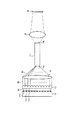
図1及び図2は、本発明の第1の一実施例を説明するための図で、照明光学系の上面概略構成を図1に、側面概略構成を図2にそれぞれ光路とともに示すもので、図1及び図2において、11はレーザアレイ、12はシリンドリカルレンズアレイ、13はコンデンサレンズ、14はカライドスコープ、15はリレーレンズ、16は被照射部である。レーザアレイ11は、そのレーザ発光部11a,11b,11c…が直線状に等ピッチで配列されている。各レーザ発光部からの各々の出射光B1は拡散光として出射する。これらの出射光B1をシリンドリカルレンズアレイ12で、その一方向について平行光束化させる。図1の例ではシリンドリカルレンズアレイ12は、入射した光束を紙面に平行な方向で平行化させた光束B2として出射させる。この場合の平行光束B2は厳密に平行でなくても良い。次のコンデンサレンズ13で隣り合う光束どうしが大きな角度差で交じり合わなければ良い。すなわち、出射光束B2がある程度重なっていても角度差が小さければ問題とはならない。
【0032】
そしてコンデンサレンズ13によって、その出射光束B3がカライドスコープ14の入射側端面14aに収斂される。そしてカライドスコープ14内を進行する光束は、カライドスコープ14内で多重反射し、その出射端面14bでは光束の面内強度の分布が均一化される。この均一化された強度分布を有する光束がリレーレンズ15によって被照射部16へ照射される。
【0033】
シリンドリカルレンズアレイ12は、いわゆるレンチキュラーレンズに置き換えてもよい。シリンドリカルレンズアレイ12は、レーザアレイ11のアレイピッチと同程度のアレイピッチを有するレンズアレイで、レーザアレイの配列方向に対してレンズパワーをもっていればよい。レンチキュラーレンズを用いる場合も、同様にそのマイクロレンズのアレイピッチをレーザアレイ11のアレイピッチと同等にして同様に作用するように構成する。シリンドリカルレンズアレイ12(もしくはレンチキュラーレンズ)をレーザアレイ11の直後の光路上に置くことにより、例えばシリンドリカルレンズアレイ11を、直線状に配列したレンズアレイ(2次元のパワーをもつ)に置き換えた場合に比べて、図1で紙面厚み方向の設置許容範囲が広くなる。すなわち図1の上下方向の微調整のみを行えば良い。
【0034】
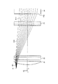
シリンドリカルレンズアレイ(またはレンチキュラーレンズ)12を使うことによって被照射部16への最大入射角を小さくできることを光線追跡計算結果を用いて説明する。図3は、レンチキュラーレンズを用いた照明光学系の効果を説明するための図で、照明光学系の概略構成を図3(A)に、図3(A)のB部の拡大図を図3(B)に示すものである。
【0035】
図3に示す構成において、実際には図1に示すごとくの光源11a,11cを含むレーザアレイが配置されるが、特徴的な光路を説明するためにレーザアレイ11の全体はその図示を省略している。すなわち図示されている光源11aはレーザアレイの端部に位置し、光源11nはレーザアレイ11の中心に位置し、その他のレーザアレイを構成する光源は、図示を省略している。レーザの光源11aの直後にはシリンドリカルレンズアレイ(またはレンチキュラーレンズ)12が配置されている。図3(B)において、12aはシリンドリカルレンズアレイ12を構成するひとつのレンズ部(シリンドリカルレンズ)で、光源11a…11nと同様にy方向にアレイ化されている。
【0036】
レーザアレイ11の光源アレイピッチとシリンドリカルレンズアレイ12の各レンズのアレイピッチ(またはレンチキュラーレンズのマイクロレンズのアレイピッチ)は同ピッチであり、図3(B)では光源11aに対応するレンチキュラー部(レンチキュラーレンズ)を構成する一つのマイクロレンズ12aのみを示している。レンチキュラーレンズ12では、各レーザアレイからの出射光は、紙面に平行な方向に平行化される。このレンチキュラーレンズ12では、レンズの球面収差のため、出射光は完全にコリメートされないが、ある程度の平行光束化で効果は十分得られる。平行光束化されたビームB2はシリンドリカルレンズ21,22,23を通過してカライドスコープ14の入射側端面14aに到達する。この場合、入射側端面14aへの最大入射角は12°である。
【0037】
シリンドリカルレンズ21は、レーザアレイ光をカライドスコープ14の入射側端面14aに偏向させるはたらきをする。シリンドリカルレンズ22,23は、レーザアレイの厚さ方向(紙面厚さ方向)の発散ビームを入射側端面14aに収斂させるはたらきをする。
【0038】
(比較例)
図4は、上記図3の構成において、レンチキュラーレンズ12が無い場合の光学系における作用を説明するための図である。図4には、図3の光学系においてレーザアレイの端部に位置する光源11aの直後のシリンドリカルレンズアレイ12を削除した場合の光線を示している。光源11aからの発散光B11はシリンドリカルレンズ21,22,23を通過してカライドスコープ14の入射側端面14aに最大入射角16°で照射される。カライドスコープ14の出射側端面(図示せず)からの出射光は、入射角度が維持されることから、最大角16°で出射される。さらに図4と図3を比較すると、シリンドリカルレンズアレイ12を用いたほうがカライドスコープ14の口径を小さくすることが可能である。同じ反射回数のカライドスコープなら口径が小さいほど全長も短くなる。したがって、シリンドリカルレンズアレイ(もしくはレンチキュラーレンズ)を用いることで照明光学系を小さくすることができる。
【0039】
(実施例2)
図5及び図6は、本発明の第2の実施例を説明するための図で、照明光学系の上面概略構成を図5に、側面概略構成を図6にそれぞれ光路とともに示すもので、照明光学系は、レンズアレイ11、シリンドリカルレンズアレイ12、カライドスコープ14、リレーレンズ15、シリンドリカルレンズ31,32,33で構成され、16は被照射部である。なお、実施例1と同様に、シリンドリカルレンズアレイ12をレンチキュラーレンズに置き換えてもよい。このとき、レンチキュラーレンズのマイクロレンズのアレイ方向やアレイピッチはシリンドリカルレンズのアレイ構成と同様とし、両者は同様に作用するように構成されるものとする。本実施例では、シリンドリカルレンズアレイ12を用いた実施例として説明する。
【0040】
シリンドリカルレンズアレイ12は、レーザアレイ11のアレイピッチと同程度のピッチでシリンドリカル面が形成されていて、図5に示すように、レーザアレイ11のアレイ方向にレンズパワーを有する。シリンドリカルレンズアレイ12によって、発散して放射される各々のレーザアレイ光B1が各々アレイ方向にのみ平行光束化される。この場合に得られる平行光束B2は、厳密に平行でなくても良い。すなわち、次のシリンドリカルレンズ31で隣り合う入射光束どうしが大きな角度差で交じり合わなければ良く、ある程度重なっていても角度差が小さければ問題ではない。
【0041】
シリンドリカルレンズアレイ12とカライドスコープ14との間の光路上には、シリンドリカルレンズが少なくとも2つ以上配置される。図5,図6ではシリンドリカルレンズが3枚で構成された例(シリンドリカルレンズ31,32,33)を示す。この場合、レーザアレイ11のアレイ方向にパワーを有する1枚のシリンドリカルレンズ32と、レーザアレイのアレイ方向の直交方向にレンズパワーを有する2枚のシリンドリカルレンズ31,33が配される。
【0042】
これらシリンドリカルレンズ31,32,33の作用について説明する。まず図5に示すように、レーザアレイ11のアレイ方向の光束については、シリンドリカルレンズ31,33が平行平板と同じであるとみなせるため、アレイ方向のみ平行光束化されたビームB2はシリンドリカルレンズ31をそのまま透過して光束B21としてシリンドリカルレンズ32に入射する。そしてその入射光束B21は、シリンドリカルレンズ32で偏向され(光束B22)、シリンドリカルレンズ33を通過して(光束B23)カライドスコープ14の入射側端面14aに到達する。
【0043】
次に図6に示すように、レーザアレイ11におけるアレイ方向と直交方向のビームについては、シリンドリカルレンズアレイ12は平行平板とみなせるため、各レーザ発光部から発散された光束B1は、シリンドリカルレンズアレイ12を透過した後も発散して光束B2となり、シリンドリカルレンズ31で平行化され(光束B21)、シリンドリカルレンズ32を通過して(光束B22)、シリンドリカルレンズ33でカライドスコープ14に収斂する(光束B23)。光束B21,B22は、図6の上下方向(すなわちレーザアレイのアレイ方向と直交方向)に平行光束である必要はない。したがって、シリンドリカルレンズ31,33を一枚のシリンドリカルレンズに置き換えて、その一枚のレンズでカライドスコープに収斂しても本発明の効果に影響を与えない。
【0044】
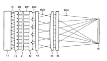
(実施例3)
図7及び図8は、本発明の第3の実施例を説明するための図で、照明光学系の上面概略構成を図7に、側面概略構成を図8にそれぞれ光路とともに示すもので、照明光学系は、レーザアレイ11、シリンドリカルレンズアレイ(もしくはレンチキュラーレンズ)12、シリンドリカルレンズ41、ホモジナイザ42,43、シリンドリカルレンズ44,45で構成される。図16は、上記のホモジナイザを用いた特開平9−234579号公報に記載されたレーザ照射装置の構成を示す上面図(図16(A))及び側面図(図16(B))で、これは線状のレーザ光を均一性を高めて線状のビームとして被照射部に照射する装置である。本実施例は、この光学系のなかで使われるホモジナイザ40a,40bを利用して、レーザアレイ光を矩形状の被照射部に均一照明させる。
【0045】
シリンドリカルレンズアレイ12(またはこれに置き換え可能なレンチキュラーレンズ)の作用は上述のとおりなのでその説明を省略する。シリンドリカルレンズ41は図8の上下方向、すなわちレーザアレイ11のアレイ方向と直交方向の発散ビーム成分を平行光束化させる(光束B31)。ホモジナイザ42は、レーザアレイ11のアレイ方向の光束を均一化させる。本実施例のホモジナイザ42は5分割の構成を有しているが、分割数が多いほど光束が均一化される。ただし、図7においてホモジナイザ42の各レンズアレイへの入射光が同じ強度分布となる場合にはホモジナイザの効果が得られない。例えば、レンチキュラーレンズ12とホモジナイザ42のアレイピッチが整数倍の関係となるときには、このような現象が生じる。ホモジナイザ42からの光(光束B32,B33)はシリンドリカルレンズ44によって被照射部16に集められる(光束B34)。
【0046】
一方、レーザアレイ11のアレイ方向と直交方向の光束においては、図8に示すように、ホモジナイザ43によって光束の強度分布が均一化される。すなわち、シリンドリカルレンズ41に入射した拡散光成分が平行光束化され(光束B31)、ホモジナイザ43で光束が分割され、その分割されたそれぞれの光束を集光させ、焦点を結んだあとさらに発散光となり(光束B33)、シリンドリカルレンズ45によって被照射部16上に重ね合わされる(光束B34)。レーザアレイ11のアレイ方向と直交方向の光束制御を行うホモジナイザ43は、その分割数が多いほど均一化の効果が高い。
【0047】
レーザアレイ11の直後にシリンドリカルレンズアレイ(レンチキュラーレンズ)12を配置することによって、アレイ方向の各アレイ光を平行光束化でき、ホモジナイザの効果を得ることができる。また、シリンドリカルレンズアレイ(もしくはレンチキュラーレンズ)であるため、レーザアレイのアイ方向と直交方向については設置精度を要求されないというメリットがある。
【0048】
(実施例4)
図9及び図10は、本発明の第4の実施例を説明するための図で、照明光学系の上面概略構成を図9に、側面概略構成を図10にそれぞれ光路とともに示すもので、照明光学系は、レーザアレイ11、シリンドリカルレンズアレイ(またはレンチキュラーレンズ)12、シリンドリカルレンズ51、フライアイレンズ52,53、コンデンサレンズ54で構成される。図示した本実施例では、2枚のフライアイレンズ52,53を用いているが、2枚目のフライアイレンズ53は必ずしも必要ではなく省略することができる。また、コンデンサレンズ54は、2枚のシリンドリカルレンズを各々のレンズパワー方向を直交させたものに置き換えても良い。なお、本実施例においても、上述の各実施例と同様に、シリンドリカルレンズアレイを同様の機能を有するレンチキュラーレンズに置き換えることができる。
【0049】
まず、図9を参照してアレイ方向の光成分に関する作用を説明する。シリンドリカルレンズアレイ12は、レーザアレイ11のアレイピッチと同程度のアレイピッチを有する。作用は前述のとおりである。シリンドリカルレンズアレイ12でレーザアレイのアレイ方向のビームがほぼ平行な光束B2となり、シリンドリカルレンズ51を通過し(光束B41)、第1フライアイレンズ52で各々のアレイ光源からの出射光束が集光される(光束B42)。第1フライアイレンズ52の焦点位置には第2フライアイレンズ53が配置される。シリンドリカルレンズアレイ12を通過した光線の図9の紙面内における進行方向が、第1フライアイレンズ52の軸に平行であれば第2フライアイレンズ53は必要ではない。またレーザアレイ11からの出射光束B1が点光源からの出射光束とみなせない場合や、シリンドリカルレンズアレイ12の収差や、シリンドリカルレンズ12におけるレーザアレイ11とのピッチずれなどによって光束B41が第1フライアイレンズ52に対してわずかに傾く。このような場合、第1フライアイレンズ52を構成する各レンズ部から集光された光線は1点に集まらないため、第2フライアイレンズ53を必要とする。そして第2フライアイレンズ53からの出射光束は、コンデンサレンズ54によって被照射部16に重ね合わされる(光束B43)。
【0050】
次に、図10を用いてレーザアレイのアレイ方向の直交方向の光束成分に関する作用を説明する。レーザアレイ11からの出射光束B1はシリンドリカルレンズアレイ12を通過して光束B2となり、シリンドリカルレンズ51で平行光束B41にされる。上述のように第1フライアイレンズ52の焦点距離位置に第2フライアイレンズ53が配されており、第1フライアイレンズ52の各レンズ部からの出射光束(光束B42)が第2フライアイレンズ53の各レンズ部を通過して、コンデンサレンズ54によって被照射部16に重ね合わされて照度均一化される(光束B43)。
【0051】
レーザアレイ11の発光部の厚さ(アレイ方向と直交方向の厚さ)が大きい場合、光束B41は第1フライアイレンズ52の光軸に対して必ずしも平行とはならず、各アレイから集光される光線は1点に集まらない。このため、第2フライアイレンズ53を用いることになる。もしレーザアレイの発光部の上記厚さが十分小さいとみなせる場合には、第1フライアイレンズ52の各レンズ部からの出射光束(光束B42)はほぼ1点に集光されるため、第2フライアイレンズ53を必要としない。シリンドリカルレンズアレイ12を用いることで、レーザアレイ11の上記厚さ方向の設置許容が広くなるというメリットがある。
【0052】
(参考例)
図11は投射装置の参考例の概略構成を光路とともに示す図で、投射装置は、上記実施例1から実施例4までのいずれかの照明光学系と、ライトバルブ、及び投射レンズとを備える。図11に示す構成例の投射装置は、照明光学系61r,61g,61bと色合成素子62とライトバルブ65と投射レンズ64とにより構成される。図11に示す構成では照明光学系61r,61g,61bとして実施例3の光学系を用いているが、上述のように照明光学系として実施例1から実施例4までのいずれの光学系を用いても良い。
【0053】
色合成素子62としては、例えばダイクロイックプリズムを用いることができる。照明光学系61r,61g,61bが、順に、赤色、緑色、青色のレーザアレイ光源である場合には、色合成素子(ダイクロイックプリズム)62はダイクロイック膜62rで赤色を反射させ、ダイクロイック膜62bで青色を反射させ、かつ、両方のダイクロイック膜62r,62bは緑色を透過させるように構成される。ライトバルブ65としては例えば液晶素子を用いることができる。図11の構成ではライトバルブの直前にフィールドレンズ63を用いている。ライトバルブ65を透過した光が投射レンズ64の瞳を通過できるはたらきをする。
【0054】
以上の構成によって、ライトバルブ65を照明する光の最大入射角は前述のとおり従来に比して低減されるため、特に液晶素子のように入射角によってコントラスト比が変化するようなライトバルブの場合、コントラスト比を向上させたり、色ムラや照度ムラを低減させることができる。
【0055】
図11では単板のライトバルブを用いた構成例を示したが、図12に示すように照明光学系61r,61g,61bに対応した計3枚のライトバルブ65r,65g,65b用いて構成しても良い。各ライトバルブ65r,65g,65bの直前に置かれているのはフィールドレンズ63r,63g,63bである。図12の構成は、図11の構成に比べて投射レンズ64とライトバルブ65r,65g,65bとの間の光路長が長くなるため、投射レンズ64のバックフォーカス長は図11の投射レンズ64のバックフォーカスより長くする必要がある。3板のライトバルブの投射装置においても、単板の場合と同様に、コントラスト比を向上させたり、色ムラや照度ムラを低減させることができる。
【0056】
図14は、露光装置の参考例について説明するための図で、図中、71は均一照明装置、72はレチクル、73は投影レンズ、74は基板ステージである。本発明の露光装置は、請求項9から請求項20までのいずれかに記載の均一照明光学装置71でレチクル72を照明し、投影レンズ73によってレチクル72のパターンが基板ステージ74に置かれたウエハーに露光されるものである。
【0057】
図15は、レーザ加工機の参考例について説明するための図で、図中、75はレンズ、76はワークである。本発明のレーザ加工機は、均一照明光学装置からの照明光をレンズ75でワーク76に集光し、加工する。ワーク76上の集光スポット形状は照明系71の被照射部のアスペクト比と同じである。集光させることでワークの微小部分にエネルギーを集中させることができ、表面加工や切断などができる。また、レンズ75を投影レンズに置き換えるか、もしくは被照射部が直接ワーク76である配置では広い範囲にわたって均一照明できるため、レーザアニールとしても利用できる。
【0058】
【発明の効果】
以上の説明から明らかなように、本発明の照明装置によれば、複数光源を用いることによってコンパクトな光学系を実現し、この光源からの拡散光を平行光化して集光することにより、照明対象部への最大入射角を小さく押さえることが可能になり、これにより種々の用途に適用した際にも良好な特性の光学システムを得ることができる。
【0059】
また、本発明の均一照明装置によれば、上記の照明装置と、光の強度分布を均一化する手段を備えることにより、簡易でかつコンパクトな均一照明可能な照明装置を得ることができる。
【図面の簡単な説明】
【図1】 本発明の第1の一実施例を説明するための図で、照明光学系の上面概略構成を示す図である。
【図2】 本発明の第1の一実施例を説明するための図で、照明光学系の側面概略構成を示す図である。
【図3】 レンチキュラーレンズを用いた照明光学系の効果を説明するための図である。
【図4】 図3の構成において、レンチキュラーレンズが無い場合の光学系における作用を説明するための図である。
【図5】 本発明の第2の実施例を説明するための図で、照明光学系の上面概略構成を示す図である。
【図6】 本発明の第2の実施例を説明するための図で、照明光学系の側面概略構成を示す図である。
【図7】 本発明の第3の実施例を説明するための図で、照明光学系の上面概略構成を示す図である。
【図8】 本発明の第3の実施例を説明するための図で、照明光学系の側面概略構成を示す図である。
【図9】 本発明の第4の実施例を説明するための図で、照明光学系の上面概略構成を示す図である。
【図10】 本発明の第4の実施例を説明するための図で、照明光学系の側面概略構成を示す図である。
【図11】 投射装置の参考例の概略構成を光路とともに示す図である。
【図12】 投射装置の他の参考例の概略構成を光路とともに示す図である。
【図13】 本発明の発光手段と平行光化手段の構成例を示す図である。
【図14】 露光装置の参考例を示す図である。
【図15】 レーザ加工機の参考例について説明するための図である。
【図16】 本発明による投射装置の他の実施例の概略構成を光路とともに示す図である。
【符号の説明】
11…レーザアレイ、12…シリンドリカルレンズアレイ、13…コンデンサレンズ、14…カライドスコープ、15…リレーレンズ、16…被照射部、31,32,33,41,44,45,51…シリンドリカルレンズ、40a,40b…ホモジナイザ、42,43…ホモジナイザ、52,53…フライアイレンズ、54…コンデンサレンズ、61r,61g,61b…照明光学系、62…色合成素子、62r,62b…ダイクロイック膜、63,63r,63g,63b…フィールドレンズ、64…投射レンズ、65,65r,65g,65b…ライトバルブ、71…均一照明装置、72…レチクル、73…投影レンズ、74…基板ステージ、75…レンズ、76…ワーク。[0001]
BACKGROUND OF THE INVENTION
The present invention relates to an illumination optical apparatus, an illumination optical system, and a projection apparatus, an exposure apparatus, and a laser processing apparatus using these, and more specifically, a plurality of light emitting means using laser array light or the like as light sources. The present invention relates to an apparatus applicable to an optical system that uniformly illuminates an irradiated portion, and to a technique applicable to a projection apparatus (projector), a stepper (exposure apparatus), and the like.
[0002]
[Prior art]
The optical system for uniformly illuminating the irradiated portion of the irradiation target is not only suitable for, for example, a light and bulb type projection device using a liquid crystal display element, a stepper used for manufacturing a semiconductor, etc. There is a need for an optical system that can be applied to various uses and has a high accuracy, a compact and simple configuration. In addition, for example, in the above-described light valve type projection device, the illumination optical system is set so that the maximum incident angle with respect to the light valve is as small as possible (that is, incident as perpendicularly as possible to the surface of the light valve). It is hoped that
[0003]
[Problems to be solved by the invention]
The present invention has been made in view of the above-described circumstances, and uses a light-emitting unit having a plurality of light sources that realizes a compact configuration. The light emitted from the plurality of light sources is uniformly and covered with respect to the irradiated surface. Illumination device for irradiating an irradiation surface with a minimum incident angle and using the same Uniform lighting device Is intended to provide.
[0004]
[Means for Solving the Problems]
According to the first aspect of the present invention, the light emitting means having a plurality of light emitting portions and the diffused light emitted from each of the light emitting portions are parallel light in at least the same direction on a plane orthogonal to the optical axis of the diffused light. And collimating means for condensing a plurality of light beams emitted from the collimating means in a predetermined condensing range. In the illumination device, the light emitting unit is configured such that the plurality of light emitting units are arranged in an array in one direction, and the collimating unit is configured by a cylindrical lens array, and each cylindrical lens configuring the cylindrical lens array The array pitch of the light emitting portions is provided to be equal to the array pitch of the light emitting portions, and the light emitted from the plurality of light emitting portions is made parallel to the divergent light component in the light source array direction by the cylindrical lens array. Characterized by being It is what.
[0006]
Claim 2 The invention of claim 1's In the present invention, the light emitting means includes a laser light emitting section that emits laser light.
[0009]
Claim 3 The invention of claim 1's In the present invention, at least two cylindrical lens arrays are provided.
[0010]
Claim 4 The invention of claim 1 In the invention, a lenticular lens is used as the collimating means, and the array pitch of each microlens constituting the lenticular lens is equal to the array pitch of the light emitting section.
[0011]
Claim 5 The invention of claim Four In the present invention, at least two or more of the lenticular lenses are provided.
[0012]
Claim 6 The invention of claim 1 to claim 1 5 Any one of the illumination device and intensity distribution uniformizing means for receiving illumination light emitted from the illumination device and uniformizing the light intensity distribution in a plane perpendicular to the optical axis of the received light. And the illumination target is illuminated by controlling the light emitted from the intensity distribution uniformizing means.
[0013]
Claim 7 The invention of claim 6 In the present invention, a kaleidoscope is used as the intensity distribution uniformizing means.
[0014]
Claim 8 The invention of claim 6 In the invention, a homogenizer is used as the intensity distribution uniformizing means.
[0015]
Claim 9 The invention of claim 6 In the invention, a fly-eye lens is used as the intensity distribution uniformizing means.
[0027]
DETAILED DESCRIPTION OF THE INVENTION
First, an essential configuration of the present invention will be described below with reference to the drawings. The configuration of the embodiment will be specifically described later with reference to the drawings again. In the illumination device of the present invention, the light emitting means 11 having a plurality of
[0028]
The light emitting means is configured such that a plurality of
[0029]
Further, a lenticular lens is used as the collimating means 11, and the array pitch of each microlens constituting the lenticular lens is made equal to the array pitch of the light emitting section. Further, at least two or more lenticular lenses may be provided.
[0030]
The uniform illumination device of the present invention receives the illumination device as described above and the illumination light emitted from the illumination device, and makes the light intensity distribution in a plane perpendicular to the optical axis of the received light uniform. It has intensity distribution uniformizing means 14 ((42, 43), (52, 53)), and illuminates the illumination target by controlling the light emitted from the intensity distribution uniformizing
[0031]
Example 1
FIGS. 1 and 2 are diagrams for explaining a first embodiment of the present invention. FIG. 1 shows a schematic top view configuration of an illumination optical system, and FIG. 2 shows a schematic side view configuration with an optical path. 1 and 2, 11 is a laser array, 12 is a cylindrical lens array, 13 is a condenser lens, 14 is a kaleidoscope, 15 is a relay lens, and 16 is an irradiated portion. In the
[0032]
Then, by the
[0033]
The
[0034]
The fact that the maximum incident angle to the irradiated
[0035]
In the configuration shown in FIG. 3, a laser array including
[0036]
The light source array pitch of the
[0037]
The
[0038]
(Comparative example)
FIG. 4 is a diagram for explaining the operation of the optical system when the
[0039]
(Example 2)
FIGS. 5 and 6 are diagrams for explaining a second embodiment of the present invention. FIG. 5 shows a schematic top view of the illumination optical system and FIG. 6 shows a schematic side view of the illumination optical system. The optical system includes a
[0040]
The
[0041]
On the optical path between the
[0042]
The operation of these
[0043]
Next, as shown in FIG. 6, since the
[0044]
(Example 3)
FIGS. 7 and 8 are diagrams for explaining a third embodiment of the present invention. FIG. 7 shows a schematic top view of the illumination optical system and FIG. 8 shows a schematic side view of the illumination optical system. The optical system includes a
[0045]
Since the operation of the cylindrical lens array 12 (or a lenticular lens that can be replaced by this) is as described above, the description thereof is omitted. The
[0046]
On the other hand, as shown in FIG. 8, the intensity distribution of the light beam is made uniform by the
[0047]
By arranging a cylindrical lens array (lenticular lens) 12 immediately after the
[0048]
Example 4
FIGS. 9 and 10 are views for explaining a fourth embodiment of the present invention. FIG. 9 shows a schematic top view of the illumination optical system, and FIG. 10 shows a schematic side view of the illumination optical system. The optical system includes a
[0049]
First, the operation relating to the light component in the array direction will be described with reference to FIG. The
[0050]
Next, the effect | action regarding the light beam component of the orthogonal | vertical direction of the array direction of a laser array is demonstrated using FIG. The emitted light beam B1 from the
[0051]
When the thickness of the light emitting portion of the laser array 11 (thickness in the direction orthogonal to the array direction) is large, the light beam B41 is not necessarily parallel to the optical axis of the first fly-
[0052]
( Reference example )
FIG. Throw Shooting equipment reference FIG. 2 is a diagram illustrating a schematic configuration of an example together with an optical path, and the projection apparatus includes any one of the illumination optical systems from Example 1 to Example 4, a light valve, and a projection lens. The projection apparatus of the configuration example shown in FIG. 11 includes illumination
[0053]
As the
[0054]
With the above configuration, since the maximum incident angle of the light that illuminates the
[0055]
FIG. 11 shows a configuration example using a single plate light valve, but a configuration using a total of three
[0056]
FIG. , Dew Optical device Reference example It is a figure for demonstrating about 71 in the figure Is average One illumination device, 72 is a reticle, 73 is a projection lens, and 74 is a substrate stage. The exposure apparatus of the present invention illuminates the
[0057]
FIG. , Les -The processing machine Reference example In the figure, 75 is a lens, and 76 is a workpiece. The laser processing machine of the present invention , Average The illumination light from one illumination optical device is condensed on the
[0058]
【The invention's effect】
As is clear from the above description, according to the illumination device of the present invention, a compact optical system is realized by using a plurality of light sources, and the diffused light from the light sources is collimated and condensed to achieve illumination. It becomes possible to keep the maximum incident angle to the target portion small, whereby an optical system with good characteristics can be obtained even when applied to various uses.
[0059]
In addition, according to the uniform illumination device of the present invention, a simple and compact illumination device capable of uniform illumination can be obtained by providing the above illumination device and means for equalizing the light intensity distribution.
[Brief description of the drawings]
FIG. 1 is a diagram for explaining a first embodiment of the present invention, and is a diagram showing a schematic top surface configuration of an illumination optical system.
FIG. 2 is a diagram for explaining a first embodiment of the present invention and is a diagram showing a schematic side configuration of an illumination optical system.
FIG. 3 is a diagram for explaining the effect of an illumination optical system using a lenticular lens.
4 is a diagram for explaining the operation of the optical system when there is no lenticular lens in the configuration of FIG. 3;
FIG. 5 is a diagram for explaining a second embodiment of the present invention, and is a diagram showing a schematic top configuration of an illumination optical system.
FIG. 6 is a diagram for explaining a second embodiment of the present invention and is a diagram showing a schematic side configuration of an illumination optical system.
FIG. 7 is a diagram for explaining a third embodiment of the present invention, and is a diagram showing a schematic top surface configuration of an illumination optical system.
FIG. 8 is a diagram for explaining a third embodiment of the present invention, and is a diagram showing a schematic side configuration of an illumination optical system.
FIG. 9 is a diagram for explaining a fourth embodiment of the present invention and is a diagram showing a schematic top surface configuration of an illumination optical system.
FIG. 10 is a diagram for explaining a fourth embodiment of the present invention and is a diagram showing a schematic side configuration of an illumination optical system.
FIG. 11 Throw Shooting equipment reference It is a figure which shows schematic structure of an example with an optical path.
FIG. Another reference example of the projection device It is a figure which shows schematic structure with an optical path.
FIG. 13 is a diagram showing a configuration example of a light emitting unit and a collimating unit of the present invention.
FIG. 14 Exposure system reference It is a figure which shows an example.
FIG. 15 Les -The processing machine Reference example It is a figure for demonstrating.
FIG. 16 is a diagram showing a schematic configuration of another embodiment of the projection apparatus according to the present invention together with an optical path.
[Explanation of symbols]
DESCRIPTION OF
Claims (9)
Priority Applications (1)
| Application Number | Priority Date | Filing Date | Title |
|---|---|---|---|
| JP2000382751A JP4059623B2 (en) | 2000-12-15 | 2000-12-15 | Illumination device and uniform illumination device |
Applications Claiming Priority (1)
| Application Number | Priority Date | Filing Date | Title |
|---|---|---|---|
| JP2000382751A JP4059623B2 (en) | 2000-12-15 | 2000-12-15 | Illumination device and uniform illumination device |
Publications (2)
| Publication Number | Publication Date |
|---|---|
| JP2002184206A JP2002184206A (en) | 2002-06-28 |
| JP4059623B2 true JP4059623B2 (en) | 2008-03-12 |
Family
ID=18850523
Family Applications (1)
| Application Number | Title | Priority Date | Filing Date |
|---|---|---|---|
| JP2000382751A Expired - Fee Related JP4059623B2 (en) | 2000-12-15 | 2000-12-15 | Illumination device and uniform illumination device |
Country Status (1)
| Country | Link |
|---|---|
| JP (1) | JP4059623B2 (en) |
Families Citing this family (43)
| Publication number | Priority date | Publication date | Assignee | Title |
|---|---|---|---|---|
| TWI332682B (en) * | 2002-09-19 | 2010-11-01 | Semiconductor Energy Lab | Beam homogenizer and laser irradiation apparatus and method of manufacturing semiconductor device |
| JP4568480B2 (en) * | 2002-12-04 | 2010-10-27 | 株式会社リコー | Information display device |
| JP4494045B2 (en) * | 2003-03-11 | 2010-06-30 | 株式会社半導体エネルギー研究所 | Beam homogenizer, laser irradiation apparatus, and method for manufacturing semiconductor device |
| US7327916B2 (en) | 2003-03-11 | 2008-02-05 | Semiconductor Energy Laboratory Co., Ltd. | Beam Homogenizer, laser irradiation apparatus, and method of manufacturing a semiconductor device |
| SG137674A1 (en) | 2003-04-24 | 2007-12-28 | Semiconductor Energy Lab | Beam homogenizer, laser irradiation apparatus, and method for manufacturing semiconductor device |
| US7245802B2 (en) | 2003-08-04 | 2007-07-17 | Semiconductor Energy Laboratory Co., Ltd. | Beam homogenizer, laser irradiation apparatus and method for manufacturing semiconductor device |
| US7169630B2 (en) | 2003-09-30 | 2007-01-30 | Semiconductor Energy Laboratory Co., Ltd. | Beam homogenizer, laser irradiation apparatus, and method for manufacturing semiconductor device |
| JP2005300712A (en) * | 2004-04-08 | 2005-10-27 | Nikon Corp | Projection type display device |
| JP2006010741A (en) * | 2004-06-22 | 2006-01-12 | Plus Vision Corp | Light source device including light emitting element and image display device using same |
| JP2006073250A (en) * | 2004-08-31 | 2006-03-16 | Harison Toshiba Lighting Corp | Lighting system |
| JP4731142B2 (en) * | 2004-09-16 | 2011-07-20 | 株式会社リコー | Color display device, projector, and eyepiece type display device |
| US7387954B2 (en) | 2004-10-04 | 2008-06-17 | Semiconductor Energy Laboratory Co., Ltd. | Beam homogenizer, laser irradiation apparatus, and method for manufacturing semiconductor device |
| EP1805548B1 (en) | 2004-10-27 | 2013-05-29 | Semiconductor Energy Laboratory Co., Ltd. | Beam homogenizer, and laser irradiation method, laser irradiation apparatus, and laser annealing method of non-single crystalline semiconductor film using the same |
| JP2008526511A (en) * | 2005-01-04 | 2008-07-24 | リモ パテントフェルヴァルトゥング ゲーエムベーハー ウント コー.カーゲー | Beam splitter |
| JP4843344B2 (en) | 2005-03-18 | 2011-12-21 | 株式会社リコー | Illumination device and image reading device |
| US7433568B2 (en) | 2005-03-31 | 2008-10-07 | Semiconductor Energy Laboratory Co., Ltd. | Optical element and light irradiation apparatus |
| JP4964876B2 (en) * | 2005-06-08 | 2012-07-04 | リモ パテントフェルヴァルトゥング ゲーエムベーハー ウント コー.カーゲー | Light irradiation device for polarization of alkali atoms and device for hyperpolarization of noble gases |
| JP4821204B2 (en) * | 2005-07-22 | 2011-11-24 | セイコーエプソン株式会社 | LIGHTING DEVICE, IMAGE DISPLAY DEVICE, AND PROJECTOR |
| JP4890169B2 (en) * | 2006-09-15 | 2012-03-07 | 株式会社リコー | Lighting device |
| JP2008234908A (en) * | 2007-03-19 | 2008-10-02 | Nec Lighting Ltd | Led spotlight |
| JP5028173B2 (en) * | 2007-07-19 | 2012-09-19 | 三洋電機株式会社 | Illumination device, projection display device, and fly-eye lens |
| JP4353992B2 (en) * | 2007-08-23 | 2009-10-28 | 三菱電機株式会社 | Illumination light source device and image display device |
| JP4670876B2 (en) * | 2008-02-14 | 2011-04-13 | 三菱電機株式会社 | Illumination optical system and image display device |
| KR100937864B1 (en) * | 2008-03-14 | 2010-01-21 | 삼성모바일디스플레이주식회사 | Frit sealing system |
| JP5248903B2 (en) * | 2008-04-18 | 2013-07-31 | リコー光学株式会社 | Line illumination device, line illumination method, optical inspection device, and optical processing device |
| JP5197227B2 (en) | 2008-08-19 | 2013-05-15 | キヤノン株式会社 | Illumination optical system and image projection apparatus |
| JP5121771B2 (en) * | 2008-09-19 | 2013-01-16 | 三菱電機株式会社 | Light source unit and image display device |
| JP2010097178A (en) * | 2008-09-22 | 2010-04-30 | Mitsubishi Electric Corp | Light source unit and image display apparatus |
| JP4788839B2 (en) * | 2010-12-01 | 2011-10-05 | セイコーエプソン株式会社 | LIGHTING DEVICE, IMAGE DISPLAY DEVICE, AND PROJECTOR |
| JP2011128634A (en) * | 2011-01-19 | 2011-06-30 | Mitsubishi Electric Corp | Lighting optical system and image display apparatus |
| JP2013015762A (en) * | 2011-07-06 | 2013-01-24 | Sony Corp | Illumination optical system and image display apparatus |
| JP5948991B2 (en) | 2012-03-13 | 2016-07-06 | 富士ゼロックス株式会社 | Fixing apparatus and image forming apparatus |
| CN107420789B (en) | 2012-11-14 | 2020-07-07 | 科勒克斯有限责任公司 | Artificial lighting device for generating natural light |
| WO2014076218A1 (en) | 2012-11-14 | 2014-05-22 | Light In Light S.R.L. | Illumination device synthesizing light from an object at virtually infinite distance |
| JP6285650B2 (en) * | 2013-07-03 | 2018-02-28 | 浜松ホトニクス株式会社 | Laser equipment |
| JP6287157B2 (en) * | 2013-12-13 | 2018-03-07 | 大日本印刷株式会社 | Illumination device and projection device |
| JP5804101B2 (en) * | 2014-02-12 | 2015-11-04 | ウシオ電機株式会社 | Laser light source device and image projection device |
| JP2015155950A (en) * | 2014-02-20 | 2015-08-27 | 大日本印刷株式会社 | Illumination device and projection device |
| JP2016057644A (en) * | 2015-12-25 | 2016-04-21 | ソニー株式会社 | Illumination optical system and image display apparatus |
| JP2017151449A (en) * | 2017-03-28 | 2017-08-31 | ソニー株式会社 | Illumination optical system and image display apparatus |
| JP2019128581A (en) * | 2018-07-13 | 2019-08-01 | セジン オント インクSEJIN ONT Inc. | Light source device and exposure apparatus including the same |
| JP7086813B2 (en) * | 2018-10-16 | 2022-06-20 | 東レエンジニアリング株式会社 | Lighting equipment |
| KR102197383B1 (en) * | 2020-07-27 | 2020-12-31 | 써니파이브 주식회사 | Lighting device for providing light similar to natural light |
-
2000
- 2000-12-15 JP JP2000382751A patent/JP4059623B2/en not_active Expired - Fee Related
Also Published As
| Publication number | Publication date |
|---|---|
| JP2002184206A (en) | 2002-06-28 |
Similar Documents
| Publication | Publication Date | Title |
|---|---|---|
| JP4059623B2 (en) | Illumination device and uniform illumination device | |
| CN107065410B (en) | Projection type image display device | |
| JP6424827B2 (en) | Light source device, light source unit, and image display device | |
| US8330938B2 (en) | Solid-state array for lithography illumination | |
| KR20140123421A (en) | Light source device and exposure device | |
| USRE34634E (en) | Light illumination device | |
| JP7116368B2 (en) | Illumination apparatus and method, exposure apparatus and method, and device manufacturing method | |
| KR102144863B1 (en) | Illuminating apparatus, exposure apparatus, exposure method and device manufacturing method | |
| US10606157B2 (en) | Illuminator and projector | |
| CN218974749U (en) | Photographic lamp | |
| US20070058149A1 (en) | Lighting system and exposure apparatus | |
| WO2021098450A1 (en) | Light source system and light-emitting device | |
| WO2017043185A1 (en) | Light source device | |
| JP2021167911A (en) | Light source device, projector, and machining device | |
| CN112969969B (en) | Light source device for exposure | |
| WO2020116086A1 (en) | Light source device for exposure | |
| JP4004601B2 (en) | Illumination optical system of exposure equipment | |
| WO2020116081A1 (en) | Light source device for exposure | |
| JP3406946B2 (en) | Illumination optical system, optical apparatus using the same, and device manufacturing method using the optical apparatus | |
| JP2023171460A (en) | Fly-eye lens and illumination optical device | |
| JP2023006187A (en) | Illumination device, microscope and illumination method | |
| JPH08162402A (en) | Illuminating optical system | |
| JPH07321022A (en) | Illumination optical system | |
| JP2001210586A (en) | Illumination optical system, projection exposure system, method of manufacturing semiconductor device, and exposure method | |
| JPS62266532A (en) | Illuminating optical system |
Legal Events
| Date | Code | Title | Description |
|---|---|---|---|
| A621 | Written request for application examination |
Free format text: JAPANESE INTERMEDIATE CODE: A621 Effective date: 20050113 |
|
| A131 | Notification of reasons for refusal |
Free format text: JAPANESE INTERMEDIATE CODE: A131 Effective date: 20070925 |
|
| A521 | Written amendment |
Free format text: JAPANESE INTERMEDIATE CODE: A523 Effective date: 20071121 |
|
| TRDD | Decision of grant or rejection written | ||
| A01 | Written decision to grant a patent or to grant a registration (utility model) |
Free format text: JAPANESE INTERMEDIATE CODE: A01 Effective date: 20071218 |
|
| A61 | First payment of annual fees (during grant procedure) |
Free format text: JAPANESE INTERMEDIATE CODE: A61 Effective date: 20071218 |
|
| FPAY | Renewal fee payment (event date is renewal date of database) |
Free format text: PAYMENT UNTIL: 20101228 Year of fee payment: 3 |
|
| R150 | Certificate of patent or registration of utility model |
Free format text: JAPANESE INTERMEDIATE CODE: R150 |
|
| FPAY | Renewal fee payment (event date is renewal date of database) |
Free format text: PAYMENT UNTIL: 20101228 Year of fee payment: 3 |
|
| FPAY | Renewal fee payment (event date is renewal date of database) |
Free format text: PAYMENT UNTIL: 20111228 Year of fee payment: 4 |
|
| FPAY | Renewal fee payment (event date is renewal date of database) |
Free format text: PAYMENT UNTIL: 20111228 Year of fee payment: 4 |
|
| FPAY | Renewal fee payment (event date is renewal date of database) |
Free format text: PAYMENT UNTIL: 20121228 Year of fee payment: 5 |
|
| FPAY | Renewal fee payment (event date is renewal date of database) |
Free format text: PAYMENT UNTIL: 20131228 Year of fee payment: 6 |
|
| LAPS | Cancellation because of no payment of annual fees |