JP4053900B2 - Protective tube closure and protective tube device - Google Patents
Protective tube closure and protective tube device Download PDFInfo
- Publication number
- JP4053900B2 JP4053900B2 JP2003033391A JP2003033391A JP4053900B2 JP 4053900 B2 JP4053900 B2 JP 4053900B2 JP 2003033391 A JP2003033391 A JP 2003033391A JP 2003033391 A JP2003033391 A JP 2003033391A JP 4053900 B2 JP4053900 B2 JP 4053900B2
- Authority
- JP
- Japan
- Prior art keywords
- protective tube
- engaging portion
- crack
- peripheral wall
- longitudinal direction
- Prior art date
- Legal status (The legal status is an assumption and is not a legal conclusion. Google has not performed a legal analysis and makes no representation as to the accuracy of the status listed.)
- Expired - Fee Related
Links
Images


Landscapes
- Protection Of Pipes Against Damage, Friction, And Corrosion (AREA)
- Rigid Pipes And Flexible Pipes (AREA)
- Details Of Indoor Wiring (AREA)
Description
【0001】
【発明の属する技術分野】
この発明は、配線・配管材を収容する保護管を閉じた状態に保持する閉じ具、および保護管装置に関するものである。
【0002】
【従来の技術】
従来、例えば、図9に示されるように、ヒンジ11aを介して連結されてなる半管状の二つの分割体11b、11bによって構成される波付管からなる保護管11において、その分割体11b、11bの合わさる部分11cの開きを防止するための閉じ具として、全体がC字形状をした閉じ具12が知られていた(例えば、特許文献1参照)。この閉じ具12は、内面に、保護管11の谷部11dに係合する突起12aを備えており、保護管11の外面に取り付けることにより、その保護管11の開きを防止するものであった。
【0003】
【特許文献1】
実開平7−3229号公報
【0004】
【発明が解決しようとする課題】
しかしながら、前記従来の閉じ具12にあっては、保護管11の開きを防止することはできるものの、分割体11b、11bの合わさる部分11cで、山谷の位置が一致していると、一方の分割体11bが他方の分割体11bの内側に入り込んで、保護管11が潰れる虞があった(図10参照)。
【0005】
また、円筒状に形成された保護管11の場合には、閉じ具12が保護管11の周方向に沿って回動してしまい、その結果、保護管11の合わさった部分11cが、簡単に開いてしまうという問題があった。
【0006】
この発明は、上記した従来の欠点を解決するためになされたものであり、その目的とするところは、保護管の潰れを防止することができる、保護管の閉じ具、および保護管装置を提供することにある。
【0007】
また、他の目的は、保護管の周方向に沿って回動するのを阻止して、保護管の開きを確実に防止することができる、保護管の閉じ具、および保護管装置を提供することにある。
【0008】
【課題を解決するための手段】
この発明に係る保護管の閉じ具、および保護管装置は、前記目的を達成するために、次の構成からなる。すなわち、
請求項1に記載の発明に係る保護管の閉じ具は、長手方向に山谷が連続して並んで形成された周壁を有し内部に配線・配管材を収容する保護管の、長手方向に連続して割れた割れ部を閉じた状態に保持する閉じ具である。この閉じ具は、前記周壁における前記割れ部部分の対向する端部を、それら端部における前記山谷の位置を前記長手方向に相対的にずらすべく、前記保護管と係合する係合部を備える。
【0009】
この保護管は、長手方向に連続して割れた割れ部を有しており、この割れ部を開くことで、配線・配管材を保護管の内部に収容することができる。そして、この保護管は、閉じ具によって、割れ部が閉じた状態に保持される。このとき、閉じ具は、保護管と係合する係合部を備えており、この係合によって、保護管の周壁における割れ部部部分の対向する端部は、それら端部における山谷の位置が長手方向に相対的にずれる。このように、割れ部部分の対向する端部が、山谷の位置が長手方向に相対的にずれることで、一方の端部が、他方の端部の下に潜り込むのを防ぐことができる。
【0010】
また、請求項2に記載の発明に係る保護管の閉じ具のように、請求項1に記載の閉じ具において、前記係合部は、前記周壁の山谷によって形成される凹条部に係合し、かつ、前記係合部は、前記割れ部によって分断された一方側の前記凹条部に係合する第1係合部と、他方側の前記凹条部に係合する第2係合部とからなってもよい。ここで、前記第1係合部と前記第2係合部とは、前記周壁における前記割れ部部分の対向する端部を、前記長手方向に相対的にずらすように、位置がずれて形成されてなる。これにより、閉じ具の第1係合部が、保護管における割れ部によって分断された一方側の凹条部に係合し、閉じ具の第2係合部が、他方側の凹条部に係合することで、周壁における割れ部部分の対向する端部は、それら端部における山谷の位置が長手方向に相対的にずれることとなる。
【0011】
また、請求項3に記載の発明に係る保護管の閉じ具のように、請求項2に記載の閉じ具において、前記第2係合部は、一方側の前記端部の端面に当接する第1当接部を有し、前記第1係合部は、他方側の前記端部の端面に当接する第2当接部を有してもよい。こうして、閉じ具の第1および第2係合部が、周壁における割れ部部分の対向する端部の各端面に当接することで、この閉じ具は、保護管に対して回り止めされる。
【0012】
また、請求項4に記載の発明に係る保護管の閉じ具のように、請求項1ないし3のいずれか1項に記載の閉じ具において、前記閉じ具は、前記保護管に取り付けられるべく、前記周壁をその周方向に180°を越えて覆うように延設されていてもよい。こうして、閉じ具は、保護管の周壁をその周方向に180°を越えて覆うことで、この保護管に取り付けられ、その取付けが確実となる。
【0013】
また、請求項5に記載の発明に係る保護管装置は、請求項1ないし4のいずれか1項に記載の閉じ具と、前記保護管とからなる。
【0014】
また、請求項6に記載の発明に係る保護管装置のように、請求項5に記載の保護管装置において、前記保護管は、前記割れ部を開閉可能とすべく、ヒンジ部を備えてもよい。こうして、保護管は、ヒンジ部を備えることから、割れ部は、簡単に開閉される。
【0015】
また、請求項7に記載の発明に係る保護管装置のように、請求項5に記載の保護管装置において、前記保護管は、前記割れ部が二ヵ所に設けられ、それら割れ部によって分離された、二つの独立した分割体からなってもよい。こうして、保護管は、二つの独立した分割体からなることから、割れ部は、簡単に開閉される。
【0016】
【発明の実施の形態】
以下、この発明に係る保護管の閉じ具、および保護管装置の実施の形態を図面に基づいて説明する。
【0017】
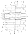
図1ないし図6は、本発明に係る保護管の閉じ具、および保護管装置の第一の実施の形態を示す。図中符号1は、配線・配管材であって、配線材として、例えば、送電用とか通信用等のケーブルであったり、また、配管材として、例えば、エアコン用の冷媒管等であったりする。2は、内部に前記配線・配管材1を収容して保護する保護管である。3は、前記保護管2に取り付けられる閉じ具である。4は、保護管装置であって、前記保護管2と前記閉じ具3とからなる。
【0018】
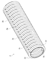
ここで、保護管2は、例えばポリエチレン樹脂製であって、円筒形状をしている。この保護管2は、長手方向に山谷が連続して並んで形成された周壁2aを有する、可撓性を備えたコルゲート管からなる。そして、保護管2は、長手方向に連続して割れた割れ部2bを有している。また、保護管2は、例えば割れ部2bと対向する側に、割れ部2bを開閉可能とすべく、ヒンジ部2cを備えている。こうして、保護管2は、前記ヒンジ部2cを介して連結される、半管状の二つの分割体2d、2dにより構成されることとなる。詳細には、ヒンジ部2cは、周壁2aの山谷における頂部2e、2eを残して切断されることで形成されている。そして、このように、保護管2は、ヒンジ部2cによって、前記割れ部2bが、開閉可能となり、この割れ部2bから、配線・配管材1が出し入れされる。しかも、保護管2は、このヒンジ部2cを備えることから、割れ部2bが、簡単に開閉される。
【0019】
閉じ具3は、前記保護管2の割れ部2bを閉じた状態に保持するものである。この閉じ具3は、保護管2の周壁2aにおける前記割れ部2b部分の対向する端部2f、2fを、それら端部2f、2fにおける前記山谷の位置を保護管2の長手方向に相対的にずらすべく(言い換えれば、それら端部2f、2fにおける前記山谷の位相が異なるように、保護管2の長手方向に相対的にずらすべく)、その保護管2と係合する係合部3aを備えている。
【0020】
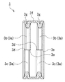
詳細には、係合部3aは、前記保護管2における周壁2aの山谷によって形成される凹条部2gに係合する。そして、この係合部3aは、割れ部2bによって分断された一方側の凹条部2gに係合する第1係合部3bと、他方側の凹条部2gに係合する第2係合部3cとからなる。ここにおいて、第1係合部3bと第2係合部3cとは、保護管2の周壁2aにおける割れ部2b部分の対向する端部2f、2fを、保護管2の長手方向に相対的にずらすように、位置がずれて形成されている。また、第2係合部3cは、一方側の前記端部2fの端面2hに当接する第1当接部3dを有する。同様にして、第1係合部3bは、他方側の前記端部2fの端面2hに当接する第2当接部3eを有する。
【0021】
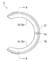
より詳細には、閉じ具3は、例えばポリ塩化ビニール等の合成樹脂製等、弾性変形可能な材料からなる。そして、閉じ具3は、保護管2に取り付けられるべく、保護管2の周壁2aをその周方向に180°を越えて(図示実施の形態においては、約240°の範囲で)覆うように延設されている。すなわち、閉じ具3は、略C字形状をしている。そして、閉じ具3は、両端部分が、保護管2の径を越えるように弾性的に開くことで、保護管2に取付け可能となっている。
【0022】
具体的には、閉じ具3は、帯状の円弧形状に形成された、本体部3fと、その本体部3fの内側から突出する前記係合部3a(図示実施の形態においては、二本の係合部3a、3a)とからなる。この係合部3a(第1係合部3b、第2係合部3c)は、前記凹条部2gに、その凹条部2gに沿って係合するように、周壁2aの周方向に延設されて形成されている。そして、係合部3aは、その延設されたほぼ中央部分で、前記第1係合部3bと前記第2係合部3cとに分かれ、そして、第1係合部3bと第2係合部3cとが、保護管2の長手方向に相対的にずれることで表われる端面が、第1係合部3b側の前記第2当接部3eとなり、そして、第2係合部3c側の前記第1当接部3dとなっている。なお、図中符号3gは、閉じ具3(本体部3f)の外周面に形成された肉抜き用の溝である。
【0023】
次に、以上の構成からなる閉じ具3、および、この閉じ具3と保護管2とからなる保護管装置4の作用効果について説明する。保護管2は、長手方向に連続して割れた割れ部2bを有しており、この割れ部2bを開くことで、配線・配管材1を保護管2の内部に収容することができる。そして、保護管2は、閉じ具3によって、割れ部2bが閉じた状態に保持される。このとき、閉じ具3は、保護管2と係合する係合部3a(具体的には、保護管2の凹条部2gに係合する係合部3a)を備えており、この係合によって、保護管2の周壁2aにおける割れ部2b部部分の対向する端部2f、2fは、それら端部2f、2fにおける山谷の位置が保護管2の長手方向に相対的にずれる。すなわち、閉じ具3の第1係合部3bが、保護管2における割れ部2bによって分断された一方側の凹条部2gに係合し、閉じ具3の第2係合部3cが、他方側の凹条部2gに係合することで、周壁2aにおける割れ部2b部分の対向する端部2f、2fは、それら端部2f、2fにおける山谷の位置が保護管2の長手方向に相対的にずれることとなる。そして、このように、割れ部2b部分の対向する端部2f、2fが、山谷の位置が保護管2の長手方向に相対的にずれることで、一方の端部2fが、他方の端部2fの下に潜り込むのを防ぐことができ、これにより、保護管2の潰れを防止することができる。もっとも、この山谷の位置のずれは、この保護管2の周壁2aの肉厚よりも小さいのが望ましい。すなわち、このように、このずれを周壁2aの肉厚よりも小さくすることで、端部2f、2fがずれたことにより周壁2aの端面2h、2hの内側に孔が開くのを防止することができる。
【0024】
また、このとき、閉じ具3の第1および第2の係合部3b、3cが、保護管2の周壁2aにおける割れ部2b部分の対向する端部2f、2fの各端面2h、2hに当接することで、この閉じ具3は、保護管2に対して回り止めされる。したがって、この閉じ具3が、保護管2の周方向に沿って回動するのを阻止することができ、このことから、閉じ具3を、保護管2の所定の位置に保つことができる。そして、このように、閉じ具3が、保護管2の所定の位置に保たれることから、保護管2の開きを確実に防止することができる。
【0025】
また、閉じ具3は、保護管2の周壁2aをその周方向に180°を越えて覆うことで、この保護管2に取り付けられるというように、その取付けが確実に行なわれる。
【0026】
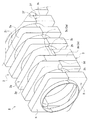
図7および図8は、本発明に係る保護管の閉じ具、および保護管装置の第二の実施の形態を示す。この実施の形態においては、保護管2の割れ部2bが二ヵ所に設けられ、そして、それに対応して、閉じ具3の形状が異なるが、他はほぼ同様であり、以下に、異なる部分を主に説明する。
【0027】
保護管2は、長手方向に山谷が連続して並んで形成された周壁2aを有するが、この山谷における頂部2e、2eを連ねた形状は、略四角筒形状をしており、また、山谷における底部2i、2iを連ねた形状は、円筒形状をしている。そして、保護管2は、前述のように、保護管2の長手方向に連続して割れた割れ部2bが、二ヵ所に設けられ、こうして、保護管2は、それら割れ部2b、2bによって分離された、二つの独立した分割体H、Hからなっている。そして、このように、保護管2は、二つの独立した分割体H、Hに分離されることで、その分離した割れ部2b、2bから、配線・配管材が出し入れされる。
【0028】
一方、閉じ具3は、第一の実施の形態に示す本体部3fに相当する部分は無く、保護管2の周壁2aの山谷によって形成される凹条部2gに係合する、係合部3a(第1係合部3b、第2係合部3c)のみによって形成されている。具体的には、閉じ具3は、その外周が、保護管2の周壁2aの山谷における頂部2eとほぼ面一となって、略コの字形状をし、そして、その内周が、前記山谷における底部2iとほぼ一致して、略C字形状をしている。こうして、閉じ具3は、保護管2の周壁2aをその周方向に180°を超えて覆うように延設され、そして、保護管2の周壁2aの山谷によって形成される凹条部2gに、ちょうど嵌る形状となっている。そして、閉じ具3(係合部3a)の中間部分が、前記第1係合部3bとなり、閉じ具3(係合部3a)の各先端部分が、前記第2係合部3cとなっている。すなわち、第1係合部3bが、保護管2における一方の分割体Hの凹条部2g全長に渡って係合し、第2係合部3cが、他方の分割体Hの、端部2f部分における凹条部2gのみに係合している。こうして、第1係合部3bは、割れ部2bによって分断された一方側の凹条部2gに係合し、第2係合部3cは、他方側の凹条部2gに係合することとなる。そして、第1係合部3bと第2係合部3cとは、保護管2の周壁2aにおける割れ部2b部分の対向する端部2f、2fを(図示実施の形態においては、一方の分割体Hと他方の分割体Hとを)、それら端部2f、2fにおける前記山谷の位置を保護管2の長手方向に相対的にずらすよう、位置がずれて形成されている。そして、第一の実施の形態と同様に、第2係合部3cは、一方側の端部2fの端面2hに当接する第1当接部3dを有し、そして、第1係合部3bは、他方側の端部2fの端面2hに当接する第2当接部3eを有している。
【0029】
この第二の実施の形態に示す、閉じ具3および保護管装置4の作用効果は、第一の実施の形態と同様であるが、特に、保護管2は、二つの独立した分割体H、Hからなることから、割れ部2b、2bが、より簡単に開閉される。そして、保護管2は、その外形形状が、略四角筒形状をしており、配置面に、安定よく配置される。
【0030】
なお、本発明は、上述した実施の形態に限定されるわけではなく、その他種々の変更が可能である。例えば、第一の実施の形態において、保護管2は、ヒンジ部2cが、周壁2aの周方向の一ヶ所に設けられているが、二ヶ所等、複数ヶ所に設けられてもよい。
【0031】
また、第一の実施の形態において、閉じ具3における、係合部3aを構成する第1係合部3bや第2係合部3cは、周壁2aの周方向に延設されて形成されなくとも、分断されて形成される等、その他の形状に形成されていてもよい。
【0032】
また、第一の実施の形態において、閉じ具3は、本体部3fを備えているが、この本体部3fを備えることなく、係合部3aのみによって形成されてもよい。反対に、第二の実施の形態において、閉じ具3は、係合部3aのみによって形成されなくとも、第一の実施の形態と同様に、本体部3fを備えることで、係合部3aが本体部3fから突出するように形成されてもよい。
【0033】
また、第一あるいは第二の実施の形態において、閉じ具3は、第1および第2の当接部3d、3eを備えているが、この当接部3d、3eは、無くともよい。
【0034】
また、第一の実施の形態においては、保護管2は、ヒンジ部2cによって、割れ部2bが開閉可能となり、また、第二の実施の形態においては、保護管2は、独立した分割体H、Hからなることで、割れ部2b、2bが開閉可能となるが、これらの構成を採ることなく、割れ部2bが開閉可能となるように、保護管2が柔軟性を備えているのであれば、これらの構成は必ずしも必要ではない。
【0035】
また、保護管2における周壁2aの山谷は、リング状に形成されていてもよく、勿論、螺旋状に形成されていてもよい。
【0036】
【発明の効果】
以上、詳述したところから明らかなように、この発明に係る保護管の閉じ具、および保護管装置によれば、次の効果がある。
【0037】
請求項1に記載された保護管の閉じ具、および、請求項5ないし7に記載された保護管装置によれば、保護管における割れ部部分の対向する端部が、山谷の位置が長手方向に相対的にずれることで、一方の端部が、他方の端部の下に潜り込むのを防ぐことができ、保護管の潰れを防止することができる。
【0038】
また、請求項2に記載された保護管の閉じ具によれば、請求項1の効果に加えて、保護管の凹条部に係合する、第1係合部および第2係合部により、保護管の周壁における割れ部部分の対向する端部を、長手方向に相対的にずらすことができる。
【0039】
また、請求項3に記載された保護管の閉じ具によれば、請求項2の効果に加えて、閉じ具の第1および第2の係合部が、周壁における割れ部部分の対向する端部の各端面に当接することで、この閉じ具は、保護管に対して回り止めされるので、この閉じ具が、保護管の周方向に沿って回動するのを阻止することができる。そして、このことから、閉じ具を、保護管の所定の位置に保つことができ、保護管の開きを確実に防止することができる。
【0040】
また、請求項4に記載された保護管の閉じ具によれば、請求項1ないし3のいずれか1項の効果に加えて、閉じ具が、保護管の周壁をその周方向に180°を越えて覆うことで、保護管への閉じ具の取付けを確実に行なうことができる。
【図面の簡単な説明】
【図1】この発明に係る保護管の閉じ具、および保護管装置の第一の実施の形態の、断面図である。
【図2】同じく、図1における、閉じ具の一部を破断したA矢視図である。
【図3】同じく、保護管の斜視図である。
【図4】同じく、保護管の開いた状態を示す断面図である。
【図5】同じく、閉じ具の正面図である。
【図6】同じく、図5におけるB−B線による断面図である。
【図7】この発明に係る保護管の閉じ具、および保護管装置の第二の実施の形態の、分解斜視図である。
【図8】同じく、組んだ状態を示す斜視図である。
【図9】従来の閉じ具および保護管の、正面図である。
【図10】同じく、分割体の合わさる部分で一方の分割体が他方の分割体の内側に入り込んだ状態を示す正面図である。
【符号の説明】
1 配線・配管材 2 保護管
2a 周壁 2b 割れ部
2c ヒンジ部 2f 端部
2g 凹条部 2h 端面
3 閉じ具 3a 係合部
3b 第1係合部 3c 第2係合部
3d 第1当接部 3e 第2当接部
4 保護管装置
H 分割体[0001]
BACKGROUND OF THE INVENTION
The present invention relates to a closing tool for holding a protective tube for housing wiring / piping material in a closed state, and a protective tube device.
[0002]
[Prior art]
Conventionally, for example, as shown in FIG. 9, in a
[0003]
[Patent Document 1]
Japanese Utility Model Publication No. 7-3229
[Problems to be solved by the invention]
However, in the
[0005]
Further, in the case of the
[0006]
The present invention has been made to solve the above-described conventional drawbacks, and an object of the present invention is to provide a protective tube closing device and a protective tube device that can prevent the protective tube from being crushed. There is to do.
[0007]
Another object of the present invention is to provide a protective tube closing device and a protective tube device that prevent rotation of the protective tube along the circumferential direction of the protective tube and reliably prevent the protective tube from opening. There is.
[0008]
[Means for Solving the Problems]
In order to achieve the above object, a protective tube closing device and a protective tube device according to the present invention have the following configuration. That is,
The protective tube closing device according to the invention of
[0009]
The protective tube has a crack portion that is continuously cracked in the longitudinal direction, and the wiring / pipe material can be accommodated inside the protective tube by opening the crack portion. And this protection tube is hold | maintained in the state which the crack part closed by the closing tool. At this time, the closing tool is provided with an engaging portion that engages with the protective tube, and by this engagement, the opposing end portions of the cracked portion portion of the peripheral wall of the protective tube are positioned at the positions of the peaks and valleys at these end portions. It shifts relatively in the longitudinal direction. In this way, the opposite end portions of the cracked portion portions can be prevented from sinking under one end portion of the other end portion due to the relative shift of the positions of the peaks and valleys in the longitudinal direction.
[0010]
In addition, like the protective tube closing device according to
[0011]
Further, like the protective tube closing device according to the third aspect, in the closing device according to the second aspect, the second engagement portion is a first member that contacts the end surface of the one end portion. 1 contact part may be provided, and the 1st engaging part may have the 2nd contact part contact | abutted to the end surface of the said other edge part. In this way, the first and second engaging portions of the closing tool abut against the respective end surfaces of the opposing end portions of the crack portion in the peripheral wall, so that the closing tool is prevented from rotating with respect to the protective tube.
[0012]
Further, like the protective tube closing device according to
[0013]
According to a fifth aspect of the present invention, a protective tube device includes the closing device according to any one of the first to fourth aspects and the protective tube.
[0014]
Further, like the protective tube device according to the invention described in claim 6, in the protective tube device according to claim 5, the protective tube may include a hinge portion so that the crack portion can be opened and closed. Good. Thus, since the protective tube includes the hinge portion, the crack portion can be easily opened and closed.
[0015]
Further, as in the protective tube device according to the invention described in claim 7, in the protective tube device according to claim 5, the protective tube is provided with the cracked portions at two locations and separated by the cracked portions. It may consist of two independent divisions. Thus, since the protective tube is composed of two independent divided bodies, the crack portion can be easily opened and closed.
[0016]
DETAILED DESCRIPTION OF THE INVENTION
Embodiments of a protective tube closing device and protective tube device according to the present invention will be described below with reference to the drawings.
[0017]
1 to 6 show a first embodiment of a protective tube closure and a protective tube device according to the present invention.
[0018]
Here, the
[0019]
The
[0020]
In detail, the
[0021]
More specifically, the
[0022]
Specifically, the
[0023]
Next, the effect of the
[0024]
At this time, the first and second
[0025]
Further, the
[0026]
7 and 8 show a second embodiment of a protective tube closing device and a protective tube device according to the present invention. In this embodiment, the
[0027]
The
[0028]
On the other hand, the
[0029]
The effects of the
[0030]
In addition, this invention is not necessarily limited to embodiment mentioned above, A various other change is possible. For example, in the first embodiment, the
[0031]
In the first embodiment, the first engaging
[0032]
In the first embodiment, the
[0033]
In the first or second embodiment, the
[0034]
Further, in the first embodiment, the
[0035]
Moreover, the peaks and valleys of the
[0036]
【The invention's effect】
As is apparent from the above description, the protective tube closure and protective tube device according to the present invention have the following effects.
[0037]
According to the protective tube closing device described in
[0038]
According to the protective tube closing device of the second aspect, in addition to the effect of the first aspect, the first engaging portion and the second engaging portion that engage with the concave portion of the protective tube. The opposing ends of the cracked portion of the peripheral wall of the protective tube can be relatively shifted in the longitudinal direction.
[0039]
According to the protective tube closing device described in
[0040]
According to the protective tube closing device described in
[Brief description of the drawings]
FIG. 1 is a cross-sectional view of a first embodiment of a protective tube closure and a protective tube device according to the present invention.
2 is a view taken along arrow A in FIG. 1 in which a part of the closing tool is broken.
FIG. 3 is a perspective view of the protective tube.
FIG. 4 is a cross-sectional view showing a state in which the protective tube is opened.
FIG. 5 is also a front view of the closing tool.
6 is a cross-sectional view taken along line BB in FIG.
FIG. 7 is an exploded perspective view of a second embodiment of a protective tube closing device and a protective tube device according to the present invention.
FIG. 8 is a perspective view showing the assembled state.
FIG. 9 is a front view of a conventional closure and protective tube.
FIG. 10 is also a front view showing a state in which one divided body enters the inside of the other divided body at a portion where the divided bodies are combined.
[Explanation of symbols]
DESCRIPTION OF
Claims (7)
前記周壁における前記割れ部部分の対向する端部を、それら端部における前記山谷の位置を前記長手方向に相対的にずらすべく、前記保護管と係合する係合部を備えることを特徴とする、保護管の閉じ具。It is a closing tool that keeps the crack part continuously cracked in the longitudinal direction of the protective tube that has the peripheral wall formed by arranging the valleys continuously in the longitudinal direction and accommodates the wiring and piping materials inside. There,
An engaging portion that engages with the protective tube is provided so that the opposing ends of the cracked portion in the peripheral wall are displaced relative to the longitudinal direction in the longitudinal direction. , Protective tube closure.
前記係合部は、前記割れ部によって分断された一方側の前記凹条部に係合する第1係合部と、他方側の前記凹条部に係合する第2係合部とからなり、
前記第1係合部と前記第2係合部とは、前記周壁における前記割れ部部分の対向する端部を、前記長手方向に相対的にずらすように、位置がずれて形成されてなることを特徴とする、請求項1に記載の、保護管の閉じ具。The engaging portion engages with a concave portion formed by a mountain valley of the peripheral wall, and
The engaging portion includes a first engaging portion that engages with the concave portion on one side divided by the crack portion, and a second engaging portion that engages with the concave portion on the other side. ,
The first engaging portion and the second engaging portion are formed so as to be displaced from each other so that the opposing end portions of the crack portion in the peripheral wall are relatively displaced in the longitudinal direction. The protective tube closure according to claim 1, wherein:
前記第1係合部は、他方側の前記端部の端面に当接する第2当接部を有することを特徴とする、請求項2に記載の、保護管の閉じ具。The second engagement portion has a first contact portion that contacts the end surface of the end portion on one side,
The said 1st engaging part has a 2nd contact part contact | abutted to the end surface of the said edge part of the other side, The closure of the protective tube of Claim 2 characterized by the above-mentioned.
Priority Applications (1)
| Application Number | Priority Date | Filing Date | Title |
|---|---|---|---|
| JP2003033391A JP4053900B2 (en) | 2003-02-12 | 2003-02-12 | Protective tube closure and protective tube device |
Applications Claiming Priority (1)
| Application Number | Priority Date | Filing Date | Title |
|---|---|---|---|
| JP2003033391A JP4053900B2 (en) | 2003-02-12 | 2003-02-12 | Protective tube closure and protective tube device |
Publications (2)
| Publication Number | Publication Date |
|---|---|
| JP2004248364A JP2004248364A (en) | 2004-09-02 |
| JP4053900B2 true JP4053900B2 (en) | 2008-02-27 |
Family
ID=33019377
Family Applications (1)
| Application Number | Title | Priority Date | Filing Date |
|---|---|---|---|
| JP2003033391A Expired - Fee Related JP4053900B2 (en) | 2003-02-12 | 2003-02-12 | Protective tube closure and protective tube device |
Country Status (1)
| Country | Link |
|---|---|
| JP (1) | JP4053900B2 (en) |
Families Citing this family (1)
| Publication number | Priority date | Publication date | Assignee | Title |
|---|---|---|---|---|
| JP7097243B2 (en) * | 2018-06-27 | 2022-07-07 | 古河電気工業株式会社 | Square conduit, straight conduit laying structure, conduit laying structure, conduit laying method and square conduit laying method |
-
2003
- 2003-02-12 JP JP2003033391A patent/JP4053900B2/en not_active Expired - Fee Related
Also Published As
| Publication number | Publication date |
|---|---|
| JP2004248364A (en) | 2004-09-02 |
Similar Documents
| Publication | Publication Date | Title |
|---|---|---|
| US4986575A (en) | Plastic protective tube arrangement for lines | |
| JP2007306776A (en) | Protector for wire harness | |
| EP0933852B1 (en) | Elbow for the angular connection of two stretches of raceway for electrical cable systems | |
| EP1708328A2 (en) | Protector | |
| KR20040088571A (en) | Coupling device constitute two halves | |
| KR930014628A (en) | Glove holder unit for limited firewall | |
| BR9611702A (en) | Improved fluid conduit coupling | |
| JP2018046704A (en) | Structure for attaching grommet to vehicle body | |
| JP4053900B2 (en) | Protective tube closure and protective tube device | |
| CN111843985A (en) | Protective cover sealing member, robot and parallel connecting rod robot | |
| DK2647094T3 (en) | SOCKET FOR A FLEXIBLE WIRE IN AN INSTALLATION BOX | |
| JP2008095747A (en) | Bent part protection cover for tube | |
| TWI804542B (en) | Cutting device for cutting bellows and guide protrusion in the cutting device | |
| US4960252A (en) | Holder for fastening at least one long round body | |
| JP4066397B2 (en) | Tube connection method | |
| JPH0415388A (en) | Connecting structure of corrugated pipe and connecting fitting | |
| JP2003336789A (en) | Split corrugated pipe | |
| JPH041436Y2 (en) | ||
| JP7423713B2 (en) | Clip and annular cover | |
| JP2002165327A (en) | Protecting tube | |
| JPH0724714Y2 (en) | Corrugated tube with locking structure | |
| JP2000115942A (en) | Corrugated tube | |
| BR9911128A (en) | Removable and replaceable hub seal | |
| JP4264050B2 (en) | Protective pipe for wiring and piping materials | |
| JPH11191911A (en) | Protective tube and its manufacturing method |
Legal Events
| Date | Code | Title | Description |
|---|---|---|---|
| A621 | Written request for application examination |
Free format text: JAPANESE INTERMEDIATE CODE: A621 Effective date: 20050810 |
|
| A977 | Report on retrieval |
Free format text: JAPANESE INTERMEDIATE CODE: A971007 Effective date: 20071012 |
|
| TRDD | Decision of grant or rejection written | ||
| A01 | Written decision to grant a patent or to grant a registration (utility model) |
Free format text: JAPANESE INTERMEDIATE CODE: A01 Effective date: 20071127 |
|
| A61 | First payment of annual fees (during grant procedure) |
Free format text: JAPANESE INTERMEDIATE CODE: A61 Effective date: 20071206 |
|
| FPAY | Renewal fee payment (event date is renewal date of database) |
Free format text: PAYMENT UNTIL: 20101214 Year of fee payment: 3 |
|
| R150 | Certificate of patent or registration of utility model |
Free format text: JAPANESE INTERMEDIATE CODE: R150 Ref document number: 4053900 Country of ref document: JP Free format text: JAPANESE INTERMEDIATE CODE: R150 |
|
| FPAY | Renewal fee payment (event date is renewal date of database) |
Free format text: PAYMENT UNTIL: 20101214 Year of fee payment: 3 |
|
| FPAY | Renewal fee payment (event date is renewal date of database) |
Free format text: PAYMENT UNTIL: 20101214 Year of fee payment: 3 |
|
| FPAY | Renewal fee payment (event date is renewal date of database) |
Free format text: PAYMENT UNTIL: 20111214 Year of fee payment: 4 |
|
| R250 | Receipt of annual fees |
Free format text: JAPANESE INTERMEDIATE CODE: R250 |
|
| FPAY | Renewal fee payment (event date is renewal date of database) |
Free format text: PAYMENT UNTIL: 20111214 Year of fee payment: 4 |
|
| FPAY | Renewal fee payment (event date is renewal date of database) |
Free format text: PAYMENT UNTIL: 20121214 Year of fee payment: 5 |
|
| R250 | Receipt of annual fees |
Free format text: JAPANESE INTERMEDIATE CODE: R250 |
|
| FPAY | Renewal fee payment (event date is renewal date of database) |
Free format text: PAYMENT UNTIL: 20121214 Year of fee payment: 5 |
|
| FPAY | Renewal fee payment (event date is renewal date of database) |
Free format text: PAYMENT UNTIL: 20131214 Year of fee payment: 6 |
|
| R250 | Receipt of annual fees |
Free format text: JAPANESE INTERMEDIATE CODE: R250 |
|
| R250 | Receipt of annual fees |
Free format text: JAPANESE INTERMEDIATE CODE: R250 |
|
| R250 | Receipt of annual fees |
Free format text: JAPANESE INTERMEDIATE CODE: R250 |
|
| R250 | Receipt of annual fees |
Free format text: JAPANESE INTERMEDIATE CODE: R250 |
|
| R250 | Receipt of annual fees |
Free format text: JAPANESE INTERMEDIATE CODE: R250 |
|
| R250 | Receipt of annual fees |
Free format text: JAPANESE INTERMEDIATE CODE: R250 |
|
| R250 | Receipt of annual fees |
Free format text: JAPANESE INTERMEDIATE CODE: R250 |
|
| R250 | Receipt of annual fees |
Free format text: JAPANESE INTERMEDIATE CODE: R250 |
|
| R250 | Receipt of annual fees |
Free format text: JAPANESE INTERMEDIATE CODE: R250 |
|
| LAPS | Cancellation because of no payment of annual fees |