JP4066397B2 - Tube connection method - Google Patents
Tube connection method Download PDFInfo
- Publication number
- JP4066397B2 JP4066397B2 JP23200098A JP23200098A JP4066397B2 JP 4066397 B2 JP4066397 B2 JP 4066397B2 JP 23200098 A JP23200098 A JP 23200098A JP 23200098 A JP23200098 A JP 23200098A JP 4066397 B2 JP4066397 B2 JP 4066397B2
- Authority
- JP
- Japan
- Prior art keywords
- adapter
- tube
- pipe
- tube body
- tubular body
- Prior art date
- Legal status (The legal status is an assumption and is not a legal conclusion. Google has not performed a legal analysis and makes no representation as to the accuracy of the status listed.)
- Expired - Fee Related
Links
- 238000000034 method Methods 0.000 title claims description 23
- 230000002093 peripheral effect Effects 0.000 description 15
- 238000003780 insertion Methods 0.000 description 10
- 230000037431 insertion Effects 0.000 description 10
- 238000010586 diagram Methods 0.000 description 7
- 238000010276 construction Methods 0.000 description 3
- 238000004804 winding Methods 0.000 description 3
- 239000000463 material Substances 0.000 description 2
- 239000002184 metal Substances 0.000 description 2
- 230000000694 effects Effects 0.000 description 1
- 230000013011 mating Effects 0.000 description 1
- 238000012856 packing Methods 0.000 description 1
- 230000009747 swallowing Effects 0.000 description 1
Images


Landscapes
- Joints With Pressure Members (AREA)
- Joints With Sleeves (AREA)
Description
【0001】
【発明の属する技術分野】
この発明は管体接続方法に関し、詳しくはアダプタを用いた管体接続方法に関する。
【0002】
【従来の技術】
従来、一対の管体を接続するための管体接続構造として、例えば水栓金具と配管とを接続するための管体接続構造として、図8に示すような管体接続構造が一般に用いられている。
同図において200は一方の(例えば配管側の)管体で、先端部の内周側に雌ねじ部202(同図(A))又は外周側に雄ねじ部204(同図(B))を有している。
【0003】
206は他方の(例えば水栓側の)管体で、先端部の外周側に雄ねじ部208(同図(A))又は内周側に雌ねじ部210を有する袋ナット212(同図(B))をそれぞれ有している。
【0004】
この従来の接続構造の場合、(A)に示しているように管体200の雌ねじ部202に対して、管体206の雄ねじ部208をねじ込むことで接続するか、または(B)に示しているように管体200の雄ねじ部204に対して、管体206の袋ナット212をねじ合わせることで、一対の管体200,206の接続を行う。
【0005】
尚、一対の管体200,206間のシールは、(A)に示す雄ねじ部208にシールテープを巻いてねじ結合することにより行うか、或いは(B)に示しているように一対の管体200,206の間にパッキン214を挾み込むことによって行う。
【0006】
しかしながら図8の接続構造の場合、シールテープを巻いたり、ねじ部をねじ結合するに当って工具を用いて何回も回転操作することが必要であるなど施工が煩雑であるとともに、シールテープの巻き加減やねじの回し加減による施工のばらつきを生じるといった問題がある。
【0007】
これに対して、近年図9に示すような接続構造が用いられるようになってきている。
この接続構造は、クランプ部材を用いて一対の管体をワンタッチで接続可能となしたものである。
詳述すると、同図において216は管体206に突出状に設けられた円筒形状の中空の挿入軸部で、外周側に管軸方向に延びる平滑な断面円形の雄嵌合面217を有している。
【0008】
220は管体200に設けられた、管軸方向に延びる平滑な断面円形の雌嵌合面で、222,224はそれぞれ管体200,206に設けられた鍔状部としての周方向に連続したフランジ部、226はクランプ部材としての弾性クリップである。
【0009】
弾性クリップ226は、同図(C)に示しているように帯状の金属板ばね材を略リング状に回曲させた形態のもので、周方向の所定箇所に嵌込用開口228を有し、また幅方向中間部において周方向に延びる係入溝230を有している。
【0010】
この接続構造の場合、挿入軸部216を管体200の内部に挿入して、雄嵌合面217と雌嵌合面220とを嵌合させた上、弾性クリップ226を嵌込用開口228を通じて管体200,206にまたがるように弾性的に嵌め合わせ、そして互いに当接状態に合わせられた管体200,206の一対のフランジ部222,224を弾性クリップ226の係入溝230内に係入させることで、一対の管体200,206を接続する。
【0011】
尚この接続構造の場合、同図に示しているように雄嵌合面217に装着したOリングから成るシール部材218によって、雄嵌合面217と雌嵌合面220とを水密にシールする。
又は雌嵌合面220にOリングから成るシール部材218を装着しておいて、そのシール部材218により雄嵌合面217と雌嵌合面220とを水密にシールする。
或いはまた、管体200の当接面221と管体206の当接面219との間にシール部材を挟み込んで、それにより一対の管体200,206間のシールをなすこともできる。
【0012】
この図8に示す接続構造は、ワンタッチで極めて簡単に管体200,206の接続作業を行うことができるものであり、近年この接続構造の採用例が多くなってきている。
【0013】
【発明が解決しようとする課題】
しかしながら、現状では上記図8に示すねじ接続方式と図9に示す嵌合部(雄嵌合面,雌嵌合面)の嵌合接続方式とが併存しているのが実情であり、従って施工現場において一対の管体を接続しようとしたとき、一方の管体が図8に示すねじ接続方式のものであって、他方の管体が図9に示す嵌合接続方式のものであるといったことが生じ得る。
或いはまた更に、一方の管体と他方の管体とがそれぞれ上記例示した以外の異なった接続方式であるといったことも生じ得る。
この場合にはそのままでは両管体を接続することができず、従って配管の接続施工を中断せざるを得ないといったことが起こり得る。
【0014】
【課題を解決するための手段】
本願の発明はこのような課題を解決するためになされたものである。
而して請求項1の管体接続方法は、一対の管体を接続する管体接続方法であって、嵌合面と半径方向外向きに突出する環状のフランジ部とを有する嵌合接続方式の一方の管体と、ねじ接続方式の他方の管体とを接続するに際して、該他方の管体のねじ部に対応した雄ねじ部を有するアダプタを、該アダプタの管軸方向の全長に亘って該一方の管体の前記嵌合面に嵌合せ状態に取り付けて、該アダプタを介して該一方の管体と他方の管体とを接続するようになし、またそれぞれ嵌合接続方式である前記一方の管体と他方の管体とを接続するに際して、前記アダプタを前記一方の管体から取り外した状態でそれら一方の管体と他方の管体とを互いに嵌合させ、それら一方の管体と他方の管体との各フランジ部をクランプ部材にてクランプすることで、それら一対の管体を接続することを特徴とする。
【0015】
請求項2の管体接続方法は、請求項1に記載の管体接続方法において、前記アダプタには半径方向外向きに突出する環状のフランジ部を設けておき、前記一方の管体のフランジ部と該アダプタのフランジ部とを、クランプ部材にてクランプすることで、該アダプタを該一方の管体に取り付けることを特徴とする。
【0016】
【作用及び発明の効果】
上記のように本発明の管体接続方法は、一対の管体をアダプタを介して接続するようになしたもので、この管体接続方法の場合、一対の管体がそれぞれが異なった接続方式である場合にも、これに対応したアダプタを用いることで一対の管体を良好に接続することができる。
【0017】
この管体接続方法においては、アダプタの嵌合部をアダプタ取付側の管体の対応する嵌合部に嵌合させるようにして管体に取り付ける。
【0018】
【実施例】
次に本発明の実施例を図面に基づいて詳しく説明する。
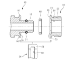
図1において、10,12は互いに接続すべき一対の管体で、一方の管体10は円筒形状の挿入軸部14を有している。
挿入軸部14は、外周側に断面円形且つ管軸方向に延びる平滑な雄嵌合面(嵌合部)16を有しており、その雄嵌合面16に対して、内周側に雌嵌合面(嵌合部)18を有するアダプタ20が嵌合されている。即ち一方の管体10に対して、これとは別体を成すアダプタ20が取り付けられている。
【0019】
アダプタ20は円筒形状をなしていて外周側に雄ねじ部22を有している。
このアダプタ20の雌嵌合面18と挿入軸部14の雄嵌合面16との間は、予め雄嵌合面16の環状溝に嵌込装着されたOリングから成る環状のシール部材24にて水密にシールされている。
【0020】
尚、アダプタ20の雌嵌合面18に環状溝を形成してそこにOリングから成る環状のシール部材24を装着し、そのシール部材24にて、アダプタ20の雌嵌合面18と挿入軸部14の雄嵌合面16との間を水密にシールすることもできる。
【0021】
或いはまた、アダプタ20の軸方向端の半径方向の当接面26と管体10側の半径方向の当接面30との間にシール部材を介在させて、それによりアダプタ20と管体10との間を水密にシールするようになすこともできる。
【0022】
管体10の当接面30には、管体10の軸心から半径方向に離れた位置において、係合凹部としてのキー溝28が周方向に180°隔たる2箇所に設けられている。
一方アダプタ20の当接面26には、対応する係合突部としてのキー32が、当接面26から管軸方向に突出する状態で設けられており、そのキー32がキー溝28に挿入されてそれらが互いに係合させられている。
【0023】
そしてこれらキー溝28とキー32との係合により、アダプタ20が管体10に対して回止めされている。
即ちこの例ではキー溝28とキー32とにより、アダプタ20の回止装置が構成されている。
【0024】
但し本例ではアダプタ20の当接面26にキー溝28と同様の形状の埋込凹部34が形成されていて、そこに図2に示しているように矩形ブロック状の小片が埋め込まれることでキー32が設けられている。
【0025】
従ってこの例の場合、埋込凹部34がキー溝であり、そこにキー32が挿入し係合しているものと考えることもできる。
即ち当接面26,30の何れにもキー溝が形成されて、キー32が管体10とアダプタ20とにまたがって各キー溝に挿入し、係合しているものと考えることができる。
【0026】
但しキー32を管体10側に一体的に形成し、これをアダプタ20に形成したキー溝に挿入係合させるようになすこともできるし、或いはまたアダプタ20に一体的に形成したキー32を、管体10側に形成したキー溝28に挿入し係合させることも可能である。
【0027】
上記挿入軸部14には、先端部近傍において外周側の雄嵌合面16に環状溝36が形成されていて、そこにCリング,Eリング等の半径方向に弾性を有する止め輪(スナップリング)38が嵌込装着されている。
一方アダプタ20の軸方向先端面は、半径方向のストッパ面39とされており、そこに止め輪38が当接させられ、以ってアダプタ20が一方の管体10から管軸方向に抜止めされている。
本例では、これら環状溝36,止め輪38,ストッパ面39によりアダプタ20の抜止装置が構成されている。
【0028】
尚、一方の管体10には半径方向外向きに突出する状態で鍔状部としての周方向に連続した環状のフランジ部40が設けられている。
尚、このフランジ部40に代えて、半径方向外向きに突出する鍔状部を周方向に不連続で且つ一定間隔で複数設けておいても良い。
【0029】
上記他方の管体12は、管本体42と、これに回転可能に装着された、内周側に雌ねじ部44を有する袋ナット46とを有している。
管本体42及び袋ナット46はそれぞれ半径方向外向きのフランジ部48及び半径方向内向きのフランジ部50を有しており、それらフランジ部48,50の当接によって、袋ナット46が管本体42から抜止めされている。
【0030】
本例の場合、一方の管体10が雄嵌合面16における嵌合接続方式であり、また他方の管体12が雌ねじ部44によるねじ接続方式であるにも拘らず、アダプタ20を一方の管体10と他方の管体12との間に介在させることによって、それら一対の管体10,12を支障なく接続することができる。
【0031】
具体的には、例えば一方の管体10にアダプタ20を取り付けておき、そのアダプタ20に対して他方の管体12の袋ナット46を雌ねじ部44においてねじ込むことで、一対の管体10,12を接続することができる。
【0032】
このとき、アダプタ20は管体10に対して回止めされているため、アダプタ20と袋ナット46とをねじ結合する際、アダプタ20が管体10に対して相対回転してしまうことがなく、従って管体10と管体12とを良好に接続作業することができる。
【0033】
尚その接続に際して、アダプタ20と他方の管体12とによりリング状のシール部材52を、アダプタ20の軸方向端面(ストッパ面39)と他方の管体12のフランジ部48とにより軸方向に挾み込むことで、両者を水密にシールすることができる。
【0034】
本例の場合、内周側に雌嵌合面18を有する他方の管体13に対しても一方の管体10を接続することができる。
具体的には、(B)に示しているようにアダプタ20を取り外した状態で一方の管体10の挿入軸部14を他方の管体13の内部に挿入し、そして一方の管体10の雄嵌合面16と他方の管体13の雌嵌合面18とを嵌合させた状態で、一対の管体10,13のフランジ部40,54をクランプ部材としての弾性クリップ56によりクランプすることで、一対の管体10,13を接続することができる。
【0035】
ここで弾性クリップ56は、帯状の金属板ばね材を略リング状に回曲変形させた形態をなしている。
詳しくは、この弾性クリップ56は周方向所定箇所に嵌込用開口58を有しており、また幅方向中間部において係入溝60が周方向に沿って形成されている。
【0036】
また嵌込用開口58と反対側には、上記フランジ部40,54との干渉を回避するための逃げ部62が形成されており、更に嵌込用開口58に続く部分には、ハの字状に開いたガイド部64が形成されている。
【0037】
かかる形態の弾性クリップ56を一対の管体10,13にまたがるように弾性的に嵌着し、そして一対の管体10,13におけるフランジ部40,54を、弾性クリップ56の係入溝60に係入させることで、かかる弾性クリップ56により一対の管体10,13を接続することができる。
【0038】
図3は本発明の他の実施例を示している。
同図に示しているように管体10の当接面30には六角形状の係合凹部66が形成されており、そこにリング状且つ外形形状が対応する六角形状をなす係合突部68が挿入されて係合させられるようになっている。
【0039】
ここで係合突部68は、アダプタ20の当接面36に形成された六角形状の埋込凹部70内部に、外形形状が六角形状のリング状の小片を埋め込むことでアダプタ20側に且つ当接面36から突出する状態に設けられている。
【0040】
そしてその係合突部68と係合凹部66との係合作用に基づいて、アダプタ20が管体10に対し回止めされている。
即ちこの例では、係合凹部66と係合突部68とによりアダプタ20の回止装置が構成されている。
尚係合凹部66,係合突部68,埋込凹部70は、それぞれその中心が管体10及びアダプタ20の軸心と一致させられている。
【0041】
尚この例においても、係合凹部66が埋込凹部であってそこに係合突部68を構成すべきリング状小片が埋め込まれて係合突部68とされる一方、アダプタ20側の埋込凹部70が係合凹部であって、そこに係合突部68が挿入し係合しているものと考えることもできる。
【0042】
本実施例においても、また、上記第一の実施例と同様にアダプタ20側に係合突部68を一体的に設けて、これを管体10側に形成した対応する形状の係合凹部66に係合させることもできるし、或いは逆に管体10側に係合突部68を一体的に設けて、これをアダプタ20側に形成した対応する形状の係合凹部に係合させるといったことも可能である。
この場合においても回止装置を簡単な構造で構成することができる。
【0043】
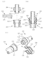
図4は本発明の他の実施例を示したものである。
この例は、アダプタ20にフランジ部72を設け、そのフランジ部72と一方の管体10のフランジ部40及びクランプ部材としての弾性クリップ56によって抜止手段を構成したものである。
【0044】
この例の場合、一方の管体10とアダプタ20の各フランジ部40,72を当接させた状態において、それらにまたがるように弾性クリップ56を嵌着し、そしてフランジ部40,72を弾性クリップ56の係入溝60内部に係入させることで、アダプタ20を管体10に取り付け、抜止めすることができる。
【0045】
尚、本例においてもアダプタ20と管体10とにまたがって回止装置が設けられている。
その回止装置の構成は図3に示す実施例と同様である。但しその回止装置を図1及び図2に示す実施例と同様の構成とすることも勿論可能である。
【0046】
この例では、アダプタ20を予め他方の管体12の袋ナット46、つまりその内周側の雌ねじ部44にねじ込んでおき、その状態で一方の管体10と他方の管体12とをアダプタ20を介して接続するといったことも可能である。
【0047】
図5に示しているようにこの場合においてアダプタ20と袋ナット46とをねじ結合する際、係合突部68を工具係合部として利用し、それらをねじ結合することができる。
或いはまた、係合突部68を構成する小片を取り外した状態において六角形状の埋込凹部70を工具係合部として利用することもできる。
尚この埋込凹部70は、係合凹部として考えることもできる点は前述した通りである。
【0048】
本実施例においても、回止装置を図1及び図2に示す実施例と同様の構成で設けることができ、この場合においてキー32ないし埋込凹部34を工具係合用の部分として利用することができる。
【0049】
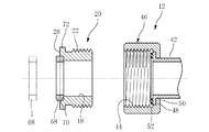
図6は参考例を示している。
同図において74はアダプタで、この例のアダプタ74は、軸方向一端側にフランジ部54と雌嵌合面18とを有し、また軸方向他端側に雌ねじ部44を有している。
また軸方向中間部において半径方向内向きに突出するフランジ部76を有している。
78は他方の管体で、軸端部外周側に雄ねじ部80を有している。
【0050】
本例においてもアダプタ74と一方の管体10とにまたがって回止装置が設けられている。
その回止装置の構成は図3に示すものと同様である。但し図1及び図2に示すものと同様の構成で回止装置を設けることもできる。
【0051】
この例の場合、管体10の雄嵌合面16とアダプタ74の雌嵌合面18とを互いに嵌合させるとともに、弾性クリップ56にてそれらを結合しておき、即ちアダプタ74を管体10に取り付けておき、そしてそのアダプタ74の雌ねじ部44と他方の管体78の雄ねじ部80とをねじ結合することで、一対の管体10及び78を互いに接続状態とすることができる。
【0052】
その接続作業の際、具体的にはアダプタ74の雌ねじ部44と管体78の雄ねじ部80とをねじ結合する際、アダプタ74が回止装置によって管体10に対し相対回転するのが防止されているため、管体10及び78を良好に接続作業することができる。
【0053】
尚、アダプタ74を予め他方の管体78にねじ結合しておき、その状態でアダプタ74を介し管体10と78とを接続するといったことも可能である。
この場合においても嵌合突部68ないし埋込凹部70、或いはキー32ないし埋込凹部34を工具の係合部として利用することができ、アダプタ74と管体78とを容易にねじ結合することができる。
尚、アダプタ74の外周部に工具係合部82を設けておいて、その工具係合部82に工具を係合させることで、アダプタ74と管体78とをねじ結合することもできる。
【0054】
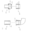
図7は他の参考例を示している。
同図(A)において、一方の管体10には雌嵌合面18が形成されている。
一方アダプタ84には、管軸方向一端側に短い筒状の挿入軸部86が設けられており、その外周側には雄嵌合面16が形成されている。
またアダプタ84の軸方向他端側の外周側には雄ねじ部80が形成されている。
【0055】
この例の場合、アダプタ84を管体10に取り付けることによって、管体10側に雄ねじ部80を具備させることができる。
従って他方の管体が雌ねじ部を有するものである場合、そのアダプタ84の雄ねじ部80を用いて他方の管体とねじ接続することができる。
【0056】
尚、この例においてもアダプタ84と管体10とにまたがって回止装置が設けられている。
その回止装置の構成は図3に示す実施例のものと同様である。但し図1及び図2に示す実施例の回止装置と同様の構成で回止装置を設けることもできる。
【0057】
本例の場合、管体10のフランジ部40とアダプタ84のフランジ部54及び図1の弾性クリップ56を用いて管体10とアダプタ84とを抜止めすることができる。
即ちそれらによってアダプタ84を管体10に組み付けることができる。
【0058】
図7(B)は更に他の参考例を示したものである。
この例では、アダプタ88として軸方向一端側に雌ねじ部44を有するものを用いている。
他の点については図7(A)に示すものと同様である。
【0059】
この例の場合、アダプタ88を管体10に組み付けることによって、管体10側に雌ねじ部44を具備させることができる。
従って他方の管体が雄ねじ部を有するものである場合、かかるアダプタ88を用いることによって、管体10と他方の管体とを良好に接続することができる。
【0060】
尚、この図7(B)に示す例においても、アダプタ88と管体10とにまたがって図3に示すのと同様の回止装置、或いは図1及び図2に示すのと同様の回止装置を設けておくことができる。
【0061】
以上本発明の実施例を参考例とともに詳述したがこれはあくまで一例示である。
例えば本発明においては、上記六角形状の係合突部68及び対応する係合凹部66,埋込凹部70の形状を六角形状以外の多角形状ないしその他の非円形形状となすことも可能であるし、またアダプタの形態を他の形態とすること、更にアダプタと一方の管体との組合せを上例以外の他の組合せとなし、その場合においてアダプタと一方の管体とにまたがって回止装置を設けることも可能であるなど、本発明はその主旨を逸脱しない範囲において種々変更を加えた形態で構成可能である。
【図面の簡単な説明】
【図1】 本発明の一実施例を示す図である。
【図2】 図1における一方の管体とアダプタとを分解して示す斜視図である。
【図3】 本発明の他の実施例を示す図である。
【図4】 本発明の更に他の実施例を示す図である。
【図5】 図4の実施例における一組付手順を示す図である。
【図6】 参考例の図である。
【図7】 他の参考例の図である。
【図8】 従来の管体接続構造の一例を示す図である。
【図9】 従来の管体接続構造の、図8とは異なる例を示す図である。
【符号の説明】
10,12,78 管体
16 雄嵌合面(嵌合部)
18 雌嵌合面(嵌合部)
20,74,84,88 アダプタ
22,80 雄ねじ部
26,30 当接面
28 キー溝(係合凹部)
32 キー(係合突部)
34,70 埋込凹部
40,54 フランジ部
44 雌ねじ部
56 弾性クリップ
66 係合凹部
68 係合突部[0001]
BACKGROUND OF THE INVENTION
The present invention relates to a tube connecting method, and more particularly to a tube connecting method using an adapter.
[0002]
[Prior art]
Conventionally, as a tube connection structure for connecting a pair of tubes, for example, a tube connection structure for connecting a faucet fitting and a pipe, a tube connection structure as shown in FIG. 8 is generally used. Yes.
In the figure,
[0003]
206 is the other pipe body (for example, on the faucet side), and a cap nut 212 (FIG. (B)) having a male screw portion 208 (FIG. (A)) on the outer peripheral side of the tip portion or a
[0004]
In the case of this conventional connection structure, as shown in (A), the male threaded
[0005]
The seal between the pair of
[0006]
However, in the case of the connection structure of FIG. 8, the construction is complicated, such as winding the seal tape or screwing the threaded portion with a tool, and it is necessary to rotate it several times. There is a problem that variations in construction occur due to winding or screwing.
[0007]
In contrast, a connection structure as shown in FIG. 9 has recently been used.
In this connection structure, a pair of tubular bodies can be connected with one touch using a clamp member.
More specifically, in the figure,
[0008]
220 is a female fitting surface having a smooth circular cross section provided in the
[0009]
The
[0010]
In the case of this connection structure, the
[0011]
In the case of this connection structure, the
Alternatively, a
Alternatively, a seal member can be sandwiched between the
[0012]
The connection structure shown in FIG. 8 can be used to connect the
[0013]
[Problems to be solved by the invention]
However, at present, the present situation is that the screw connection method shown in FIG. 8 and the fitting connection method of the fitting portion (male fitting surface, female fitting surface) shown in FIG. 9 coexist. When trying to connect a pair of tubes at the site, one tube is of the screw connection method shown in FIG. 8, and the other tube is of the fitting connection method shown in FIG. Can occur.
Alternatively, it may occur that one tube body and the other tube body have different connection methods other than those exemplified above.
In this case, both pipes cannot be connected as they are, and therefore it may happen that the pipe connection construction must be interrupted.
[0014]
[Means for Solving the Problems]
The invention of the present application has been made to solve such problems.
Thus, the pipe connection method according to claim 1 is a pipe connection method for connecting a pair of pipes, and a fitting connection method having a fitting surface and an annular flange portion protruding radially outward. When connecting one tube body of this to the other tube body of the screw connection system, an adapter having a male thread portion corresponding to the thread portion of the other tube body is provided over the entire length of the adapter in the tube axis direction. The one tubular body is attached to the fitting surface of the one tubular body, and the one tubular body and the other tubular body are connected via the adapter, and each of them is a fitting connection system. When connecting one tubular body and the other tubular body, the one tubular body and the other tubular body are fitted to each other with the adapter removed from the one tubular body, and the one tubular body Clamp each flange with the other tube , Characterized by connecting the pair of the tube.
[0015]
The tube connection method according to claim 2 is the tube connection method according to claim 1, wherein the adapter is provided with an annular flange portion protruding radially outward, and the flange portion of the one tube body is provided. The flange portion of the adapter is clamped by a clamp member, and the adapter is attached to the one pipe body.
[0016]
[Operation and effect of the invention]
As described above, the pipe connection method of the present invention is such that a pair of pipes are connected via an adapter. In this pipe connection method, the pair of pipes are different from each other. Even in this case, a pair of tubular bodies can be satisfactorily connected by using an adapter corresponding to this.
[0017]
In this tubular body connection method, the fitting portion of the adapter is attached to the tubular body so as to be fitted to the corresponding fitting portion of the tubular body on the adapter attachment side .
[0018]
【Example】
Next, embodiments of the present invention will be described in detail with reference to the drawings.
In FIG. 1,
The
[0019]
The
Between the female
[0020]
An annular groove is formed in the female
[0021]
Alternatively, a seal member is interposed between the
[0022]
On the
On the other hand, a key 32 as a corresponding engagement protrusion is provided on the
[0023]
The
That is, in this example, the
[0024]
However, in this example, an embedded
[0025]
Therefore, in this example, it can be considered that the embedded
That is, it can be considered that a key groove is formed on both of the contact surfaces 26 and 30, and the key 32 is inserted into and engaged with each key groove across the
[0026]
However, the key 32 can be formed integrally with the
[0027]
An
On the other hand, the distal end surface in the axial direction of the
In this example, the
[0028]
One
Instead of the
[0029]
The
Each of the tube
[0030]
In the case of this example, the
[0031]
Specifically, for example, the
[0032]
At this time, since the
[0033]
In this connection, the ring-shaped
[0034]
In the case of this example, one
Specifically, as shown in (B), with the
[0035]
Here, the
Specifically, the
[0036]
Further, an
[0037]
The
[0038]
FIG. 3 shows another embodiment of the present invention.
As shown in the figure, a
[0039]
Here, the
[0040]
Based on the engaging action between the engaging
In other words, in this example, the engaging
Note that the centers of the engaging
[0041]
In this example as well, the engaging
[0042]
Also in this embodiment, similarly to the first embodiment, an engaging
Even in this case, the rotation stopping device can be configured with a simple structure.
[0043]
FIG. 4 shows another embodiment of the present invention.
In this example, the
[0044]
In the case of this example, in a state where the one
[0045]
In this example as well, a rotation stop device is provided across the
The structure of the rotation stop device is the same as that of the embodiment shown in FIG. However, it is of course possible to have the same structure as that of the embodiment shown in FIGS.
[0046]
In this example, the
[0047]
As shown in FIG. 5, in this case, when the
Alternatively, the hexagonal embedded
The embedded
[0048]
Also in this embodiment, the rotation stop device can be provided in the same configuration as the embodiment shown in FIGS. 1 and 2, and in this case, the key 32 or the embedded
[0049]
FIG. 6 shows a reference example .
In the drawing,
Moreover, it has the
[0050]
Also in this example, a rotation stop device is provided across the
The structure of the stopping device is the same as that shown in FIG. However, it is also possible to provide a stop device with the same configuration as that shown in FIGS.
[0051]
In the case of this example, the
[0052]
During the connection work, specifically, when the
[0053]
It is also possible to connect the
Even in this case, the
In addition, the
[0054]
FIG. 7 shows another reference example .
In FIG. 2A, a female
On the other hand, the
A
[0055]
In the case of this example, by attaching the
Therefore, when the other tube body has a female threaded portion, it can be screw-connected to the other tube body using the male threaded
[0056]
In this example as well, a rotation stop device is provided across the
The structure of the stopping device is the same as that of the embodiment shown in FIG. However, it is also possible to provide a stop device with the same configuration as the stop device of the embodiment shown in FIGS.
[0057]
In the case of this example, the
That is, the
[0058]
FIG. 7B shows another reference example .
In this example, an
Other points are the same as those shown in FIG.
[0059]
In the case of this example, by assembling the
Therefore, when the other tube body has a male thread portion, the
[0060]
In the example shown in FIG. 7B as well, the same stopping device as shown in FIG. 3 across the
[0061]
Although the embodiment of the present invention has been described in detail with reference examples, this is merely an example.
For example, in the present invention, the
[Brief description of the drawings]
FIG. 1 is a diagram showing an embodiment of the present invention.
2 is an exploded perspective view showing one tube body and an adapter in FIG. 1; FIG.
FIG. 3 is a diagram showing another embodiment of the present invention.
FIG. 4 is a diagram showing still another embodiment of the present invention.
FIG. 5 is a diagram showing an assembling procedure in the embodiment of FIG. 4;
FIG. 6 is a diagram of a reference example .
FIG. 7 is a diagram of another reference example .
FIG. 8 is a diagram showing an example of a conventional tube connection structure.
FIG. 9 is a view showing an example different from FIG. 8 of a conventional tube connection structure.
[Explanation of symbols]
10, 12, 78
18 Female mating surface (fitting part)
20, 74, 84, 88
32 keys (engagement protrusion)
34, 70 Embedded
Claims (2)
またそれぞれ嵌合接続方式である前記一方の管体と他方の管体とを接続するに際して、前記アダプタを前記一方の管体から取り外した状態でそれら一方の管体と他方の管体とを互いに嵌合させ、それら一方の管体と他方の管体との各フランジ部をクランプ部材にてクランプすることで、それら一対の管体を接続することを特徴とする管体接続方法。A pipe connection method for connecting a pair of pipe bodies, one pipe body of a fitting connection method having a fitting surface and an annular flange portion projecting radially outward, and the other of the screw connection method When connecting a pipe body, an adapter having a male thread part corresponding to the thread part of the other pipe body is fitted to the fitting surface of the one pipe body over the entire length in the pipe axis direction of the adapter. Attached to the state, so as to connect the one tube body and the other tube body through the adapter,
Further, when connecting the one tube body and the other tube body, which are respectively fitted and connected, the one tube body and the other tube body are connected to each other with the adapter removed from the one tube body. A pipe connecting method characterized in that the pair of pipes are connected by fitting and clamping each flange part of the one pipe and the other pipe with a clamp member.
Priority Applications (1)
| Application Number | Priority Date | Filing Date | Title |
|---|---|---|---|
| JP23200098A JP4066397B2 (en) | 1998-08-18 | 1998-08-18 | Tube connection method |
Applications Claiming Priority (1)
| Application Number | Priority Date | Filing Date | Title |
|---|---|---|---|
| JP23200098A JP4066397B2 (en) | 1998-08-18 | 1998-08-18 | Tube connection method |
Publications (2)
| Publication Number | Publication Date |
|---|---|
| JP2000065260A JP2000065260A (en) | 2000-03-03 |
| JP4066397B2 true JP4066397B2 (en) | 2008-03-26 |
Family
ID=16932378
Family Applications (1)
| Application Number | Title | Priority Date | Filing Date |
|---|---|---|---|
| JP23200098A Expired - Fee Related JP4066397B2 (en) | 1998-08-18 | 1998-08-18 | Tube connection method |
Country Status (1)
| Country | Link |
|---|---|
| JP (1) | JP4066397B2 (en) |
Families Citing this family (7)
| Publication number | Priority date | Publication date | Assignee | Title |
|---|---|---|---|---|
| JP4793699B2 (en) * | 2004-10-13 | 2011-10-12 | イートン コーポレーション | Low pressure connection bracket |
| US7182312B1 (en) * | 2005-10-26 | 2007-02-27 | Harsco Technologies Corporation | Replaceable outlet on a cylinder valve |
| JP2008051168A (en) * | 2006-08-23 | 2008-03-06 | Nok Corp | Sealing device |
| JP5072471B2 (en) * | 2007-07-30 | 2012-11-14 | 株式会社川西水道機器 | Pipe detachment prevention device for union nut joint |
| KR101274062B1 (en) | 2011-10-06 | 2013-06-12 | 박정식 | advanced structure of hose-coupling apparatus for water valve |
| CN106499717B (en) * | 2016-12-21 | 2019-03-12 | 申益 | A kind of nut collar fixed connection structure |
| JP7340506B2 (en) | 2020-10-16 | 2023-09-07 | 因幡電機産業株式会社 | drainage fittings |
-
1998
- 1998-08-18 JP JP23200098A patent/JP4066397B2/en not_active Expired - Fee Related
Also Published As
| Publication number | Publication date |
|---|---|
| JP2000065260A (en) | 2000-03-03 |
Similar Documents
| Publication | Publication Date | Title |
|---|---|---|
| KR930006017B1 (en) | Liquid tight connector for flexible non-metallic conduit and flexible non-metallic tubing | |
| US5048875A (en) | Connector interposed between small-diameter metallic pipe and flexible hose | |
| JPH0343516B2 (en) | ||
| KR20050062560A (en) | Connector device for pipes | |
| JPH0158396B2 (en) | ||
| JP4066397B2 (en) | Tube connection method | |
| EP0200339B1 (en) | Pipe couplings | |
| JPH04296291A (en) | Pipe joint | |
| JP2000088157A (en) | Pipe body connection structure | |
| JP4034433B2 (en) | Tube connection structure | |
| JP2000074274A (en) | Pipe body connecting structure | |
| JP3778701B2 (en) | Tube connection structure | |
| JP3808870B2 (en) | Tube connection structure | |
| JP3932509B2 (en) | Pipe fitting | |
| JP2000088163A (en) | Pipe body connection structure | |
| JP2935718B2 (en) | Arrangement connection structure of small diameter metal tube and flexible hose | |
| JP4245127B2 (en) | Connection structure between water pipe and connector | |
| JP2536369Y2 (en) | Corrugated pipe insertion type pipe fitting | |
| JP2002013683A (en) | Pipe fitting | |
| JP2004360713A (en) | Gas cock | |
| JP4514053B2 (en) | Header and header water stop method | |
| JP2004100720A (en) | Pipe fittings | |
| JP3370890B2 (en) | Pipe connection structure | |
| JPH0342304Y2 (en) | ||
| JPH0710155Y2 (en) | Coupling device for piping |
Legal Events
| Date | Code | Title | Description |
|---|---|---|---|
| A621 | Written request for application examination |
Free format text: JAPANESE INTERMEDIATE CODE: A621 Effective date: 20040318 |
|
| A977 | Report on retrieval |
Free format text: JAPANESE INTERMEDIATE CODE: A971007 Effective date: 20051115 |
|
| A131 | Notification of reasons for refusal |
Free format text: JAPANESE INTERMEDIATE CODE: A131 Effective date: 20060117 |
|
| A521 | Written amendment |
Free format text: JAPANESE INTERMEDIATE CODE: A523 Effective date: 20060318 |
|
| A02 | Decision of refusal |
Free format text: JAPANESE INTERMEDIATE CODE: A02 Effective date: 20060509 |
|
| A521 | Written amendment |
Free format text: JAPANESE INTERMEDIATE CODE: A523 Effective date: 20060706 |
|
| A911 | Transfer of reconsideration by examiner before appeal (zenchi) |
Free format text: JAPANESE INTERMEDIATE CODE: A911 Effective date: 20060713 |
|
| A912 | Removal of reconsideration by examiner before appeal (zenchi) |
Free format text: JAPANESE INTERMEDIATE CODE: A912 Effective date: 20060811 |
|
| A521 | Written amendment |
Free format text: JAPANESE INTERMEDIATE CODE: A523 Effective date: 20071116 |
|
| A61 | First payment of annual fees (during grant procedure) |
Free format text: JAPANESE INTERMEDIATE CODE: A61 Effective date: 20071228 |
|
| FPAY | Renewal fee payment (event date is renewal date of database) |
Free format text: PAYMENT UNTIL: 20110118 Year of fee payment: 3 |
|
| R150 | Certificate of patent or registration of utility model |
Free format text: JAPANESE INTERMEDIATE CODE: R150 |
|
| FPAY | Renewal fee payment (event date is renewal date of database) |
Free format text: PAYMENT UNTIL: 20120118 Year of fee payment: 4 |
|
| S111 | Request for change of ownership or part of ownership |
Free format text: JAPANESE INTERMEDIATE CODE: R313111 |
|
| FPAY | Renewal fee payment (event date is renewal date of database) |
Free format text: PAYMENT UNTIL: 20120118 Year of fee payment: 4 |
|
| R350 | Written notification of registration of transfer |
Free format text: JAPANESE INTERMEDIATE CODE: R350 |
|
| FPAY | Renewal fee payment (event date is renewal date of database) |
Free format text: PAYMENT UNTIL: 20130118 Year of fee payment: 5 |
|
| FPAY | Renewal fee payment (event date is renewal date of database) |
Free format text: PAYMENT UNTIL: 20140118 Year of fee payment: 6 |
|
| LAPS | Cancellation because of no payment of annual fees |