JP4052386B2 - Tire mold and method of manufacturing pneumatic tire using the same - Google Patents
Tire mold and method of manufacturing pneumatic tire using the same Download PDFInfo
- Publication number
- JP4052386B2 JP4052386B2 JP2003046730A JP2003046730A JP4052386B2 JP 4052386 B2 JP4052386 B2 JP 4052386B2 JP 2003046730 A JP2003046730 A JP 2003046730A JP 2003046730 A JP2003046730 A JP 2003046730A JP 4052386 B2 JP4052386 B2 JP 4052386B2
- Authority
- JP
- Japan
- Prior art keywords
- sipe
- forming blade
- tire
- reinforcing portion
- sipe forming
- Prior art date
- Legal status (The legal status is an assumption and is not a legal conclusion. Google has not performed a legal analysis and makes no representation as to the accuracy of the status listed.)
- Expired - Fee Related
Links
Images


Description
【0001】
【発明の属する技術分野】
本発明は、タイヤ金型及びそれを用いた空気入りタイヤの製造方法に関し、更に詳しくは、セクター分割位置まで延在するサイプ成形刃の変形を抑制するようにしたセクショナル型のタイヤ金型及びそれを用いた空気入りタイヤの製造方法に関する。
【0002】
【従来の技術】
一般に、セクショナル型のタイヤ金型は、上下の金型間に側型を複数に分割したセクターを備えている。ブロックやリブなどの陸部にサイプを設けたタイヤを製造するのに用いられるセクショナル型のタイヤ金型では、セクターの成形面にサイプ成形刃が突設されており、トレッドパターンのデザイン上、1本のサイプ成形刃がセクター分割位置まで延在し、更に隣のセクターに跨って延びることがしばしばある。
【0003】
このようにセクター分割位置まで延在するサイプ成形刃を有するタイヤ金型でタイヤを製造すると、サイプ成形刃は非常に薄肉のため加硫後に金型を離型した際に変形することがあり、その都度修正しなければならない。
【0004】
そこで、従来、上記対策として、例えば、セクター分割位置にかかるサイプ成形刃の高さを低くして変形し難くするようにした技術が提案されている(例えば、特許文献1参照)。
【0005】
【特許文献1】
特許第3004776号
【0006】
【発明が解決しようとする課題】
しかしながら、上記のようにサイプ成形刃の高さを低くすると、トレッド面の陸部に形成されたサイプの深さが他のサイプより浅くなるため、本来あるべきサイプ特性を維持することができなくなるという問題があった。また、トレッド面が早期に摩耗した(摩耗により浅いサイプがなくなった)際にトレッドパターンの外観が著しく変わってしまうという問題もある。
【0007】
本発明の目的は、良好なサイプ特性を維持し、かつ摩耗によるトレッドパターンの外観変化を招くことなく、サイプ成形刃の変形を抑制することが可能なタイヤ金型及びそれを用いた空気入りタイヤの製造方法を提供することにある。
【0008】
【課題を解決するための手段】
上記目的を達成する本発明のタイヤ金型は、複数に分割したセクターの成形面にセクター分割位置まで延在するサイプ成形刃を直接設けたセクショナル型のタイヤ金型において、前記サイプ成形刃の一方の側面にのみ前記セクター分割位置に隣接して金属板からなる補強部を設け、該補強部は、セクター分割位置からサイプ成形刃の幅方向に延びる一方、セクターの成形面からサイプ成形刃の高さ方向に延び、かつ厚さが前記サイプ成形刃の厚さ以下であることを特徴とする。
【0009】
本発明の空気入りタイヤの製造方法は、上記タイヤ金型を用いて空気入りタイヤを製造することを特徴とする。
【0010】
上記した本発明によれば、セクター分割位置に隣接するサイプ成形刃の側面に設けた補強部によりサイプ成形刃を効果的に補強することができるため、サイプ成形刃の高さを低くすることなく、金型離型時のサイプ成形刃の変形を抑制することができる。
【0011】
【発明の実施の形態】
以下、本発明の構成について添付の図面を参照しながら詳細に説明する。
【0012】
図1は、本発明のタイヤ金型の一例を示し、このセクショナル型のタイヤ金型は、環状の上下の金型1,2と、その間に配置した環状の側型3を有し、側型3が複数に分割したセクター4から構成されている。
【0013】
上型1は、タイヤの一方のサイド部を成形する成形面1aを下面に有している。下型2は、タイヤの他方のサイド部を成形する成形面2aを上面に備えている。上型1及び下型2の内周側にはタイヤのビード部を成形する上下のビードリングB1,B2が設けられている。各セクター4は、タイヤのトレッド部を成形する成形面4aを内周面に有している。
【0014】
セクター4の成形面4aには、トレッド面に周方向溝を成形する複数の溝成形刃5が側型3の周方向に沿って突設され、この溝成形刃5間の成形面4aには複数のサイプ成形刃6が直接突出して設けられている。サイプ成形刃6は、同じ高さで溝成形刃5間に斜めに延在し、その一部のサイプ成形刃6Xが図2に示すように、セクター分割位置Xまで延在し、隣接するセクター4のサイプ成形刃6Xと共同して1本のサイプを成形するようになっている。
【0015】
各サイプ成形刃6Xの一方の側面にのみ、セクター分割位置Xに隣接して金属板Pからなる補強部7が固設されている。補強部7は、セクター分割位置Xからサイプ成形刃6Xの幅方向に延び、かつ成形面4aからサイプ成形刃6Xの高さ方向に延在するように設けられている。
【0016】
このようにサイプ成形刃6Xの側面にセクター分割位置Xに隣接して金属板Pからなる補強部7を設けてサイプ成形刃6Xを補強することにより、サイプ成形刃の高さを低くすることなく、金型離型時のサイプ成形刃6Xの変形を抑制することができる。従って、本来あるべきサイプ特性を損なうことなく、また摩耗によるトレッドパターンの外観変化を招くことなく、サイプ成形刃6Xの変形抑制が可能になる。
【0017】
本発明において、上記補強部7の高さhとしては、成形面4aからサイプ成形刃6Xの高さHの1/4〜1/2倍の位置となるようにするのがよい。補強部7の高さhがサイプ成形刃6Xの高さHの1/4倍より低いと、効果的な補強を得ることが難しく、逆に1/2倍を超えると、サイプ特性の低下を招く。
【0018】
サイプ成形刃6Xが延在する方向に沿った補強部7の長さmとしては、セクター分割位置Xからサイプ成形刃6Xの長さMの1/4〜1/2倍の長さとなるようにするのがよい。補強部7の長さmがサイプ成形刃6Xの長さMの1/4倍より短いと、良好な補強効果を得ることが難しく、逆に1/2倍を超えると、サイプ特性上好ましくない。なお、この補強部7の長さm及びサイプ成形刃6Xの長さMは、図示するように厚さ方向の中心を通る中心線O,O’上で測定した長さである。
【0019】
補強部7の厚さtとしては、サイプ特性の観点からサイプ成形刃6Xの厚さT以下とする。下限値としては、補強部7の材質により様々な値を取ることができるが、サイプ成形刃と同じ材質、即ちサイプ成形刃は一般にステンレス鋼で形成されているが、その場合にはサイプ成形刃6Xの厚さTの1/2倍以上にするのが補強効果の点から好ましい。
【0020】
上述した補強部7は、金属板Pに代えて,図3に示すように、サイプ成形刃6Xの一方の側面にのみサイプ成形刃6Xと同じ材料で一体的に板状に厚肉成形した厚肉部10から構成するようにしてもよい。
【0021】
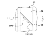
図4に上述したタイヤ金型を使用して製造した空気入りタイヤの要部を示す。トレッド面21にタイヤ周方向Cに沿って延在する複数の周方向溝22が設けられ、この周方向溝22間に形成された陸部24に複数のサイプ23が形成されている。サイプ23は、周方向溝22に連通し、セクター分割位置Xに跨ったサイプ23Xは、その位置に対応するサイプ23Xの中間部に幅広部23Xaが形成された構成になっている。
【0022】
このようなサイプ23Xを有する空気入りタイヤは、上記タイヤ金型をタイヤ加硫機に取り付け、従来と同様にして、グリーンタイヤをタイヤ金型内にセットした後、加圧加熱して加硫することにより得ることができる。
【0023】
本発明は、上記実施形態では、直線状に延在するサイプ成形刃6を有するタイヤ金型の例について説明したが、そのサイプ成形刃の形状はジグザグ状や、曲線状に延在するものであってもよく、またサイプ成形刃6は上述したように溝成形刃5間にわたって延在するものに限定されず、セクター分割位置Xまで延在するサイプ成形刃を有するセクショナル型のタイヤ金型であればいずれにも適用することができる。
【0024】
また、上述した補強部7は、サイプ成形刃6Xの一方の側面にのみセクター分割位置Xに隣接して配置されるが、補強部7の長さmがサイプ成形刃6Xの長さMの1/2倍未満である場合には、補強部7から離間したサイプ成形刃6Xの一方の側面に同様の補助補強部を設けるようにしてもよい。その場合、補助補強部の長さは、補強部7の長さmとの合計の長さがサイプ成形刃6Xの長さMの1/2倍を超えないものとする。
【0025】
【発明の効果】
上述したように本発明は、複数に分割したセクターの成形面にセクター分割位置まで延在するサイプ成形刃を備えたセクショナル型のタイヤ金型において、サイプ成形刃の側面にセクター分割位置に隣接して板状の補強部を設けたので、良好なサイプ特性を維持し、かつ摩耗によるトレッドパターンの外観変化を招くことなく、サイプ成形刃の変形を抑制することができる。
【図面の簡単な説明】
【図1】本発明のタイヤ金型の一例を示す要部縦断面図である。
【図2】セクターの要部拡大図を示し、(a)は環状の側型の内周側からみた拡大図、(b)は(a)の矢視方向から見た拡大図である。
【図3】本発明のタイヤ金型に使用されるセクターの他の例を、補強部を含むサイプ成形刃を横断する断面で示す要部拡大断面図である。
【図4】図1のタイヤ金型を用いて製造した空気入りタイヤの一例を示す要部拡大平面図である。
【符号の説明】
1 上型 2 下型
3 側型 4 セクター
4a 成形面 6,6X サイプ成形刃
7 補強部 10 肉厚部
H サイプ成形刃の高さ M サイプ成形刃の長さ
P 金属板 T サイプ成形刃の厚さ
X セクター分割位置 h 補強部の高さ
m 補強部の長さ t 補強部の厚さ[0001]
BACKGROUND OF THE INVENTION
The present invention relates to a tire mold and a method of manufacturing a pneumatic tire using the same, and more specifically, a sectional type tire mold that suppresses deformation of a sipe molding blade that extends to a sector division position and the same. The present invention relates to a method for manufacturing a pneumatic tire using a rubber.
[0002]
[Prior art]
Generally, a sectional type tire mold includes a sector in which a side mold is divided into a plurality of parts between upper and lower molds. In a sectional type tire mold used to manufacture tires with sipes on land such as blocks and ribs, a sipe molding blade is projected on the molding surface of the sector. Often, a sipe forming blade of a book extends to a sector division position and further extends to adjacent sectors.
[0003]
Thus, when a tire is manufactured with a tire mold having a sipe molding blade extending to the sector division position, the sipe molding blade may be deformed when the mold is released after vulcanization because it is very thin, It must be corrected each time.
[0004]
Therefore, conventionally, as a countermeasure, for example, a technique has been proposed in which the height of the sipe forming blade at the sector division position is lowered to make it difficult to deform (for example, see Patent Document 1).
[0005]
[Patent Document 1]
Japanese Patent No. 3004776 [0006]
[Problems to be solved by the invention]
However, if the height of the sipe forming blade is lowered as described above, the sipe depth formed in the land portion of the tread surface becomes shallower than other sipe, so that the sipe characteristics that should be originally cannot be maintained. There was a problem. There is also a problem that the appearance of the tread pattern changes remarkably when the tread surface is worn early (the shallow sipe is lost due to wear).
[0007]
An object of the present invention is to provide a tire mold capable of maintaining good sipe characteristics and suppressing deformation of a sipe forming blade without causing an appearance change of a tread pattern due to wear, and a pneumatic tire using the same It is in providing the manufacturing method of.
[0008]
[Means for Solving the Problems]
The tire mold of the present invention that achieves the above object is a sectional type tire mold in which a sipe molding blade that extends to a sector division position is directly provided on a molding surface of a plurality of divided sectors, and one of the sipe molding blades A reinforcing portion made of a metal plate is provided only on the side surface of the sipe forming blade adjacent to the sector dividing position, and the reinforcing portion extends in the width direction of the sipe forming blade from the sector dividing position, while the height of the sipe forming blade extends from the molding surface of the sector. It extends in the vertical direction and has a thickness equal to or less than the thickness of the sipe forming blade .
[0009]
The pneumatic tire manufacturing method of the present invention is characterized by manufacturing a pneumatic tire using the tire mold.
[0010]
According to the above-described present invention, the sipe forming blade can be effectively reinforced by the reinforcing portion provided on the side surface of the sipe forming blade adjacent to the sector division position, so that the height of the sipe forming blade is not lowered. The deformation of the sipe molding blade at the time of mold release can be suppressed.
[0011]
DETAILED DESCRIPTION OF THE INVENTION
Hereinafter, the configuration of the present invention will be described in detail with reference to the accompanying drawings.
[0012]
FIG. 1 shows an example of a tire mold according to the present invention. This sectional type tire mold has annular upper and lower molds 1 and 2 and an annular side mold 3 disposed therebetween, and the side mold 3 is composed of
[0013]
The upper mold 1 has a molding surface 1a for molding one side portion of the tire on the lower surface. The lower mold 2 includes a
[0014]
On the
[0015]
A reinforcing
[0016]
In this way, by providing the reinforcing
[0017]
In the present invention, the height h of the reinforcing
[0018]
The length m of the reinforcing
[0019]
The thickness t of the reinforcing
[0020]
As shown in FIG. 3, the reinforcing
[0021]
The principal part of the pneumatic tire manufactured using the tire metal mold | die mentioned above in FIG. 4 is shown. A plurality of
[0022]
In a pneumatic tire having such a
[0023]
In the above-described embodiment, the present invention has been described with respect to an example of a tire mold having a
[0024]
The reinforcing
[0025]
【The invention's effect】
As described above, the present invention provides a sectional type tire mold having a sipe forming blade extending to a sector dividing position on a molding surface of a plurality of divided sectors, and adjacent to the sector dividing position on the side surface of the sipe forming blade. Since the plate-shaped reinforcing portion is provided, the deformation of the sipe forming blade can be suppressed without damaging the appearance of the tread pattern due to wear while maintaining good sipe characteristics.
[Brief description of the drawings]
FIG. 1 is a longitudinal sectional view of an essential part showing an example of a tire mold of the present invention.
2A and 2B are enlarged views of essential parts of the sector, in which FIG. 2A is an enlarged view seen from the inner peripheral side of the annular side mold, and FIG. 2B is an enlarged view seen from the arrow direction of FIG.
FIG. 3 is an enlarged cross-sectional view of a main part showing another example of a sector used in the tire mold of the present invention in a cross section crossing a sipe forming blade including a reinforcing part.
4 is an enlarged plan view of an essential part showing an example of a pneumatic tire manufactured using the tire mold of FIG. 1. FIG.
[Explanation of symbols]
DESCRIPTION OF SYMBOLS 1 Upper mold | type 2 Lower mold | type 3 Side mold |
Claims (6)
Priority Applications (1)
| Application Number | Priority Date | Filing Date | Title |
|---|---|---|---|
| JP2003046730A JP4052386B2 (en) | 2003-02-25 | 2003-02-25 | Tire mold and method of manufacturing pneumatic tire using the same |
Applications Claiming Priority (1)
| Application Number | Priority Date | Filing Date | Title |
|---|---|---|---|
| JP2003046730A JP4052386B2 (en) | 2003-02-25 | 2003-02-25 | Tire mold and method of manufacturing pneumatic tire using the same |
Publications (2)
| Publication Number | Publication Date |
|---|---|
| JP2004255620A JP2004255620A (en) | 2004-09-16 |
| JP4052386B2 true JP4052386B2 (en) | 2008-02-27 |
Family
ID=33113160
Family Applications (1)
| Application Number | Title | Priority Date | Filing Date |
|---|---|---|---|
| JP2003046730A Expired - Fee Related JP4052386B2 (en) | 2003-02-25 | 2003-02-25 | Tire mold and method of manufacturing pneumatic tire using the same |
Country Status (1)
| Country | Link |
|---|---|
| JP (1) | JP4052386B2 (en) |
Families Citing this family (2)
| Publication number | Priority date | Publication date | Assignee | Title |
|---|---|---|---|---|
| JP4682686B2 (en) * | 2005-05-11 | 2011-05-11 | 横浜ゴム株式会社 | Tire mold |
| JP7257269B2 (en) * | 2019-06-12 | 2023-04-13 | Toyo Tire株式会社 | Tire mold and tire manufacturing method |
-
2003
- 2003-02-25 JP JP2003046730A patent/JP4052386B2/en not_active Expired - Fee Related
Also Published As
| Publication number | Publication date |
|---|---|
| JP2004255620A (en) | 2004-09-16 |
Similar Documents
| Publication | Publication Date | Title |
|---|---|---|
| JP4862684B2 (en) | Molding mold for tire vulcanization | |
| JP4145337B2 (en) | Pneumatic tire | |
| JP5115299B2 (en) | Pneumatic tire and tire mold | |
| JP6826432B2 (en) | Tire vulcanization mold and pneumatic tire | |
| WO2016053307A1 (en) | Stiffeners for sipe-molding members | |
| JP5702433B2 (en) | Tire molding mold and tire | |
| JP4438881B2 (en) | PNEUMATIC TIRE, MANUFACTURING METHOD THEREOF, AND TIRE VULCANIZATION MOLD | |
| JP3568321B2 (en) | Pneumatic tire and mold for molding the tire | |
| JP2005262973A (en) | Pneumatic tire, sipe forming blade, and tire molding die having the sipe forming blade | |
| JP4169571B2 (en) | Tire mold and pneumatic tire | |
| JP2003154527A (en) | Tire vulcanizing mold and tire manufactured by using the same | |
| KR101917494B1 (en) | Kerf making blade of vulcanization mold for manufacturing tire and vehicle tire thereof and apparatus for tire vulcanixation | |
| JPH02295706A (en) | Sectional type tire mold and preparation thereof | |
| CN109262908B (en) | Tire vulcanization mold | |
| JP2005533685A (en) | Split tire mold to reduce flash | |
| JP4052386B2 (en) | Tire mold and method of manufacturing pneumatic tire using the same | |
| JP4169570B2 (en) | Tire mold and pneumatic tire | |
| JP4236527B2 (en) | Tire molding die and tire molded using the tire molding die | |
| JPH03279006A (en) | Pneumatic radial tire and manufacture thereof | |
| JP4682686B2 (en) | Tire mold | |
| CN105307844B (en) | For moulding the molded element for including cutting element with vulcanized tyre tyre surface | |
| JP5640668B2 (en) | Tire vulcanization mold and pneumatic tire | |
| JP4270374B2 (en) | Pneumatic tire and tire mold | |
| JP5860949B2 (en) | Tire molding mold and tire | |
| JP7415128B2 (en) | Vulcanization mold for tire manufacturing and method for manufacturing pneumatic tires using the same |
Legal Events
| Date | Code | Title | Description |
|---|---|---|---|
| A621 | Written request for application examination |
Free format text: JAPANESE INTERMEDIATE CODE: A621 Effective date: 20051221 |
|
| A977 | Report on retrieval |
Free format text: JAPANESE INTERMEDIATE CODE: A971007 Effective date: 20070821 |
|
| A131 | Notification of reasons for refusal |
Free format text: JAPANESE INTERMEDIATE CODE: A131 Effective date: 20070828 |
|
| A521 | Request for written amendment filed |
Free format text: JAPANESE INTERMEDIATE CODE: A523 Effective date: 20071012 |
|
| TRDD | Decision of grant or rejection written | ||
| A01 | Written decision to grant a patent or to grant a registration (utility model) |
Free format text: JAPANESE INTERMEDIATE CODE: A01 Effective date: 20071120 |
|
| A61 | First payment of annual fees (during grant procedure) |
Free format text: JAPANESE INTERMEDIATE CODE: A61 Effective date: 20071127 |
|
| FPAY | Renewal fee payment (event date is renewal date of database) |
Free format text: PAYMENT UNTIL: 20101214 Year of fee payment: 3 |
|
| R150 | Certificate of patent or registration of utility model |
Free format text: JAPANESE INTERMEDIATE CODE: R150 |
|
| LAPS | Cancellation because of no payment of annual fees |