JP4049552B2 - Method and apparatus for collecting samples from fluid streams - Google Patents
Method and apparatus for collecting samples from fluid streams Download PDFInfo
- Publication number
- JP4049552B2 JP4049552B2 JP2001184357A JP2001184357A JP4049552B2 JP 4049552 B2 JP4049552 B2 JP 4049552B2 JP 2001184357 A JP2001184357 A JP 2001184357A JP 2001184357 A JP2001184357 A JP 2001184357A JP 4049552 B2 JP4049552 B2 JP 4049552B2
- Authority
- JP
- Japan
- Prior art keywords
- collection chamber
- collection
- cassette
- fluid
- sample
- Prior art date
- Legal status (The legal status is an assumption and is not a legal conclusion. Google has not performed a legal analysis and makes no representation as to the accuracy of the status listed.)
- Expired - Fee Related
Links
- 239000012530 fluid Substances 0.000 title claims abstract description 117
- 238000000034 method Methods 0.000 title claims abstract description 92
- 239000007791 liquid phase Substances 0.000 claims abstract description 73
- 239000007788 liquid Substances 0.000 claims abstract description 64
- 238000000926 separation method Methods 0.000 claims abstract description 54
- 230000008569 process Effects 0.000 claims abstract description 29
- 239000000203 mixture Substances 0.000 claims abstract description 24
- 238000012546 transfer Methods 0.000 claims description 117
- 239000012071 phase Substances 0.000 claims description 78
- 239000002699 waste material Substances 0.000 claims description 40
- 239000000443 aerosol Substances 0.000 claims description 26
- 230000015572 biosynthetic process Effects 0.000 claims description 18
- 238000004587 chromatography analysis Methods 0.000 claims description 14
- 238000001514 detection method Methods 0.000 claims description 9
- 230000002829 reductive effect Effects 0.000 claims description 8
- 238000003860 storage Methods 0.000 claims description 8
- 238000000605 extraction Methods 0.000 claims description 5
- 230000004044 response Effects 0.000 claims description 3
- 230000002708 enhancing effect Effects 0.000 claims 1
- 230000000717 retained effect Effects 0.000 claims 1
- 239000002356 single layer Substances 0.000 claims 1
- 238000000194 supercritical-fluid extraction Methods 0.000 claims 1
- 239000007789 gas Substances 0.000 abstract description 44
- 239000003607 modifier Substances 0.000 abstract description 25
- 238000012360 testing method Methods 0.000 abstract description 18
- 238000002347 injection Methods 0.000 abstract description 12
- 239000007924 injection Substances 0.000 abstract description 12
- 239000002904 solvent Substances 0.000 abstract description 12
- 238000011084 recovery Methods 0.000 abstract description 6
- 238000004140 cleaning Methods 0.000 abstract description 5
- 238000011144 upstream manufacturing Methods 0.000 abstract description 4
- 238000004519 manufacturing process Methods 0.000 abstract description 3
- 238000005191 phase separation Methods 0.000 abstract description 3
- 238000011109 contamination Methods 0.000 abstract description 2
- 239000007792 gaseous phase Substances 0.000 abstract 1
- 238000005192 partition Methods 0.000 abstract 1
- 238000003908 quality control method Methods 0.000 abstract 1
- 239000000523 sample Substances 0.000 description 69
- CURLTUGMZLYLDI-UHFFFAOYSA-N Carbon dioxide Chemical compound O=C=O CURLTUGMZLYLDI-UHFFFAOYSA-N 0.000 description 20
- 239000011521 glass Substances 0.000 description 17
- 230000000694 effects Effects 0.000 description 13
- 238000004128 high performance liquid chromatography Methods 0.000 description 12
- 238000009826 distribution Methods 0.000 description 11
- 238000001704 evaporation Methods 0.000 description 11
- 238000010828 elution Methods 0.000 description 10
- 230000008020 evaporation Effects 0.000 description 10
- 229910001220 stainless steel Inorganic materials 0.000 description 9
- 239000010935 stainless steel Substances 0.000 description 9
- 229910002092 carbon dioxide Inorganic materials 0.000 description 8
- 239000001569 carbon dioxide Substances 0.000 description 8
- 230000007423 decrease Effects 0.000 description 7
- 239000000463 material Substances 0.000 description 7
- 230000036961 partial effect Effects 0.000 description 7
- 238000010438 heat treatment Methods 0.000 description 6
- 230000006837 decompression Effects 0.000 description 5
- 229920003023 plastic Polymers 0.000 description 5
- 239000007787 solid Substances 0.000 description 5
- 239000000243 solution Substances 0.000 description 5
- 235000011089 carbon dioxide Nutrition 0.000 description 4
- 230000008859 change Effects 0.000 description 4
- 230000007246 mechanism Effects 0.000 description 4
- OKKJLVBELUTLKV-UHFFFAOYSA-N Methanol Chemical compound OC OKKJLVBELUTLKV-UHFFFAOYSA-N 0.000 description 3
- 230000009286 beneficial effect Effects 0.000 description 3
- 230000008901 benefit Effects 0.000 description 3
- 239000004615 ingredient Substances 0.000 description 3
- 239000011159 matrix material Substances 0.000 description 3
- 239000003960 organic solvent Substances 0.000 description 3
- 230000002093 peripheral effect Effects 0.000 description 3
- 239000004033 plastic Substances 0.000 description 3
- 238000003756 stirring Methods 0.000 description 3
- 230000001629 suppression Effects 0.000 description 3
- 238000009825 accumulation Methods 0.000 description 2
- 238000009835 boiling Methods 0.000 description 2
- 230000015556 catabolic process Effects 0.000 description 2
- 238000004891 communication Methods 0.000 description 2
- 230000001143 conditioned effect Effects 0.000 description 2
- 230000003750 conditioning effect Effects 0.000 description 2
- 238000001816 cooling Methods 0.000 description 2
- 238000006731 degradation reaction Methods 0.000 description 2
- 238000010586 diagram Methods 0.000 description 2
- 239000003480 eluent Substances 0.000 description 2
- 239000002184 metal Substances 0.000 description 2
- 229910052751 metal Inorganic materials 0.000 description 2
- 238000000465 moulding Methods 0.000 description 2
- XLYOFNOQVPJJNP-UHFFFAOYSA-N water Substances O XLYOFNOQVPJJNP-UHFFFAOYSA-N 0.000 description 2
- RYGMFSIKBFXOCR-UHFFFAOYSA-N Copper Chemical compound [Cu] RYGMFSIKBFXOCR-UHFFFAOYSA-N 0.000 description 1
- 239000004809 Teflon Substances 0.000 description 1
- 229920006362 Teflon® Polymers 0.000 description 1
- 230000006978 adaptation Effects 0.000 description 1
- 238000004458 analytical method Methods 0.000 description 1
- 238000000889 atomisation Methods 0.000 description 1
- 238000006243 chemical reaction Methods 0.000 description 1
- 239000003795 chemical substances by application Substances 0.000 description 1
- 238000013375 chromatographic separation Methods 0.000 description 1
- 239000002131 composite material Substances 0.000 description 1
- 150000001875 compounds Chemical class 0.000 description 1
- 239000012141 concentrate Substances 0.000 description 1
- 239000004020 conductor Substances 0.000 description 1
- 229910052802 copper Inorganic materials 0.000 description 1
- 239000010949 copper Substances 0.000 description 1
- 238000000354 decomposition reaction Methods 0.000 description 1
- 230000003247 decreasing effect Effects 0.000 description 1
- 230000003111 delayed effect Effects 0.000 description 1
- 238000007599 discharging Methods 0.000 description 1
- 239000006185 dispersion Substances 0.000 description 1
- 238000005516 engineering process Methods 0.000 description 1
- 230000003628 erosive effect Effects 0.000 description 1
- 239000002360 explosive Substances 0.000 description 1
- 238000007710 freezing Methods 0.000 description 1
- 230000008014 freezing Effects 0.000 description 1
- 230000005484 gravity Effects 0.000 description 1
- 230000001771 impaired effect Effects 0.000 description 1
- 238000001802 infusion Methods 0.000 description 1
- 230000010354 integration Effects 0.000 description 1
- 238000009533 lab test Methods 0.000 description 1
- 230000007257 malfunction Effects 0.000 description 1
- 239000003595 mist Substances 0.000 description 1
- 238000005457 optimization Methods 0.000 description 1
- 230000000149 penetrating effect Effects 0.000 description 1
- 238000000746 purification Methods 0.000 description 1
- 229920005989 resin Polymers 0.000 description 1
- 239000011347 resin Substances 0.000 description 1
- 238000004366 reverse phase liquid chromatography Methods 0.000 description 1
- 239000012488 sample solution Substances 0.000 description 1
- 238000005070 sampling Methods 0.000 description 1
- 230000009291 secondary effect Effects 0.000 description 1
- 238000010008 shearing Methods 0.000 description 1
- 239000007790 solid phase Substances 0.000 description 1
- 238000005507 spraying Methods 0.000 description 1
- 238000004808 supercritical fluid chromatography Methods 0.000 description 1
- 230000036962 time dependent Effects 0.000 description 1
- -1 valves Substances 0.000 description 1
- 239000012808 vapor phase Substances 0.000 description 1
- 238000009834 vaporization Methods 0.000 description 1
- 230000008016 vaporization Effects 0.000 description 1
- 238000005406 washing Methods 0.000 description 1
Images


Classifications
-
- B—PERFORMING OPERATIONS; TRANSPORTING
- B01—PHYSICAL OR CHEMICAL PROCESSES OR APPARATUS IN GENERAL
- B01D—SEPARATION
- B01D15/00—Separating processes involving the treatment of liquids with solid sorbents; Apparatus therefor
- B01D15/08—Selective adsorption, e.g. chromatography
- B01D15/10—Selective adsorption, e.g. chromatography characterised by constructional or operational features
- B01D15/24—Selective adsorption, e.g. chromatography characterised by constructional or operational features relating to the treatment of the fractions to be distributed
- B01D15/247—Fraction collectors
-
- B—PERFORMING OPERATIONS; TRANSPORTING
- B01—PHYSICAL OR CHEMICAL PROCESSES OR APPARATUS IN GENERAL
- B01D—SEPARATION
- B01D11/00—Solvent extraction
- B01D11/02—Solvent extraction of solids
- B01D11/0203—Solvent extraction of solids with a supercritical fluid
-
- B—PERFORMING OPERATIONS; TRANSPORTING
- B01—PHYSICAL OR CHEMICAL PROCESSES OR APPARATUS IN GENERAL
- B01D—SEPARATION
- B01D15/00—Separating processes involving the treatment of liquids with solid sorbents; Apparatus therefor
- B01D15/08—Selective adsorption, e.g. chromatography
- B01D15/26—Selective adsorption, e.g. chromatography characterised by the separation mechanism
- B01D15/40—Selective adsorption, e.g. chromatography characterised by the separation mechanism using supercritical fluid as mobile phase or eluent
-
- G—PHYSICS
- G01—MEASURING; TESTING
- G01N—INVESTIGATING OR ANALYSING MATERIALS BY DETERMINING THEIR CHEMICAL OR PHYSICAL PROPERTIES
- G01N1/00—Sampling; Preparing specimens for investigation
- G01N1/28—Preparing specimens for investigation including physical details of (bio-)chemical methods covered elsewhere, e.g. G01N33/50, C12Q
- G01N1/40—Concentrating samples
- G01N1/405—Concentrating samples by adsorption or absorption
-
- G—PHYSICS
- G01—MEASURING; TESTING
- G01N—INVESTIGATING OR ANALYSING MATERIALS BY DETERMINING THEIR CHEMICAL OR PHYSICAL PROPERTIES
- G01N30/00—Investigating or analysing materials by separation into components using adsorption, absorption or similar phenomena or using ion-exchange, e.g. chromatography or field flow fractionation
- G01N30/02—Column chromatography
- G01N30/04—Preparation or injection of sample to be analysed
- G01N30/24—Automatic injection systems
-
- G—PHYSICS
- G01—MEASURING; TESTING
- G01N—INVESTIGATING OR ANALYSING MATERIALS BY DETERMINING THEIR CHEMICAL OR PHYSICAL PROPERTIES
- G01N30/00—Investigating or analysing materials by separation into components using adsorption, absorption or similar phenomena or using ion-exchange, e.g. chromatography or field flow fractionation
- G01N30/02—Column chromatography
- G01N30/80—Fraction collectors
- G01N30/82—Automatic means therefor
Landscapes
- Chemical & Material Sciences (AREA)
- Chemical Kinetics & Catalysis (AREA)
- Analytical Chemistry (AREA)
- Sampling And Sample Adjustment (AREA)
- Treatment Of Liquids With Adsorbents In General (AREA)
- Investigating Or Analysing Biological Materials (AREA)
- Other Investigation Or Analysis Of Materials By Electrical Means (AREA)
- Extraction Or Liquid Replacement (AREA)
Abstract
Description
【0001】
この出願は、1999年9月16日に出願した、出願番号60/154,038による予備的超臨界流クロマトグラフィーという出願の恩典に浴する権利を主張するものである。
【0002】
【発明の背景】
複数成分の単純な、または複雑な混合物から成るサンプル中から、高純度化した注目成分を回収したいという、産業上の基本的需要が存在する。この需要に合わせて、多くの技法が開発されてきた。溶離できる不揮発性成分に対し選ばれる技法は、液体溶離クロマトグラフィーであった。
【0003】
分析技術者達は、予備的溶離クロマトグラフィー(混合物を成分に分離する方法)の採用に際して、いくつかの目標を有している。第1に、彼らは注目する各成分を、でき得る限り高純度で得たいと望む。第2に、彼らは各注目成分を、最大量回収したいと望む。第3に、彼らは連続的に処理することを望み、できれば、最初のサンプルと関係の無いサンプルをできる限り迅速に除去し、不純物の無いものを得たいと望む。最後に、しばしば望ましいこととされるのは、迅速に高純度化できる形か、溶剤を含まない成分としてか、あるいは組成のよく分かった溶液であって、最初の採集用溶剤を含むか、含まない溶液として、サンプルを回収することである。
【0004】
正規相のクロマトグラフィーにおいては、溶離液として有機溶剤またはその混合物だけが用いられ、典型的な容積比率として、100ミリリットル中数10ミリリットルが一般的である。注目の残渣成分を回収するには次に、その部分をかなりの長時間蒸発させなければならない。
【0005】
逆相のクロマトグラフィーにおいては、溶離移動相として、有機溶剤と水の混合物が用いられるので、2次的問題が発生する。低沸点の溶剤を除去後、回収された部分は、1晩ないし数日にわたって、水の除去を行わなければならない。このようにして、分離処理が完了しても、注目成分の回収が、数時間ないし数日も遅延する。後者の問題は、たくさんのサンプルが列をなしているときには、全体的高純度化処理の中で重大な障害(ボトルネック)を引起こすことがある。
【0006】
分離するのが困難な条件があるとき、あるいは分離速度が肝要な時には、溶離クロマトグラフィーの一種である、高性能液体クロマトグラフィー(HPLC)として知られるものが選ばれる。このHPLC技術は、次の両方の目的で用いられる。つまり、それぞれの成分を確認するための分析的手段として、およびこれらの成分を高純度化し、採集するための予備的手段としての両方の目的で用いられる。
【0007】
分析的手段としてのHPLCでは、サンプル中の成分レベルが、典型的にはナノグラムからマイクログラムの範囲である。予備的手段としてのHPLCシステムでは、一回の分離当り典型的にはマイクログラムから数グラムの量の成分を扱う。予備的手段としてのHPLCシステムではまた、それぞれの部分を採集し、保管する手段を必要とする。このことは普通、手動的または自動的に、一連の開口コンテナに対して、システムの流体流を単に切換えるだけで行なわれる。
【0008】
現行の予備的手段としてのHPLCには難点が存在する。それぞれのサンプルごとに、数分ないし数時間の範囲の溶離周期を必要とする。その上、最適条件においてさえ、移動相のほんの僅かな比率でしか注目成分を含まない。このことはそのシステムが正常に運転されても、非常に大容量の無駄な移動相が発生することにつながりうる。
【0009】
超臨界流クロマトグラフィー(SFC)と呼ばれる、これに代わる分離手法が、過去10年間に進歩してきた。SFCでは主成分として典型的に、二酸化炭素(CO2)を採用する、高圧縮性移動相を用いる。CO2に加えて、その移動相にはしばしば、移動相の極性を、最適なクロマトグラフィー(混合物を成分に分離する)性能に調整するための、有機溶媒調整剤が含まれる。
【0010】
サンプル成分が異なるごとに、迅速に溶離するには、異なるレベルの有機調整剤が必要となるので、一般的な技法では、有機調整剤を線形的に増加させることにより、移動相の組成を連続的に変化させる。この技法は、傾斜的溶離法と呼ばれる。
【0011】
分析的手段としての応用については、SFCは伝統的なHPLCに比べ、速度と溶解力において優位にあることが実証されつつある。これはHPLC移動相に比べ、SFC移動相における溶離物の拡散率が劇的に改善された結果である。
【0012】
SFC装置を用いると、同じ分離管(クロマトグラフィー・カラム)を用いたHPLC装置に比べ、分離がマグニチュード・オーダー(1階級上がる毎に約2.5倍)でより早く達成され続けた。SFC分離を最適化するための主要因(キーファクター)は、移動相の流れ、濃度、組成を分離の全工程にわたって、独立に制御できることである。
【0013】
傾斜的溶離法と共に用いられるSFC装置ではまた、対応するHPLC装置に比べて、はるかに迅速に再平衡状態になる。その結果その装置では、ほんの僅かの時間後に、次のサンプルを処理できる状態になる。傾斜的SFC技法における一般的な傾斜範囲は、有機調整剤の組成が2%ないし60%の範囲が良い。
【0014】
CO2の臨界点以上の温度と圧力の範囲で、運転するようにSFC装置が設計されたにもかかわらず、そのSFC装置を、はるかに臨界点以下で運転することが、典型的には抑制されるわけではない、と特記する価値がある。この低い範囲において、ことに有機調整剤使用時、クロマトグラフィー挙動が伝統的HPLCよりも優位を維持し、しばしば、真の超臨界運転と区別できなくなる。
【0015】
分析的手段としてのSFCでは、ひとたび分離が行なわれ、検出されると高圧縮された移動相が、減圧ステップを経て流体流へと指向する。減圧中、移動相内のCO2成分が劇的に膨張することを許され、気相に復帰する。その膨張および引き続くCO2の相変化が、ともすれば廃流要素上で劇的な冷却効果を持つ傾向がある。注意しないと、ドライアイスとして知られる固体CO2が生ずることがあり、廃流を詰まらせることがある。この発生を防止するため、典型的には流体流に熱を加える。典型的な分析的システムにおける少流量では、ほんの少量の熱で済む。
【0016】
SFC移動相内のCO2成分が直ちに気体状態に転換するけれども、適度に加熱された液状有機調整剤は典型的に液相に留まる。一般に、SFCシステム内を運ばれる溶解されたサンプルもまた、溶解された液状有機調整剤相に留まる。
【0017】
SFCにおける移動相の単なる減圧が、流れを2個の部分に分離するという原理は、予備的方法でこの技法を使用することに関し、大きな重要性を持つ。正常な運転中の移動相内の50%から95%を占める、CO2の気相を除去するということは、各成分に対する液状採集容積を大幅に減少させることになり、その結果、分離した成分を回収するためのクロマトグラフィー後の処理量を減少させる。
【0018】
SFCと類似の、第2の分析的手段としての高純度化技術は、超臨界流抽出(SFE)である。一般にこの技術では、その目標(ゴール)は固体マトリックスからひとつ以上の注目成分を分離することである。
【0019】
SFEは、大量分離技法であって、固体マトリックスから抽出した成分を、必ずしも個別に分離しようとするものではない。個別の成分を決定するためには、典型的に二次的な分離ステップを必要とする。にもかかわらずSFEは、超臨界流体流から溶解した注目成分を採集し回収するという、予備的SFCと共通の目標を共有する。結果として、予備的SFCに適切な採集装置はまた、SFE技法にとっても適切である。
【0020】
分析的手段としてのSFC技法を拡張して、予備的SFCの役目をさせるには、その装置にいくつかの適応が必要である。第1にそのシステムは流量増加を必要とする。20mL/minから200mL/minの流量が、数ミリグラムないしグラムに至る材料の量を分離するのに適切である。また、より大きな分離管(カラム)が必要である。最後に、充分に高純度化した注目成分を含む、流体流の単一部分を少なくとも採集可能にする、採集システムを開発しなければならない。
【0021】
加えて、ひとつの抽出サンプルから複数部分を採集可能にしたいという、抵抗しがたい経済的動機がしばしば存在する。その改変したシステムはまた、部分採集に引き続き、次のサンプル注入ができるように、手動的または自動的に、迅速に再度の初期体制作りができなければならない。
【0022】
採集上の諸問題を解決するための、さまざまな技術水準を採用した、予備的SFC装置のいくつかの営業的実例が試みられてきた。これら製品の代表的サンプリングには、Gilson,Thar,Novasep,およびProChromeなどによって提唱されたものを含む。
【0023】
しかし現行のどの器具も、回収量が多く、高純度で、サンプルからサンプルへの持ち越しが少ない器具を提供するということには成功していない。例えば、あるシステムでは、大きなボトル内へ直接採集流を単にスプレーするという素朴な方法を用いるが、その結果は、エーロゾルの形成によると思われる、サンプルのロスが多大である。
【0024】
もうひとつのシステムでは、2個の流れを分離するためにサイクロンに似た分離器を用いるが、持ち越し防止のために分離器を洗浄する、迅速または自動的洗浄手段を備えていない。そのような装置は典型的に、サンプルからサンプルへの洗浄ステップを不要にするために反復的に注入することによって、大量の材料を分離する目的で採用される。
【0025】
別のシステムでは、サンプル部分を採集コンテナ内に入ったある容量の溶剤内へ取り込むために、採集用溶剤を用いる。この技法は、サンプル採集を行うために、比較的多量の危険な容剤を使用し、サンプル部分の濃縮度を失うか、あるいは品質低下を招く傾向があり、小分割したサンプルと採集用溶剤組成物との間にマトリックス的干渉が存在する可能性がある。
【0026】
SFCシステムの一例が、図1の枠10で囲った外側に示されている。その図式的流路図は、調整剤供給から始まり検出器に至る、分離管を束ねた超臨界流クロマトグラフィー(SFC)システムである。このシステムは、二酸化炭素供給タンク200、ライン冷凍機220、ポンプ202、調整剤タンク204、およびポンプ206を有し、減衰器と圧力変換器208、攪拌カラム210へ導き、少なくともひとつの束ねたクロマトグラフィー分離管214とつながる、注入バルブ212および検出器216と接続する。
【0027】
SFCシステムでは、液化した二酸化炭素ガスが、シリンダー200から供給される。高圧配管218が、二酸化炭素貯蔵タンク200を二酸化炭素ポンプ202と接続する。この配管はポンプ202と接続する前に冷却220しても良い。このシステムでは、2台のHPLCタイプのピストンポンプ202、206を用いる。1台のポンプ202は、二酸化炭素を送り届け、他のポンプ206は、メタノールのような調整剤204を送り届ける。この二酸化炭素と調整剤が化合させられ、超臨界流に溶解した調整剤混合物を生成する。
【0028】
化合した超臨界流が、攪拌カラム210から移送管を通って、固定ループ注入機212へと、コントロールされた流量でポンプで送出され、そこで注目のサンプルが流路システム内に注入される。このサンプルは、注入バルブ212内で圧縮された調整剤と化合し、少なくともひとつの束ねたクロマトグラフィー分離管214内へと排出される。分離管214内でサンプルが小分割した後、この溶離混合物は分離管の出口から、検出器216内へと移動する。
【0029】
【発明の概要】
この発明の目的のひとつは、超臨界流体流用の部分採集装置を提供することである。
【0030】
この発明のさらなる目的は、サンプル溶液を小分割した成分を、1以上の採集コンテナ内に採集する装置を提供することである。
【0031】
この発明は、超臨界流クロマトグラフィー、または超臨界流抽出、およびそれらを改良したものによって分離した後のサンプル回収に関する。
【0032】
さらに詳しくは、この発明は、注目成分のサンプルを含む液相を、ひとつの成分分離用の移動相を、高い作用圧力から不安定な低い圧力へ、コントロールしながら膨張させるか、減圧した後の、はるかに大規模な気相から、最適条件で分離することに関する。そのコントロールしながらの膨張が、液相と気相の間で相分離を引起こすが、その一方で同時に、移送管内ではエーロゾル形成が強力に抑制される。
【0033】
この発明のさらなる目的は、液相部分を1以上のユニークな採集室に採集する前に、高圧縮性気体または液化ガス、および液状の有機調整剤の混合物である単相の流体を、移送管内で気相と液相に分離する、装置と方法を提供することである。この採集室に液相部分を採集することが、採集室に入る前の効率的な気相と液相の分離を通じて、液状溶剤の使用と浪費を最小化する。この採集技術では、部分採集に追加的溶剤は使用しない。
【0034】
この発明は、分離または抽出した部分を採集し貯蔵するための、多数の室から成るカセット列を提供する。それぞれの採集カセットは、1以上の採集室を含み、各室は高純度化した液体部分を受け取ることができる。
【0035】
各室は取り外しが可能なサンプル採集ライナー(裏打ち)を収容することができる。この採集ライナーは、個々に取り外しができ、取替ができ、貯蔵ができ、清掃ができ、再利用または廃棄することができる。この採集ライナーの目的のひとつは、カセットから採集した液体部分を移すための、簡素化した手段を提供することである。この採集ライナーの第2の目的は、それぞれの採集室における各サンプルに対して、簡単に取替ができる、汚れていないライナーを準備することにより、引き続くサンプル間の相互混濁を除去する手段を提供することである。
【0036】
この発明では、採集室シールを機構的に調整することなく、1以上の採集室内に、ひとつのサンプルからの複数の液相部分を採集できるようにするために、採集室用の1以上のバルブおよびシール機構を、手動的または自動的に制御する。この方法により、混合物を成分に分離する流体流内で、接近した分離ピークを迎える事態のとき、採集室間の迅速な切換えができるようになる。
【0037】
この発明のさらなる目的は、引き続くサンプルを迅速に処理できるようにするために、採集システムの手動的または自動的リセットを容易にすることである。上述した分析技術者たちの目標を全て満足するような、採集システムを実現するには、技術的困難が発生する。主要な問題は、圧縮された液体、または大気圧下で過激にガス化する移動相の超臨界的CO2部分の、著しい膨張(典型的に500倍)の周辺に集中する。この変化は、液相サンプル採集に関して、4つの主要な否定的効果を有する。
【0038】
第1に上述のように、膨張するCO2は著しい温度低下を引起こし、そのことはドライアイスを形成し、システムを閉塞させる可能性がある。予備的SFCは対応する分析的システムに比べ、はるかに高速であるが故に、この温度低下を補正するために、かなり多量の熱を加える必要がある。
【0039】
しかし、注意が必要である:流路システム内の実際の温度を上昇させないように。何故なら、温度上昇が熱的に不安定な注目成分にダメージを与えるかも知れないから。有機調整剤の成分を増すと、熱容量を増やし、CO2を溶解しその結果ドライアイスの形成を防止するという、両方の効果でこの問題の厳しさが緩和する。
【0040】
第2に、CO2が膨張すると、それが圧縮された状態で持っていた溶解力が迅速に消失する。仮に注目成分が溶解性について、CO2に大きく依存している場合、その注目成分は、初めに持っていた流路システムを通じての移送手段を失うことになる。固体成分が蓄積して、いつかは流路を詰まらせ、システムの故障を引起こす。再びここでも、有機調整剤成分が重要なファクターである。何故なら、その液は注目成分を溶解し続け、それらを採集装置へ移送し続けるから。有機的に調整されたものもまた気相に追いやられるので、流体流内へ過剰な熱を導入しないように注意を払う必要がある。さもないと、溶液を移送するという、その有益な効果が失われる。
【0041】
第3に、最初の減圧ステージ後、できる限り短期間に、液体からガス状CO2への変換を完了することが有益である。液体状態にある間のCO2は、際立った溶解力を持つに十分な濃度でない場合でさえも、注目成分を含む有機調整剤を分散させることができる。この分散が、減圧に先だってSFC処理で効率良く分離された、成分を攪拌する効果を持つことができる。CO2が早く転換されるほど、成分に分離する機能の劣化が少ない。
【0042】
液状CO2の蒸発能力制御において、2つのファクターが支配的であると思われる。:a)熱源と流れている液体間の充分な熱伝達、およびb)加熱されている区間におけるCO2の滞在時間。
【0043】
第1ファクターは、ヒーター製作時に銅のような高伝導性の材料を選択することによって、良い方向に影響させることができる。ヒーターと薄い壁でできた移送管との間の熱的接触を良くする保証をすることもまた、流体流への熱伝達を容易にする。
【0044】
減圧される流体の滞在時間は、移送管に1以上の抑制器を直列させることを通じて、段階的に圧力低下させることにより制御可能である。背圧を高くすると、ヒーター内にある二相流体の線速度が低下する。これらの抑制器によって背圧が発生されている限り、高圧分離領域内のSFC濃度制御と干渉せず、熱伝達最適化のための大幅な調整代が可能である。
【0045】
第4に、膨張に起因して、移送管内にある減圧流体の線速度が劇的に増大する。このシステムの残留液体は、おおむね膨張するガスの剪断力により、流路に沿って動かされる。この渦巻き状の環境は、エーロゾルの生成に理想的で、調整剤液の微小気泡が気相の中に「ミスト」として運び去られる。移送管内でのエーロゾル形成が、膨張する二相システムの適切な温度制御により、ほぼ完全に制御できるということは、この研究による発見である。一層低温においては、エーロゾル形成は一層大きな問題である。対応する低レベルのCO2成分を含んだ、より高いレベルの有機調整剤が、目視できるエーロゾルの形成を阻止するためには、より高い温度レベルを必要とするということは、この研究による驚くべき発見である。
【0046】
望ましい代表的実施例として、SFC採集システムが、適度に抑制的な、熱的に制御されたステンレス製の移送管から構成されている。この移送管は、SFCクロマトグラフの圧力制御要素からマルチポート分配弁まで伸び、さらにその弁から、別個の部分から成る採集室列、または通気孔のある共通の廃液コンテナに、直接つながるさまざまな流路まで伸びている。
【0047】
CO2ガスからの液相サンプルの最初の分離が、SFCまたはSFE装置の背圧制御器内の、最初の減圧場所で直ちに行なわれる。下流抑制を行うことにより、固体CO2の形成を阻止するのに充分な最小背圧が維持される一方で、液状CO2が移送管内に存在する。
【0048】
有機調整剤からの残りのCO2の蒸発および分離は、カセットに入る前に、ステンレス製の移送管内で行なわれる。このことは移送管を、流体への熱伝達を最適化するために設計された、1以上の一連のヒーターと接触させることにより成し遂げられる。理想的には、この一連のヒーターが充分なエネルギーを、発生する流体の液状CO2部分に伝達し、その液状CO2部分を完全に蒸発させると共に、移送管の外部凍結を阻止するのに充分に流体の温度を上昇させる。熱伝達の比率は時間に依存するが故に、一連のヒーター内での流体の速度を遅くすることは有益である。
【0049】
第1加熱ゾーンでCO2の蒸発処理中、ガス状CO2と液状調整剤との間に、かなりの分離がおこる。しかし、いくつかの理由で、純粋なCO2と液状調整剤への分離は実現しない。
【0050】
第1に、典型的に少量の有機調整剤もまた、蒸発してガス状態になる。蒸発の程度は、移送管内にあるその流体の絶対温度におおむね依存する。有機調整剤が蒸発すると液相の回収量が低下するけれども、有機調整剤が蒸気に転換する、沸点が典型的にそれほど低くないので、溶解された注目成分の回収量は必ずしも減少しない。
【0051】
第2に、ある部分のCO2は、その有機液体内に溶けた状態で留まる。温度と圧力の両方が、残留CO2の量を決定する。高温ではCO2の溶解性が減少するが、高圧ではCO2の溶解性が増加する。
【0052】
液相でのエーロゾル生成は、SFCサンプル採集における共通の問題であり、溶解された注目成分を含む、有機液相を損耗する主原因である。高温ではエーロゾル生成が減少する。分離された相の組成もまたひとつのファクターである。有機液相を一層高濃度で含む流体中のエーロゾル除去のために、一層高温が必要である。エーロゾル制御のために流体温度を調節する目的で、追加的加熱ゾーンが用いられる。さらに、加圧された採集室における採集に先だって、このヒーターが、流体温度を精密レベルで制御できるようにする。
【0053】
上述のように、二次的効果は次の通りである。高水準の温度調節は、溶解したCO2の濃度を減少させることができ、その結果、採集室から圧力が取除かれたとき、制御されない、あるいは爆発的なCO2ガス発生の可能性を減少させることができる。
【0054】
調節用ヒーターに続いて、連続的に廃流へ、あるいは採集カセット内の採集室のひとつへと、二相流体流の進路を切換えるために、バルブシステムが用いられる。このバルブシステムは、1以上のバルブおよび電気的制御器から成る。
【0055】
このシステムは、手動的または自動的なスタート/ストップ信号への、迅速な応答ができるように設計されている。典型的に、この信号は高圧流体システムから出てくる注目成分を検出した結果に基づく。
【0056】
スタート信号は、最初の成分検出時に発せられるが、ストップ信号は検出が無くなったときに発せられる。スタート信号の効果は、カセット内の最初の使われていない採集室のひとつへと、流体流の進路を切換えることである。ストップ信号の効果は、流体流の進路を廃流へ切換えることである。
【0057】
もうひとつのスタート/ストップ信号として可能性がある形式は、成分の物理的検出よりもむしろ、タイムテーブルに基づくものである。制御器はまた、アクセス時間を限定したり、あるいは各室への許容流量を限定する形態を有しても良い。加えて、仮に現に使える採集室が存在するよりも多くの部分が所望されたとき、この制御器は、該システムが最初の室へ舞い戻ることを許可したり、阻止することができる。
【0058】
採集カセットは、上端が開口した1以上の中空採集室を含む、再度密封できる装置である。この発明による好ましい代表的実施例として、各室が取り外しできる不活性なライナーを保持できる。そのライナーが、液状溶剤ベースに溶解した初期サンプルの一部を採集する。好ましい代表的実施例としてのカセットは、室のライナーとして機能する、4個のガラス試験管を収容するケースとしての4個の室を有する。カセットにおける室の数は、性能に無関係に増減できる。それぞれのガラス試験管はその容量まで、高圧流体流から分離されたサンプル部分を保持できる。
【0059】
好ましい実施例として、サンプル部分がある一時に、カセットの一室に採集される。二相流体がバルブシステムから移送管経由で一室に入る。移送管の先端は、採集管の内壁に直角で、かつ僅かに下向き、通常は水平から45度以下に位置することが好ましい。
【0060】
ガイド用のバネ線が移送管に巻きつけられ、試験管の内側に吊り下げられている。このバネ線は移送管から突き出すように曲げてあり、移送管がガラス管の中に下降するときのガイドの役目をする。移送管がガラス試験管の中に正常に挿入されるとき、バネ線の曲げられた部分が、ガラス試験管の開口端の外周エッジに当たる。この移送管がガラス管の中に下降し続けると、このバネ線がガラス試験管の内側表面に圧力をかけ、ガラス管の反対側に向けて移送管を押しつける。その結果、角度付き移送管の先端は、ガラス試験管の内側表面に押しつけられる。
【0061】
有機液およびCO2ガスの両方が、内壁に沿ってらせん状の通路を下降し、採集ライナーの底へ進んで行く。その液体はこの時点で採集され、ライナーを満たし始める。そのCO2ガスは採集室の排気孔へ向かって、ライナー中央部の通路を上昇し続ける。排気孔に取り付けた抑制的移送管が、採集ライナーの内側と外側の両方で、CO2ガスが採集室の高圧化を引起こす原因となる。採集室を背圧印加する程度は、初期移動相のCO2組成に大体比例する。
【0062】
採集室の高圧化は、採集室に入るCO2ガスの速度減速に役立つ。このことは言い換えると、ライナーの底でCO2ガスと採集された液体との間に起こる、剪断力の大きさを減少させる。剪断力が小さければ、採集された液体がエーロゾルになる傾向が減り、採集管から活性ガスと共に取除かれる傾向が減る。同様の効果が、採集管の壁に対して相対的に、注入移送管を適度に角度付けすることによっても得られる。移送管のその角度が水平に近く小さいほど、液体表面に観察される渦巻きは少ない。しかし、大部分の廃液がライナーの壁を上向きよりもむしろ下向きに指向することを保証するためには、充分な角度を付けなければならない。
【0063】
採集された液体部分におけるエーロゾルの生成抑制には、背圧と注入角度という、ふたつの効果が組み合わさっている。これらの効果を成功裏に最適化するには、採集液にいかに接近して注入管を置くことができるかできまり、その結果、サンプル損失が問題になる前に、ライナーがいかに高く満たされるかできまる。採集室への流れが止まると、その室は減圧する。ひとたびサンプル室が減圧されると、そのライナーはカセットの上蓋を開けて取り出せる。
【0064】
採集室の使い捨てライナー内へ部分を採集することは、ロボットを使って自動化できる。自動化システムでは、ガラス試験管を採集室内へ、および採集室から迅速に置換することが可能になり、置換用の多量のガラス管を用意して、長時間の無人運転が可能になる。プログラムできるロボットが、サンプル注入の間隔に、カセットを自動的に一定の順序に配列し、その結果、処理を高速化し、しかもエラーの余地を減らす。この自動化システムでは、1ヶ月当り数千オーダーの部分採集ができる。
【0065】
その自動化システムは、研究室グレードのケースに収納されている。そのシステムは、ロボットアーム、ラック内に上向きに配置されたガラス試験管の在庫、およびカセットアセンブリーの自動化バージョンを含む。加えて、このシステムは、分離されていないサンプルを、クロマトグラフィー、または抽出システム内へ自動注入することを達成するため、充分なプローブ、バルブ、およびサンプルコンテナを含んでも良い。
【0066】
採集カセットおよびその自動化メカニズムは、迅速なサンプル採集、および室ライナー交換間隔の最短停止時間をめざして設計されている。好ましい実施例におけるカセットは、それぞれ4個の採集室を備えた、ふたつの列を有する。そのカセットにおける採集室の一列の上方に、蓋が置かれている。その蓋は、そのカセットにおける4個の採集室に対応して、4個の部分的に窪んだ穴を有する。その蓋は、ケースの基台に装着され、蓋の長手方向の両端に位置する、空気圧アクチュエーターの動きによって、上昇および下降する。各アクチュエーターが同時に蓋を採集カセット上へ向けて下げると、各室の上端が、部分的に窪んだ穴のそれぞれのリムに対応する、蓋の底エッジと係合する。
【0067】
その蓋と採集室とが係合し、サンプル部分採集の待機状態にあるそれぞれの室で、圧力密封シールを形成する。その蓋は、各採集室に対応する、それぞれの窪んだ穴を貫通する移送管および廃流管を有する。その蓋がカセット上へ向けて下降したとき、それぞれの管ペア(移送管および廃流管)は試験管に入る。
【0068】
注入移送管に巻きつけられたバネ線が、ガラス試験管の中へ、この注入移送管を導く。角度付き移送管の先端は、試験管の内側表面に押しつけられる。その蓋が採集室の列をシールしたとき、バルブシステムがサンプル小分割処理から、気相および液相を含む流対流を、室のライナーに分配する。
【0069】
圧力をかけられたカセット列の中にある全ての試験管が満たされて、減圧されたとき、その蓋がカセットから離れて持ちあがる。そのカセットが次に横移動または往復動し、空の採集室ライナーが、以前の列と入れ替わりに、蓋の下まで移動する。そのカセットは、ケース基台上の通路に沿って横に往復動するように拘束されている。
【0070】
その蓋が下降し、新しい採集室の列と係合し、その結果、サンプル部分を受け入れる試験管が準備される。他方では、液体部分を含む、採集室ライナーガラス試験管の以前の列は、採集室から取り外されて、ロボットアームにより保存トレー内の空き場所に移される。
【0071】
要約すると、好ましい実施例において、サンプルが最小容積の調整剤溶液に溶解され、取り外しも再利用もできるライナー内に採集される。システム内の流量、速度、温度、および圧力を調節することにより、近−超臨界溶離流体の優れた分離が得られた。注入されたサンプル成分の98%もの採集効率が実現できた。
【0072】
この処理において、加圧した採集室と使い捨てライナーを用いるカセットが、研究室で使う採集および清掃用の追加的溶剤量を最小化し、このことは、経済的であり、環境にも優しい。サンプルの純度を必要とするが、その一方で収量を最大化し無駄を最小化したいという、研究室および研究機関は、この発明により利益を得るであろう。1ケ月当り数千もの数の大規模な、サンプル小分割および採集が、この代表的実施例で実現できる。
【0073】
この発明の性質をより良く理解願うために、以下の図面を参照し、詳しく説明する。ここで、類似の要素には同様の参照番号を付与する。
【0074】
【実施例】
図1中において周線10はこの発明の好ましき実施例を示すものである。以下特に断らない限りは、この発明のシステムにおいては、ポンプシステムから高圧縮状態の流体流(CO2プラス調整流)を流速20〜100mL/minで受けるものとする。実施例によっては、システムハードウエアと流れパラメータの調節によりこれ未満またはこれを越える流速であってもよい。
【0075】
一実施例にあってはSFC採集システムは温度制御された移送管12を有しており、この移送管は背圧調整器14から多ポート分配弁22へと延在し、さらに採集室32を通る種々の流路または直接共通の廃液容器26へと延在している。
【0076】
調整器14を離れる膨張廃液は上流側より約2〜5倍の流速であって、背圧は約20〜40barである。膨張の変動は調整溶媒の濃度を2.5〜50%分離の過程に亙って変えることにより起きる。
【0077】
二酸化炭素からの液相の初期分離はSFCまたはSFEシステムの背圧調整器14内での初期分解の時点で起きる。下流側抑制を行うことにより、液体CO2は移送管12中に存在するが個体CO2の生成を防止するために充分な最小背圧は保持される。CO2蒸発の程度は採用できる熱移送と下流側流れ抑制との関数となるが、これにより除圧された流体の膨張量が制約される。調整器14における圧力降下により、放出するCO2の一部は蒸発し、典型的には放出する流体の温度が降下する。
【0078】
有機調整材からのCO2のさらなる分離と蒸発とは調整器14とカセット24との間に延在する移送管12中で起きる。移送管12は二相CO2と調整材との流体流を含んでおり、一連のヒーター18、20により加熱されて、これらは流体流中の二相流体への熱移送を最適なものとする。これらのヒーターは放出流体の液体CO2部分に充分なエネルギーを移送してその完全な蒸発を可能とし、かつ移送管12の外側への結氷を防止するのに充分な温度に流体を昇温するのが理想的である。
【0079】
第1の加熱領域でのCO2蒸発処理中、気相CO2と液相調整剤間で顕著な分離が起きる。しかし純粋なCO2と純粋な調整剤への分離は絶対に観察されない。蒸発の程度は移送管12中での流体の絶対温度に大きく左右される。
【0080】
有機調整剤の蒸発は採集カセットに達したときの液相の回集低下をもたらすが、かならずしも関心のある成分(一般的に上記に変態するのに充分低い蒸発点を有していない)の回集を低減するものではない。またCO2の一部は有機調整剤中に溶解残留する。温度と圧力とが残留CO2の量を決定する。温度が高いほどCO2の溶解性が低減するが、圧力が高いほどCO2の溶解性が増加する。
【0081】
狭い移送管中での気相CO2の乱流は強い剪断力を発生して、これが移送管12の壁を下がるように流体を推進する。この乱流はしばしば流体表面に小滴を生じて、これらが液体から千切れて移送管12を急速に下がる流体の気相中にとり込まれる。そのような効果はエーロゾル生成または霧化と呼ばれる。
【0082】
複数のヒーターを連設して、廃液流体を加熱するようにしてもよい。図1の実施例にあっては、蒸発ヒーター18とトリムヒーター20とが調整器14の後に連続して配置されている。該ヒーター18は適当なサイズのカートリッジヒーターにより加熱されて、適当な制御器により制御される。移送管12は加熱機構の周りにきつく巻回されて熱接触を最適にされている。
【0083】
廃液流体はヒーター18の制御温度(約5〜50℃)内で加熱されて、感熱性合成物の損傷を防止している。この目的はヒーター18を通渦中にC02を廃液流体から沸騰させてやることにある。必要とされる熱移転を完全とすべく、移送管12内の二相流体は採集熱交換器、つまりトリムヒーター20に入る。このトリムヒーターの設定は一般にヒーター18の設定点より上にするのが望ましい。このヒーター20は移送管12中でのエーロゾル生成を抑制するばかりでなく、液相へのCO2の溶解度をも制御するものである。
【0084】
移送管12中においてヒーター18、20を通過する流体の速度は低くした方がよい。これには第1のヒーター群のすぐ下流側に制約オリフィスまたは小径部を設けるとよい。ヒーター18を出た廃液流体は制流器16に入る。この制流器はヒーター18に高い背圧を与えて、流れを遅くして液相CO2の接触時間を増加させる。
【0085】
また制流器16により背圧が充分に高くなって、液相CO2がドライアイスとして知られている固相CO2を形成するのが防止される。この制流は加熱領域における背圧を増加させて、気体膨張の量を低減する。全ての加熱後に流体の速度を落とすようにしてもよいが、移送管中での流体の非制御冷却を引起こすCO2の最終的な膨張を制御できない。この結果エーロゾルの生成を積極的に抑制する能力が損なわれることになる。
【0086】
トリムヒーター20を出た後移送管12は分配弁22の共通ポートに接続している。該分配弁22は多ポート選択弁であることが望ましい。廃液流体が分配弁22を通過すると、気相および液相は採集カセット24または廃液容器26に指向される。分配弁22の出口ポートは複数の移送管28に接続されている。
【0087】
移送管28はカセット蓋30を通ってカセット24中の採集室32に接続する。移送管28はカセット蓋30に対して気密で耐圧性に接続されている。分配弁22のその他のポートは移送管34に接続されている。分配弁には複数の分別弁を設けて移送管12に接続してもよい。各弁ポートは個々の採集室32に接続し、分別弁は廃液用移送管34に接続する。
【0088】
採集室32に入った移送管28はビン36に挿入される。液相はこのビン36中に補足され、一方気相は排出管42を通って採集室32から逃げ出す。排出管40中の気体は高圧で流れる。カセット24からの排出管40は圧力除去スイッチ42を通って流れて、システムの不正作動に起因する過圧化による損害からカセットおよび上流側の構成要素を防止する。
【0089】
また図2の実施例においては、カセット24は4個の異なる採集室32を有している。しかしカセット24中には1以上の個別の採集室32を具えてもよい。各採集室32はクローズドシステムとして、液相と気相との最終的な分離点としてもよい。採集室32は高強度透明プラスチック製の中空のシリンダーであって、分離および採集過程を視認できるようにする。
【0090】
採集室32はステンレスまたは適宜な実験室品位の材料で形成する。採集室32はカセット24中に平行で直立状に配置されている。各採集室32はフレーム44、46中でその上下端を閉鎖されている。また各採集室32は上側フレーム44に囲まれた開口端を有しており、下端は下側フレーム46に一部埋設されている。採集室32間の液相と気相の連通は各採集室32の上開口端の溝50に装填されてシール48により禁止されている。
【0091】
各採集室32は交換可能なライナーを収容している。ビン36はライナーとして機能し、各採集室32中に直立状に配置されている。このビン36の閉鎖下端は採集室32の基台上に載っており、簡単に交換できる。一旦挿入されると、蓋とカセット24とが係合したときに、ビン36の上端は採集室32の高さおよび内部の凹部60(図3)より低いことが必要である。ビン36と採集室32とは単一の加圧システムであって、採集室32の上端を介して連通している。
【0092】
ビン36は採集室32のための使捨て式ライナーとして機能し、流体流から分離した液相38を捕捉する。ビン36の内側とビンを取り巻く採集室32の環状空間とは同じ圧力に平衡されており、流速50ml/minまでの分離過程中は約20〜100psigの範囲にある。このような構成により、採集室32内でビン36が破壊する危険なしに高圧でサンプルの部分採集が可能となる。
【0093】
図2に示すカセット24は4個の直立採集室32を固定する方形フレームを有している。フレーム44、46は採集室32を適正に位置決めしている。フレームの上下端には2個の方形の端部片52が取り付けられている。各端部片52は金属板であってネジ54により固定されている。端部片54の上端に設けられたラッチ56はカセット蓋30をカセット24の上端に固定している。蓋30はサンプルの注入中手動で取除くことができ、これによりビン36に迅速にアクセスして取除くことができる。
【0094】
図1に示すように、各採集室32の底部には移送管またはオリフィス33が設けられて、該底部とフレーム46とを貫通延在している。該オリフィス33は採集室32を開いたり解圧する必要なしに液相を除くことを可能としている。オリフィス33はまたカセット24の保全時に採集室32を排水洗浄することを容易としている。
【0095】
図3A、3Bにカセット蓋30の頭部と底部とを示す。この蓋30は4組の三孔58を三角状に有しており、蓋30がカセット24に係合したときに各孔が各採集室32の真上に位置するように構成されている。蓋30の底面には蓋30とカセット24とが係合したときに採集室32の真上に位置する孔60がある。
【0096】
孔60の直径は採集室32の直径より若干小さく設計されている。図2に示すように蓋30がカセットに固定されたときに、この孔60の周縁はシール48の完全に内側に位置している。この孔60により、ビン36はフレーム44の上面より高く立っていて、採集室32内にアクセスすることなしにビン36を取り除けるようになっている。これによりつぎのサンプルの汚染が回避できる。
【0097】
係合時に蓋30とカセット24とを一緒にガイドすべく、図3に示すピン62がカセット24の上面に形成されている。蓋30中の孔63はカセット24からの該ピン62を収受する。蓋の長端にはラッチ56を捕捉するキャッチ64が付設されている。
【0098】
移送管28は液相と気相とをビン36に搬送する各移送管28は蓋30の孔58に嵌り込んでかつビン36中に挿入される。この嵌合によりSFCシステム中の圧力に抵抗できる気密接続が行われている。移送管66は廃液をビン36内に指向させ、移送管68は加圧気体の逃げ道を構成し、これにより該気体は採集室32から出て廃液容器26に向かう。
【0099】
好ましき実施例では少量が一時にカセット24の採集室32に採集される。少量化の過程中液相と気相とはともにビン36に排出されて、ここで最終分離過程が起きる。採集室32を加圧することにより室内でのCO2の速度が遅くなる。これによりCO2とビン36の底部において採集された液体との間の剪断力が低減する。剪断力が低くなると採集された液体がエーロゾルになる傾向が少なくなり排気気体とともにビン36から除かれる。
【0100】
流入側の移送管をビン36に角度付けることにより同様な効果が得られる。管66の角度が水平に近いほど液体表面に観察される乱流が低いのである。しかし充分な角度をもたせて、ビン36の壁上を上方より下方に指向するようにしなければならない。
【0101】
二相廃液流体は移送管28を介して分配弁22から採集室32に入る。図8A、8Bに示すように、移送管66の先端は好ましくはビン36ライナー壁に対して接線状に位置するプローブであり、若干下方に傾斜している(通常水平に対して45度未満である)。移送管66にはガイドバネ70が付設されており、移送管66からは離れるように湾曲している。このバネ70は移送管66がビン36中に下降する際にガイドとして機能するものである。
【0102】
移送管66がビン36中に適当に挿入されると、バネ70の湾曲部がビン36の周縁に接触する。移送管66がビン36中に延在すると、バネ70はビン36の内面を押圧して、プローブをビン36の他端の方に押しやる。この結果移送管66の傾斜先端はビン36の内壁に押圧される。
【0103】
バネ70は不活性材料から押出し成形されており、ビン36中において採集されたサンプルとは化学的に干渉しない。移送管28の移送管66は蓋30に付設されているされたステンレス製プローブとするのが望ましい。移送管66の金属部分の端部にはより大きなODテフロン(登録商標)管が嵌めてあって、ビン36の内壁を損傷しないようになっている。
【0104】
有機液体とCO2とは渦巻き状の下降経路に沿ってビン36の底部へと流れる。液相はこの点に集まりビン36を満たし始める。CO2気体は採集室32の上端を通ってビン36の中央に流れて排気部に行く。排気部に付設された制流管72によりCO2気体は採集室32を内側およびビン36を取り巻いて加圧する。室内の背圧は初期可動相CO2の組成にほぼ比例する。
【0105】
背圧と送出し角度とが相乗して採集液体部分中におけるエーロゾル生成を低減させる。これらの効果を最適化することにより、移送管66が採集液体にいかに近く来るかが定まってくる。これによりサンプルのロスが問題となる前にどこまで高くビン36が満たされるかも定まってくる。採集室32への流れが止められると、室は解圧される。採集室32が一旦解圧されると、液相を含んだビン36はカセット24の蓋30を開いて除かれる。
【0106】
採集室32からの移送管72はスイッチ42に接続されていて、採集室32内の圧力を保持する。このスイッチ42はCO2の流速に応じて上流側の圧力を20〜100psigに上げる。各移送管72は圧力スイッチ78を通過して過剰圧力および破損を回避している。各室内の圧力は蓋にネジ込まれた圧力計76により視認モニターされる。移送管72は廃液容器26に指向しそこでCO2が排気される。安全のために、廃液やサンプルや排気CO2は周りの空気中に漏出しないようにしなければならない。またシステム中の液体と気体とは密閉保持して、廃液容器26などに導いて安全を最大なものとする。
【0107】
ビン36中に捕捉少量化された液相38の体積は手動または自動的に制御される。分配弁22の好ましき実施例においては、この制御は1個以上の弁と電子的な制御器とによって行われる。分配弁22は手動または自動舞開始/終結信号に迅速に応答するように設計されている。
【0108】
この信号は高圧流れシステムから出てくる成分の検知から得られるものである。開始信号は成分の初期検知により発生され、終結信号は検知がなくなると発生される。終結信号がでると流体流が廃液容器26または採集室32に向けられる。また成分の物理的な検知よりも、開始/終結信号はタイムテーブルに基づいてもよい。
【0109】
制御器は個々の採集室32に許容されるアクセス時間や流れた遺跡を制約するようにしてもよい。加えて使用できる採集室32に存在するよりも多くの部分が望まれるなら、制御器によりシステムが初めの採集室32に戻り循環しないようにもできる。
【0110】
図4〜7にカセットおよびシステムの変化実施例を示す。これはロボットアーム80を利用した自動システムであって、サンプルを充填した後でビン36を該アームにより交換する。これにより長時間に亙ってビン36の充填と交換とが迅速に行われる。ライナーとして機能する清浄なビン36の供給トレー86は採集室32中に配置されている。
【0111】
ロボットアーム80は制御されて、カセット84中の採集室32の列から1個以上のビン36を新供給トレー86からのビン36とともに交換する。また該アーム80はカセット84の第1列のビン36を交換するとともに、第2列のビン36は自動的に位置決めされる。このようにロボット化されることにより、ビン36の交換時間を最小にしてサンプルの採集を迅速化し、より多くのサンプルを採集できるのである。
【0112】
図4、5に自動化されたSFCサンプル採集システムの他の実施例を示す。該システムの要素はケース82内の基台88上に部分的に配置されている。この基台88は周囲に分散配置された調節可能な脚90により支持されており、これにより基台の高さを調節する。
【0113】
清浄なビン36の供給は基台88上のラック86に収納されている。各ビン36は直立状に保持されて、成形支持体によりラック86に固定されている。各ラック86は隣接部分に接線状に取り付けられた円形部分から構成されており、成形支持体はビン36を緩く固定している。
【0114】
ビン36は互いに等距離に保持されていて、アーム80上の握持ジョー92が個々のビン36を干渉なく握持できるような空間を保っている。またこの空間により、ラック86の移動交換時に傷をつけないようになっている。ラック86は2個だけ図示されているが、個数を適宜拡張することができる。
【0115】
カセット84は高くした基台88上に設けてもよい。このカセットの複数の室は横方向に動かすようになっており、空圧式のアクチュエーター96によりこの動きが制御される。このカセット84は「シャットルカセット」と呼ばれるもので図6,7に図示する。
【0116】
該シャットルカセット84は採集室102の列を具えた実施例と同様に構成されている。カセット84は上下の方形成形フレーム98、100を有しおり、これらが複数の直立採集室102の列を支持している。各列に4個の採集室を含んだ2列の採集室が支持されている。カセット84のサイズは適宜変更して列数や列当たりの採集室個数を増減できる。図10では採集室102が3列ある。
【0117】
カセット84の両端には方形板104が設けられていて、各板104は上下のフレーム98、100にネジ106により固定されている。カセットは固定構造としてもよいが、分解式とすれば清掃と破損部品の交換が容易となる。
【0118】
採集室102は高強度の透明プラスチックから形成され、採集室102内の採集過程を視認モニターできるようになっている。採集室102をSFCパラメータと互容性のあるステンレスなどの高強度材料で形成してもよい。各採集室102は下部のフレーム100内に配置される。
【0119】
上側フレーム98は各採集室102の開口上端近くに固定される。各採集室102はカセット84の上面上を延在しているが、採集室102を蓋108でシールするだけの距離は離してある。ビン36を各採集室102に挿入してライナーとして機能させる。
【0120】
カセット84は基台上で横方向に移動可能に構成されている。図7に示すように下側フレーム100または基台には水平孔110を有しており、これがカセットの開口側に対して直交状に延在している。カセット84と突き合わせて基台上にはアクチュエーター96が設けられており、これにはロッド94または制御アームが付設されている。
【0121】
ロッド94はステンレスなどの剛性材料から形成されており、カセット84の孔110に挿入されて、フレーム100に固定される。アクチュエーター96はプログラム可能な制御システムからの指令に応じてカセット84の横運動を行う。図7に示すようにフレーム100にローラー112を取り付けてケースの基台88の溝でガイドするようにしてもよい。
【0122】
トラックはカセット84の運動をさせるのみならず、ローラーの不均一な摩擦または基台88の面の不均一さからくるカセット84の整列運動中の緊張をアーム94およびアクチュエーター96から除くのである。その他にもボールベアリング上に載っているトラック中のガイドトラックを用いて横運動を起こすこともできる。
【0123】
図6、7においてカセット84の蓋108は自動制御されて、アクチュエーター96により蓋108真下にカセットが移動した後に、採集室102の列に係合する。蓋108はステンレス製であってもよい。
【0124】
しかし高密度プラスチックまたは同様な合成と組成の材料でも有効である。蓋108は縦軸に平行な孔114を有している。蓋の上下の2個ナット118が蓋をロッド116に固定する。蓋108は上下にのみ移動できる。
【0125】
各ロッド116の運動はケースの基台88に取り付けられたアクチュエーター120により制御される。該アククエーター120は同期してロッド116を城玄以動かし、カセット84中の採集室102に対して蓋108を上下させる。
【0126】
図7において蓋108は係合する前にカセット84上方に上げられる。蓋108の底面には4個の採集室102に対応して4個の孔122が穿たれており、アクチュエーターにより蓋108がカセット84上に下降すると、各採集室102は孔122に部分的に挿入される。蓋108はプログラムされた点で停止し、各孔122の円形縁部がフレーム98の平坦な上面に係合してシールする。
【0127】
蓋108中の各孔122の直径は採集室102の直径より大きい。蓋108がカセット84上に下降すると、孔122は採集室102の開口上端と一線状に整列する。孔122の大きな直径は採集室102の開口上端を完全に囲繞する。適宜なO−リングなどが採集室102の周囲でカセット84の上端と蓋108との間に配置されて、両要素が係合したときに気密で抗圧性のシールを行う。
【0128】
カセット84の上面98で採集室102の列の両側には位置決めピン124が配置されている。これらのピン124はカセット84の上面上で半球状をしており、これによりカセット84の蓋108に対する不整列を防止している。蓋108がカセット84に係合すると、これらの位置決めピンが蓋の孔126と係合する。
【0129】
採集室102は液相と気相の最終的な分離を行う場所である。採集室102間の両相の連通は蓋108により禁止されており、該蓋は移送管84中の採集室の列に下がるにつれて自動的に各採集室を気密にシールする。カセットの場合と同様に、カセット84中の各採集室は液相を捕捉するためのビン36を保持している。
【0130】
このビン36は標準的な実験室用試験管である。このビン36の閉鎖底部は各採集室102の基部に載っており、該採集室は下側フレームに載っている。ビン36と採集室102とは単一の加圧システムとして連通している。図8Bに示すように蓋108がカセット84に係合した後は、ビン36の開口端は孔122の上端に位置している。
【0131】
ビン36と採集室102のビンを取り巻いている部分の内圧は採集過程中は20〜100psigの範囲にある。これによりビン36の内外の圧力を平衡させて、標準低圧ガラスまたはプラスチックビンを用いて高圧での採集室採集を可能としている。
【0132】
図7に示すように、各採集室102の閉鎖下端はサンプル排出ポート128を有しており、このポートは下側フレーム100を貫通している。カセット84の使用中は各ポート128にはプラグが挿入されている。このポート128によりライナーを用いずに直接採集室102に直接採集された液相の除去を可能としている。該ポートを介して液相を排出することにより、蓋104をカセット84から離脱することなしに液相を採集することができる。液相は加圧下に採集室102から蒸発させてもよく、採集室を解圧した後で重力により送出してもよい。
【0133】
移送管66と移送管68とはカセット84と外部の移送管間での液相と気相の移送を行うもので、図6〜7に示してある。これらは蓋108を貫通しており、高圧ステンレスなどから形成されている。移送管66は気相、液相を高圧下で採集室102に運ぶ。
【0134】
移送管68は分離された気相を廃液容器26に運び排出させる。蓋108は蓋を貫通する三角形の三孔134を4組有しており、蓋がカセット84に係合したときに採集室102に対応する。
【0135】
移送管に加えて孔134のいずれかに蓋108の上部からネジ込まれた圧力計76により採集室内の圧力を測定できる。移送管66、68および圧力計76は全てSFCシステム内に生成される圧力に耐えるように気密に嵌合されている。蓋108がカセット84に係合するときに、移送管66、68は蓋108の下方においてビン36に挿入される。
【0136】
移送管66の先端は45度未満の角度に設定されていて、バネ70が巻かれている。このバネは縦部分に沿って湾曲している。このバネ70はビン36の内壁に圧力を掛けて移送管66をビン36内で傾斜させている。この結果移送管66の開口端はビン36の対向する内壁に対して接線状にされている。
【0137】
移送管66をかかる構造とすることにより、移送管66を出る液相がビン36の側壁に接触して、ビン36の内壁に沿って渦巻き状に下降するので望ましい。この渦巻き運動により気相から液相への最終分離が行われるとともに、サンプルが液相から気相へと再巻き込みされて廃液容器26へと運ばれて損失するのが防止される。
【0138】
カルテシアン式または三次元式ロボットアームをプログラム制御して供給ラックと採集室との間でビンを動かすようにしてもよい。図4、5においてはカセット84の近くにおいてケース82の壁にロボットアーム80が取り付けてある。ホストPCまたはマイクロプロセッサーが位置決め指令を出してアームを動かし自動機能を制御する。アーム80のジョー92はビン36を握持してラック86からカセット84へと配置する。
【0139】
このジョー92はケース82中の特定位置で特定直径のビン36を握持してやる。図5に示す実施例では、ロボットアーム80はジョー92にビン36を握持させてカセット84とラック86との間で移動させる。交換されたビン36の体積を増加すべく、ジョー92は複数のビン36を握持するようにしてもよいし、1個のアーム80上に複数のジョーを配置してもよいし、複数のアームを用いてもよい。
【0140】
アーム80の動きはカセット84の動きと合わせてある。カセット84中の採集室102の列が蓋108と係合すると、ロボットアーム80はカセット中の採集されたサンプルを充填したビン36をラック86からの新しいビン36と交換する。カセット84中のビン36の一列が交換され、蓋108の下方のビン36の列が液相を捕捉すると、蓋を制御する空圧アクチュエーター120に制御器が信号して、蓋108をカセット84から離脱させる。カセット84の横方向制御96はついで、新鮮なビン36を含んだ採集室102を係合前に蓋108の真下に配置するように、カセットを動かすべく信号される。
【0141】
アクチュエーター120はついで蓋108を再びカセット84に係合させるように信号されて、これにより採集室は液相を収受するよう準備される。ロボットアーム80はついで採集室102から液相を含んだビン36を握持してラック86に配置する。ついでアーム80は新たなビン36を各採集室102に一杯になるまで交換する。この過程はサンプルの長さに亙ってまたはラック86からのビンがなくなるまで続く。
【0142】
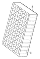
図9示すカセットの場合には、集積カセット140が滴下用トレー同様に形成されたグリッド状のウエル144の複数列から構成されている。このカセット140の足部は小さいのでカセット84上方の採集室の個数を増加することができる。またこのカセット140は採集された液相の貯蔵トレーとしても機能する。
【0143】
したがってビン36を交換したり別個の貯蔵領域からライナーをもってきたりする手間が省けて、交換過程における時間とコストとが節約される。蓋108と自動採集システムの機構を変更してやることにより、集積カセット140はそれ自身簡単な採集カセットおよび貯蔵トレーとして機能し、各サンプル注入間においてビン36を交換することなしに迅速にサンプルを収受できる。
【0144】
ロボットアーム80は、採集過程が終了した後またはウエル144が所望量の液相を含んだ後で、集積カセット140全体を交換できる。複数のカセット140が自動採集システムに貯蔵されると、自動過程中に多くの採集サンプルを与えることができる。好ましき集積カセットにおいては採集室列を深いウエルに収容したものが薬学業界において用いられる。
【0145】
このような型式によると、領域当たりにより多くの採集室が含まれるのみならずそれらの採集室が集積容易なので、貯蔵密度が改善されサンプル貯蔵能力が向上する。集積カセット140はプラスチック、樹脂またはステンレスなどの高強度材料から形成される。
【0146】
また集積カセット140は、ウエル144中に交換可能なビン36を含むことができるかまたはライナーを使わないこともできるので、採集サンプルをウエル144に直接収容でき、迅速なサンプル採集には有利である。ウエル144に液相が満たされた後はカセットは全体として交換できる。
【0147】
カセットトレーを用いた場合には図4のものと同じであるが若干変更がある。つまりラック86の代りにカセットトレーのための空間を具え、蓋108および制御器120および移送管66、68の寸法を工夫し、トレー140のための横方向制御器96の寸法を工夫し、採集中に採集室144間の切換えを行い、ロボットアーム80を変更して充填済みのトレー140を供給領域からの新たなトレーと交換するのである。また可動蓋108をロボットアーム80に連結して、トレーを動かすことなしに供給ラック中の採集室の各列に係合させるようにする。
【0148】
【発明の効果】
以上記載したようにこの発明のサンプル採集システムはいくつかの利点を具えている。例えば簡便化された予SFCサンプル採集を可能とし、注入されたサンプルから関心のある部分のみを採集することが可能であり、交換可能で安価で使捨て可能なビンに洗浄されたサンプルを採集でき、液相と気相との分離を効率よく行って98%にもおよびサンプル回収率を上げ、サンプルの採集や捕捉などに溶媒を必要としないので環境によくて経済的であり、別個の分離施設を必要とせず、高速で高体積で高純度の採集室採集が可能となる。
【図面の簡単な説明】
【図1】超臨界流クロマトグラフィー・システムを示す図式的流路図、およびこの発明の実施例としてのサンプルカセットを含む採集システムである。
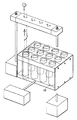
【図2】サンプル採集カセットを示す分解斜視図である。
【図3】カセット蓋の上面および底面を示す平面図である。
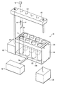
【図4】自動化された部分採集システムの、別の代表的実施例を示す平面図である。
【図5】自動化された部分採集システムの、別の代表的実施例を示す側面図である。
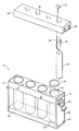
【図6】往復動作するサンプル採集カセット、蓋および機械化された動作制御システムを示す分解斜視図である。
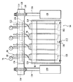
【図7】往復動作するカセット、および機械的制御装置を示す詳しい側面図である。
【図8】(A)ガラス試験管に移送管を挿入する前の状態を示す詳細断面図である。
(B)ガラス試験管に移送管を挿入後の状態を示す詳細断面図である。
【図9】多数列の採集室を有する、集積式採集カセットとしての別の実施例を示す。
【図10】自動化されたシステム用の往復動作する採集カセットとしての、追加的な別の実施例を示す。[0001]
This application claims the right to benefit from the application of preliminary supercritical flow chromatography filed on Sep. 16, 1999 according to
[0002]
BACKGROUND OF THE INVENTION
There is a basic industrial demand to recover highly purified components of interest from samples consisting of simple or complex mixtures of multiple components. Many techniques have been developed to meet this demand. The technique chosen for non-volatile components that can be eluted was liquid elution chromatography.
[0003]
Analysts have several goals in adopting preliminary elution chromatography (a method for separating a mixture into components). First, they want to get each component of interest as pure as possible. Second, they want to recover the maximum amount of each component of interest. Third, they want to process continuously and, if possible, want to remove samples unrelated to the first sample as quickly as possible and get an impurity-free one. Finally, what is often desired is a form that can be rapidly purified, either as a solvent-free component, or a well-defined solution that contains or contains the original collection solvent. The sample is collected as no solution.
[0004]
In normal phase chromatography, only an organic solvent or a mixture thereof is used as an eluent, and a typical volume ratio of several tens of milliliters per 100 milliliters is common. In order to recover the residual component of interest, that portion must then be evaporated for a significant amount of time.
[0005]
In reversed-phase chromatography, since a mixture of an organic solvent and water is used as an elution mobile phase, a secondary problem occurs. After removal of the low boiling solvent, the recovered portion must be removed from water overnight to several days. In this way, even after the separation process is completed, the recovery of the component of interest is delayed for several hours to several days. The latter problem can cause significant bottlenecks in the overall purification process when many samples are in line.
[0006]
When there are conditions that make it difficult to separate, or when the separation speed is important, one known as high performance liquid chromatography (HPLC), which is a kind of elution chromatography, is selected. This HPLC technique is used for both of the following purposes. In other words, it is used both as an analytical means for confirming each component and as a preliminary means for purifying and collecting these components.
[0007]
For HPLC as an analytical tool, the component level in the sample is typically in the nanogram to microgram range. HPLC systems as a preliminary measure typically handle microgram to several gram quantities of components per separation. The HPLC system as a preliminary means also requires a means to collect and store each part. This is usually done manually or automatically by simply switching the fluid flow of the system to a series of open containers.
[0008]
There are difficulties with HPLC as a current preliminary measure. Each sample requires an elution cycle in the range of minutes to hours. Moreover, even at optimal conditions, only a small proportion of the mobile phase contains the component of interest. This can lead to the generation of a very large, wasted mobile phase even if the system is operating normally.
[0009]
An alternative separation technique, called supercritical flow chromatography (SFC), has progressed over the past decade. SFC typically has carbon dioxide (CO 2 A highly compressible mobile phase is used. CO 2 In addition, the mobile phase often includes organic solvent modifiers to adjust the polarity of the mobile phase to optimal chromatographic (separate the mixture into components) performance.
[0010]
For different sample components, rapid elution requires different levels of organic modifier, so a common technique is to continuously increase the mobile phase composition by linearly increasing the organic modifier. Change. This technique is called gradient elution.
[0011]
For application as an analytical tool, SFC is demonstrating superiority in speed and solvency over traditional HPLC. This is a result of dramatically improved eluent diffusivity in the SFC mobile phase compared to the HPLC mobile phase.
[0012]
With the SFC device, separation continued to be achieved faster on the magnitude order (about 2.5 times for every step up) than the HPLC device using the same separation tube (chromatography column). The key factor for optimizing SFC separation is that the mobile phase flow, concentration and composition can be controlled independently throughout the entire separation process.
[0013]
The SFC device used with the gradient elution method also re-equilibrates much more quickly than the corresponding HPLC device. As a result, the device is ready to process the next sample after only a short time. The general gradient range in the gradient SFC technique is such that the composition of the organic modifier is in the range of 2% to 60%.
[0014]
CO 2 Even though an SFC device is designed to operate at temperatures and pressures above the critical point, it is typically suppressed from operating far below the critical point. It is worth noting that it is not. In this low range, especially when using organic modifiers, the chromatographic behavior remains superior to traditional HPLC and is often indistinguishable from true supercritical operation.
[0015]
In SFC as an analytical means, once separation occurs, the highly compressed mobile phase is directed to a fluid stream through a decompression step once detected. During decompression, CO in the mobile phase 2 The ingredients are allowed to expand dramatically and return to the gas phase. Its expansion and subsequent CO 2 The phase change tends to have a dramatic cooling effect on the waste stream element. If not careful, solid CO known as dry ice 2 May occur and clog the waste stream. To prevent this from occurring, heat is typically applied to the fluid stream. With a small flow rate in a typical analytical system, only a small amount of heat is required.
[0016]
CO in SFC mobile phase 2 Although the component immediately converts to a gaseous state, a moderately heated liquid organic modifier typically remains in the liquid phase. In general, the dissolved sample carried in the SFC system also remains in the dissolved liquid organic modifier phase.
[0017]
The principle that simple decompression of the mobile phase in SFC separates the flow into two parts is of great importance for using this technique in a preliminary manner. CO accounting for 50% to 95% of the mobile phase in normal operation 2 The removal of the gas phase significantly reduces the liquid collection volume for each component and, as a result, reduces the post-chromatographic throughput to recover the separated components.
[0018]
A high purity technique as a second analytical tool similar to SFC is supercritical flow extraction (SFE). In general, in this technique, the goal is to separate one or more components of interest from the solid matrix.
[0019]
SFE is a mass separation technique and does not necessarily attempt to separate the components extracted from the solid matrix individually. Determining the individual components typically requires a secondary separation step. Nevertheless, SFE shares a common goal with preliminary SFCs of collecting and recovering components of interest dissolved from supercritical fluid streams. As a result, a collection device suitable for preliminary SFC is also suitable for SFE techniques.
[0020]
To extend the SFC technique as an analytical tool to serve as a preliminary SFC, some adaptation is required for the device. First, the system requires increased flow. A flow rate of 20 mL / min to 200 mL / min is appropriate for separating material quantities ranging from a few milligrams to grams. In addition, a larger separation tube (column) is required. Finally, a collection system must be developed that allows at least a single part of the fluid stream to be collected, including the component of sufficient purity.
[0021]
In addition, there is often a hard-to-resist economic motive to make it possible to collect multiple parts from a single sample. The modified system must also be able to quickly re-initialize manually or automatically so that the next sample injection can follow the partial collection.
[0022]
Several commercial examples of preliminary SFC devices have been attempted that employ various levels of technology to solve collection problems. Representative sampling of these products includes those proposed by Gilson, Thar, Novasep, and ProChrom.
[0023]
However, none of the current instruments have been successful in providing instruments with high recoveries, high purity and low carry-over from sample to sample. For example, some systems use a naive method of simply spraying the collected stream directly into a large bottle, which results in significant sample loss, which may be due to aerosol formation.
[0024]
Another system uses a cyclone-like separator to separate the two streams, but does not have a quick or automatic cleaning means to clean the separator to prevent carryover. Such devices are typically employed for the purpose of separating large quantities of material by repeatedly injecting to eliminate the sample-to-sample wash step.
[0025]
Another system uses a collection solvent to take the sample portion into a volume of solvent contained in a collection container. This technique uses a relatively large amount of dangerous media to collect the sample, and tends to lose the concentration of the sample portion or cause quality degradation. There may be matrix interference between objects.
[0026]
An example of an SFC system is shown on the outside surrounded by a
[0027]
In the SFC system, liquefied carbon dioxide gas is supplied from the
[0028]
The combined supercritical flow is pumped at a controlled flow rate from the stirring
[0029]
SUMMARY OF THE INVENTION
One of the objects of this invention is to provide a partial collection device for supercritical fluid flow.
[0030]
It is a further object of the present invention to provide an apparatus that collects components obtained by subdividing a sample solution into one or more collection containers.
[0031]
The present invention relates to sample recovery after separation by supercritical flow chromatography, or supercritical flow extraction, and improvements thereof.
[0032]
More specifically, the present invention expands or reduces the pressure of a liquid phase containing a sample of a target component while controlling the mobile phase for separating one component from a high working pressure to an unstable low pressure. It relates to the separation from a much larger gas phase at optimal conditions. The controlled expansion causes phase separation between the liquid phase and the gas phase, while at the same time aerosol formation is strongly suppressed in the transfer tube.
[0033]
A further object of the present invention is to provide a single phase fluid, which is a mixture of a highly compressible or liquefied gas and a liquid organic modifier, in a transfer tube before collecting the liquid phase portion in one or more unique collection chambers. It is to provide an apparatus and a method for separating into a gas phase and a liquid phase. Collecting the liquid phase portion in this collection chamber minimizes the use and waste of liquid solvent through efficient separation of the gas phase and liquid phase prior to entering the collection chamber. This collection technique does not use additional solvent for partial collection.
[0034]
The present invention provides a multi-chamber cassette row for collecting and storing separated or extracted portions. Each collection cassette includes one or more collection chambers, each chamber capable of receiving a highly purified liquid portion.
[0035]
Each chamber can contain a removable sample collection liner (lining). The collection liner can be individually removed, replaced, stored, cleaned, reused or discarded. One purpose of this collection liner is to provide a simplified means for transferring the liquid portion collected from the cassette. The second purpose of this collection liner is to provide a means to remove cross turbidity between subsequent samples by preparing a clean liner that can be easily replaced for each sample in each collection chamber. It is to be.
[0036]
In the present invention, one or more valves for the collection chamber are provided so that a plurality of liquid phase portions from one sample can be collected in one or more collection chambers without mechanically adjusting the collection chamber seal. And the seal mechanism is controlled manually or automatically. This method allows rapid switching between collection chambers in the event of an approaching separation peak in the fluid stream separating the mixture into components.
[0037]
A further object of the present invention is to facilitate manual or automatic resetting of the collection system so that subsequent samples can be processed quickly. There are technical difficulties in realizing a collection system that satisfies all of the above-mentioned goals of the analysis engineers. The main problem is the supercritical CO of the compressed liquid or mobile phase that gasifies extremely under atmospheric pressure. 2 Concentrate around a portion of the part where there is significant expansion (typically 500 times). This change has four major negative effects on liquid phase sample collection.
[0038]
First, as mentioned above, the expanding CO 2 Causes a significant temperature drop, which can form dry ice and clog the system. Because the preliminary SFC is much faster than the corresponding analytical system, a significant amount of heat needs to be applied to compensate for this temperature drop.
[0039]
However, care must be taken: not to raise the actual temperature in the flow path system. This is because the temperature rise may damage the components that are thermally unstable. Increasing the ingredients of the organic regulator increases the heat capacity and CO 2 Both of these effects, which dissolves and thus prevents the formation of dry ice, alleviates the severity of this problem.
[0040]
Second, CO 2 When swells, the dissolving power it had in the compressed state disappears quickly. If the component of interest is solubility, CO 2 The component of interest will lose its means of transport through the original channel system. Solid components accumulate and eventually clog the flow path and cause system failure. Again, the organic modifier component is an important factor. Because the liquid continues to dissolve the components of interest and transfer them to the collection device. Care must be taken not to introduce excessive heat into the fluid stream since organically conditioned ones are also driven into the gas phase. Otherwise, the beneficial effect of transferring the solution is lost.
[0041]
Third, from the liquid to gaseous CO in the shortest possible time after the first decompression stage. 2 It is beneficial to complete the conversion to CO while in liquid state 2 Can disperse the organic modifier containing the component of interest even if it is not at a sufficient concentration to have outstanding dissolving power. This dispersion can have the effect of stirring the components efficiently separated by the SFC treatment prior to decompression. CO 2 The faster the is converted, the less the degradation of the function of separating into components.
[0042]
Liquid CO 2 Two factors appear to be dominant in the control of evaporation capacity. A) sufficient heat transfer between the heat source and the flowing liquid, and b) CO in the heated section 2 Stay time.
[0043]
The first factor can be influenced in a good direction by selecting a highly conductive material such as copper during heater fabrication. Ensuring good thermal contact between the heater and the transfer tube made of thin wall also facilitates heat transfer to the fluid stream.
[0044]
The dwell time of the fluid to be depressurized can be controlled by gradually reducing the pressure through one or more suppressors in series with the transfer tube. Increasing the back pressure decreases the linear velocity of the two-phase fluid in the heater. As long as the back pressure is generated by these suppressors, it does not interfere with the SFC concentration control in the high pressure separation region, and a large adjustment allowance for heat transfer optimization is possible.
[0045]
Fourth, due to expansion, the linear velocity of the reduced pressure fluid in the transfer tube increases dramatically. The residual liquid of this system is moved along the flow path by the shear force of the expanding gas. This spiral environment is ideal for aerosol generation, where microbubbles of the modifier liquid are carried away as “mist” into the gas phase. It is a discovery from this study that aerosol formation in the transfer tube can be almost completely controlled by appropriate temperature control of the expanding two-phase system. At lower temperatures, aerosol formation is a greater problem. Corresponding low level CO 2 It is a surprising finding from this study that higher levels of organic modifiers, including ingredients, require higher temperature levels to prevent visible aerosol formation.
[0046]
As a preferred exemplary embodiment, the SFC collection system consists of a moderately constrained, thermally controlled stainless steel transfer tube. This transfer tube extends from the pressure control element of the SFC chromatograph to the multi-port distribution valve and from there to various flow streams that lead directly to a separate collection chamber or a common waste container with vents. It extends to the road.
[0047]
CO 2 The initial separation of the liquid phase sample from the gas takes place immediately at the first reduced pressure location in the back pressure controller of the SFC or SFE device. By performing downstream suppression, solid CO 2 While maintaining a minimum back pressure sufficient to prevent the formation of liquid CO 2 Is present in the transfer tube.
[0048]
Remaining CO from organic modifier 2 Vaporization and separation takes place in a stainless steel transfer tube before entering the cassette. This is accomplished by contacting the transfer tube with one or more series of heaters designed to optimize heat transfer to the fluid. Ideally, this series of heaters will generate sufficient energy to generate a fluid liquid CO. 2 Transmitted to the part, its liquid CO 2 The temperature of the fluid is raised sufficiently to evaporate the part completely and to prevent external freezing of the transfer tube. Since the rate of heat transfer is time dependent, it is beneficial to reduce the fluid velocity in the series of heaters.
[0049]
CO in the first heating zone 2 During the evaporation process, gaseous CO 2 There is considerable separation between the liquid regulator and the liquid modifier. But for several reasons, pure CO 2 And separation into liquid regulators is not realized.
[0050]
First, typically small amounts of organic modifiers also evaporate to a gaseous state. The degree of evaporation largely depends on the absolute temperature of the fluid in the transfer tube. Although the recovery of the liquid phase decreases when the organic modifier evaporates, the recovered amount of the dissolved component of interest does not necessarily decrease because the boiling point is typically not so low that the organic modifier converts to vapor.
[0051]
Second, some part of CO 2 Remains dissolved in the organic liquid. Both temperature and pressure depend on residual CO 2 Determine the amount of. CO at high temperatures 2 The solubility of CO decreases, but at high pressures CO 2 Increase in solubility.
[0052]
Aerosol formation in the liquid phase is a common problem in SFC sample collection and is a major cause of erosion of the organic liquid phase containing dissolved components of interest. At higher temperatures, aerosol formation is reduced. The composition of the separated phases is also a factor. Higher temperatures are required for aerosol removal in fluids containing higher concentrations of organic liquid phase. An additional heating zone is used for the purpose of adjusting fluid temperature for aerosol control. In addition, prior to collection in a pressurized collection chamber, this heater allows the fluid temperature to be controlled at a precise level.
[0053]
As described above, the secondary effects are as follows. A high level of temperature control is achieved with dissolved CO 2 Concentration can be reduced, so that when pressure is removed from the collection chamber, uncontrolled or explosive CO 2 The possibility of gas generation can be reduced.
[0054]
A valve system is used to switch the path of the two-phase fluid flow, following the conditioning heater, continuously to the waste stream or to one of the collection chambers in the collection cassette. This valve system consists of one or more valves and an electrical controller.
[0055]
This system is designed to provide a quick response to manual or automatic start / stop signals. Typically, this signal is based on the result of detecting a component of interest coming out of the high pressure fluid system.
[0056]
The start signal is issued when the first component is detected, while the stop signal is issued when the detection is lost. The effect of the start signal is to switch the fluid flow path to one of the first unused collection chambers in the cassette. The effect of the stop signal is to switch the fluid flow path to the waste stream.
[0057]
Another possible start / stop signal format is based on timetables rather than physical detection of components. The controller may also have a form that limits the access time or limits the allowable flow to each chamber. In addition, the controller can allow or block the system from returning to the first room if more parts are desired than there are currently available collection rooms.
[0058]
A collection cassette is a resealable device that includes one or more hollow collection chambers open at the top. As a preferred exemplary embodiment according to this invention, each chamber can hold an inert liner that can be removed. The liner collects a portion of the initial sample dissolved in the liquid solvent base. A preferred exemplary embodiment cassette has four chambers as a case containing four glass test tubes that function as chamber liners. The number of chambers in the cassette can be increased or decreased regardless of performance. Each glass test tube can hold up to its capacity a sample portion separated from the high pressure fluid stream.
[0059]
In a preferred embodiment, the sample portion is collected in a chamber of the cassette at one time. Two-phase fluid enters the chamber from the valve system via a transfer tube. The tip of the transfer tube is preferably perpendicular to the inner wall of the collection tube and slightly downward, usually 45 degrees or less from the horizontal.
[0060]
A guide spring wire is wound around the transfer tube and hung inside the test tube. This spring wire is bent so as to protrude from the transfer tube, and serves as a guide when the transfer tube descends into the glass tube. When the transfer tube is successfully inserted into the glass test tube, the bent portion of the spring wire hits the outer peripheral edge of the open end of the glass test tube. As the transfer tube continues to descend into the glass tube, the spring wire applies pressure to the inner surface of the glass test tube and pushes the transfer tube toward the opposite side of the glass tube. As a result, the tip of the angled transfer tube is pressed against the inner surface of the glass test tube.
[0061]
Organic liquid and CO 2 Both gases descend down the spiral passage along the inner wall and travel to the bottom of the collection liner. The liquid is collected at this point and begins to fill the liner. Its CO 2 The gas continues to rise up the passage in the center of the liner toward the collection chamber exhaust hole. A constraining transfer tube attached to the exhaust vents, both inside and outside the collection liner, 2 Gas causes high pressure in the collection chamber. The extent to which back pressure is applied to the collection chamber is determined by the initial mobile phase CO. 2 It is roughly proportional to the composition.
[0062]
The high pressure in the collection room is due to the CO entering the collection room. 2 Helps reduce gas velocity. In other words, CO at the bottom of the liner 2 Reduce the amount of shear that occurs between the gas and the collected liquid. A low shear force reduces the tendency of the collected liquid to become an aerosol and reduces the tendency to be removed with the active gas from the collection tube. A similar effect can be obtained by appropriately angling the infusion transfer tube relative to the wall of the collection tube. The smaller the angle of the transfer tube is near horizontal, the fewer spirals are observed on the liquid surface. However, a sufficient angle must be provided to ensure that most of the effluent is directed downward rather than upward on the liner wall.
[0063]
Suppressing aerosol formation in the collected liquid part combines two effects: back pressure and injection angle. To successfully optimize these effects, you can determine how close you can place the injection tube to the collection solution, so that the liner fills well before sample loss becomes a problem. Complete. When the flow to the collection chamber stops, the chamber is depressurized. Once the sample chamber is depressurized, the liner can be removed by opening the top lid of the cassette.
[0064]
Collecting the portion into the disposable liner of the collection room can be automated using a robot. In the automation system, the glass test tube can be quickly replaced into and out of the collection chamber, and a large number of glass tubes for replacement can be prepared to enable unmanned operation for a long time. A programmable robot automatically arranges the cassettes in a certain order at sample injection intervals, thus speeding up the process and reducing the potential for errors. This automated system allows partial collection of thousands of orders per month.
[0065]
The automation system is housed in a laboratory grade case. The system includes a robotic arm, an inventory of glass test tubes placed upward in the rack, and an automated version of the cassette assembly. In addition, the system may include sufficient probes, valves, and sample containers to achieve automatic injection of unseparated samples into a chromatography or extraction system.
[0066]
The collection cassette and its automated mechanism are designed for rapid sample collection and the shortest downtime of the chamber liner change interval. The cassette in the preferred embodiment has two rows, each with four collection chambers. A lid is placed above a row of collection chambers in the cassette. The lid has four partially recessed holes corresponding to the four collection chambers in the cassette. The lid is mounted on the base of the case and is raised and lowered by the movement of the pneumatic actuator located at both ends in the longitudinal direction of the lid. As each actuator simultaneously lowers the lid onto the collection cassette, the upper end of each chamber engages the bottom edge of the lid, corresponding to the respective rim of the partially recessed hole.
[0067]
The lid and collection chamber engage to form a pressure-tight seal in each chamber that is in standby for sample partial collection. The lid has a transfer pipe and a waste pipe that pass through each recessed hole corresponding to each collection chamber. Each tube pair (transfer tube and waste tube) enters the test tube when its lid is lowered onto the cassette.
[0068]
A spring wire wrapped around the injection transfer tube leads the injection transfer tube into the glass test tube. The tip of the angled transfer tube is pressed against the inner surface of the test tube. When the lid seals the collection chamber row, the valve system distributes the flow convection, including the gas and liquid phases, from the sample subdivision process to the chamber liner.
[0069]
When all test tubes in the pressurized cassette row are filled and depressurized, the lid lifts away from the cassette. The cassette then moves sideways or reciprocates, and the empty collection chamber liner moves to the bottom of the lid, replacing the previous row. The cassette is constrained to reciprocate laterally along a passage on the case base.
[0070]
The lid is lowered and engages a new collection chamber row, so that a test tube is prepared to receive the sample portion. On the other hand, the previous row of collection chamber liner glass test tubes, including the liquid portion, is removed from the collection chamber and moved by the robot arm to an empty space in the storage tray.
[0071]
In summary, in a preferred embodiment, the sample is dissolved in a minimal volume of modifier solution and collected in a liner that can be removed and reused. By adjusting the flow rate, velocity, temperature, and pressure in the system, excellent separation of near-supercritical elution fluid was obtained. A collection efficiency as high as 98% of the injected sample components was achieved.
[0072]
In this process, a cassette with a pressurized collection chamber and a disposable liner minimizes the amount of additional solvent for collection and cleaning used in the laboratory, which is economical and environmentally friendly. Labs and laboratories that require sample purity while wanting to maximize yield and minimize waste will benefit from this invention. Thousands of large sample subdivisions and collections per month can be realized with this exemplary embodiment.
[0073]
In order to better understand the nature of the present invention, it will be described in detail with reference to the following drawings. Here, similar reference numerals are assigned to similar elements.
[0074]
【Example】
In FIG. 1, a
[0075]
In one embodiment, the SFC collection system includes a temperature controlled
[0076]
The expansion waste liquid leaving the
[0077]
The initial separation of the liquid phase from carbon dioxide occurs at the time of initial decomposition in the
[0078]
CO from organic regulators 2 Further separation and evaporation occurs in the
[0079]
CO in the first heating zone 2 During the evaporation process, gas phase CO 2 There is significant separation between the liquid phase modifier. But pure CO 2 The separation into pure modifiers is never observed. The degree of evaporation greatly depends on the absolute temperature of the fluid in the
[0080]
The evaporation of the organic modifier leads to a decrease in the collection of the liquid phase when it reaches the collection cassette, but it is not necessarily the time of the component of interest (generally not having a low enough evaporation point to transform above). It does not reduce the collection. CO 2 Part of this remains dissolved in the organic modifier. Temperature and pressure are residual CO 2 Determine the amount of. The higher the temperature, the more CO 2 The solubility of CO decreases, but the higher the pressure, the more CO 2 Increase in solubility.
[0081]
Vapor phase CO in a narrow transfer tube 2 The turbulent flow generates a strong shear force that drives the fluid down the wall of the
[0082]
A plurality of heaters may be connected to heat the waste fluid. In the embodiment of FIG. 1, the evaporating
[0083]
The waste fluid is heated within the control temperature (about 5-50 ° C.) of the
[0084]
The speed of the fluid passing through the
[0085]
Further, the back pressure is sufficiently increased by the
[0086]
After exiting the
[0087]
The
[0088]
The
[0089]
In the embodiment of FIG. 2, the cassette 24 has four
[0090]
The
[0091]
Each
[0092]
The bin 36 functions as a disposable liner for the
[0093]
The cassette 24 shown in FIG. 2 has a square frame for fixing four
[0094]
As shown in FIG. 1, a transfer pipe or
[0095]
3A and 3B show the top and bottom of the
[0096]
The diameter of the
[0097]
[0098]
The
[0099]
In the preferred embodiment, a small amount is collected in the
[0100]
A similar effect can be obtained by angling the transfer pipe on the inflow side to the
[0101]
Two-phase waste fluid enters
[0102]
When the
[0103]
The spring 70 is extruded from an inert material and does not chemically interfere with the sample collected in the
[0104]
Organic liquid and CO 2 Flows to the bottom of the
[0105]
The back pressure and delivery angle synergize to reduce aerosol formation in the collected liquid portion. Optimizing these effects will determine how close the
[0106]
A
[0107]
The volume of the
[0108]
This signal is derived from the detection of the component coming out of the high pressure flow system. The start signal is generated by initial detection of the component, and the end signal is generated when detection is lost. When a termination signal is given, the fluid flow is directed to the
[0109]
The controller may constrain the access time allowed for each
[0110]
4-7 show a modified embodiment of the cassette and system. This is an automatic system using a
[0111]
The
[0112]
4 and 5 show another embodiment of an automated SFC sample collection system. The elements of the system are partially disposed on a base 88 in the
[0113]
The supply of
[0114]
The
[0115]
The
[0116]
The
[0117]
[0118]
The
[0119]
The
[0120]
The
[0121]
The
[0122]
The track not only causes movement of the
[0123]
In FIGS. 6 and 7, the
[0124]
However, high density plastics or similar synthetic and composition materials are also effective. The
[0125]
The movement of each
[0126]
In FIG. 7, the
[0127]
The diameter of each
[0128]
Positioning pins 124 are disposed on both sides of the row of the
[0129]
The
[0130]
This
[0131]
The internal pressure of the portion surrounding the
[0132]
As shown in FIG. 7, the closed lower end of each
[0133]
The
[0134]
The
[0135]
In addition to the transfer pipe, the pressure in the collection chamber can be measured by a
[0136]
The tip of the
[0137]
Such a structure of the
[0138]
A Cartesian or three-dimensional robot arm may be programmed to move the bin between the supply rack and the collection room. 4 and 5, a
[0139]
The jaw 92 grips the
[0140]
The movement of the
[0141]
[0142]
In the case of the cassette shown in FIG. 9, the
[0143]
This saves the time and cost of the replacement process by eliminating the need to replace the
[0144]
The
[0145]
According to such a type, not only more collection chambers are included per area but also the collection chambers are easily integrated, so that the storage density is improved and the sample storage capacity is improved. The
[0146]
[0147]
When a cassette tray is used, it is the same as that shown in FIG. That is, a space for the cassette tray is provided instead of the
[0148]
【The invention's effect】
As described above, the sample collection system of the present invention has several advantages. For example, simplified pre-SFC sample collection is possible, it is possible to collect only the part of interest from the injected sample, and it is possible to collect samples that have been washed into replaceable, inexpensive and disposable bottles. Efficient separation between the liquid phase and the gas phase increases the sample recovery rate to 98%, and does not require a solvent for sample collection or capture. It is possible to collect high-quality, high-volume collection rooms at high speed without the need for facilities.
[Brief description of the drawings]
FIG. 1 is a schematic flow diagram showing a supercritical flow chromatography system, and a collection system including a sample cassette as an embodiment of the present invention.
FIG. 2 is an exploded perspective view showing a sample collection cassette.
FIG. 3 is a plan view showing an upper surface and a bottom surface of the cassette lid.
FIG. 4 is a plan view showing another exemplary embodiment of an automated partial collection system.
FIG. 5 is a side view of another exemplary embodiment of an automated partial collection system.
FIG. 6 is an exploded perspective view showing a reciprocating sample collection cassette, a lid, and a mechanized motion control system.
FIG. 7 is a detailed side view showing a reciprocating cassette and a mechanical control device.
FIG. 8A is a detailed cross-sectional view showing a state before a transfer tube is inserted into a glass test tube.
(B) It is detailed sectional drawing which shows the state after inserting a transfer pipe into a glass test tube.
FIG. 9 shows another embodiment as an integrated collection cassette with multiple rows of collection chambers.
FIG. 10 shows an additional alternative embodiment as a reciprocating collection cassette for an automated system.
Claims (59)
Applications Claiming Priority (2)
| Application Number | Priority Date | Filing Date | Title |
|---|---|---|---|
| US09/607,316 US6413428B1 (en) | 1999-09-16 | 2000-06-26 | Apparatus and method for preparative supercritical fluid chromatography |
| US09/607316 | 2000-06-26 |
Related Child Applications (1)
| Application Number | Title | Priority Date | Filing Date |
|---|---|---|---|
| JP2007258688A Division JP4918641B2 (en) | 2000-06-26 | 2007-10-02 | Method and apparatus for collecting samples from fluid streams |
Publications (2)
| Publication Number | Publication Date |
|---|---|
| JP2002071534A JP2002071534A (en) | 2002-03-08 |
| JP4049552B2 true JP4049552B2 (en) | 2008-02-20 |
Family
ID=24431749
Family Applications (2)
| Application Number | Title | Priority Date | Filing Date |
|---|---|---|---|
| JP2001184357A Expired - Fee Related JP4049552B2 (en) | 2000-06-26 | 2001-06-19 | Method and apparatus for collecting samples from fluid streams |
| JP2007258688A Expired - Fee Related JP4918641B2 (en) | 2000-06-26 | 2007-10-02 | Method and apparatus for collecting samples from fluid streams |
Family Applications After (1)
| Application Number | Title | Priority Date | Filing Date |
|---|---|---|---|
| JP2007258688A Expired - Fee Related JP4918641B2 (en) | 2000-06-26 | 2007-10-02 | Method and apparatus for collecting samples from fluid streams |
Country Status (7)
| Country | Link |
|---|---|
| US (3) | US6413428B1 (en) |
| EP (2) | EP1170057B1 (en) |
| JP (2) | JP4049552B2 (en) |
| AT (1) | ATE463293T1 (en) |
| CA (1) | CA2347514C (en) |
| DE (1) | DE60141732D1 (en) |
| MX (1) | MXPA01006438A (en) |
Cited By (2)
| Publication number | Priority date | Publication date | Assignee | Title |
|---|---|---|---|---|
| JP2011191216A (en) * | 2010-03-15 | 2011-09-29 | Toshiba Corp | Automatic analyzer |
| US10155745B2 (en) | 2013-04-12 | 2018-12-18 | Obschestvo S Ogranichennoi Otvetstvennostiyu “Pharmenterprises” | Glutarimide derivatives, use thereof, pharmaceutical composition based thereon and methods for producing glutarimide derivatives |
Families Citing this family (70)
| Publication number | Priority date | Publication date | Assignee | Title |
|---|---|---|---|---|
| US6893877B2 (en) * | 1998-01-12 | 2005-05-17 | Massachusetts Institute Of Technology | Methods for screening substances in a microwell array |
| SE9901722D0 (en) * | 1999-05-12 | 1999-05-12 | Amersham Pharm Biotech Ab | Device for reducing loss of liquid during fraction collection |
| US6685828B2 (en) * | 1999-09-16 | 2004-02-03 | Berger Instruments, Inc. | Automated sample collection in supercritical fluid chromatography |
| US6632353B2 (en) * | 2000-06-26 | 2003-10-14 | Berger Instruments, Inc. | Rapid sample collection in supercritical fluid chromatography |
| US9125989B2 (en) * | 2003-01-23 | 2015-09-08 | Debiotech S.A. | Device for determining the characteristics of peritoneal membrane |
| US6648609B2 (en) * | 2002-04-05 | 2003-11-18 | Berger Instruments, Inc. | Pump as a pressure source for supercritical fluid chromatography involving pressure regulators and a precision orifice |
| US6908557B2 (en) * | 2002-06-25 | 2005-06-21 | Thar Technologies, Inc. | Collection system for chromatographic system |
| CN100425525C (en) * | 2003-11-18 | 2008-10-15 | 鸿富锦精密工业(深圳)有限公司 | Nano-super fluid |
| JP4319551B2 (en) * | 2004-01-05 | 2009-08-26 | ダイセル化学工業株式会社 | Separation method of substances by supercritical fluid chromatography and gas-liquid separation apparatus used therefor |
| US20060188397A1 (en) * | 2005-01-07 | 2006-08-24 | Lalit Chordia | Method and apparatus for fraction collection |
| US20070163962A1 (en) * | 2006-01-13 | 2007-07-19 | Bidlingmeyer Brian A | Fraction collection in high performance liquid chromatography |
| US7964029B2 (en) * | 2006-07-17 | 2011-06-21 | Thar Instrument, Inc. | Process flowstream collection system |
| US7909993B2 (en) * | 2007-01-09 | 2011-03-22 | Modular Sfc, Llc | Centrifugal fraction collection system and method |
| US7905133B2 (en) * | 2007-12-28 | 2011-03-15 | Thar Instruments, Inc. | Variable ratio flow splitter for a flowstream |
| US9163618B2 (en) * | 2008-06-24 | 2015-10-20 | Agilent Technologies, Inc. | Automated conversion between SFC and HPLC |
| US8215922B2 (en) | 2008-06-24 | 2012-07-10 | Aurora Sfc Systems, Inc. | Compressible fluid pumping system for dynamically compensating compressible fluids over large pressure ranges |
| WO2010019216A1 (en) * | 2008-08-11 | 2010-02-18 | Modular Sfc, Llc | Fraction collector diverter valve |
| JP4675406B2 (en) | 2008-09-29 | 2011-04-20 | 日本分光株式会社 | Sample collection container, sample collection device, and sample collection method in a supercritical fluid system |
| US9205350B2 (en) * | 2008-11-12 | 2015-12-08 | Waters Technologies Corporation | Collection system for purification flowstreams |
| JP5170304B2 (en) | 2009-03-31 | 2013-03-27 | 株式会社島津製作所 | Preparative purification equipment |
| JP2011122941A (en) * | 2009-12-10 | 2011-06-23 | Central Res Inst Of Electric Power Ind | Automatic water sampler |
| US8419936B2 (en) | 2010-03-23 | 2013-04-16 | Agilent Technologies, Inc. | Low noise back pressure regulator for supercritical fluid chromatography |
| US9114330B2 (en) | 2010-09-20 | 2015-08-25 | Agilent Technologies, Inc. | System and process for an active drain for gas-liquid separators |
| WO2013062635A2 (en) * | 2011-06-14 | 2013-05-02 | Agilent Technologies, Inc. | Automated conversion between sfc and hplc |
| EP2720769B1 (en) | 2011-06-17 | 2020-07-29 | Waters Technologies Corporation | Methods and devices for open-bed atmospheric collection in supercritical fluid chromatography |
| US20130333467A1 (en) * | 2012-06-19 | 2013-12-19 | Waters Technologies Corporation | Measuring Fluid Density |
| KR101270669B1 (en) * | 2012-11-07 | 2013-06-03 | 대한민국 | A chamber apparatus for pollutant emission tests of specimen |
| US9766214B2 (en) | 2012-11-28 | 2017-09-19 | Shimadzu Corporation | Supercritical fluid processing device |
| CA2910137C (en) * | 2013-04-22 | 2021-06-22 | Morin Enertech Inc. | Compound sampling system and method for sampling a compound using same |
| JP5451924B1 (en) | 2013-05-08 | 2014-03-26 | 株式会社アルテ | Manufacturing method of two-chamber type syringe |
| US11913685B2 (en) | 2014-08-19 | 2024-02-27 | Supercritical Fluid Technologies, Inc. | Cooling loop with a supercritical fluid system using compressed refrigerant fluid flow with a positive Joule Thomson coefficient |
| US10765968B2 (en) | 2014-08-19 | 2020-09-08 | Supercritical Fluid Technologies, Inc. | Systems and methods for supercritical fluid chromatography |
| EP4145125B1 (en) | 2014-08-19 | 2025-10-01 | Supercritical Fluid Technologies, Inc. | Supercritical fluid chromatography system |
| CN104229478A (en) * | 2014-09-10 | 2014-12-24 | 福建紫杉园生物有限公司 | Wind-driven feeding device for extracting paclitaxel from Chinese yew branches and leaves |
| WO2016046990A1 (en) * | 2014-09-26 | 2016-03-31 | 株式会社島津製作所 | Sample collection device, supercritical fluid device, and sample collection method |
| BR112017005703A2 (en) | 2014-10-27 | 2018-01-23 | F. Hoffmann-La Roche Ag | chromatography system and method for separating a sample |
| WO2016088252A1 (en) * | 2014-12-05 | 2016-06-09 | 株式会社島津製作所 | Sample collection mechanism and supercritical fluid device provided with said sample collection mechanism |
| JP6489129B2 (en) * | 2014-12-11 | 2019-03-27 | 株式会社島津製作所 | Method and sample recovery mechanism for sample flowing out from supercritical fluid device |
| CN107107076B (en) | 2015-01-30 | 2019-11-08 | 安捷伦科技有限公司 | Impact centrifugal separator, manufacturing method thereof, and fraction collection system |
| JP6332550B2 (en) * | 2015-03-19 | 2018-05-30 | 株式会社島津製作所 | Supercritical fluid device |
| CN104790912A (en) * | 2015-04-10 | 2015-07-22 | 中国石油大学(北京) | Automatic chemical adding device for oil wellhead and chemical adding method |
| CN106267890A (en) * | 2015-06-03 | 2017-01-04 | 中美华世通生物医药科技(武汉)有限公司 | Controllable compression tomographic system and chromatography method |
| CN104888880B (en) * | 2015-06-16 | 2017-03-15 | 朱红 | A kind of use for laboratory Multifunctional gas collection bottle support |
| JP6264500B2 (en) * | 2015-10-02 | 2018-01-24 | 株式会社島津製作所 | Sample collection device, supercritical fluid device, and sample collection method |
| CN105572266B (en) * | 2016-03-04 | 2017-07-18 | 聊城大学 | A kind of method for preparing supercritical fluid chromatograph and being purified for preparative separation with multiple-way valve |
| CN105784859B (en) * | 2016-03-04 | 2017-12-26 | 聊城大学 | It is a kind of to isolate and purify preparative chromatograph and the method for preparative separation purifying |
| CN105738638B (en) * | 2016-05-12 | 2019-06-04 | 利多(香港)有限公司 | Thermal insulation shell for analyzer |
| US10259023B2 (en) * | 2016-05-31 | 2019-04-16 | Jones Ofori | Processing basket and probes disposable utility lining system |
| WO2018071884A1 (en) | 2016-10-14 | 2018-04-19 | Supercritical Fluid Technologies, Inc. | Cooling loop with a supercritical fluid system using compressed refrigerant fluid flow with a positive joule-thomson coefficient |
| CN106422981A (en) * | 2016-11-22 | 2017-02-22 | 西南石油大学 | High-temperature high-pressure reaction device and method for researching chemical water shutoff agent for oilfield water shutoff |
| CN106730995A (en) * | 2016-12-14 | 2017-05-31 | 天长市康宁甘油科技有限公司 | A kind of glycerine continuous stripping purifier |
| US10549214B2 (en) | 2017-03-10 | 2020-02-04 | Savannah River Nuclear Solutions, Llc | Device for residue handling minimization with vacuum-assisted separations |
| KR102358561B1 (en) | 2017-06-08 | 2022-02-04 | 삼성전자주식회사 | Substrate processing apparatus and apparatus for manufacturing integrated circuit device |
| WO2020142753A1 (en) | 2019-01-04 | 2020-07-09 | Supercritical Fluid Technologies, Inc. | Interchangeable chromatography cartridge adapter system |
| CN109739282A (en) * | 2019-01-18 | 2019-05-10 | 中国石油集团长城钻探工程有限公司录井公司 | A kind of lighter hydrocarbons well logging constant-temperature control method |
| CN110354530A (en) * | 2019-07-29 | 2019-10-22 | 湖南正清制药集团股份有限公司 | Extract the second level counterflow centrifugal extraction tele-control system and method for cucoline |
| CN110538679B (en) * | 2019-08-19 | 2025-01-14 | 昆山汇先医药技术有限公司 | A robotic arm pipetting system for microfluidic sample processing equipment |
| CN110560196B (en) * | 2019-09-06 | 2024-07-26 | 中国计量大学 | Heavy metal detection sample pretreatment workbench |
| CN110631890B (en) * | 2019-10-31 | 2022-06-17 | 上海屹尧仪器科技发展有限公司 | Full-automatic sample pretreatment platform taking microwave digestion as core |
| JPWO2021193418A1 (en) * | 2020-03-24 | 2021-09-30 | ||
| CN112326981A (en) * | 2020-09-30 | 2021-02-05 | 迈克医疗电子有限公司 | Sample analysis apparatus and sample analysis method |
| DE102020134836B3 (en) | 2020-12-23 | 2022-03-24 | LCTech GmbH | Extraction system for extracting analytes from a sample |
| CN112834667A (en) * | 2020-12-31 | 2021-05-25 | 贵州电网有限责任公司 | A transformer oil chromatographic sampling device |
| CN112781938A (en) * | 2020-12-31 | 2021-05-11 | 杭州乐载科学仪器有限公司 | Analysis device and method for condensation collection and determination of soluble ions in air |
| CN113009094B (en) * | 2021-02-03 | 2023-07-07 | 禄根仪器(镇江)有限公司 | A New Type of High Efficiency Drug Dissolution Apparatus |
| CN113188843B (en) * | 2021-05-10 | 2022-09-02 | 江西怡杉环保股份有限公司 | Water quality sampling equipment |
| US12134099B2 (en) * | 2021-06-01 | 2024-11-05 | Invetech Ip Llc | Needle-less access vial and cap for the aseptic sampling and storage of liquids |
| CN113588338A (en) * | 2021-07-12 | 2021-11-02 | 桂林云璟科技有限公司 | Sample collection and storage device and flow path for same |
| KR102762744B1 (en) * | 2022-01-18 | 2025-02-06 | 한국원자력안전기술원 | Automated collection system of extract solution and precipitation using multi-channel tubing pump |
| KR102671278B1 (en) * | 2022-03-29 | 2024-05-31 | 한국원자력연구원 | Fluid collector device and radionuclide separation system including the same |
Family Cites Families (31)
| Publication number | Priority date | Publication date | Assignee | Title |
|---|---|---|---|---|
| DE1221036B (en) | 1962-12-24 | 1966-07-14 | Abcor Inc | Chromatographic separation column |
| US4168955A (en) * | 1977-03-28 | 1979-09-25 | Instrumentation Specialties Company | Chemical analyzer |
| DE2843920A1 (en) | 1978-10-09 | 1980-04-10 | Krupp Gmbh | METHOD FOR TREATING RAW PLANT FATS AND OILS |
| FR2527934A1 (en) * | 1982-06-03 | 1983-12-09 | Elf Aquitaine | METHOD OF FRACTIONING BLENDS BY ELUTION CHROMATOGRAPHY WITH SUPERCRITICAL FLUID AND INSTALLATION FOR ITS IMPLEMENTATION |
| US4880543A (en) * | 1987-08-31 | 1989-11-14 | Aluminum Company Of America | Supercritical fluid chromatography packing material containing alumina |
| US5087360A (en) * | 1990-04-19 | 1992-02-11 | Electric Power Research Institute, Inc. | Field-portable apparatus and method for analytical supercritical fluid extraction of sorbent materials |
| US4962662A (en) | 1988-02-17 | 1990-10-16 | Hewlett-Packard Company | Supercritical fluid chromatography |
| US4814089A (en) * | 1988-02-17 | 1989-03-21 | Suprex Corporation | Chromatographic separation method and associated apparatus |
| US4845985A (en) | 1988-02-17 | 1989-07-11 | Hewlett-Packard Company | Supercritical fluid chromatography |
| US5151178A (en) * | 1989-02-27 | 1992-09-29 | Hewlett-Packard Company | Axially-driven valve controlled trapping assembly |
| US5009778A (en) * | 1989-02-27 | 1991-04-23 | Hewlett-Packard Company | Axially-driven valve controlled fluid trapping assembly |
| US5178767A (en) * | 1989-02-27 | 1993-01-12 | Hewlett-Packard Company | Axially-driven valve controlled trapping assembly |
| US4892654A (en) * | 1989-03-15 | 1990-01-09 | Nickerson Mark A | Trapping assembly |
| JPH0445543A (en) * | 1990-06-13 | 1992-02-14 | Mitsubishi Electric Corp | Manufacture method of semiconductor device |
| JPH0457245A (en) * | 1990-06-21 | 1992-02-25 | Mitsubishi Electric Corp | Cassette loading/unloading device |
| US5614089A (en) * | 1990-07-13 | 1997-03-25 | Isco, Inc. | Apparatus and method for supercritical fluid extraction or supercritical fluid chromatography |
| US5601707A (en) | 1990-07-13 | 1997-02-11 | Isco, Inc. | Apparatus and method for supercritical fluid extraction or supercritical fluid chromatography |
| US5269930A (en) * | 1990-07-13 | 1993-12-14 | Isco, Inc. | Apparatus and method for supercritical fluid extraction |
| US5139681A (en) | 1990-10-09 | 1992-08-18 | The Dow Chemical Company | On-line multidimensional chromatographic system with large volume injection handling for supercritical fluid chromatography |
| US5234599A (en) | 1990-10-09 | 1993-08-10 | The Dow Chemical Company | On-line multidimensional chromatographic system with large volume injection handling for supercritical fluid chromatography |
| US5264184A (en) * | 1991-03-19 | 1993-11-23 | Minnesota Mining And Manufacturing Company | Device and a method for separating liquid samples |
| US5198115A (en) | 1991-07-09 | 1993-03-30 | Analytical Bio-Chemistry Laboratories, Inc. | Integrated instrument for supercritical fluid sample extraction, sample separation and concentration |
| EP0551594B1 (en) * | 1992-01-10 | 1996-02-21 | Hewlett-Packard Company | High efficiency packed column supercritical fluid chromatography |
| US5458783A (en) * | 1992-08-13 | 1995-10-17 | Suprex Corporation | Supercritical fluid extraction coupled to analytical chromatography system |
| US5346622A (en) * | 1993-03-04 | 1994-09-13 | Hewlett-Packard Company | Hydrocarbon class separation and quantitation by split column effluent analysis |
| US5843311A (en) | 1994-06-14 | 1998-12-01 | Dionex Corporation | Accelerated solvent extraction method |
| GB9413875D0 (en) * | 1994-07-09 | 1994-08-31 | British Nuclear Fuels Plc | Separating solutes from solutions |
| US5549819A (en) * | 1995-01-17 | 1996-08-27 | Hewlett-Packard Company | Portable extraction instrument |
| US6890491B1 (en) * | 1997-06-10 | 2005-05-10 | Pharmacopeia Drug Discovery, Inc. | Method and apparatus for universal fluid exchange |
| DE19858507B4 (en) * | 1997-12-19 | 2004-02-12 | Forschungszentrum Karlsruhe Gmbh | Process for the extraction of contaminants from fillings using supercritical fluids |
| US5996818A (en) | 1998-11-24 | 1999-12-07 | Lab-Interlink, Inc. | Specimen tube rack |
-
2000
- 2000-06-26 US US09/607,316 patent/US6413428B1/en not_active Expired - Lifetime
-
2001
- 2001-05-14 CA CA002347514A patent/CA2347514C/en not_active Expired - Fee Related
- 2001-06-19 JP JP2001184357A patent/JP4049552B2/en not_active Expired - Fee Related
- 2001-06-22 MX MXPA01006438A patent/MXPA01006438A/en unknown
- 2001-06-25 AT AT01115331T patent/ATE463293T1/en not_active IP Right Cessation
- 2001-06-25 EP EP01115331A patent/EP1170057B1/en not_active Expired - Lifetime
- 2001-06-25 EP EP09181036A patent/EP2184093A1/en not_active Ceased
- 2001-06-25 DE DE60141732T patent/DE60141732D1/en not_active Expired - Lifetime
-
2002
- 2002-02-04 US US10/066,955 patent/US6656354B2/en not_active Expired - Lifetime
- 2002-02-04 US US10/067,011 patent/US6652753B2/en not_active Expired - Lifetime
-
2007
- 2007-10-02 JP JP2007258688A patent/JP4918641B2/en not_active Expired - Fee Related
Cited By (7)
| Publication number | Priority date | Publication date | Assignee | Title |
|---|---|---|---|---|
| JP2011191216A (en) * | 2010-03-15 | 2011-09-29 | Toshiba Corp | Automatic analyzer |
| US10155745B2 (en) | 2013-04-12 | 2018-12-18 | Obschestvo S Ogranichennoi Otvetstvennostiyu “Pharmenterprises” | Glutarimide derivatives, use thereof, pharmaceutical composition based thereon and methods for producing glutarimide derivatives |
| US10155746B2 (en) | 2013-04-12 | 2018-12-18 | Obschestvo S Ogranichennot Otvetstvennostiyu “Pharmenterprises” | Glutarimide derivatives, use thereof, pharmaceutical composition based thereon and methods for producing glutarimide derivatives |
| US10155744B2 (en) | 2013-04-12 | 2018-12-18 | Obschestvo S Ogranichennoi Otvetstvennostiyu “Pharmenterprises” | Glutarimide derivatives, use thereof, pharmaceutical composition based thereon and methods for producing glutarimide derivatives |
| US10155747B2 (en) | 2013-04-12 | 2018-12-18 | Obschestvo S Ogranichennoi Otvetstvennostiyu “Pharmenterprises” | Glutarimide derivatives, use thereof, pharmaceutical composition based thereon and methods for producing glutarimide derivatives |
| US10155743B2 (en) | 2013-04-12 | 2018-12-18 | Obschestvo S Ogranichennoi Otvetstvennostiyu “Pharmaenterprises” | Glutarimide derivatives, use thereof, pharmaceutical composition based thereon and methods for producing glutarimide derivatives |
| US10196377B2 (en) | 2013-04-12 | 2019-02-05 | Obschestvo S Ogranichennoi Otvetstvennostiyu “Pharmenterprises” | Glutarimide derivatives, use thereof, pharmaceutical composition based thereon and methods for producing glutarimide derivatives |
Also Published As
| Publication number | Publication date |
|---|---|
| US20020070169A1 (en) | 2002-06-13 |
| EP1170057B1 (en) | 2010-04-07 |
| JP2008058324A (en) | 2008-03-13 |
| EP2184093A1 (en) | 2010-05-12 |
| EP1170057A3 (en) | 2002-06-12 |
| EP1170057A2 (en) | 2002-01-09 |
| US6413428B1 (en) | 2002-07-02 |
| DE60141732D1 (en) | 2010-05-20 |
| US20020070170A1 (en) | 2002-06-13 |
| MXPA01006438A (en) | 2003-05-19 |
| JP4918641B2 (en) | 2012-04-18 |
| ATE463293T1 (en) | 2010-04-15 |
| JP2002071534A (en) | 2002-03-08 |
| US6652753B2 (en) | 2003-11-25 |
| CA2347514A1 (en) | 2001-12-26 |
| CA2347514C (en) | 2005-08-09 |
| US6656354B2 (en) | 2003-12-02 |
Similar Documents
| Publication | Publication Date | Title |
|---|---|---|
| JP4049552B2 (en) | Method and apparatus for collecting samples from fluid streams | |
| US6632353B2 (en) | Rapid sample collection in supercritical fluid chromatography | |
| US6685828B2 (en) | Automated sample collection in supercritical fluid chromatography | |
| US6558540B2 (en) | Exhaust gas collection system for supercritical fluid chromatography | |
| EP2168647B1 (en) | Sample collection container, sample collection apparatus, and sample collection method in supercritical fluid system | |
| US7858049B2 (en) | Apparatus and methods for parallel processing of multiple reaction mixtures | |
| US5269930A (en) | Apparatus and method for supercritical fluid extraction | |
| US9731219B2 (en) | Methods and devices for open-bed atmospheric collection for supercritical fluid chromatography | |
| JP5597203B2 (en) | Purification flow stream collection system | |
| US20090050548A1 (en) | Replaceable column for pressurized liquid extraction system | |
| WO2001086283A3 (en) | Apparatus and method for multiple channel high throughput purification | |
| WO2016046990A1 (en) | Sample collection device, supercritical fluid device, and sample collection method | |
| SU1360761A1 (en) | Apparatus for liquid chromatography | |
| HK1193068A (en) | Methods and devices for open-bed atmospheric collection for supercritical fluid chromatography | |
| HK1193068B (en) | Methods and devices for open-bed atmospheric collection for supercritical fluid chromatography |
Legal Events
| Date | Code | Title | Description |
|---|---|---|---|
| A131 | Notification of reasons for refusal |
Free format text: JAPANESE INTERMEDIATE CODE: A131 Effective date: 20040720 |
|
| A601 | Written request for extension of time |
Free format text: JAPANESE INTERMEDIATE CODE: A601 Effective date: 20041020 |
|
| A602 | Written permission of extension of time |
Free format text: JAPANESE INTERMEDIATE CODE: A602 Effective date: 20041025 |
|
| A521 | Request for written amendment filed |
Free format text: JAPANESE INTERMEDIATE CODE: A523 Effective date: 20050119 |
|
| A131 | Notification of reasons for refusal |
Free format text: JAPANESE INTERMEDIATE CODE: A131 Effective date: 20051017 |
|
| A601 | Written request for extension of time |
Free format text: JAPANESE INTERMEDIATE CODE: A601 Effective date: 20060117 |
|
| A602 | Written permission of extension of time |
Free format text: JAPANESE INTERMEDIATE CODE: A602 Effective date: 20060123 |
|
| A02 | Decision of refusal |
Free format text: JAPANESE INTERMEDIATE CODE: A02 Effective date: 20060801 |
|
| AA91 | Notification that invitation to amend document was cancelled |
Free format text: JAPANESE INTERMEDIATE CODE: A971091 Effective date: 20060815 |
|
| A131 | Notification of reasons for refusal |
Free format text: JAPANESE INTERMEDIATE CODE: A131 Effective date: 20070403 |
|
| A601 | Written request for extension of time |
Free format text: JAPANESE INTERMEDIATE CODE: A601 Effective date: 20070703 |
|
| A602 | Written permission of extension of time |
Free format text: JAPANESE INTERMEDIATE CODE: A602 Effective date: 20070706 |
|
| A601 | Written request for extension of time |
Free format text: JAPANESE INTERMEDIATE CODE: A601 Effective date: 20070801 |
|
| A602 | Written permission of extension of time |
Free format text: JAPANESE INTERMEDIATE CODE: A602 Effective date: 20070806 |
|
| A601 | Written request for extension of time |
Free format text: JAPANESE INTERMEDIATE CODE: A601 Effective date: 20070830 |
|
| A602 | Written permission of extension of time |
Free format text: JAPANESE INTERMEDIATE CODE: A602 Effective date: 20070904 |
|
| A521 | Request for written amendment filed |
Free format text: JAPANESE INTERMEDIATE CODE: A523 Effective date: 20071002 |
|
| TRDD | Decision of grant or rejection written | ||
| A01 | Written decision to grant a patent or to grant a registration (utility model) |
Free format text: JAPANESE INTERMEDIATE CODE: A01 Effective date: 20071030 |
|
| A61 | First payment of annual fees (during grant procedure) |
Free format text: JAPANESE INTERMEDIATE CODE: A61 Effective date: 20071127 |
|
| R150 | Certificate of patent or registration of utility model |
Free format text: JAPANESE INTERMEDIATE CODE: R150 Ref document number: 4049552 Country of ref document: JP Free format text: JAPANESE INTERMEDIATE CODE: R150 |
|
| FPAY | Renewal fee payment (event date is renewal date of database) |
Free format text: PAYMENT UNTIL: 20101207 Year of fee payment: 3 |
|
| FPAY | Renewal fee payment (event date is renewal date of database) |
Free format text: PAYMENT UNTIL: 20101207 Year of fee payment: 3 |
|
| S111 | Request for change of ownership or part of ownership |
Free format text: JAPANESE INTERMEDIATE CODE: R313111 Free format text: JAPANESE INTERMEDIATE CODE: R313113 |
|
| R350 | Written notification of registration of transfer |
Free format text: JAPANESE INTERMEDIATE CODE: R350 |
|
| FPAY | Renewal fee payment (event date is renewal date of database) |
Free format text: PAYMENT UNTIL: 20101207 Year of fee payment: 3 |
|
| FPAY | Renewal fee payment (event date is renewal date of database) |
Free format text: PAYMENT UNTIL: 20111207 Year of fee payment: 4 |
|
| R250 | Receipt of annual fees |
Free format text: JAPANESE INTERMEDIATE CODE: R250 |
|
| FPAY | Renewal fee payment (event date is renewal date of database) |
Free format text: PAYMENT UNTIL: 20111207 Year of fee payment: 4 |
|
| FPAY | Renewal fee payment (event date is renewal date of database) |
Free format text: PAYMENT UNTIL: 20111207 Year of fee payment: 4 |
|
| S111 | Request for change of ownership or part of ownership |
Free format text: JAPANESE INTERMEDIATE CODE: R313111 |
|
| FPAY | Renewal fee payment (event date is renewal date of database) |
Free format text: PAYMENT UNTIL: 20111207 Year of fee payment: 4 |
|
| R250 | Receipt of annual fees |
Free format text: JAPANESE INTERMEDIATE CODE: R250 |
|
| FPAY | Renewal fee payment (event date is renewal date of database) |
Free format text: PAYMENT UNTIL: 20121207 Year of fee payment: 5 |
|
| R371 | Transfer withdrawn |
Free format text: JAPANESE INTERMEDIATE CODE: R371 |
|
| FPAY | Renewal fee payment (event date is renewal date of database) |
Free format text: PAYMENT UNTIL: 20121207 Year of fee payment: 5 |
|
| S111 | Request for change of ownership or part of ownership |
Free format text: JAPANESE INTERMEDIATE CODE: R313111 |
|
| FPAY | Renewal fee payment (event date is renewal date of database) |
Free format text: PAYMENT UNTIL: 20121207 Year of fee payment: 5 |
|
| R350 | Written notification of registration of transfer |
Free format text: JAPANESE INTERMEDIATE CODE: R350 |
|
| FPAY | Renewal fee payment (event date is renewal date of database) |
Free format text: PAYMENT UNTIL: 20131207 Year of fee payment: 6 |
|
| R250 | Receipt of annual fees |
Free format text: JAPANESE INTERMEDIATE CODE: R250 |
|
| R250 | Receipt of annual fees |
Free format text: JAPANESE INTERMEDIATE CODE: R250 |
|
| R250 | Receipt of annual fees |
Free format text: JAPANESE INTERMEDIATE CODE: R250 |
|
| R250 | Receipt of annual fees |
Free format text: JAPANESE INTERMEDIATE CODE: R250 |
|
| R250 | Receipt of annual fees |
Free format text: JAPANESE INTERMEDIATE CODE: R250 |
|
| R250 | Receipt of annual fees |
Free format text: JAPANESE INTERMEDIATE CODE: R250 |
|
| R250 | Receipt of annual fees |
Free format text: JAPANESE INTERMEDIATE CODE: R250 |
|
| LAPS | Cancellation because of no payment of annual fees |