JP4047594B2 - Signal processing circuit - Google Patents
Signal processing circuit Download PDFInfo
- Publication number
- JP4047594B2 JP4047594B2 JP2002027128A JP2002027128A JP4047594B2 JP 4047594 B2 JP4047594 B2 JP 4047594B2 JP 2002027128 A JP2002027128 A JP 2002027128A JP 2002027128 A JP2002027128 A JP 2002027128A JP 4047594 B2 JP4047594 B2 JP 4047594B2
- Authority
- JP
- Japan
- Prior art keywords
- signal
- capacitive elements
- processing circuit
- signal processing
- elements
- Prior art date
- Legal status (The legal status is an assumption and is not a legal conclusion. Google has not performed a legal analysis and makes no representation as to the accuracy of the status listed.)
- Expired - Fee Related
Links
Images


Landscapes
- Liquid Crystal Display Device Control (AREA)
- Transforming Electric Information Into Light Information (AREA)
- Control Of Indicators Other Than Cathode Ray Tubes (AREA)
Description
【0001】
【発明の属する技術分野】
本発明は、デジタル映像信号をサンプリングする信号処理回路に関し、例えばデジタル映像信号の信号電圧をサンプリングすると共により大きな電圧振幅にレベル変換する信号処理回路に関する。
【0002】
【従来の技術】
アクティブマトリクス型液晶表示装置は軽量、薄型かつ低消費電力であり、CRT並みあるいはそれ以上の解像度で鮮明な画像を表示可能なことから情報機器端末や薄型テレビジョンなどのモニタディスプレイとして広く利用されている。典型的なアクティブマトリクス型液晶表示装置は、画像を表示する液晶表示パネル並びにこの液晶表示パネルの動作を制御する表示制御回路により構成される。
【0003】
液晶表示パネルは、マトリクス状に配置される複数の表示画素、これら表示画素の行に沿って配置される複数の走査線、これら表示画素の列に沿って配置される複数の信号線、これら信号線および走査線の交差位置近傍にそれぞれ配置される複数の画素スイッチを備える。各画素スイッチは例えばアモルファスシリコンあるいはポリシリコンのような半導体薄膜を用いた薄膜トランジスタであり、対応走査線からの走査信号に応答して対応信号線の電位を対応表示画素に印加する。表示画素は画素電極および対向電極間に液晶層を挟持した構造を有し、対向電極電位に対して画素電極に印加される信号線電位により液晶層の光透過率を設定する。表示制御回路は、垂直走査期間毎に複数の走査線に順次走査信号を供給する走査線駆動回路、走査信号が1走査線に供給される水平走査期間毎に映像信号を複数の信号線に供給する信号線駆動回路、これら走査線駆動回路および信号線駆動回路の動作を制御する液晶コントローラを備える。走査線駆動回路および信号線駆動回路は通常ドライバICチップとして液晶表示パネルの端部に実装される。
【0004】
近年では、液晶表示パネルの外部回路との接続端子群の占有面積に依存した有効画面領域の制約を緩和しながら製造コストを低減するため、上述のドライバICチップを実装する代わりに走査線駆動回路や信号線駆動回路を画素スイッチと同様に例えば薄膜トランジスタで構成して液晶表示パネルと一体化する駆動回路内蔵型液晶表示パネルの開発が進んでいる。信号線駆動回路は液晶コントローラから複数の信号線に対して直列に発生され液晶表示パネルの外部配線端子に供給されるデジタル映像信号を受け取り、この外部配線端子にバス配線を介して接続される複数のサンプリングラッチを用いてデジタル映像信号を順次サンプリングし、これらサンプル結果に基づいて複数の信号線を並列的に駆動する。
【0005】
【発明が解決しようとする課題】
ところで、一般に液晶コントローラ等の外部回路は、単結晶シリコンから成るICチップで構成され、3.3V程度の電圧振幅で駆動される。これに対して、ポリシリコンのような半導体薄膜を用いた薄膜トランジスタで構成される信号線駆動回路は、その閾値の問題から外部回路よりも大きい振幅、例えば5V程度の電圧振幅で駆動する必要がある。このため、外部回路から3.3V振幅で入力されるディジタル映像信号を5V振幅にレベル変換させる必要がある。
従来、様々なレベル変換方式がこの信号線駆動回路のために考えられている。バス配線の数を低減するために正相のデジタル映像信号だけが液晶コントローラから供給される場合には、例えばインバータを用いたレベルシフタを外部配線端子付近においてバス配線に挿入し、このレベルシフタでレベル変換されたデジタル映像信号を複数のサンプリングラッチに配給することが考えられる。しかし、この方式では、レベルシフタが大きな寄生容量を持つバス配線の電位を5V付近まで遷移させる必要があるために消費電力の増大を招く。バス配線上の電圧振幅を3.3Vに維持する場合には、例えば複数のインバータがレベルシフタとしてこれらサンプリングラッチとバス配線との間に配置される。この方式では、信号線駆動回路がこれらインバータ間において避けることが困難な閾値のばらつきによって誤動作する可能性がある。この誤動作は各インバータの前段に閾値キャンセル回路を付加しさらにこの閾値キャンセル回路用に基準電圧を用意することにより防止できるが、これは回路規模および消費電力の増大を招く。
【0006】
本発明の目的は、低消費電力あるいは回路規模を増大させることなく安定に動作可能な信号処理回路を提供することにある。
【0007】
【課題を解決するための手段】
本発明によれば、デジタル映像信号を受け取るバス配線と、このバス配線上のデジタル映像信号を順次サンプリングして並列的に出力するデータレジスタとを備え、このデータレジスタはデジタル映像信号の信号電圧をそれぞれビット単位にレベル変換する複数のサンプリングラッチを含み、各サンプリングラッチは複数の容量素子、およびこれら複数の容量素子を並列に接続してバス配線の対応ビット線からの信号電圧を複数の容量素子にそれぞれ保持させるサンプル状態およびこのサンプル状態に続いて複数の容量素子を直列に接続してレベル加算させた信号電圧を複数の容量素子から出力する出力状態を設定する接続制御回路を含む信号処理回路が提供される。
【0009】
この信号処理回路では、各サンプリングラッチの接続制御回路が複数の容量素子を並列に接続してバス配線の対応ビット線からの信号電圧を複数の容量素子にそれぞれ保持させるサンプル状態およびこのサンプル状態に続いて複数の容量素子を直列に接続してレベル加算させた信号電圧を複数の容量素子から出力する出力状態を設定する。この場合、寄生容量の大きなバス配線をレベル変換のために駆動する必要がないため消費電力の増大を防止できる。また、データレジスタがレベル変換を兼ねてバス配線上の映像信号を順次のサンプリングし並列的に出力するため回路規模の増大も防止できる。さらに、データレジスタからの出力用にインバータ回路を設けても、上述の構成ではインバータ回路が自身の閾値に近いレベルで入力する信号電圧のレベル変換を行なう必要がないため、閾値のばらつきによる影響を受けずに動作する。従って、信号処理回路の動作を安定化できる。
【0010】
【発明の実施の形態】
以下、本発明の一実施形態に係る液晶表示装置について図面を参照して説明する。
【0011】
図1はこの液晶表示装置の概略的な構造を示す。この液晶表示装置は、複数の表示画素PXが表示領域DSに配置された液晶表示パネル1およびこの液晶表示パネル1から独立したPCBやFPC等の外部駆動基板上に配置されるICチップからなる液晶コントローラ2を備える。液晶表示パネル1は、例えば液晶層LQがアレイ基板ARおよび対向基板CT間に保持される構造を有する。
【0012】
アレイ基板ARは、ガラス基板上にマトリクス状に配置される複数の画素電極PE、複数の画素電極PEの行に沿って形成される複数の走査線Y(Y1〜Ym)、複数の画素電極PEの列に沿って形成される複数の信号線X(X1〜Xn)、信号線X1〜Xnおよび走査線Y1〜Ymの交差位置にそれぞれ隣接して配置され各々対応走査線Yからの走査信号に応答して対応信号線Xからの映像信号電圧を取り込んで対応画素電極PEに供給する画素スイッチW、走査線Y1〜Ymを駆動する走査線駆動回路3、並びに信号線X1〜Xnを駆動する信号線駆動回路4を含む。各画素スイッチWはNチャネルポリシリコン薄膜トランジスタ(TFT)で構成され、走査線駆動回路3および信号線駆動回路4は画素スイッチWと一体的にガラス基板上に形成される複数のNおよびPチャネルポリシリコン薄膜トランジスタの組み合わせで構成される。対向基板CTは複数の画素電極PEに対向して配置されコモン電位に設定される単一の対向電極およびカラーフィルタを含む。各表示画素PXは画素電極PEおよび対向電極、並びにこれらの間に挟持された液晶層LQの液晶材料により構成される。
【0013】
液晶コントローラ2は、例えば4ビットのデジタル映像信号DATA(D0〜D3)をこの映像信号DATAに同期した様々な制御信号と共に出力する。これら制御信号は垂直スタートパルスおよび垂直クロック信号のような水平走査制御信号YCT、並びに水平スタートパルスSTH、水平クロック信号CKH、ラッチ信号LT、ロード信号LOADのような水平走査制御信号を含む。垂直スタートパルスおよび垂直クロック信号は垂直走査制御信号YCTとして走査線駆動回路3に供給され、デジタル映像信号DATA、水平スタートパルスSTH、水平クロック信号CKH、ラッチ信号LT、ロード信号LOADは水平走査制御信号として信号線駆動回路4に供給される。
【0014】
水平スタート信号STHは1水平走査期間(1H)毎に発生されるパルスであり、水平クロック信号CKHは各水平走査期間において信号線数分発生されるパルスであり、垂直スタート信号は1垂直走査期間毎に発生されるパルスであり、垂直クロック信号CHVは各垂直走査期間において走査線数分発生されるパルスであり、ラッチ信号LTは1水平走査期間毎にデジタル映像信号DATAのサンプル結果をラッチさせる信号であり、ロード信号LOADは1水平走査期間毎に複数の信号線Xの並列的な駆動を許可する信号である。また、液晶コントローラ2は階調基準電圧VREFを発生する電源回路を有する。この階調基準電圧VREFは信号線駆動回路4に供給される。
【0015】
走査線駆動回路3は垂直スタートパルスを垂直クロック信号に同期してシフトさせることにより複数の走査線Y1〜Ymを順次選択し、画素スイッチWを導通させる走査信号を選択走査線に出力する。信号線駆動回路4は水平スタート信号STHを水平クロック信号CKHに同期してシフトすることにより複数の信号線X1〜Xnを順次選択し、アレイ基板AR上のバス配線DBを介して供給される映像信号DATAに基づいて信号線X1〜Xnを並列的に駆動する。
【0016】
信号線駆動回路4はシフトレジスタ5、データレジスタ6、およびD/Aコンバータ7、出力バッファ回路8を含む。シフトレジスタ5は水平スタート信号STHを水平クロック信号CKHに同期してシフトすることによりサンプリング信号S1〜Snを順次発生する。データレジスタ6は、サンプリング信号S1〜Snの制御によりバス配線DBからデジタル映像信号DATAを順次信号線数分だけサンプリングし、ラッチ信号LTの制御により保持する。D/Aコンバータ7は階調基準電圧VREFに基づく加算型容量DACで構成され、サンプリングされたディジタル映像信号DATAに対応する階調基準電圧VREFを対応する容量に順次印加することで所望の階調電圧を発生させる。これにより、データレジスタ6からの並列的に出力される映像信号DATAにそれぞれ対応してこれら階調電圧を選択的に出力することによりデジタル・アナログ変換を行う。このD/Aコンバータ7は、上記の構成の他に、例えば階調基準電圧VREFを対応するディジタル映像信号DATAに基づいて抵抗分圧することにより所定数の階調電圧を発生させる、抵抗型DACで構成することもできる。出力バッファ回路8はロード信号の制御によりD/Aコンバータ7からのアナログ映像信号電圧を並列的に複数の信号線X1〜Xnに出力する。
【0017】
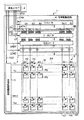
図2はデータレジスタ6の詳細な回路構成を示す。データレジスタ6は、この実施形態では、信号線X分のディジタル映像信号DATAが水平走査期間に順番にシリアルに入力されることから、信号線X1〜Xnに割り当てられるn個のラッチ回路9で構成される。サンプリング信号S1〜Snはこれらラッチ回路9にそれぞれ供給され、ラッチ信号LTはこれらラッチ回路9に共通に供給される。各ラッチ回路9は4ビットの映像信号DATAをビット単位にサンプリングするために4個のサンプリングラッチ10を含む。
【0018】
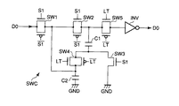
各サンプリングラッチ10は第1および第2容量素子C1,C2と、これら容量素子C1,C2を並列に接続してバス配線DBのビット線D0〜D3の対応する1本、例えばビット線D0からの信号電圧を容量素子C1,C2にそれぞれ保持させるサンプル状態およびこのサンプル状態に続いて容量素子C1,C2を直列に接続してレベル加算させた信号電圧を容量素子C1,C2から出力する出力状態を設定する接続制御回路SWCと、出力状態で容量素子C1,C2から出力される信号電圧により動作するインバータ回路INVを含む。ここでは、インバータ回路INVが1個のインバータで構成されるが、複数のインバータ回路を縦列に接続した構成であってもよい。
【0019】
接続制御回路SWCはサンプル信号S1からSnのうちの1つ、例えばサンプル信号S1により制御されサンプル状態で導通する第1から第3スイッチ素子SW1,SW2,SW3およびラッチ信号LTにより制御され出力状態で導通する第4および第5スイッチ素子SW4,SW5を含む。容量素子C2は一端においてスイッチ素子SW1を介してビット線D0に接続されると共に他端において基準電位端子GNDに接続される。容量素子C1は一端においてスイッチ素子SW1,SW2を介してビット線D0に接続されさらにスイッチ素子SW5を介してインバータ回路INVの入力端に接続されると共に、他端においてスイッチ素子SW3を介して基準電位端子GNDに接続されさらにスイッチ素子SW4を介して上述した容量素子C2の一端に接続される。
【0020】
次に、上述のサンプリングラッチ10の動作を説明する。例えばサンプル信号S1がシフトレジスタ5から出力されたとき、スイッチ素子SW1〜SW5が図2に示すサンプル状態となる。すなわち、スイッチ素子SW1〜SW3だけが導通し、バス配線DBのビット線D0からの信号電圧がスイッチSW1を介して容量素子C2の一端に印加されると共に、スイッチSW1およびSW2を介して容量素子C1の一端に印加される。このとき、スイッチSW3を容量素子C1の他端を基準電源端子GNDに接続するため、容量素子C1,C2は互いに並列な関係となる。ビット線D0からの信号電圧が3.3Vであるとすると、容量素子C1,C2はそれぞれ3.3Vまで電荷を蓄積する。スイッチ素子SW1〜SW3がサンプル信号S1の出力停止に伴って非導通となると、容量素子C1,C2が3.3Vの電圧を保持して電気的にフローティングされる。
【0021】
続いて、ラッチ信号LTが液晶コントローラ2から出力されると、スイッチ素子SW1〜SW5が図3に示す出力状態となる。すなわち、スイッチ素子SW4,SW5だけが導通し、容量素子C1,C2は互いに直列な関係となる。これにより、容量素子C1,C2にそれぞれ保持された3.3Vの信号電圧がレベル加算されてインバータ回路INVに出力される。
【0022】
ちなみに、信号電圧が0Vであった場合には、スイッチ素子SW1〜SW5がサンプル状態から出力状態に遷移しても、インバータ回路INVに入力される信号電圧は0Vのままとなる。また、容量素子C2の容量値を容量素子C1の容量値よりも大きくすれば、レベル加算の結果としてインバータ回路INVに入力される信号電圧をさらに高いレベルにシフトさせることが可能である。
【0023】
図4はスイッチ素子SW1〜SW5の構成例を示す。スイッチ素子SW1〜SW5はいずれも一対のPおよびNチャネル薄膜トランジスタで構成されるトランスファゲートで構成することができるが、ここではスイッチ素子SW1だけが基準電位の給電用であるため単一のNチャネル薄膜トランジスタで構成している。
【0024】
本実施形態では、表示装置がデジタル映像信号を受け取るバス配線DBと、バス配線DB上のデジタル映像信号DATAを順次サンプリングして並列的に出力するデータレジスタ6を少なくとも含む信号処理回路を備える。データレジスタ6はデジタル映像信号の信号電圧をそれぞれビット単位にレベル変換する複数のサンプリングラッチ10を含み、各サンプリングラッチ10の接続制御回路SWCが容量素子C1,C2を並列に接続してバス配線DBの対応ビット線からの信号電圧を容量素子C1,C2にそれぞれ保持させるサンプル状態およびこのサンプル状態に続いて容量素子C1,C2を直列に接続してレベル加算させた信号電圧を容量素子C1,C2から出力する出力状態を設定する。この場合、寄生容量の大きなバス配線DBをレベル変換のために駆動する必要がないため消費電力の増大を防止できる。また、データレジスタ6がレベル変換を兼ねてバス配線DB上の映像信号DATAを順次のサンプリングし並列的に出力するため回路規模の増大も防止できる。さらに、データレジスタ6からの出力用にインバータ回路INVを設けても、上述の構成ではインバータ回路INVが自身の閾値に近いレベルで入力する信号電圧のレベル変換を行なう必要がないため、閾値のばらつきによる影響を受けずに動作する。従って、信号処理回路の動作を安定化できる。
【0025】
尚、本発明は上述の実施形態に限定されず、その要旨を逸脱しない範囲で様々に変形可能である。
【0026】
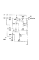
図2に示すサンプリングラッチ10は例えば図5に示すように変形してもよい。図5では、第3容量素子C3が設けられ、接続制御回路SWCがサンプル状態で導通する第6および第7スイッチ素子SW6,SW7、並びに出力状態で導通する第8スイッチ素子SW8をさらに含む。バス配線DBのビット線D0はスイッチ素子SW1,SW6および容量素子C3を介して基準電位端子GNDに接続され、容量素子C2の他端はスイッチ素子SW7を介して基準電位端子GNDに接続されさらにスイッチ素子SW8および容量素子C3を介して基準電位端子GNDに接続される。このように容量素子C3を追加した構成では、低電圧振幅の信号についても、レベルシフトすることが可能である。
【0027】
また、上述の実施形態では液晶表示装置について説明したが、本発明は有機EL表示装置等にも適用可能である。
【0028】
【発明の効果】
以上のように本発明によれば、低消費電力あるいは回路規模を増大させることなく安定に動作可能な信号処理回路およびこの信号処理回路を備えた表示装置を提供することができる。
【図面の簡単な説明】
【図1】本発明の一実施形態に係る液晶表示装置の概略的な構造を示す図である。
【図2】図1に示すデータレジスタの詳細な回路構成を示す図である。
【図3】図2に示す接続制御回路がサンプル状態から出力状態に遷移したときの動作を説明するための図である。
【図4】図2に示す第1から第5スイッチ素子の構成例を示す図である。
【図5】図2に示すサンプリングラッチの変形例を示す図である。
【符号の説明】
4…信号線駆動回路
6…データレジスタ
10…サンプリングラッチ
C1,C2…容量素子
DB…バス配線
SWC…接続制御回路
PX…表示画素
X…信号線[0001]
BACKGROUND OF THE INVENTION
The present invention relates to a signal processing circuit for sampling the digital video signal relates example, signal processing circuits for level conversion to a larger voltage amplitude while sampling the signal voltage of the digital video signal.
[0002]
[Prior art]
Active matrix liquid crystal display devices are light, thin and have low power consumption, and can display clear images with a resolution comparable to or higher than that of CRTs. Therefore, they are widely used as monitor displays for information equipment terminals and thin televisions. Yes. A typical active matrix liquid crystal display device includes a liquid crystal display panel that displays an image and a display control circuit that controls the operation of the liquid crystal display panel.
[0003]
The liquid crystal display panel includes a plurality of display pixels arranged in a matrix, a plurality of scanning lines arranged along the rows of the display pixels, a plurality of signal lines arranged along the columns of the display pixels, and these signals. A plurality of pixel switches are provided respectively near the intersections of the lines and the scanning lines. Each pixel switch is a thin film transistor using a semiconductor thin film such as amorphous silicon or polysilicon, and applies the potential of the corresponding signal line to the corresponding display pixel in response to the scanning signal from the corresponding scanning line. The display pixel has a structure in which a liquid crystal layer is sandwiched between a pixel electrode and a counter electrode, and the light transmittance of the liquid crystal layer is set by a signal line potential applied to the pixel electrode with respect to the counter electrode potential. The display control circuit is a scanning line driving circuit that sequentially supplies scanning signals to a plurality of scanning lines for each vertical scanning period, and a video signal is supplied to a plurality of signal lines for each horizontal scanning period in which the scanning signal is supplied to one scanning line. And a liquid crystal controller that controls operations of the scanning line driving circuit and the signal line driving circuit. The scanning line driving circuit and the signal line driving circuit are usually mounted on the end of the liquid crystal display panel as a driver IC chip.
[0004]
In recent years, instead of mounting the above-described driver IC chip, a scanning line driving circuit is used to reduce the manufacturing cost while relaxing the restrictions on the effective screen area depending on the area occupied by the connection terminal group with the external circuit of the liquid crystal display panel. Further, development of a liquid crystal display panel with a built-in drive circuit in which a signal line drive circuit is formed of, for example, a thin film transistor in the same manner as a pixel switch and is integrated with the liquid crystal display panel is progressing. The signal line driving circuit receives a digital video signal generated in series with respect to a plurality of signal lines from the liquid crystal controller and supplied to an external wiring terminal of the liquid crystal display panel, and a plurality of signals connected to the external wiring terminal via a bus wiring. The digital video signal is sequentially sampled using the sampling latch, and a plurality of signal lines are driven in parallel based on the sampling results.
[0005]
[Problems to be solved by the invention]
Incidentally, an external circuit such as a liquid crystal controller is generally constituted by an IC chip made of single crystal silicon and is driven with a voltage amplitude of about 3.3V. On the other hand, a signal line driving circuit composed of a thin film transistor using a semiconductor thin film such as polysilicon needs to be driven with a larger amplitude than that of an external circuit, for example, a voltage amplitude of about 5 V due to the problem of the threshold. . For this reason, it is necessary to convert the level of a digital video signal input with 3.3 V amplitude from an external circuit to 5 V amplitude.
Conventionally, various level conversion methods have been considered for this signal line driving circuit. When only a positive-phase digital video signal is supplied from the LCD controller to reduce the number of bus lines, for example, a level shifter using an inverter is inserted in the bus line near the external wiring terminal, and level conversion is performed by this level shifter. It is conceivable to distribute the digital video signal thus obtained to a plurality of sampling latches. However, in this method, the level shifter needs to shift the potential of the bus wiring having a large parasitic capacitance to near 5 V, which causes an increase in power consumption. When the voltage amplitude on the bus wiring is maintained at 3.3 V, for example, a plurality of inverters are arranged as level shifters between these sampling latches and the bus wiring. In this method, the signal line driver circuit may malfunction due to threshold variations that are difficult to avoid between these inverters. This malfunction can be prevented by adding a threshold cancel circuit in front of each inverter and preparing a reference voltage for the threshold cancel circuit, but this leads to an increase in circuit scale and power consumption.
[0006]
An object of the present invention is to provide a stable operation possible signal processing circuits without increasing the power consumption or circuit scale.
[0007]
[Means for Solving the Problems]
According to the present invention, a bus wiring for receiving a digital video signal and a data register for sequentially sampling and outputting the digital video signal on the bus wiring in parallel are provided. Each of the sampling latches includes a plurality of capacitor elements and a plurality of capacitor elements connected in parallel to each other to convert a signal voltage from a corresponding bit line of the bus wiring into a plurality of capacitor elements. signal processing including a connection control circuit for setting the output state of outputting a plurality of capacitive elements connected to the signal voltage obtained by level added to the series of a plurality of capacitive elements following the sampling state and the sample state is held respectively A circuit is provided.
[0009]
In this signal processing circuits, the sample state and the connection control circuit of each sampling latches to hold respectively a signal voltage from the corresponding bit line by connecting bus lines several capacitive elements in parallel to a plurality of capacitive elements Following sample state to set the output state of outputting a plurality of capacitive elements connected to the signal voltage obtained by level added to the series of a plurality of capacitive elements. In this case, since it is not necessary to drive a bus wiring having a large parasitic capacitance for level conversion, an increase in power consumption can be prevented. Further, since the data register also performs level conversion and sequentially samples the video signals on the bus wiring and outputs them in parallel, an increase in circuit scale can be prevented. Furthermore, even if an inverter circuit is provided for output from the data register, the above-described configuration does not require level conversion of the signal voltage input by the inverter circuit at a level close to its own threshold value. Works without receiving. Therefore, the operation of the signal processing circuit can be stabilized.
[0010]
DETAILED DESCRIPTION OF THE INVENTION
Hereinafter, a liquid crystal display device according to an embodiment of the present invention will be described with reference to the drawings.
[0011]
FIG. 1 shows a schematic structure of the liquid crystal display device. The liquid crystal display device includes a liquid
[0012]
The array substrate AR includes a plurality of pixel electrodes PE arranged in a matrix on a glass substrate, a plurality of scanning lines Y (Y1 to Ym) formed along a row of the plurality of pixel electrodes PE, and a plurality of pixel electrodes PE. A plurality of signal lines X (X1 to Xn), signal lines X1 to Xn, and scanning lines Y1 to Ym, which are formed along the column, are arranged adjacent to the intersections of the scanning lines Y1 to Ym. In response, the video signal voltage from the corresponding signal line X is captured and supplied to the corresponding pixel electrode PE, the pixel switch W, the scanning
[0013]
The liquid crystal controller 2 outputs, for example, a 4-bit digital video signal DATA (D0 to D3) together with various control signals synchronized with the video signal DATA. These control signals include a horizontal scanning control signal YCT such as a vertical start pulse and a vertical clock signal, and a horizontal scanning control signal such as a horizontal start pulse STH, a horizontal clock signal CKH, a latch signal LT, and a load signal LOAD. The vertical start pulse and the vertical clock signal are supplied to the scanning
[0014]
The horizontal start signal STH is a pulse generated every horizontal scanning period (1H), the horizontal clock signal CKH is a pulse generated by the number of signal lines in each horizontal scanning period, and the vertical start signal is one vertical scanning period. The vertical clock signal CHV is generated every number of scanning lines in each vertical scanning period, and the latch signal LT latches the sample result of the digital video signal DATA every horizontal scanning period. The load signal LOAD is a signal for permitting parallel driving of the plurality of signal lines X every horizontal scanning period. The liquid crystal controller 2 has a power supply circuit that generates the gradation reference voltage VREF. This gradation reference voltage VREF is supplied to the signal line drive circuit 4.
[0015]
The scanning
[0016]
The signal line drive circuit 4 includes a
[0017]
FIG. 2 shows a detailed circuit configuration of the
[0018]
Each
[0019]
The connection control circuit SWC is controlled by one of the sample signals S1 to Sn, for example, the first to third switch elements SW1, SW2, SW3, which are controlled by the sample signal S1 and conducted in the sample state, and the latch signal LT, and in the output state. It includes fourth and fifth switch elements SW4 and SW5 that are conductive. The capacitive element C2 is connected at one end to the bit line D0 via the switch element SW1 and at the other end to the reference potential terminal GND. The capacitive element C1 is connected at one end to the bit line D0 via the switch elements SW1 and SW2, and further connected to the input terminal of the inverter circuit INV via the switch element SW5, and at the other end to the reference potential via the switch element SW3. It is connected to the terminal GND and further connected to one end of the above-described capacitive element C2 via the switch element SW4.
[0020]
Next, the operation of the
[0021]
Subsequently, when the latch signal LT is output from the liquid crystal controller 2, the switch elements SW1 to SW5 are in the output state shown in FIG. That is, only the switch elements SW4 and SW5 are conducted, and the capacitive elements C1 and C2 are in series with each other. As a result, the level of the 3.3V signal voltage held in each of the capacitive elements C1 and C2 is added and output to the inverter circuit INV.
[0022]
Incidentally, when the signal voltage is 0V, the signal voltage input to the inverter circuit INV remains 0V even when the switch elements SW1 to SW5 transition from the sample state to the output state. Moreover, if larger than the capacitance of the capacitor C1 a capacitance of the capacitor C2, it is possible to shift more have high levels resulting signal voltage input to the inverter circuit INV level adder.
[0023]
FIG. 4 shows a configuration example of the switch elements SW1 to SW5. Each of the switch elements SW1 to SW5 can be composed of a transfer gate composed of a pair of P and N channel thin film transistors. However, since only the switch element SW1 is for supplying a reference potential, a single N channel thin film transistor is used here. It consists of.
[0024]
In this embodiment, the display device includes a signal processing circuit including at least a bus line DB that receives a digital video signal and a
[0025]
In addition, this invention is not limited to the above-mentioned embodiment, It can deform | transform variously in the range which does not deviate from the summary.
[0026]
The
[0027]
In the above-described embodiment, the liquid crystal display device has been described. However, the present invention can also be applied to an organic EL display device and the like.
[0028]
【The invention's effect】
As described above, according to the present invention, it is possible to provide a signal processing circuit that can operate stably without increasing power consumption or circuit scale, and a display device including the signal processing circuit.
[Brief description of the drawings]
FIG. 1 is a diagram showing a schematic structure of a liquid crystal display device according to an embodiment of the present invention.
FIG. 2 is a diagram showing a detailed circuit configuration of a data register shown in FIG. 1;
FIG. 3 is a diagram for explaining an operation when the connection control circuit shown in FIG. 2 transitions from a sample state to an output state;
4 is a diagram showing a configuration example of first to fifth switch elements shown in FIG. 2. FIG.
FIG. 5 is a view showing a modification of the sampling latch shown in FIG. 2;
[Explanation of symbols]
4 ... signal
Claims (8)
Priority Applications (1)
| Application Number | Priority Date | Filing Date | Title |
|---|---|---|---|
| JP2002027128A JP4047594B2 (en) | 2002-02-04 | 2002-02-04 | Signal processing circuit |
Applications Claiming Priority (1)
| Application Number | Priority Date | Filing Date | Title |
|---|---|---|---|
| JP2002027128A JP4047594B2 (en) | 2002-02-04 | 2002-02-04 | Signal processing circuit |
Publications (3)
| Publication Number | Publication Date |
|---|---|
| JP2003228341A JP2003228341A (en) | 2003-08-15 |
| JP2003228341A5 JP2003228341A5 (en) | 2005-08-18 |
| JP4047594B2 true JP4047594B2 (en) | 2008-02-13 |
Family
ID=27748748
Family Applications (1)
| Application Number | Title | Priority Date | Filing Date |
|---|---|---|---|
| JP2002027128A Expired - Fee Related JP4047594B2 (en) | 2002-02-04 | 2002-02-04 | Signal processing circuit |
Country Status (1)
| Country | Link |
|---|---|
| JP (1) | JP4047594B2 (en) |
Families Citing this family (4)
| Publication number | Priority date | Publication date | Assignee | Title |
|---|---|---|---|---|
| KR100732809B1 (en) * | 2005-11-03 | 2007-06-27 | 삼성에스디아이 주식회사 | Data Driver and Organic Light Emitting Display Using the same |
| KR100690434B1 (en) | 2006-01-02 | 2007-03-12 | 삼성전자주식회사 | Digital to analog converter, data line driver, and display device and method thereof |
| US10140940B2 (en) | 2015-07-24 | 2018-11-27 | Japan Display Inc. | Display device |
| JP6269799B2 (en) * | 2016-12-14 | 2018-01-31 | セイコーエプソン株式会社 | Electro-optical device and electronic apparatus |
Family Cites Families (3)
| Publication number | Priority date | Publication date | Assignee | Title |
|---|---|---|---|---|
| JP2844650B2 (en) * | 1989-01-21 | 1999-01-06 | 日本電気株式会社 | Switch capacitor output voltage control circuit |
| JP3619299B2 (en) * | 1995-09-29 | 2005-02-09 | パイオニア株式会社 | Light emitting element drive circuit |
| JP4576648B2 (en) * | 1998-12-21 | 2010-11-10 | ソニー株式会社 | Liquid crystal display |
-
2002
- 2002-02-04 JP JP2002027128A patent/JP4047594B2/en not_active Expired - Fee Related
Also Published As
| Publication number | Publication date |
|---|---|
| JP2003228341A (en) | 2003-08-15 |
Similar Documents
| Publication | Publication Date | Title |
|---|---|---|
| JP3501939B2 (en) | Active matrix type image display | |
| US7508479B2 (en) | Liquid crystal display | |
| US7088328B2 (en) | Liquid crystal display device having a circuit for controlling polarity of video signal for each pixel | |
| US8730223B2 (en) | Source driver and display device having the same | |
| JP4779853B2 (en) | Digital-analog converter and video display device | |
| JP4734514B2 (en) | System for providing drive voltage to display panel | |
| JP4407464B2 (en) | Electro-optical device and electronic apparatus | |
| KR20030094043A (en) | Display apparatus and portable terminal | |
| US7173593B2 (en) | Memory circuit, display circuit, and display device | |
| US7286071B1 (en) | System for displaying images | |
| US20120120040A1 (en) | Drive Device For Display Circuit, Display Device, And Electronic Apparatus | |
| KR20020061471A (en) | Image display apparatus and driving method thereof | |
| KR20040028573A (en) | Display device and driving method therefor | |
| WO2020194492A1 (en) | Display device | |
| KR100774895B1 (en) | Liquid crystal display device | |
| TW201935106A (en) | Display device without a driver IC | |
| US7505021B2 (en) | Capacitive load driving circuit and display panel driving circuit | |
| JP4047594B2 (en) | Signal processing circuit | |
| JP3675113B2 (en) | Display device | |
| JP4664466B2 (en) | Display device | |
| TW584825B (en) | Planar display device | |
| JP2001312255A (en) | Display device | |
| WO2020194493A1 (en) | Display device | |
| JP4474138B2 (en) | Pixel drive unit for display device, display circuit, and display device | |
| JP4230752B2 (en) | Driving method of liquid crystal display device |
Legal Events
| Date | Code | Title | Description |
|---|---|---|---|
| A521 | Written amendment |
Free format text: JAPANESE INTERMEDIATE CODE: A523 Effective date: 20050203 |
|
| A621 | Written request for application examination |
Free format text: JAPANESE INTERMEDIATE CODE: A621 Effective date: 20050203 |
|
| A977 | Report on retrieval |
Free format text: JAPANESE INTERMEDIATE CODE: A971007 Effective date: 20070312 |
|
| A711 | Notification of change in applicant |
Free format text: JAPANESE INTERMEDIATE CODE: A711 Effective date: 20070514 |
|
| A131 | Notification of reasons for refusal |
Free format text: JAPANESE INTERMEDIATE CODE: A131 Effective date: 20070626 |
|
| A521 | Written amendment |
Free format text: JAPANESE INTERMEDIATE CODE: A523 Effective date: 20070827 |
|
| TRDD | Decision of grant or rejection written | ||
| A01 | Written decision to grant a patent or to grant a registration (utility model) |
Free format text: JAPANESE INTERMEDIATE CODE: A01 Effective date: 20071120 |
|
| A61 | First payment of annual fees (during grant procedure) |
Free format text: JAPANESE INTERMEDIATE CODE: A61 Effective date: 20071122 |
|
| FPAY | Renewal fee payment (event date is renewal date of database) |
Free format text: PAYMENT UNTIL: 20101130 Year of fee payment: 3 |
|
| R150 | Certificate of patent or registration of utility model |
Ref document number: 4047594 Country of ref document: JP Free format text: JAPANESE INTERMEDIATE CODE: R150 Free format text: JAPANESE INTERMEDIATE CODE: R150 |
|
| S533 | Written request for registration of change of name |
Free format text: JAPANESE INTERMEDIATE CODE: R313533 |
|
| FPAY | Renewal fee payment (event date is renewal date of database) |
Free format text: PAYMENT UNTIL: 20101130 Year of fee payment: 3 |
|
| R350 | Written notification of registration of transfer |
Free format text: JAPANESE INTERMEDIATE CODE: R350 |
|
| FPAY | Renewal fee payment (event date is renewal date of database) |
Free format text: PAYMENT UNTIL: 20101130 Year of fee payment: 3 |
|
| FPAY | Renewal fee payment (event date is renewal date of database) |
Free format text: PAYMENT UNTIL: 20111130 Year of fee payment: 4 |
|
| FPAY | Renewal fee payment (event date is renewal date of database) |
Free format text: PAYMENT UNTIL: 20111130 Year of fee payment: 4 |
|
| FPAY | Renewal fee payment (event date is renewal date of database) |
Free format text: PAYMENT UNTIL: 20121130 Year of fee payment: 5 |
|
| S531 | Written request for registration of change of domicile |
Free format text: JAPANESE INTERMEDIATE CODE: R313531 |
|
| FPAY | Renewal fee payment (event date is renewal date of database) |
Free format text: PAYMENT UNTIL: 20121130 Year of fee payment: 5 |
|
| R350 | Written notification of registration of transfer |
Free format text: JAPANESE INTERMEDIATE CODE: R350 |
|
| S533 | Written request for registration of change of name |
Free format text: JAPANESE INTERMEDIATE CODE: R313533 |
|
| FPAY | Renewal fee payment (event date is renewal date of database) |
Free format text: PAYMENT UNTIL: 20121130 Year of fee payment: 5 |
|
| R350 | Written notification of registration of transfer |
Free format text: JAPANESE INTERMEDIATE CODE: R350 |
|
| FPAY | Renewal fee payment (event date is renewal date of database) |
Free format text: PAYMENT UNTIL: 20131130 Year of fee payment: 6 |
|
| R250 | Receipt of annual fees |
Free format text: JAPANESE INTERMEDIATE CODE: R250 |
|
| R250 | Receipt of annual fees |
Free format text: JAPANESE INTERMEDIATE CODE: R250 |
|
| R250 | Receipt of annual fees |
Free format text: JAPANESE INTERMEDIATE CODE: R250 |
|
| R250 | Receipt of annual fees |
Free format text: JAPANESE INTERMEDIATE CODE: R250 |
|
| R250 | Receipt of annual fees |
Free format text: JAPANESE INTERMEDIATE CODE: R250 |
|
| R250 | Receipt of annual fees |
Free format text: JAPANESE INTERMEDIATE CODE: R250 |
|
| LAPS | Cancellation because of no payment of annual fees |