JP4046880B2 - Air conditioning equipment for construction machinery - Google Patents
Air conditioning equipment for construction machinery Download PDFInfo
- Publication number
- JP4046880B2 JP4046880B2 JP37507898A JP37507898A JP4046880B2 JP 4046880 B2 JP4046880 B2 JP 4046880B2 JP 37507898 A JP37507898 A JP 37507898A JP 37507898 A JP37507898 A JP 37507898A JP 4046880 B2 JP4046880 B2 JP 4046880B2
- Authority
- JP
- Japan
- Prior art keywords
- outlet
- duct
- air
- damper
- foot
- Prior art date
- Legal status (The legal status is an assumption and is not a legal conclusion. Google has not performed a legal analysis and makes no representation as to the accuracy of the status listed.)
- Expired - Fee Related
Links
Images
Classifications
-
- B—PERFORMING OPERATIONS; TRANSPORTING
- B60—VEHICLES IN GENERAL
- B60H—ARRANGEMENTS OF HEATING, COOLING, VENTILATING OR OTHER AIR-TREATING DEVICES SPECIALLY ADAPTED FOR PASSENGER OR GOODS SPACES OF VEHICLES
- B60H1/00—Heating, cooling or ventilating devices
- B60H1/00642—Control systems or circuits; Control members or indication devices for heating, cooling or ventilating devices
- B60H1/00814—Control systems or circuits characterised by their output, for controlling particular components of the heating, cooling or ventilating installation
- B60H1/00821—Control systems or circuits characterised by their output, for controlling particular components of the heating, cooling or ventilating installation the components being ventilating, air admitting or air distributing devices
- B60H1/00835—Damper doors, e.g. position control
- B60H1/00842—Damper doors, e.g. position control the system comprising a plurality of damper doors; Air distribution between several outlets
-
- B—PERFORMING OPERATIONS; TRANSPORTING
- B60—VEHICLES IN GENERAL
- B60H—ARRANGEMENTS OF HEATING, COOLING, VENTILATING OR OTHER AIR-TREATING DEVICES SPECIALLY ADAPTED FOR PASSENGER OR GOODS SPACES OF VEHICLES
- B60H1/00—Heating, cooling or ventilating devices
- B60H1/00357—Air-conditioning arrangements specially adapted for particular vehicles
-
- B—PERFORMING OPERATIONS; TRANSPORTING
- B60—VEHICLES IN GENERAL
- B60H—ARRANGEMENTS OF HEATING, COOLING, VENTILATING OR OTHER AIR-TREATING DEVICES SPECIALLY ADAPTED FOR PASSENGER OR GOODS SPACES OF VEHICLES
- B60H1/00—Heating, cooling or ventilating devices
- B60H1/00421—Driving arrangements for parts of a vehicle air-conditioning
- B60H1/00435—Driving arrangements for parts of a vehicle air-conditioning fluid or pneumatic
-
- B—PERFORMING OPERATIONS; TRANSPORTING
- B60—VEHICLES IN GENERAL
- B60H—ARRANGEMENTS OF HEATING, COOLING, VENTILATING OR OTHER AIR-TREATING DEVICES SPECIALLY ADAPTED FOR PASSENGER OR GOODS SPACES OF VEHICLES
- B60H1/00—Heating, cooling or ventilating devices
- B60H1/00507—Details, e.g. mounting arrangements, desaeration devices
- B60H1/00557—Details of ducts or cables
- B60H1/00564—Details of ducts or cables of air ducts
Landscapes
- Physics & Mathematics (AREA)
- Thermal Sciences (AREA)
- Engineering & Computer Science (AREA)
- Mechanical Engineering (AREA)
- Air-Conditioning For Vehicles (AREA)
Description
【0001】
【発明の属する技術分野】
この発明は、例えば油圧ショベルなどの建設機械の空調装置に関するものである。
【0002】
【従来の技術】
車両用の空調装置は、例えば特開平7−25223号公報に開示されているように、冷房時に空調装置本体(以下、エアコンユニットという)で冷却された冷風を運転者の上半身に向けて吹出すためのフェイス吹出口や、暖房時にエアコンユニットで加温された温風を運転者の足元に向けて吹出すためのフット吹出口、また、フロントガラスに向けて吹出すことにより曇りを除去するためのデフ吹出口等を備えたダクトを設けて構成されている。
【0003】
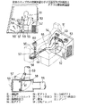
上記のような空調装置は、実開平3−49107号公報や実用新案公報第2544740号等に開示されているように、建設機械のキャブにも搭載されるようになってきている。この場合、オペレータが作業状況を見ながら作業レバーを操作する際の視界性や操作性を損なうことのないように、エアコン本体は運転席よりも後方に設置される。
【0004】
例えば上記実用新案公報第2544740号に記載のキャブでは、図5(a)(b)に示すように、運転席51の背後にエアコンユニット52が設置されており、このエアコンユニット52に、上端に後部吹出口53・53を有する二股状の後ダクト54が接続され、そして、この後ダクト54から分岐された前ダクト55が、キャブ内の右端側を床面に沿って前方に延びる形状で設けられている。この前ダクト55の前端に、フット吹出口56を備えた箱体57が分岐チャンバ58を介して接続され、また、この分岐チャンバ58の上面に、上方に延びる分岐ダクト59が接続されて、この分岐ダクト59の上端にフェイス吹出口60が形成されている。なお、フット吹出口56は、箱体57における運転席51側の面と前面とに各々形成されている
【0005】
分岐チャンバ58内には、同図(c)に示すように、板状のダンパ61が設けられている。このダンパ61を図中一点鎖線で示すように回動させることによって、分岐ダクト59への入口と箱体57への入口とを選択的に開口・閉止するようになっている。
【0006】
上記構成において、例えば冷房時には、同図(a)に示すように、後部吹出口53とフェイス吹出口60とからキャブ内における上方空間に向けて冷風の吹出しが行われる。一方、暖房時には、前記ダンパ61を切換作動させて、フット吹出口56から温風を吹出させ、これにより、オペレータの足元を暖めると共に、キャブにおけるフロントガラスの曇りを防止するようになっている。
【0007】
【発明が解決しようとする課題】
ところで、建設機械のキャブはその床面が泥土の付着によって汚れ易く、このため、床面に水を流して洗車し得る、いわゆるウオッシャブル化が図られようになってきている。この場合に、前記のような空調装置を搭載したキャブでは、洗車後に室内環境が悪化するという問題が生じている。つまり、上記のような空調装置はキャブの床面近くで開口するフット吹出口56を備えているため、洗車時にこのフット吹出口56を通してダクト内に泥水の侵入が生じ易い。そして、侵入した泥水がダクト内で乾燥すると、これが空調装置を作動させたときに土埃となって吹出口より噴出し、これによって、室内環境の悪化が生じている。
【0008】
この発明は、上記した問題点に鑑みなされたもので、その目的は、キャブの床面を洗車した後の作業環境の低下を抑制し得る建設機械の空調装置を提供することにある。
【0009】
【課題を解決するための手段および効果】
そこで請求項1の建設機械の空調装置は、空調装置本体3と、この空調装置本体3で加温又は冷却された空調空気をキャブ1前面側に導くダクト5とを備え、このダクト5にキャブ1の床面1a近くで開口する吹出口8を設けて成る建設機械の空調装置であって、上記吹出口8を開閉する開閉部材16と、エンジン停止時に上記吹出口8を閉止すべく開閉部材16の作動を制御する開閉制御手段とを設けていることを特徴としている。
【0010】
この構成によれば、床面1a近くで開口する吹出口8は、エンジン停止時に開閉部材16で閉止され、したがって、エンジン停止期間中に床面1aの洗車を行う際には、上記吹出口8は開閉部材16で閉止された状態となっているため、洗車時にダクト5内へ泥水が侵入することが防止される。この結果、ダクト内への泥水の侵入に起因する作業環境の低下が抑制される。
【0011】
しかも、上記のような吹出口8の閉止は、エンジンの停止に連動して自動的に行われ、オペレータが洗車時毎に吹出口8を手動で塞ぐような作業を必要としないので、作業性が向上する。また、このように手動で塞ぐ作業を前提とした場合、その作業がなされずに洗車が行われるおそれがあるが、上記のように自動的に吹出口8が閉止されることで、洗車時のダクト内への泥水の侵入がより確実に防止される。
【0012】
請求項2の建設機械の空調装置は、上記ダクト5内における上記吹出口8近傍領域にこの吹出口8の空調装置本体3への連通状態を変化させるダンパ16を設け、開閉制御手段がこのダンパ16を上記開閉部材としてエンジン停止時に上記吹出口8を内方から閉止する閉止位置に位置させるように制御することを特徴としている。
【0013】
この構成においては、吹出口8の空調装置本体3への連通状態を変化させるダンパ16で、エンジン停止期間中の吹出口8が閉止され、したがって、洗車時に吹出口8を塞ぐ専用の部材を別途設ける必要がないので、全体の構成をより簡素なものとすることができる。
【0014】
請求項3の建設機械の空調装置は、上記閉止位置に位置したときのダンパ16と上記吹出口8との間を囲う囲壁14の下面に、水抜き穴19を形成していることを特徴としている。
【0015】
すなわち、吹出口8からの空調空気の吹出方向に方向性を付与するためには、例えばダクトから吹出方向に突出する囲壁14を設け、この囲壁14の開口端に吹出グリルを取付る等の構成が採用される。このような場合に、上記囲壁14に水抜き穴19を形成しておくことで、洗車時に、吹出グリルとダンパ16による閉止位置との間に吹出グリルを通して侵入した水は、水抜き穴19を通して排出される。したがって、上記の部位にも泥水が滞留することが防止されるので、洗車時の泥水の侵入に起因する作業環境の低下をさらに抑制することができる。
【0018】
【発明の実施の形態】
次に、この発明の一実施形態について図面を参照しつつ詳細に説明する。
【0019】
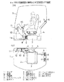
図2(a)に示すように、本実施形態に係る油圧ショベル等の建設機械のキャブ1内には、運転席2の下側に空調装置本体(以下、エアコンユニットという)3が設置されている。このエアコンユニット3には、図示しないクーラコアやヒータコアおよび送風ファン等が内装されている。そして、このエアコンユニット3に、キャブ1の背面に沿って上方に延びる後ダクト4と、後述する前ダクト5とが接続されている。後ダクト4の上端には、同図(b)に示すように、運転席2の後方で開口する一対の後部吹出口6・6が形成されている。
【0020】
前ダクト5は、キャブ1の右側(同図において上側)の側面に沿って前方に延びるように、エアコンユニット3の側面に接続された第1ダクト7と、フット吹出口8が形成された第2ダクト9と、フェイス吹出口10およびデフ吹出口11が形成された第3ダクト12(同図では二点鎖線で示している)とを順次接続して構成されている。
【0021】
フット吹出口8は、同図(a)に示すように、キャブ1の床面1a近くで開口するように、第2ダクト9の側面に設けられ、エアコンユニット3からの空調空気をオペレータの足元付近に吹出すように形成されている。一方、第3ダクト12は、第2ダクト9の前端から斜め前方に傾斜させた形状で設けられ、その前端のデフ吹出口11から、キャブ1の前窓に向かって空調空気が吹出されるように形成されている。また、この第3ダクト12には、その途中に斜め後方に延びる分岐ダクトが設けられて、その上端のフェイス吹出口10から、運転席2の上方領域、すなわち、オペレータの上半身に向けて、空調空気が吹出されるように構成されている。
【0022】
なお、上記キャブ1には、図示してはいないが、その前面に上記した前窓、背面に後窓がそれぞれ設けられており、また、同図におて紙面手前側の側面にスライド式のドアが、紙面奥側の側面に側窓がそれぞれ設けられている。また、運転席2の側部には、作業開始時にエンジンを始動させるためのイグニッションスイッチや、エアコンユニット3の運転スイッチ、さらに、後述する吹出モード設定スイッチ等が設けられたコントロールパネルが設置されている。このコントロールパネル内に、後述するダンパ16の切換制御を行うダンパ制御装置(開閉制御手段)等の各種制御装置が内装されている。
【0023】
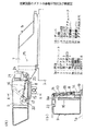
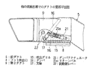
図3(a)には、前記フット吹出口8が設けられた第2ダクト9を上方から見た図を示している。この第2ダクト9は、同図(b)に示すように、断面略矩形状に形成され、前記キャブ1の室内側(図において右側)の垂直壁面9aに吹出開口13が形成されている。上記垂直壁面9aには、室内側に突出する突出囲壁14が、吹出開口13の外周を囲う形状で一体成形されている。この突出囲壁14の端面開口が上記フット吹出口8となっており、このフット吹出口8には、これを室内側から覆う吹出グリル15が取付けられている。
【0024】
一方、上記垂直壁面9aの内側にダンパ16が配置されている。このダンパ16は、平板状プレートの両面に耐候性・耐水性を有するエチレンプロピレンゴム(EPDM)等のシール材を張り付けて形成され、図のように、上記垂直壁面9aに平行でかつこれに密着する位置(以下、この位置をフェイス位置という)と、後述するように、上記垂直壁面9aから離間したフット位置との間で揺動自在に取付けられている。このダンパ16を図のようにフェイス位置に位置させることによって吹出開口13が閉じられ、これによって、フット吹出口8は、この吹出口8からの空調空気の吹出しが遮断された閉止状態となる。
【0025】
なお、吹出グリル15は、上記垂直壁面9aに近接する位置で、空調空気の吹出方向がやや上方に向かうように傾斜させて取付けられるように構成されている。このため、上記垂直壁面9aと吹出グリル15との間には、ダンパ16が上記のようにフェイス位置に位置するときも、吹出グリル15を通して室内側に連通する断面略三角形の空間(以下、出口空間という)18が形成される。この出口空間18を囲うように前記突出囲壁14が形成されており、この突出囲壁14の下面に、上下に貫通する水抜き穴19が形成されている。
【0026】
ダンパ16は、同図(a)に示すように、フット吹出口8よりもやや下流側(図において左側)の端部に設けられた支軸17によって、第2ダクト9内で上記支軸17回りに回動自在に取付けられている。支軸17は、第2ダクト9の上面を上方に貫通する形状で形成されている。一方、フット吹出口8よりも上流側における第2ダクト9の上面に、例えばサーボモータから成るダンパアクチュエータ21が取付けられており、このダンパアクチュエータ21の駆動軸に上記支軸17が、従動側レバー22・ロッド23・駆動側レバー24から成るリンク機構を介して接続されている。これにより、ダンパアクチュエータ21の作動に伴って、ダンパ16が、同図において破線で示す前記フェイス位置と、図中二点鎖線で示すように、第2ダクト9内で傾斜したフット位置との間で、支軸17回りに回動するように構成されている。
【0027】
前記したコントロールパネルには、図示してはいないが、フェイスモード・フットモード・フェイス/フットモードの3種の吹出モードのうちから、いずれかのモードを選択して設定するための吹出モード設定スイッチが設けられている。フェイスモードが設定されたときには、ダンパ16はダンパアクチュエータ21により上記したフェイス位置に回動されて定置される。
【0028】
これによって、フット吹出口8は前記したように閉止され、エアコンユニット3からの空調空気は、第2ダクト9を通して前記第3ダクト12へと供給される。この結果、この第3ダクト12に設けられている前記フェイス吹出口10とデフ吹出口11との両者を通して、空調空気が室内に吹出される。なお、これらフェイス吹出口10とデフ吹出口11とには、それぞれ吹出口を開閉する手動式のシャッタ部材が設けられており、これらシャッタ部材の操作により、フェイス吹出口10とデフ吹出口11とのいずれか一方を選択して空調空気の吹出しを行わせることが可能となっている。
【0029】
一方、フットモードに設定されたときには、ダンパ16は前記したフット位置に回動されて定置される。この位置では、フット吹出口8が開状態となり、第2ダクト9から前記第3ダクト12に至る流路がダンパ16によって閉止される。この結果、エアコンユニット3から第1ダクト7に供給される空調空気は、フット吹出口8のみを通して室内に、すなわち、前記したようにオペレータの足元付近に向けて吹出される。
【0030】
フェイス/フットモードにおいては、ダンパ16はフット位置とフェイス位置との間の中間位置に回動されて定置され、これにより、空調空気はフット吹出口8側と第3ダクト12とに分配されて、フット吹出口8と共に、前記フェイス吹出口10およびデフ吹出口11からも空調空気の室内への吹出しが行われるようになっている。
【0031】
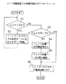
上記構成の空調装置を備えたキャブ1は、その床面1aに水を流して洗車し得る構造、例えば前記エアコンユニット3については、床面1aに流した水がこのエアユニット3内に侵入しないように、このエアユニット3が床面1aから所定の高さだけ離れて位置するように形成した取付架台を用いて、床面1a上に据付けられている。そして、床面1a近くの高さ位置で開口するフット吹出口8に対し、この吹出口8を通して洗車時の泥水が前ダクト5内に侵入しないように、エンジン停止時にフット吹出口8をダンパ16によって閉止状態とする制御が、前記ダンパ制御装置によって行われるようになっている。以下、このダンパ制御装置での具体的な制御手順について、図1を参照して説明する。
【0032】
まず、オペレータによってイグニッションキーが前記イグニッションスイッチに差し込まれ、エンジンONの操作が行われると、この操作過程で上記ダンパ制御装置による制御動作が開始され、ステップS1においてエンジンがONされたことが判別されると、ステップS2において、前記したコントロールパネルの吹出モード設定スイッチでの設定モードに合わせて、前記ダンパアクチュエータ21に駆動信号を出力し、その後、ステップS1に戻る処理を行う。
【0033】
これによって、ダンパ16が前記したフット位置やフェイス位置、或いは、これらの中間位置に定置され、エンジンのON状態が継続する間、これらの位置で保持される。また、この間に、例えばフットモードからフェイス/フットモードへの切換えが吹出モード設定スイッチで行われると、これに応じてダンパ16がフット位置から中間位置に移動される。
【0034】
暖房時には通常フットモードが選定される。これによって、エアコンユニット3で加温されて前ダクト5に供給される温風は、前記図2(a)(b)に示したように、フット吹出口8を通してオペレータの足元付近に向けて吹出される。なおこのとき、エアコンユニット3からの温風は、前記後ダクト4へも分配されて後部吹出口6からオペレータの背面に沿って上方にも吹出される。これにより、後窓を通しての放射冷却による背面側の温度低下が抑えられ、室内の暖房が好適に行われる。
【0035】
また、前窓に曇りが生じるような場合には、前記したフェイス/フットモードへの切換えを行うことで、温風がデフ吹出口11を通して前窓にも吹き付けられることになり、これによって、前窓の曇りが防止される。
【0036】
冷房時には、通常、デフ吹出口11を前記した手動式のシャッタ部材で閉止した状態で、フェイスモードが選定される。これによって、エアコンユニット3で冷却された冷風が後部吹出口6から上記同様に吹出され、また、フェイス吹出口10からオペレータの上半身に向けて吹出されて、室内冷房が行われる。
【0037】
このように室内の暖房または冷房下で所要の作業を行い、これを終了した後にオペレータが前記イグニッションキーによってエンジンを停止する操作を行うと、これが図1のステップS1で判別される。この時、このステップS1からS3に移行し、この時点での吹出設定モードがフェイスモードか否かを判別する。
【0038】
フェイスモードでないとき、すなわち、前記フットモード、或いはフェイス/フットモードのときには、ステップS4において、フェイス位置への切換信号を前記ダンパアクチュエータ21に出力し、これによって、ダンパ16をフェイス位置へと回動させる。そして、ステップS5においてダンパ16がフェイス位置に切換わったことが、例えばサーボモータから成る前記ダンパアクチュエータ21の動作信号によって確認されるまで待って、ステップS6においてコントロールパネルの電源回路をOFFにし、これによって前記ダンパ制御装置による制御動作が終了する。
【0039】
なお、前記ステップS3において、エンジンOFF時の設定モードがフェイスモードであることが判別されたときには、ダンパ16はすでにフェイス位置に位置していることから、このステップS3からS6に移行してコントロールパネルの電源回路をOFFにする処理を行い、制御動作を終了する。
【0040】
このような制御が行われることにより、エンジンOFFの期間は、ダンパ16は常時フェイス位置、すなわち、フット吹出口8を閉止した位置で保持される。この結果、エンジンを停止させて前記のように洗車する場合でも、フット吹出口8を通して前ダクト5内に泥水が侵入することが防止される。したがって、従来、洗車時にダクト内に侵入した泥水が乾燥し、これが空調装置を作動させたときに土埃となって吹出口より噴出するという不具合が生じていたが、本実施形態においては、これが防止されて快適な作業環境が維持される。
【0041】
しかも、フット吹出口8の閉止は、エンジンの停止に連動して自動的に行われるようになっており、オペレータが洗車時毎にフット吹出口8を手動で塞ぐような作業を必要としないので、作業性が向上する。また、このように手動で塞ぐ作業を前提とした場合には、その作業がなされずに洗車が行われるおそれがあるが、上記のように自動的にフット吹出口8を閉止する制御が行われることによって、洗車時のダクト内への泥水の侵入がより確実に防止される。
【0042】
また上記実施形態においては、フット吹出口8と、フェイス吹出口10およびデフ吹出口11との間で空調空気の吹出しを切換えるためのダンパ16によってフット吹出口8の開閉部材を構成しており、これによって、洗車時にフット吹出口8を塞ぐ専用の部材を別途設ける必要がないので、全体の構成もより簡素なものとなっている。
【0043】
さらに上記形態においては、フット吹出口8に取付けられた吹出グリル15と、ダンパ16による閉止位置との間に、前記した出口空間18が形成されており、洗車時には、吹出グリル15を通してこの出口空間18内に水の侵入が生じるが、この出口空間18を囲う前記突出囲壁14の下面に水抜き穴19が形成されているので、この出口空間18に侵入した水はこの水抜き穴19を通して排出される。したがって、この出口空間18の部位にも泥水が滞留することが防止されるので、エアコンユニット3の運転開始時に前記した土埃が吹出口を通して噴出するという不具合がさらに抑制される。
【0044】
なお上記実施形態においては、図3(a)に示すように、第1ダクト7の先端側の下面、すなわち、前ダクト5において最も高さの低い箇所に、ダクト内水抜き穴25が形成されている。これにより、フット吹出口8を通して前ダクト5内に洗車時の水が万一侵入したとしても、この水はダクト内水抜き穴25を通して下方に排出される。この結果、洗車時の泥水の侵入に起因する作業環境の低下をさらに確実に抑制し得るものとなっている。
【0045】
以上にこの発明の具体的な実施形態について説明したが、この発明は上記形態に限定されるものではなく、この発明の範囲内で種々変更することができる。例えば上記では、ダンパ16をフェイス位置とフット位置、およびこれらの間の中間位置との3位置に定置することが可能なように、サーボモータから成るダンパアクチュエータ21を設けて構成した例を示したが、例えば図4に示すように、シングルタイプの油圧シリンダ(或いはエアシリンダ)から成るダンパアクチュエータ21を設けて、フェイス位置とフット位置との2位置の切換えを行うような構成とすることも可能である。
【0046】
この場合、ダンパ16がフット位置(図中二点鎖線で示す位置)に位置しているときにエンジンが停止されると、このエンジンの停止に伴ってシリンダへの圧油(或いはエア)の供給も停止され、これに伴い、シリンダに内蔵されているリターンバネ21aによって、ダンパ16にフット位置からフェイス位置への切換わりが生じる。この結果、前記同様に、洗車時の泥水の侵入が防止されて作業環境の低下が抑制される。なお、この場合には、エンジン停止時にフット吹出口8を閉止するようにダンパ16の作動を制御する開閉制御手段としての機能を、上記ダンパアクチュエータ21が兼備した構成となる。
【0047】
一方、上記実施形態においては、フット吹出口8を第2ダクト9の垂直壁面9a近くに形成し、フェイスモードとフットモードとの吹出モードの切換えを行うための第2ダクト9内の切換ダンパ16に、エンジン停止時にフット吹出口8を閉止する開閉部材としての機能を兼用させたが、例えば上記ダンパ16による切換領域から離れた箇所にフット吹出口8を設け、上記切換領域からフット吹出口8との間を繋ぐダクト内に、フット吹出口8を通して吹出される吹出風量を調整するためのダンパ部材を設けるような場合には、このダンパ部材を、エンジン停止時にフット吹出口8を閉止する開閉部材として構成することが可能である。
【0048】
さらに、上記のようなダンパ部材や上記実施形態での切換ダンパ16とは別に、エンジン停止時にフット吹出口8を閉止するための専用のシャッタ部材を設けて、上記開閉部材として構成しても良い。
【0049】
また上記実施形態では、床面1a近くで開口する吹出口としてフット吹出口8を例に挙げたが、キャブの床面1a近くに設けられる吹出口であればフット吹出口8に限定されるものではなく、例えば前記デフ吹出口11がキャブ1の床面1a近くに設けられる場合には、この吹出口11に対しても上記同様の構成とすることが可能である。
【0050】
また上記実施形態では、エンジン停止時にダンパ16でフット吹出口8を閉止する構成に加え、さらに前ダクト5にダクト内水抜き穴25を設けた例を示したが、この水抜き穴25は必ずしも設ける必要はない。一方、エンジン停止時にフット吹出口8を閉止する構成とすることなく、フット吹出口8付近のダクト内に、上記のようなダクト内水抜き穴を複数設けただけの構成とすることも可能である。このような構成においても、洗車時に吹出口8を通してダクト内に侵入した泥水は、上記ダクト内水抜き穴を通して排出されるので、泥水の侵入に起因する作業環境の低下を抑制することができる。
【0051】
さらに上記では、建設機械として油圧ショベルを例に挙げて説明したが、その他の建設機械のキャブに搭載される空調装置に本発明を適用して構成することが可能である。
【図面の簡単な説明】
【図1】この発明の一実施形態における建設機械の空調装置に設けられたダンパ制御装置での制御手順を示すフローチャートである。
【図2】上記建設機械のキャブ内における空調装置の構成を示すもので、同図(a)は正面図、同図(b)は平面図である。
【図3】上記空調装置における第2ダクトの構成を示すもので、同図(a)は平面図、同図(b)は同図(a)におけるX−X線矢視断面図である。
【図4】この発明の他の実施形態における第2ダクトの要部平面図である。
【図5】従来の空調装置を備えた建設機械のキャブを示すもので、同図(a)はキュブの正面図、同図(b)は空調装置の構成を示す斜視図、同図(b)はダクトの要部断面図である。
【符号の説明】
1 キャブ
1a 床面
3 エアコンユニット(空調装置本体)
5 前ダクト
8 フット吹出口
14 突出囲壁
16 ダンパ(開閉部材)
19 水抜き穴
25 ダクト内水抜き穴[0001]
BACKGROUND OF THE INVENTION
The present invention relates to an air conditioner for a construction machine such as a hydraulic excavator.
[0002]
[Prior art]
As disclosed in, for example, Japanese Patent Application Laid-Open No. 7-25223, a vehicle air conditioner blows out cool air cooled by an air conditioner body (hereinafter referred to as an air conditioner unit) toward the driver's upper body during cooling. To remove the fog by blowing out the face air outlet, the foot air outlet for blowing warm air heated by the air conditioner unit toward the driver's feet during heating, and the windshield A duct having a differential outlet is provided.
[0003]
The air conditioner as described above is also mounted on a cab of a construction machine as disclosed in Japanese Utility Model Publication No. Hei 3-49107, Utility Model Publication No. 2544740, and the like. In this case, the air conditioner body is installed behind the driver's seat so as not to impair visibility and operability when the operator operates the work lever while watching the work situation.
[0004]
For example, in the cab described in the above Utility Model Publication No. 2544740, as shown in FIGS. 5 (a) and 5 (b), an
A plate-
[0006]
In the above configuration, for example, at the time of cooling, cold air is blown out from the
[0007]
[Problems to be solved by the invention]
By the way, the floor of the cab of a construction machine is likely to become dirty due to adhesion of mud, so that a so-called washable structure in which water can be washed by washing the floor with water has come to be achieved. In this case, in the cab equipped with the air conditioner as described above, there is a problem that the indoor environment deteriorates after the car is washed. That is, since the air conditioner as described above includes the
[0008]
The present invention has been made in view of the above-described problems, and an object of the present invention is to provide an air conditioner for a construction machine that can suppress a decrease in working environment after washing the cab floor.
[0009]
[Means for solving the problems and effects]
Therefore, the air conditioner for a construction machine according to
[0010]
According to this configuration, the
[0011]
Moreover, the closing of the
[0012]
The air conditioner for a construction machine according to
[0013]
In this configuration, the
[0014]
The air conditioner for a construction machine according to
[0015]
That is, in order to give directionality in the blowing direction of the conditioned air from the
[0018]
DETAILED DESCRIPTION OF THE INVENTION
Next, an embodiment of the present invention will be described in detail with reference to the drawings.
[0019]
As shown in FIG. 2A, an air conditioner main body (hereinafter referred to as an air conditioner unit) 3 is installed below the driver's
[0020]
The
[0021]
The
[0022]
Although not shown in the drawing, the
[0023]
FIG. 3A shows a view of the
[0024]
On the other hand, a
[0025]
In addition, the blowing
[0026]
As shown in FIG. 6A, the
[0027]
Although not shown in the above-mentioned control panel, a blowing mode setting switch for selecting and setting one of the three blowing modes of face mode / foot mode / face / foot mode Is provided. When the face mode is set, the
[0028]
As a result, the
[0029]
On the other hand, when the foot mode is set, the
[0030]
In the face / foot mode, the
[0031]
The
[0032]
First, when the ignition key is inserted into the ignition switch by the operator and the engine is turned on, the control operation by the damper control device is started in this operation process, and it is determined in step S1 that the engine is turned on. Then, in step S2, a drive signal is output to the
[0033]
As a result, the
[0034]
The normal foot mode is selected during heating. As a result, the warm air heated by the
[0035]
In addition, when the front window is cloudy, warm air is blown to the front window through the
[0036]
During cooling, the face mode is normally selected with the
[0037]
In this way, when the required work is performed under indoor heating or cooling, and the operator performs an operation to stop the engine with the ignition key after the completion of the work, this is determined in step S1 of FIG. At this time, the process proceeds from step S1 to S3, and it is determined whether or not the blowing setting mode at this time is the face mode.
[0038]
When the mode is not the face mode, that is, when the foot mode or the face / foot mode is selected, in step S4, a signal for switching to the face position is output to the
[0039]
When it is determined in step S3 that the setting mode when the engine is OFF is the face mode, the
[0040]
By performing such control, during the engine OFF period, the
[0041]
Moreover, the
[0042]
Moreover, in the said embodiment, the opening-and-closing member of the
[0043]
Further, in the above embodiment, the
[0044]
In the above embodiment, as shown in FIG. 3A, the
[0045]
Although specific embodiments of the present invention have been described above, the present invention is not limited to the above embodiments, and various modifications can be made within the scope of the present invention. For example, in the above description, an example in which the
[0046]
In this case, when the engine is stopped when the
[0047]
On the other hand, in the above embodiment, the
[0048]
In addition to the damper member as described above and the switching
[0049]
Moreover, in the said embodiment, although the
[0050]
Moreover, in the said embodiment, in addition to the structure which closes the
[0051]
Furthermore, in the above description, a hydraulic excavator has been described as an example of a construction machine. However, the present invention can be applied to an air conditioner mounted on a cab of another construction machine.
[Brief description of the drawings]
FIG. 1 is a flowchart showing a control procedure in a damper control device provided in an air conditioner for a construction machine according to an embodiment of the present invention.
FIGS. 2A and 2B show a configuration of an air conditioner in a cab of the construction machine. FIG. 2A is a front view and FIG. 2B is a plan view.
3A and 3B show a configuration of a second duct in the air conditioner, wherein FIG. 3A is a plan view, and FIG. 3B is a cross-sectional view taken along line XX in FIG.
FIG. 4 is a plan view of a main part of a second duct according to another embodiment of the present invention.
5A and 5B show a cab of a construction machine equipped with a conventional air conditioner. FIG. 5A is a front view of the cuvette, FIG. 5B is a perspective view showing the configuration of the air conditioner, and FIG. ) Is a sectional view of the main part of the duct.
[Explanation of symbols]
1
5
19
Claims (3)
Priority Applications (2)
| Application Number | Priority Date | Filing Date | Title |
|---|---|---|---|
| JP37507898A JP4046880B2 (en) | 1998-12-10 | 1998-12-10 | Air conditioning equipment for construction machinery |
| KR1019990056064A KR100685680B1 (en) | 1998-12-10 | 1999-12-09 | Air Conditioning Equipment of Construction Machinery |
Applications Claiming Priority (1)
| Application Number | Priority Date | Filing Date | Title |
|---|---|---|---|
| JP37507898A JP4046880B2 (en) | 1998-12-10 | 1998-12-10 | Air conditioning equipment for construction machinery |
Publications (2)
| Publication Number | Publication Date |
|---|---|
| JP2000168342A JP2000168342A (en) | 2000-06-20 |
| JP4046880B2 true JP4046880B2 (en) | 2008-02-13 |
Family
ID=18504930
Family Applications (1)
| Application Number | Title | Priority Date | Filing Date |
|---|---|---|---|
| JP37507898A Expired - Fee Related JP4046880B2 (en) | 1998-12-10 | 1998-12-10 | Air conditioning equipment for construction machinery |
Country Status (2)
| Country | Link |
|---|---|
| JP (1) | JP4046880B2 (en) |
| KR (1) | KR100685680B1 (en) |
Families Citing this family (5)
| Publication number | Priority date | Publication date | Assignee | Title |
|---|---|---|---|---|
| JP4824416B2 (en) * | 2006-01-30 | 2011-11-30 | 株式会社小松製作所 | Air conditioner |
| BRPI0800275B1 (en) * | 2008-01-18 | 2019-09-24 | Valeo Sistemas Automotivos Ltda | SINGLE GATE FOR CLOSING CENTRAL AND SIDE AIR OUTLETS IN AN AUTOMOTIVE VEHICLE CLIMATE HABIT |
| JP5538575B1 (en) | 2013-01-18 | 2014-07-02 | 株式会社小松製作所 | Controller assembly, work machine cab and work machine |
| KR102292746B1 (en) | 2015-02-10 | 2021-08-23 | 두산인프라코어 주식회사 | New air inlet for air conditioning unit |
| CN109532391A (en) * | 2018-12-13 | 2019-03-29 | 博耐尔汽车电气系统有限公司 | A kind of repositioning method of air conditioning HVAC damper positions |
Family Cites Families (3)
| Publication number | Priority date | Publication date | Assignee | Title |
|---|---|---|---|---|
| JPH0349107A (en) * | 1989-07-15 | 1991-03-01 | Nippon Chemicon Corp | Conducting paste for aluminum nitride sintered body |
| JPH0725223A (en) * | 1993-07-08 | 1995-01-27 | Nippondenso Co Ltd | Air conditioner for vehicle |
| KR970026095A (en) * | 1995-11-30 | 1997-06-24 | 김태구 | Drain hose for automotive air conditioner |
-
1998
- 1998-12-10 JP JP37507898A patent/JP4046880B2/en not_active Expired - Fee Related
-
1999
- 1999-12-09 KR KR1019990056064A patent/KR100685680B1/en not_active Expired - Fee Related
Also Published As
| Publication number | Publication date |
|---|---|
| KR100685680B1 (en) | 2007-02-23 |
| KR20000048026A (en) | 2000-07-25 |
| JP2000168342A (en) | 2000-06-20 |
Similar Documents
| Publication | Publication Date | Title |
|---|---|---|
| JP4261962B2 (en) | Hydraulic excavator air conditioner | |
| JP3976246B2 (en) | Air conditioner in construction machinery | |
| JP4046880B2 (en) | Air conditioning equipment for construction machinery | |
| KR101097612B1 (en) | Console air conditioner for vehicle | |
| JP3533932B2 (en) | Vehicle air conditioner | |
| JP4184549B2 (en) | Air conditioning equipment for construction machinery | |
| JP4909960B2 (en) | Hydraulic excavator air conditioner | |
| JP2530809Y2 (en) | Air conditioning equipment for construction vehicles | |
| JP2544740Y2 (en) | Duct structure of air conditioner for construction vehicles | |
| JP2561547Y2 (en) | Heater mounting structure in backhoe | |
| JP2008007055A (en) | Cabin air conditioner | |
| JP2008007055A5 (en) | ||
| JP2002275941A (en) | Air conditioning apparatus for construction machine | |
| JP2507378Y2 (en) | Vehicle air conditioner | |
| JP2000264036A (en) | Air conditioner for vehicles | |
| JP4292336B2 (en) | Cabin air conditioner | |
| JP4337182B2 (en) | Air conditioner for vehicles | |
| JP2533192Y2 (en) | Duct structure of air conditioner for construction vehicles | |
| JPH05462Y2 (en) | ||
| JP3798897B2 (en) | Air conditioner for automobile | |
| JP3603043B2 (en) | Arrangement structure of the duct of the air conditioner in the cab | |
| JPH10129237A (en) | Traveling work vehicle equipped with air conditioning unit | |
| JPH09286227A (en) | Air conditioner | |
| KR20250091922A (en) | Air conditioner for vehicle | |
| JP3565030B2 (en) | Defroster device |
Legal Events
| Date | Code | Title | Description |
|---|---|---|---|
| A621 | Written request for application examination |
Free format text: JAPANESE INTERMEDIATE CODE: A621 Effective date: 20050216 |
|
| A977 | Report on retrieval |
Free format text: JAPANESE INTERMEDIATE CODE: A971007 Effective date: 20070723 |
|
| A131 | Notification of reasons for refusal |
Free format text: JAPANESE INTERMEDIATE CODE: A131 Effective date: 20070731 |
|
| A521 | Written amendment |
Free format text: JAPANESE INTERMEDIATE CODE: A523 Effective date: 20070914 |
|
| TRDD | Decision of grant or rejection written | ||
| A01 | Written decision to grant a patent or to grant a registration (utility model) |
Free format text: JAPANESE INTERMEDIATE CODE: A01 Effective date: 20071113 |
|
| A61 | First payment of annual fees (during grant procedure) |
Free format text: JAPANESE INTERMEDIATE CODE: A61 Effective date: 20071121 |
|
| FPAY | Renewal fee payment (event date is renewal date of database) |
Free format text: PAYMENT UNTIL: 20101130 Year of fee payment: 3 |
|
| R150 | Certificate of patent or registration of utility model |
Free format text: JAPANESE INTERMEDIATE CODE: R150 |
|
| FPAY | Renewal fee payment (event date is renewal date of database) |
Free format text: PAYMENT UNTIL: 20101130 Year of fee payment: 3 |
|
| FPAY | Renewal fee payment (event date is renewal date of database) |
Free format text: PAYMENT UNTIL: 20111130 Year of fee payment: 4 |
|
| FPAY | Renewal fee payment (event date is renewal date of database) |
Free format text: PAYMENT UNTIL: 20111130 Year of fee payment: 4 |
|
| FPAY | Renewal fee payment (event date is renewal date of database) |
Free format text: PAYMENT UNTIL: 20121130 Year of fee payment: 5 |
|
| FPAY | Renewal fee payment (event date is renewal date of database) |
Free format text: PAYMENT UNTIL: 20131130 Year of fee payment: 6 |
|
| LAPS | Cancellation because of no payment of annual fees |