JP4044281B2 - Banknote handling equipment - Google Patents
Banknote handling equipment Download PDFInfo
- Publication number
- JP4044281B2 JP4044281B2 JP2000388961A JP2000388961A JP4044281B2 JP 4044281 B2 JP4044281 B2 JP 4044281B2 JP 2000388961 A JP2000388961 A JP 2000388961A JP 2000388961 A JP2000388961 A JP 2000388961A JP 4044281 B2 JP4044281 B2 JP 4044281B2
- Authority
- JP
- Japan
- Prior art keywords
- storage
- banknotes
- banknote
- control unit
- handling device
- Prior art date
- Legal status (The legal status is an assumption and is not a legal conclusion. Google has not performed a legal analysis and makes no representation as to the accuracy of the status listed.)
- Expired - Fee Related
Links
Images


Classifications
-
- G—PHYSICS
- G07—CHECKING-DEVICES
- G07F—COIN-FREED OR LIKE APPARATUS
- G07F19/00—Complete banking systems; Coded card-freed arrangements adapted for dispensing or receiving monies or the like and posting such transactions to existing accounts, e.g. automatic teller machines
-
- B—PERFORMING OPERATIONS; TRANSPORTING
- B65—CONVEYING; PACKING; STORING; HANDLING THIN OR FILAMENTARY MATERIAL
- B65H—HANDLING THIN OR FILAMENTARY MATERIAL, e.g. SHEETS, WEBS, CABLES
- B65H1/00—Supports or magazines for piles from which articles are to be separated
- B65H1/02—Supports or magazines for piles from which articles are to be separated adapted to support articles on edge
- B65H1/025—Supports or magazines for piles from which articles are to be separated adapted to support articles on edge with controlled positively-acting mechanical devices for advancing the pile to present the articles to the separating device
-
- G—PHYSICS
- G07—CHECKING-DEVICES
- G07D—HANDLING OF COINS OR VALUABLE PAPERS, e.g. TESTING, SORTING BY DENOMINATIONS, COUNTING, DISPENSING, CHANGING OR DEPOSITING
- G07D11/00—Devices accepting coins; Devices accepting, dispensing, sorting or counting valuable papers
- G07D11/10—Mechanical details
- G07D11/12—Containers for valuable papers
- G07D11/13—Containers for valuable papers with internal means for handling valuable papers
-
- G—PHYSICS
- G07—CHECKING-DEVICES
- G07D—HANDLING OF COINS OR VALUABLE PAPERS, e.g. TESTING, SORTING BY DENOMINATIONS, COUNTING, DISPENSING, CHANGING OR DEPOSITING
- G07D11/00—Devices accepting coins; Devices accepting, dispensing, sorting or counting valuable papers
- G07D11/20—Controlling or monitoring the operation of devices; Data handling
- G07D11/22—Means for sensing or detection
- G07D11/23—Means for sensing or detection for sensing the quantity of valuable papers in containers
-
- G—PHYSICS
- G07—CHECKING-DEVICES
- G07D—HANDLING OF COINS OR VALUABLE PAPERS, e.g. TESTING, SORTING BY DENOMINATIONS, COUNTING, DISPENSING, CHANGING OR DEPOSITING
- G07D11/00—Devices accepting coins; Devices accepting, dispensing, sorting or counting valuable papers
- G07D11/20—Controlling or monitoring the operation of devices; Data handling
- G07D11/22—Means for sensing or detection
- G07D11/235—Means for sensing or detection for monitoring or indicating operating conditions; for detecting malfunctions
-
- G—PHYSICS
- G07—CHECKING-DEVICES
- G07D—HANDLING OF COINS OR VALUABLE PAPERS, e.g. TESTING, SORTING BY DENOMINATIONS, COUNTING, DISPENSING, CHANGING OR DEPOSITING
- G07D11/00—Devices accepting coins; Devices accepting, dispensing, sorting or counting valuable papers
- G07D11/20—Controlling or monitoring the operation of devices; Data handling
- G07D11/24—Managing the stock of valuable papers
-
- B—PERFORMING OPERATIONS; TRANSPORTING
- B65—CONVEYING; PACKING; STORING; HANDLING THIN OR FILAMENTARY MATERIAL
- B65H—HANDLING THIN OR FILAMENTARY MATERIAL, e.g. SHEETS, WEBS, CABLES
- B65H2511/00—Dimensions; Position; Numbers; Identification; Occurrences
- B65H2511/10—Size; Dimensions
- B65H2511/15—Height, e.g. of stack
-
- B—PERFORMING OPERATIONS; TRANSPORTING
- B65—CONVEYING; PACKING; STORING; HANDLING THIN OR FILAMENTARY MATERIAL
- B65H—HANDLING THIN OR FILAMENTARY MATERIAL, e.g. SHEETS, WEBS, CABLES
- B65H2511/00—Dimensions; Position; Numbers; Identification; Occurrences
- B65H2511/20—Location in space
-
- B—PERFORMING OPERATIONS; TRANSPORTING
- B65—CONVEYING; PACKING; STORING; HANDLING THIN OR FILAMENTARY MATERIAL
- B65H—HANDLING THIN OR FILAMENTARY MATERIAL, e.g. SHEETS, WEBS, CABLES
- B65H2511/00—Dimensions; Position; Numbers; Identification; Occurrences
- B65H2511/30—Numbers, e.g. of windings or rotations
-
- B—PERFORMING OPERATIONS; TRANSPORTING
- B65—CONVEYING; PACKING; STORING; HANDLING THIN OR FILAMENTARY MATERIAL
- B65H—HANDLING THIN OR FILAMENTARY MATERIAL, e.g. SHEETS, WEBS, CABLES
- B65H2701/00—Handled material; Storage means
- B65H2701/10—Handled articles or webs
- B65H2701/19—Specific article or web
- B65H2701/1912—Banknotes, bills and cheques or the like
Landscapes
- Physics & Mathematics (AREA)
- General Physics & Mathematics (AREA)
- Engineering & Computer Science (AREA)
- Mechanical Engineering (AREA)
- Business, Economics & Management (AREA)
- Accounting & Taxation (AREA)
- Finance (AREA)
- Pile Receivers (AREA)
- Financial Or Insurance-Related Operations Such As Payment And Settlement (AREA)
Description
【0001】
【発明の属する技術分野】
本発明は紙幣取り扱い装置にかかり、特に紙幣収納庫を着脱して運用することのできる紙幣取り扱い装置に関する。
【0002】
【従来の技術】
特開平11−175801号公報には、入出金口、搬送路、紙幣判別部、一時保管庫および紙幣収納庫を備えた紙幣取り扱い装置が示されている。また、該紙幣取り扱い装置における紙幣収納庫は、入金庫、出金庫、リサイクル庫、装填・回収庫等で構成され、これらで構成する前記紙幣収納庫は紙幣取り扱い装置に対して着脱自在に取り付けることが示されている。
【0003】
【発明が解決しようとする課題】
前記従来の紙幣取り扱い装置においては、紙幣収納庫を紙幣取り扱い装置に対して着脱した場合、前記紙幣取り扱い装置は、自身に装着した収納庫内に存在する紙幣の枚数情報を取得することができない。このため、係員が紙幣を充填して収納庫が満杯になっているにもかかわらず、取引再開後に入金取引を実行して満杯の収納庫にさらに紙幣を収納しようとして異常を発生することがある。また、係員が紙幣を回収して収納庫が空になっているにもかかわらず、取引再開後に出金取引を実行して空の収納庫から紙幣を抽出しようとして異常を発生することがある。
【0004】
また、紙幣収納庫を紙幣取り扱い装置に対して着脱した場合、前記紙幣取り扱い装置は、自身に装着した収納庫の収納した金種(万円札、千円札など)あるいは収納庫のタイプ(入金庫,出金庫,リサイクル庫など)に関する情報を取得することができない。このため、異なる金種の収納庫が装着されたにもかかわらず、該収納庫から異なる紙幣を抽出しようとしたり、異なる紙幣を収納しようとしたり、あるいは出金専用の収納庫に紙幣を収納しようとしたり、入金専用の収納庫から紙幣を抽出しようとして異常を発生することがある。
【0005】
本発明は前記問題点に鑑みてなされたもので、装着した収納庫にかかる情報を取得し、係員に連絡することができる紙幣取り扱い装置を提供する。
【0006】
【課題を解決するための手段】
本発明は、上記の課題を解決するために次のような手段を採用した。
【0007】
紙幣を取り扱う紙幣取扱装置において、紙幣を入出金する入出金部と、前記紙幣取扱装置に着脱可能であって、前記入出金部から入金される紙幣又は前記入出金部から出金する紙幣を収納する複数の収納庫と、前記収納庫の着脱を検出するセンサと、前記センサの検出結果に対応して、前記収納庫が前記紙幣取扱装置から取り外されているという情報を記憶する記憶部と、前記入出金部と前記複数の収納庫とを接続し、紙幣を搬送する搬送路と、制御部とを具備し、前記複数の収納庫は、該収納庫内に収納された紙幣を押圧する押板を有し、前記制御部は、前記記憶部に前記収納庫が前記紙幣取扱装置から取り外されているという情報を記憶している場合に、前記センサが、該収納庫が前記紙幣取扱装置に装着されていることを検出すると、該収納庫が装着されていることに応じて該装着された収納庫内の前記押板を駆動して該収納庫に収納されている紙幣の紙幣量を検出する。
【0008】
【発明の実施の形態】
以下に本発明の実施形態を図1ないし図10を用いて説明する。図1は本発明の実施形態にかかる紙幣取り扱い装置を示す図、図2は紙幣取り扱い装置の制御ブロックを示す図である。これらの図において、1は入出金部、2は紙幣を紙幣取り扱い装置内の各所に搬送する紙幣の搬送路、3は紙幣の真偽、金種等を判別し、紙幣を出金に適する紙幣(正券)および出金に適さない紙幣(リジェクト券)を判別する紙幣判別部、4は巻き取り式の紙幣一時保管庫、5は紙幣収納庫、6は紙幣収納庫5内に装着したで押板であり、電動機等により駆動して紙幣を押圧しまた、押圧を解除する。押板6は押板6の位置を検出する押板位置カウンタを備え、該カウンタの計数値により押板位置(押圧したときは紙幣枚数)を検出することができる。7は紙幣の搬送路中に配置した通過センサであり、紙幣の通過を検出する。8は紙幣の搬送方向を切り換えるゲート、9は前記リジェクト券と判定した紙幣を収納するリジェクト券収納庫、10は紙幣取り扱い装置の筐体、10aは筐体10に形成した紙幣収納庫の装着部、11は筐体10の扉、12は扉11の開閉を検出する開閉検出センサ、13は収納庫が装着位置にあるか否かを検出する収納庫定位置検出センサ、14は押圧検出センサ、15は収納庫内の紙幣が空であることを検出する空検出センサ、16、17は押板6を検出して、後述する押板位置カウンタを更正する押板センサであり、センサ17は紙幣の満杯位置にある押板を検出し、センサ16は紙幣の残量少位置にある押板を検出する。なお、前記押板位置カウンタは押板の位置を検出し、この検出位置に基づいて紙幣枚数を検出することができる。18は入出金部の入り口に設けたシャッタ、19は入出金を押圧保持する入出金部押板、20は係員が操作するパネルキーであり、紙幣取扱装置を単体で動作させるときに動作指示を入力する。21はパネルキー20の操作状態を表示するカウンタである。
【0009】
101は紙幣取り扱い装置の上位装置、102は上位装置101と接続する上位回線接続部、103は搬送路を駆動する駆動モータの制御部、104は搬送路位置計数部であり、搬送路の移動量を計数する。105はセンサ制御部であり、紙幣の通過を検出する通過センサおよび扉の開閉を検出する扉開閉検出センサ等のセンサを制御する。106はゲート制御部であり、通過センサ7の検出信号および搬送位置計数部が計数した搬送路の移動量をもとにゲート8を切り換える。107は入出金部を制御する入出金部制御部、108は一時保管庫4を制御する一時保管庫制御部、109は押板6を駆動する押板駆動モータ制御部、110は押板6の移動量を計数する押板移動量計数部、111は紙幣取り扱い装置各部を制御する主制御装置、112は主記憶部、113は紙幣判別部制御部114と接続する紙幣判別部回線制御部、114は紙幣判別部3の制御部である。115は収納庫記憶部116と接続する収納庫回線制御部、116は収納庫に取り付けた収納庫記憶部であり、収納庫を識別するための情報を記録する。
【0010】
この紙幣取り扱い装置を用いて入金取引をする場合、利用者は、まず、入出金部1に紙幣を挿入する。紙幣を挿入すると入出金部1は紙幣を1枚ずつ分離して搬送路に繰り出す。紙幣判別部3は搬送される紙幣の真偽、金種等を判別し、紙幣を出金に適する紙幣(正券)および出金に適さない紙幣(リジェクト券)を判別して、紙幣の収納先を決定する。なお、紙幣判別部により受け入れ不可と判別した紙幣は入出金部に戻して利用者に引き取りを促す。受け入れ可と判別した紙幣は、巻き取り式の一時保管庫4に一時的に巻き取って保管する。次いで収納庫5内の押板を駆動して紙幣の収納スペースを確保する。次いで前記巻き取り式の一時保管庫4を逆転駆動して搬送路2上に紙幣を繰り出し、搬送路2により搬送する。搬送する紙幣は搬送路2上の通過センサ7で監視し、紙幣毎の収納先にしたがってゲート8を切り替える。すなわち、紙幣判別部3により正券と判定した紙幣は収納庫5に収納し、リジェクト券と判定した紙幣はリジェクト券収納庫9に収納する。
【0011】
入金取引を何度か繰り返した後、収納庫5が満杯となった場合、係員は紙幣取り扱い装置の筐体10の扉11を開け、満杯の収納庫5を装着部10aから取り出して紙幣を回収する。次いで、空あるいは紙幣を一部残した状態で収納庫10を筐体内の装着部に戻し、扉11を閉めて運用を再開する。
【0012】
出金取引をする場合、紙幣取り扱い装置は、指定した金種の収納庫5から紙幣を分離して搬送路2上に繰り出す。紙幣判別部3は搬送される紙幣の金種,真偽等を判定し、リジェクト券と判定した紙幣は巻き取り式の一時保管庫4に一時的に保管し、正券と判定した紙幣のみを入出金部1に搬送する。その後、前記一時保管庫4に保管したリジェクト券をリジェクト券収納庫9に収納する。
【0013】
出金取引を何度か繰り返した後、収納庫5が空となった場合、係員は筐体10の扉11を開け、空の収納庫5を取り出して該収納庫5に紙幣を詰め込んだのち、装着部10aに収納庫5を戻し、扉11を閉めて運用を再開する。なお、収納庫5を戻すことなく扉11を閉めて運用を再開することもできる。
【0014】
図3ないし図5は紙幣残枚数を算出する際の主制御部111の処理を示す図、図6は、紙幣残枚数を算出する際の押板6の操作を示す図である。図6において、(a)は、押板の前進駆動を説明する図であり、押板駆動モータ制御部109は押板駆動モータを制御して、押板を(d)に示す紙幣収納位置(▲1▼)から押圧検出センサ14により紙幣の押圧を検出する位置(▲2▼)まで前進駆動する。(b)押板の後進駆動を説明する図であり、押板駆動モータ制御部109は押板駆動モータを制御して、押圧検出センサ14により紙幣の押圧の解除を検出する位置(▲3▼)まで後進駆動する。(c)は押板の停止位置を示す図である。(d)は押板位置センサの検出出力、および押板位置カウンタの計数出力を説明する図である。図に示すように紙幣残枚数が満杯位置(B)および残枚数少位置(A)においてセンサ検出出力が反転する。
【0015】
図3のステップ201において、主制御部111はセンサ制御部105から受信したセンサ情報から扉11の開閉を監視し、扉の開を検出するとステップ202に進む。ステップ202において、主記憶部112を参照して、収納庫を装着位置から取り外したこと、すなわち後述するように定位置外れを記憶しているか否かを検索する。定位置外れを記憶している場合はステップ203に進み、そうでない場合はステップ205に進む。ステップ203において、収納庫が装着位置から外れているすなわち定位置外れであるか否かを判定する。定位置外れであればステップ204に進み、そうでなければステップ207に進む。ステップ204において、定位置はずれを主記憶部112に記憶する。ステップ205において収納庫が装着位置すなわち定位置にあるか否かを判定する。定位置にある場合はステップ206に進み、そうでない場合はステップ207に進む。ステップ206において、収納庫が装着位置に戻されたこと、すなわち収納庫の再装着を主記憶に記憶する。ステップ207において、扉の閉を検出したか否かを判定する。扉の閉を検出した場合はステップ208に進み、そうでない場合はステップ202に進む。ステップ208において、主記憶112を検索して収納庫再装着の記録の有無を判定し、記録があればステップ209に進み、そうでなければステップ230に進む。ステップ230において、主記憶部112を検索して定位置外れの記録があればステップ231に進み、そうでなければ処理を終了する。ステップ231において、収納庫が装着されていないことを上位装置101に報告する。上位装置101は係員に収納庫が装着されていないことを表示して確認させる。
【0016】
ステップ209において、押板駆動モータを制御して、例えば図6(d)の位置(▲4▼)にある押板を前進駆動する。ステップ210において、押圧を検出したか否かを判定する。押圧を検出した場合はステップ213に進み、そうでない場合はステップ211に進む。ステップ211において、満杯位置(B)あるいは残枚数少位置(A)に配置した押板センサが押板を検出したか否かを判定する。押板を検出した場合はステップ212に進み、そうでない場合はステップ210に進む。ステップ212において、押板位置カウンタの計数値を前記満杯位置(B)あるいは残枚数少位置(A)のカウンタ値に更正する。
【0017】
ステップ213において、押板の前進駆動を停止し、ステップ214において、一定時間動作を遅延させたのち、ステップ215において、押板の後進駆動を開始する。ステップ216において、押圧解除を検出したか否かを判定する。押圧解除を検出した場合はステップ219に進み、そうでない場合にはステップ217に進む。ステップ217において、満杯位置(B)あるいは残枚数少位置(A)に配置した押板センサが押板を検出したか否かを判定する。押板位置を検出した場合はステップ218に進み、そうでない場合はステップ216に進む。ステップ218において、押板位置カウンタの計数値を前記満杯位置(B)あるいは残枚数少位置(A)のカウンタ値に更正する。ステップ219において、押板の後進駆動を停止する。
【0018】
ステップ220において、空検出センサ7が収納庫内の紙幣が空であることを検出したか否かを判定し、検出した場合はステップ221に進み、そうでない場合はステップ222に進む。ステップ221において、紙幣の残枚数を零に設定する。ステップ222において、押板位置カウンタの計数値を補正したか否かを判定し、補正した場合はステップ223に進み、そうでない場合はステップ224に進む。ステップ223において、紙幣の残枚数をカウンタの計数値に設定する。ステップ224において、残枚数少位置(A)に配置した押板検出センサ出力が「H」レベルで、満杯位置(B)に配置した押板検出センサ出力が「L]レベルであるか否かを判定する。判定結果が真であればステップ225に進み、そうでなければステップ226に進む。ステップ225において、紙幣の残枚数を残枚数少位置(A)に相当する枚数Aに設定する。ステップ226において、残枚数少位置(A)に配置した押板検出センサ出力が「L」レベルで、満杯位置(B)に配置した押板検出センサ出力が「H]レベルであるか否かを判定する。判定結果が真であればステップ227に進み、そうでなければステップ228に進む。ステップ227において、紙幣の残枚数を満杯位置(B)に相当する枚数Bに設定する。ステップ228において、紙幣の残枚数を残枚数=(A+B)/2として暫定的に算出する。すなわち、これらの場合はカウンタの補正が行われていないため、紙幣枚数を暫定的にA、Bまたは(A+B)/2とする。ステップ229において、計数または算出した残枚数あるいは、空、残量少、満杯などの残量状況を上位装置101に報告する。上位装置101は、この報告をもとに紙幣の残量状況を表示して係員に確認させたり、紙幣取扱装置の顧客あるいは収納庫に対する入出金を制御する。
【0019】
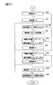
図7は再装着された収納庫を認識するための主制御部の処理を示す図である。ステップ301において、紙幣取り扱い装置の起動後、主制御部111は収納庫回線制御部を制御して、収納庫記憶部116に記憶した収納庫識別情報(例えば、入金庫、出金庫、リサイクル庫というような収納庫のタイプ情報、あるいは前記収納庫が格納する万円札、千円札、USドル札というような金種情報)を取得する。ステップ302において、取得した収納庫識別情報を主記憶部112に記憶する。ステップ303において、扉11の開閉を監視し、扉の開を検出するとステップに進む。ステップ304において、主記憶部112を参照して、収納庫の定位置外れを記憶しているか否かを検索する。定位置外れを記憶している場合はステップ305に進み、そうでない場合はステップ309に進む。ステップ305において、収納庫が装着位置から外れているすなわち定位置外れであるか否かを判定する。定位置外れであればステップ306に進み、そうでなければステップ309に進む。ステップ306において、定位置はずれを主記憶部112に記憶する。ステップ307において、収納庫が装着位置すなわち定位置にあるか否かを判定する。定位置にある場合はステップ308に進み、そうでない場合はステップ309に進む。ステップ308において、収納庫が装着位置に戻されたこと、すなわち収納庫の再装着を主記憶に記憶する。ステップ309において、扉の閉を検出したか否かを判定する。扉の閉を検出した場合はステップ310に進み、そうでない場合はステップ304に進む。
【0020】
ステップ310において、主記憶112を検索して収納庫再装着の記録の有無を判定し、記録があればステップ311に進み、そうでなければ処理を終了する。ステップ311において、収納庫回線制御部115を制御して収納庫識別情報記憶部116に記憶した収納庫識別情報を取得する。ステップ312において、取得した収納庫識別情報が着脱の前後で異なっているかを判定する。収納庫識別情報が異なる場合はステップ313に進み、そうでない場合は処理を終了する。ステップ313において、更新された収納庫識別情報を主記憶部112に記憶する。ステップ314において、更新された収納庫識別情報を上位装置101に報告する。上位装置101は、装着されている収納庫の構成を表示して、収納庫を誤って装着していないか係員に確認させる。
【0021】
図8ないし図9は、収納庫識別情報記憶部に収納庫識別情報を記憶するための主制御部の処理を示す図である。ステップ401において、パネルキー20の「A」キーがオンされるのを待つ。「A」キーがオンされるとステップ402に進む。ステップ402において、「G」キーが押下されたか否かを検出する。「G」キーが押下された場合はステップ403に進み、そうでない場合はステップ404に進む。ステップ403において、例えばカウンタ21の上位桁のカウント値Xを「1」増加する。ステップ404において、「H」キーが押下されたか否かを検出する。「H」キーが押下された場合はステップ405に進み、そうでない場合はステップ406に進む。ステップ405において、例えばカウンタ21の下位桁のカウント値Yを「1」増加する。ステップ406において、「C」キーが押下されたか否かを検出する。「C」キーが押下された場合はステップ410に進み、そうでない場合はステップ407に進む。ステップ407において、「A」キーがオフされたか否かを検出する。「A」キーがオフされた場合は処理を終了し、そうでない場合はステップ402に進む。
【0022】
ステップ410において、収納庫識別情報設定モードであるか否かを判定する。収納庫識別情報設定モードであればステップ413に進み、そうでない場合はステップ411に進む。ステップ411において、例えばX=3かつY=1に設定されているか否かを判定する。X=3かつY=1に設定されている場合はステップ412に進み、そうでない場合はステップステップ407に進む。ステップ412において、収納庫識別情報設定モードに移行する。ステップ413において、収納庫識別情報を記憶させる対象となる収納庫の例えば収納庫番号は設定済か否かを判定する。設定済であればステップ415に進み、そうでなければステップ414に進む。ステップ414において、対象収納庫番号を設定する(パネルキー20のGキー、およびHキーを操作して入力した収納庫番号を主制御部に設定する)。ステップ415において、収納庫のタイプ情報は設定済か否かを判定する。設定済であればステップ418に進み、そうでなければステップ416に進む。ステップ416において、収納庫回線制御部115に、例えば収納庫のタイプを入金庫とするタイプ情報を(例えばコード02)を記憶させるよう指示する。ステップ417において、タイプ情報を設定する(パネルキー20のGキー、およびHキーを操作して入力したタイプ情報を設定する)。ステップ418において、収納庫の金種情報は設定済か否かを判定する。設定済であればステップ407に進み、そうでなければステップ419に進む。ステップ419において、収納庫回線制御部115に、例えば収納庫の金種を千円札とする金種情報(例えばコード01)を記憶させるよう指示する。ステップ420において、金種情報を設定する(パネルキー20のGキー、およびHキーを操作して入力した金種情報を設定する)。
【0023】
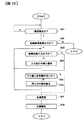
図10は、紙幣収納庫を着脱して運用する紙幣取扱装置において、装置内の在高を管理するための主制御部111の処理を示す図である。ステップ501において、主制御部111は、扉の開閉を監視し、扉の閉を検出したらステップ502に進む。ステップ502において、紙幣収納庫の再装着が主記憶部112に記録されているか検索し、記録していたらステップ503に進み、記録していなかったら終了する。ステップ503において、運用を再開時に係員により再装着した紙幣収納庫の紙幣枚数が入力されたかチェックし、入力せずに運用を再開しようとした場合はステップ504に進み、入力された場合はステップ505に進む。ステップ504において、紙幣枚数が入力されていないことを上位装置101に伝送する。上位装置101は係員が紙幣枚数の入力を忘れていることを表示して、係員に紙幣枚数を入力するようにガイダンスする。ステップ505において、係員により入力された紙幣枚数と前記のように計数または算出した紙幣枚数を比較し、差が大きい場合はステップ506に進み、差が小さい場合はステップ507に進む。ステップ506において、再装着した紙幣収納庫の計数または算出した紙幣枚数より入力された紙幣枚数が多すぎるあるいは少なすぎることを上位装置に伝送する。上位装置101は紙幣枚数を入力し直すよう表示して係員にガイダンスする。ステップ507において、紙幣取扱装置が管理する装置内の紙幣の在高を係員により入力された紙幣枚数に置き換える。ステップ508において、更新した在高を上位装置に伝送する。
【0024】
以上説明したように本実施形態によれば、装置の運用を中断して、係員が紙幣の補充、抜き取り、収納庫の抜き取り、再装着等の操作を行った場合は、装置の運用を再開する前に収納庫の紙幣残枚数あるいは残量状況をを算出し、上位装置に報告して残量状況を表示させることができる。このため係員は着脱した収納庫紙幣残量を確認することができ、また、紙幣取扱装置の誤動作を防止することができ、装置をダウンさせることなく、取引を継続することができる。
【0025】
また、係員がタイプの異なる収納庫、あるいは金種の異なる収納庫を装着した場合、運用を再開する前に収納庫の構成を再認識し,上位装置に報告して収納庫の構成を表示させることができる。このため係員は着脱した収納庫の種別を確認することができ、また、紙幣取扱装置の誤動作を防止することができ、装置をダウンさせることなく、取引を継続することができる。
【0026】
また、タイプの異なる各種の収納庫あるいは各種の金種に対応可能であるため、各国通貨に対しても速やかに対応することが可能である。
【0027】
また、紙幣取扱装置を単体で動作させるときに使用するパネルキーを用いることで,収納庫を識別するための情報(例えば、入金庫,出金庫,リサイクル庫等の収納庫のタイプ情報、あるいは収納した金種(万円札、千円札、USドル札等)を表す金種情報)を収納庫記憶部に簡単に記憶することができる。
【0028】
また、係員が紙幣枚数を紙幣取扱装置に入力する手段を用いることで、収納庫を着脱しても在高を管理することができる。
【0029】
【発明の効果】
以上説明したように本発明によれば、装着した収納庫にかかる情報を取得し係員に連絡できる紙幣取り扱い装置を提供することができる。
【図面の簡単な説明】
【図1】本発明の実施形態にかかる紙幣取扱装置を示す図である。
【図2】紙幣取り扱い装置の制御ブロックを示す図である。
【図3】紙幣残枚数を算出する際の主制御部の処理を示す図である。
【図4】紙幣残枚数を算出する際の主制御部の処理を示す図である。
【図5】紙幣残枚数を算出する際の主制御部の処理を示す図である。
【図6】紙幣残枚数を算出する際の押板の操作を示す図である。
【図7】装着した収納庫を認識するための主制御部の処理を示す図である。
【図8】収納庫識別情報記憶部に識別情報を記憶するための主制御部の処理を示す図である。
【図9】収納庫識別情報記憶部に識別情報を記憶するための主制御部の処理を示す図である。
【図10】紙幣取扱装置の在高を管理するための主制御部の処理を示す図である。
【符号の説明】
1 入出金部
2 搬送路
3 紙幣判別部
4 紙幣一時保管庫
5 紙幣収納庫
6 押板
7 通過センサ
8 ゲート
9 リジェクト券収納庫
10 筐体
10a 装着部
11 扉
12 開閉検出センサ
13 収納庫定位置検出センサ
14 押圧検出センサ
15 空検出センサ
16,17 押板センサ
18 シャッタ
19 入出金部押板
20 パネルキー
21 カウンタ
101 上位装置
102 上位回線接続部
103 駆動モータ制御部
104 搬送路位置計数部
105 センサ制御部
106 ゲート制御部
107 入出金制御部
108 一時保管庫制御部
109 押板駆動モータ制御部
110 押板移動量計数部
111 主制御部
112 主記憶部
113 紙幣判別部回線制御部
114 紙幣判別部制御部
115 収納庫回線制御部
116 収納庫記憶部[0001]
BACKGROUND OF THE INVENTION
The present invention relates to a banknote handling apparatus, and more particularly to a banknote handling apparatus that can be used with a banknote storage attached and detached.
[0002]
[Prior art]
Japanese Patent Application Laid-Open No. 11-175801 discloses a bill handling apparatus including a deposit / withdrawal port, a conveyance path, a bill discriminating unit, a temporary storage, and a bill storage. Moreover, the banknote storage in the banknote handling device is configured with an entrance safe, a safe deposit box, a recycling store, a loading / collecting store, etc., and the banknote storage configured by these is detachably attached to the banknote handling device. It is shown.
[0003]
[Problems to be solved by the invention]
In the conventional banknote handling apparatus, when the banknote storage is attached to or detached from the banknote handling apparatus, the banknote handling apparatus cannot acquire the information on the number of banknotes present in the storage mounted on itself. For this reason, even if the clerk is filled with banknotes and the storage is full, an abnormality may occur when the deposit transaction is executed after resuming the transaction and further banknotes are stored in the full storage . In addition, even though the clerk collects banknotes and the storage is empty, an abnormality may occur when the withdrawal transaction is executed after the transaction is resumed to extract the banknotes from the empty storage.
[0004]
In addition, when the banknote storage is attached to or detached from the banknote handling device, the banknote handling device can store the denomination (10,000 yen bill, thousand yen bill, etc.) stored in the storage installed on the banknote storage device, Information on safes, safes, recycle bins, etc.) cannot be obtained. For this reason, even if a different denomination storage is installed, try to extract different banknotes from the storage, try to store different banknotes, or store banknotes in a dedicated storage for withdrawals. Or an error may occur when trying to extract banknotes from a deposit-only storage.
[0005]
This invention is made | formed in view of the said problem, and provides the banknote handling apparatus which can acquire the information concerning the mounted storage and can contact an attendant.
[0006]
[Means for Solving the Problems]
The present invention employs the following means in order to solve the above problems.
[0007]
In a banknote handling apparatus for handling banknotes, a depositing / withdrawing unit for depositing / withdrawing banknotes, and a banknote that can be attached to and detached from the banknote handling apparatus and deposited from the depositing / withdrawing section A storage unit that stores information indicating that the storage is removed from the bill handling device in response to a detection result of the sensor. And a depositing / withdrawing unit and the plurality of storages, and a transport path for transporting banknotes, and a control unit, wherein the plurality of storages store the banknotes stored in the storages. The control unit has a pressing plate to be pressed, and the control unit stores the information that the storage is removed from the bill handling device in the storage unit. When it is detected that the mounted on the handling device, The push plate of該装wearing has been in storage case according to the storage box is mounted to drive detects a bill amount of banknotes stored in the repository.
[0008]
DETAILED DESCRIPTION OF THE INVENTION
Embodiments of the present invention will be described below with reference to FIGS. FIG. 1 is a diagram showing a banknote handling apparatus according to an embodiment of the present invention, and FIG. 2 is a diagram showing a control block of the banknote handling apparatus. In these drawings, 1 is a deposit / withdrawal unit, 2 is a banknote transport path for transporting banknotes to various places in the banknote handling apparatus, 3 is a banknote suitable for withdrawal by discriminating the authenticity of a banknote, denomination, etc. A bill discriminating unit for discriminating between a (correct ticket) and a bill (rejected bill) that is not suitable for withdrawal, 4 is a retractable bill temporary storage, 5 is a bill storage, and 6 is installed in the bill storage 5 A push plate that is driven by an electric motor or the like to press a bill and release the press. The pressing plate 6 includes a pressing plate position counter that detects the position of the pressing plate 6, and can detect the pressing plate position (the number of banknotes when pressed) from the count value of the counter.
[0009]
101 is a host device of the banknote handling device, 102 is a host line connection unit connected to the
[0010]
When making a deposit transaction using this bill handling apparatus, a user first inserts a bill into the deposit /
[0011]
After the deposit transaction is repeated several times, when the
[0012]
When making a withdrawal transaction, the banknote handling device separates the banknote from the designated
[0013]
After the withdrawal transaction is repeated several times, if the
[0014]
FIGS. 3 to 5 are diagrams illustrating processing of the
[0015]
In
[0016]
In
[0017]
In
[0018]
In
[0019]
FIG. 7 is a diagram showing processing of the main control unit for recognizing the remounted storage. In
[0020]
In
[0021]
FIG. 8 thru | or FIG. 9 is a figure which shows the process of the main control part for memorize | storing storage identification information in a storage identification information storage part. In
[0022]
In
[0023]
FIG. 10 is a diagram showing processing of the
[0024]
As described above, according to the present embodiment, when the operation of the apparatus is interrupted and the clerk performs operations such as banknote replenishment, extraction, storage box extraction, and remounting, the operation of the apparatus is resumed. It is possible to calculate the remaining number of bills or the remaining amount in the storage before and report it to the host device to display the remaining amount. For this reason, the clerk can confirm the remaining amount of the stored banknote banknotes, can prevent the banknote handling apparatus from malfunctioning, and can continue the transaction without bringing down the apparatus.
[0025]
In addition, when a staff member installs a different type of storage or a storage of a different denomination, before resuming operation, reconfirm the storage configuration and report it to the host device to display the storage configuration. be able to. For this reason, the clerk can confirm the type of the detached storage, can prevent the banknote handling apparatus from malfunctioning, and can continue the transaction without bringing down the apparatus.
[0026]
Moreover, since it can respond | correspond to various storages or various denominations of a different type, it can respond rapidly also to the currency of each country.
[0027]
Also, by using a panel key used when operating the bill handling device alone, information for identifying the storage (for example, type information of storage such as an inbox, a safe, a recycle bin, or storage Denominations (denomination information representing 10,000 yen bills, thousand yen bills, US dollar bills, etc.) can be easily stored in the storage unit.
[0028]
Moreover, by using the means for the clerk to input the number of banknotes into the banknote handling device, the amount in stock can be managed even if the storage is attached or detached.
[0029]
【The invention's effect】
As described above, according to the present invention, it is possible to provide a banknote handling apparatus that can acquire information related to a mounted storage and can contact an attendant.
[Brief description of the drawings]
FIG. 1 is a diagram showing a banknote handling apparatus according to an embodiment of the present invention.
FIG. 2 is a diagram showing a control block of the bill handling apparatus.
FIG. 3 is a diagram illustrating processing of a main control unit when calculating the remaining number of banknotes.
FIG. 4 is a diagram illustrating processing of a main control unit when calculating the remaining number of banknotes.
FIG. 5 is a diagram illustrating processing of a main control unit when calculating the remaining number of banknotes.
FIG. 6 is a diagram illustrating a push plate operation when calculating the remaining number of banknotes.
FIG. 7 is a diagram illustrating processing of a main control unit for recognizing a mounted storage.
FIG. 8 is a diagram showing processing of a main control unit for storing identification information in a storage unit identification information storage unit.
FIG. 9 is a diagram illustrating processing of a main control unit for storing identification information in a storage unit identification information storage unit.
FIG. 10 is a diagram showing processing of a main control unit for managing the banknote handling apparatus.
[Explanation of symbols]
DESCRIPTION OF
Claims (13)
紙幣を入出金する入出金部と、
前記紙幣取扱装置に着脱可能であって、前記入出金部から入金される紙幣又は前記入出金部から出金する紙幣を収納する複数の収納庫と、
前記収納庫の着脱を検出するセンサと、
前記センサの検出結果に対応して、前記収納庫が前記紙幣取扱装置から取り外されているという情報を記憶する記憶部と、
前記入出金部と前記複数の収納庫とを接続し、紙幣を搬送する搬送路と、
制御部とを具備し、
前記複数の収納庫は、該収納庫内に収納された紙幣を押圧する押板を有し、
前記制御部は、前記記憶部に前記収納庫が前記紙幣取扱装置から取り外されているという情報を記憶している場合に、前記センサが、該収納庫が前記紙幣取扱装置に装着されていることを検出すると、該収納庫が装着されていることに応じて該装着された収納庫内の前記押板を駆動して該収納庫に収納されている紙幣の紙幣量を検出することを特徴とする紙幣取扱装置。In banknote handling equipment that handles banknotes,
A deposit / withdrawal unit for depositing / withdrawing banknotes;
A plurality of storages for storing banknotes that can be attached to and detached from the banknote handling device and that are deposited from the deposit / withdrawal unit or banknotes to be dispensed from the deposit / withdrawal unit;
A sensor for detecting attachment and detachment of the storage;
Corresponding to the detection result of the sensor, a storage unit that stores information that the storage is removed from the bill handling device;
A transport path that connects the deposit / withdrawal unit and the plurality of storages to transport bills;
A control unit,
The plurality of storages have a pressing plate that presses banknotes stored in the storage.
When the control unit stores information that the storage is removed from the banknote handling device in the storage unit, the sensor is mounted on the banknote handling device . Upon detection of a feature to detect a bill amount of the bill by driving the push plate of該装wearing has been in storage case according to the storage case is mounted is accommodated in the storage box Banknote handling equipment.
前記収納庫に収納された紙幣の紙幣量が少ないことを検出する残量少検出部を有し、
前記残量少検出部が前記収納庫の前記押板を検出したとき、前記制御部は、その残量少に基づく紙幣量を報告することを特徴とする紙幣取扱装置。In the bill handling device according to claim 1,
Having a low remaining amount detection unit for detecting that the amount of banknotes stored in the storage is small;
When the low remaining amount detection unit detects the push plate of the storage, the control unit reports the amount of banknotes based on the low remaining amount.
前記収納庫に収納された紙幣の紙幣量が満杯であることを検出する満杯検出部を有し、
前記満杯検出部が前記収納庫の前記押板を検出したとき、前記制御部は、その満杯に基
づく紙幣量を報告することを特徴とする紙幣取扱装置。In the bill handling device according to claim 1,
A full detection unit for detecting that the amount of banknotes stored in the storage is full;
When the full detection unit detects the push plate of the storage, the control unit reports the amount of banknotes based on the fullness.
前記収納庫に収納された紙幣の紙幣量が少ないことを検出する残量少検出部と、
前記収納庫に収納された紙幣の紙幣量が満杯であることを検出する満杯検出部とを有し、
前記残量少検出部及び前記満杯検出部が前記収納庫の前記押板を検出しなかったとき、前記制御部は、残量少に基づく紙幣量と満杯に基づく紙幣量との和を半分に割って算出し、その算出した紙幣量を報告することを特徴とする紙幣取扱装置。In the bill handling device according to claim 1,
A low remaining amount detection unit for detecting that the amount of banknotes stored in the storage is small;
A full detection unit for detecting that the amount of banknotes stored in the storage is full,
When the low remaining amount detection unit and the full detection unit do not detect the push plate of the storage, the control unit halves the sum of the amount of banknotes based on low remaining amount and the amount of banknotes based on fullness. Dividing and calculating and reporting the calculated banknote amount, The banknote handling apparatus characterized by the above-mentioned.
前記複数の収納庫が前記装置にセットされているか否かを検出する収納庫検出部を有す
ることを特徴とする紙幣取扱装置。In the bill handling device according to claim 1,
A bill handling apparatus comprising: a storage detector that detects whether or not the plurality of storages are set in the device.
前記収納庫検出部によって前記収納庫が再度セットされたことを検出したとき、前記制御部は、前記収納庫が再度セットされたことを記憶すると共に前記複数の収納庫固有に割り当てられた収納庫情報を取得することを特徴とする紙幣取扱装置。In the bill handling device according to claim 5,
When the storage detection unit detects that the storage has been set again, the control unit stores that the storage has been set again and stores storages uniquely assigned to the plurality of storages. A bill handling apparatus characterized by acquiring information.
前記制御部は、前記収納庫から取得する前記収納庫情報に、紙幣の枚数が入力されているか否かを判断することを特徴とする紙幣取扱装置。In the bill handling device according to claim 6,
The said control part judges whether the number of banknotes is input into the said storage information acquired from the said storage, The banknote handling apparatus characterized by the above-mentioned.
前記収納庫情報に入力された紙幣の枚数が含まれていない場合、前記制御部は、入力忘れの旨を表示することを特徴とする紙幣取扱装置。In the bill handling device according to claim 7,
When the number of banknotes input in the storage information is not included, the control unit displays that the input is forgotten.
前記制御部は、前記収納庫から取得する入力された紙幣枚数と、前記押板を駆動して得られた紙幣量とを比較することを特徴とする紙幣取扱装置。In the bill handling device according to claim 7,
The said control part compares the input banknote number acquired from the said storage with the banknote amount obtained by driving the said push plate, The banknote handling apparatus characterized by the above-mentioned.
前記比較が所定の範囲内であれば、前記制御部は、前記収納庫に収納された紙幣量として、前記収納庫から取得する紙幣枚数で在高を更新することを特徴とする紙幣取扱装置。In the bill handling device according to claim 9,
If the comparison is within a predetermined range, the control unit updates the stock amount with the number of banknotes acquired from the storage as the amount of banknotes stored in the storage.
前記比較が所定の範囲外の場合、前記制御部は、前記収納庫から取得する紙幣枚数の再入力指示を表示することを特徴とする紙幣取扱装置。In the bill handling device according to claim 9,
When the comparison is outside a predetermined range, the control unit displays a re-input instruction for the number of banknotes acquired from the storage.
前記複数の収納庫の一部又は全部が前記装置に再セットされたことに起因して、
前記制御部は、再セットされた収納庫からその収納庫を識別する識別情報を取得し、予め登録された各収納庫の情報と適合するか否かを判断することを特徴とする紙幣取扱装置。In the bill handling device according to claim 1,
Due to part or all of the plurality of storages being reset in the device,
The control unit acquires identification information for identifying the storage from the reset storage, and determines whether or not it matches with information of each storage registered in advance. .
前記制御部が前記収納庫から取得する識別情報には、収納庫のタイプを示すタイプ情報又は収納庫が収納する紙幣の金種情報を含むことを特徴とする紙幣取扱装置。In the bill handling device according to claim 12,
The identification information acquired from the storage by the control unit includes type information indicating a type of storage or denomination information of a banknote stored in the storage.
Priority Applications (4)
| Application Number | Priority Date | Filing Date | Title |
|---|---|---|---|
| JP2000388961A JP4044281B2 (en) | 2000-12-21 | 2000-12-21 | Banknote handling equipment |
| TW090129709A TW502228B (en) | 2000-12-21 | 2001-11-30 | Bill handling machine |
| KR10-2001-0081188A KR100450131B1 (en) | 2000-12-21 | 2001-12-19 | Bill handling machine |
| US10/022,336 US6805343B2 (en) | 2000-12-21 | 2001-12-20 | Bill handling machine for determining amount of bills in storage boxes |
Applications Claiming Priority (1)
| Application Number | Priority Date | Filing Date | Title |
|---|---|---|---|
| JP2000388961A JP4044281B2 (en) | 2000-12-21 | 2000-12-21 | Banknote handling equipment |
Publications (3)
| Publication Number | Publication Date |
|---|---|
| JP2002190051A JP2002190051A (en) | 2002-07-05 |
| JP2002190051A5 JP2002190051A5 (en) | 2004-12-02 |
| JP4044281B2 true JP4044281B2 (en) | 2008-02-06 |
Family
ID=18855608
Family Applications (1)
| Application Number | Title | Priority Date | Filing Date |
|---|---|---|---|
| JP2000388961A Expired - Fee Related JP4044281B2 (en) | 2000-12-21 | 2000-12-21 | Banknote handling equipment |
Country Status (4)
| Country | Link |
|---|---|
| US (1) | US6805343B2 (en) |
| JP (1) | JP4044281B2 (en) |
| KR (1) | KR100450131B1 (en) |
| TW (1) | TW502228B (en) |
Families Citing this family (36)
| Publication number | Priority date | Publication date | Assignee | Title |
|---|---|---|---|---|
| US7025347B2 (en) * | 2002-09-17 | 2006-04-11 | Canon Denshi Kabushiki Kaisha | Sheet aligning apparatus |
| US7169094B2 (en) * | 2002-10-09 | 2007-01-30 | Corepole, Inc. | Circular fitness apparatus |
| CA2680866C (en) * | 2002-10-18 | 2011-04-12 | Diebold, Incorporated | Automated banking machine which dispenses, receives and stores notes and other financial instrument sheets |
| JP4332379B2 (en) * | 2003-07-29 | 2009-09-16 | 日立オムロンターミナルソリューションズ株式会社 | Banknote handling equipment |
| JP4174442B2 (en) | 2004-03-15 | 2008-10-29 | 富士通株式会社 | Paper sheet bundle height detection method and paper sheet handling apparatus |
| KR100552232B1 (en) | 2004-04-27 | 2006-02-17 | 노틸러스효성 주식회사 | Device for initializing recycle box in auto teller machine and method thereof |
| GB0420441D0 (en) * | 2004-09-14 | 2004-10-20 | Ncr Int Inc | Sensing arrangement |
| JP4631391B2 (en) * | 2004-10-27 | 2011-02-16 | 沖電気工業株式会社 | Banknote deposit and withdrawal device |
| GB0426137D0 (en) * | 2004-11-26 | 2004-12-29 | Money Controls Ltd | A device for processing sheet objects such as banknotes |
| US7523929B2 (en) * | 2005-11-04 | 2009-04-28 | Pitney Bowes Inc. | Shingle mode media item feed arrangement |
| US7341179B2 (en) * | 2005-12-16 | 2008-03-11 | Ncr Corporation | Media cassette sensing system |
| KR100750793B1 (en) * | 2006-05-16 | 2007-08-20 | 노틸러스효성 주식회사 | Structure of sheet feed route in atm |
| DE102006040780A1 (en) * | 2006-08-31 | 2008-03-06 | Giesecke & Devrient Gmbh | Device for processing banknotes |
| FR2906235B1 (en) * | 2006-09-21 | 2009-05-29 | Solystic Sas | DEVICE FOR DEPILING POSTAL SHIPMENTS WITH OPTIMIZED MANAGEMENT OF DEPILING CONDITIONS |
| JP4965954B2 (en) * | 2006-09-29 | 2012-07-04 | 株式会社東芝 | Paper sheet processing equipment |
| US7980461B1 (en) * | 2006-10-03 | 2011-07-19 | Diebold Self-Service Systems Division Of Diebold, Incorporated | Card activated automated banking machine system and method |
| KR100868945B1 (en) * | 2007-06-26 | 2008-11-17 | 주식회사 청호컴넷 | Apparatus and method for recognizing the existence of paper medium in recycle box |
| JP5081508B2 (en) * | 2007-06-29 | 2012-11-28 | 日立オムロンターミナルソリューションズ株式会社 | Paper sheet handling device and paper sheet processing system |
| JP5220385B2 (en) * | 2007-11-02 | 2013-06-26 | 日立オムロンターミナルソリューションズ株式会社 | Banknote deposit and withdrawal mechanism and automatic cash transaction equipment |
| JP5188167B2 (en) * | 2007-12-20 | 2013-04-24 | 株式会社ユニバーサルエンターテインメント | Paper sheet processing equipment |
| US8251281B1 (en) * | 2008-06-27 | 2012-08-28 | Diebold Self-Service Systems Division Of Diebold, Incorporated | Automated banking system controlled responsive to data bearing records |
| JP5205292B2 (en) * | 2009-01-16 | 2013-06-05 | ローレル機械株式会社 | Banknote handling machine |
| JP5268667B2 (en) | 2009-01-16 | 2013-08-21 | ローレル機械株式会社 | Banknote handling machine |
| KR101584813B1 (en) | 2009-07-31 | 2016-01-12 | 주식회사 엘지씨엔에스 | Media stacking apparatus |
| IT1399673B1 (en) * | 2010-04-22 | 2013-04-26 | Barani | ANTI-BREAKING SYSTEM FOR EQUIPMENT BANCOMAT TYPE. |
| JP5602674B2 (en) * | 2011-05-16 | 2014-10-08 | 日立オムロンターミナルソリューションズ株式会社 | Paper sheet processing apparatus and identification algorithm update program |
| JP5759289B2 (en) * | 2011-06-30 | 2015-08-05 | グローリー株式会社 | Banknote processing apparatus and banknote management method |
| TWI456529B (en) * | 2011-07-26 | 2014-10-11 | 日立歐姆龍金融系統有限公司 | Paper sheet processing device |
| JP5788733B2 (en) | 2011-08-09 | 2015-10-07 | グローリー株式会社 | Money handling apparatus, money management system, and money management method |
| US9934642B2 (en) * | 2014-12-18 | 2018-04-03 | Crane Payment Innovations, Inc. | Multiclass logical document recycler management |
| KR102255885B1 (en) * | 2014-12-31 | 2021-05-26 | 효성티앤에스 주식회사 | Control apparatus for receiving bills and control method thereof |
| KR101676168B1 (en) * | 2015-05-12 | 2016-11-14 | 주식회사 엘지씨엔에스 | Financial device and controlling method thereof |
| JP6790642B2 (en) * | 2016-09-16 | 2020-11-25 | 富士電機株式会社 | Banknote processing device |
| JP6857091B2 (en) * | 2017-06-26 | 2021-04-14 | グローリー株式会社 | Money processing system, money processing machine, money change machine and money processing method |
| US11398124B2 (en) | 2017-06-22 | 2022-07-26 | Glory Ltd. | Money handling system, money handling machine, and money handling method |
| CN113345156B (en) * | 2021-04-23 | 2022-08-09 | 东方通信股份有限公司 | Device and method for detecting number of paper money in paper money box |
Family Cites Families (20)
| Publication number | Priority date | Publication date | Assignee | Title |
|---|---|---|---|---|
| GB2135494B (en) * | 1983-01-26 | 1986-05-21 | Tokyo Shibaura Electric Co | Automatic bank note transaction apparatus |
| JPS59149564A (en) * | 1983-02-15 | 1984-08-27 | Toshiba Corp | Automatic transaction system |
| US4681229A (en) * | 1983-12-12 | 1987-07-21 | Glory Kogyo Kabushiki Kaisha | Note sorting and counting apparatus |
| KR890004965B1 (en) * | 1984-08-06 | 1989-12-02 | 가부시기가이샤 도시바 | Automatic bank note transaction system |
| US5099423A (en) * | 1985-06-27 | 1992-03-24 | Diebold, Incorporated | Method and apparatus for account settlement in an ATM |
| JPH0823900B2 (en) * | 1985-08-30 | 1996-03-06 | 株式会社日立製作所 | Automatic bill replenishment control method for automatic teller machine |
| JPH06183598A (en) * | 1992-12-24 | 1994-07-05 | Fujitsu Ltd | Paper sheet housing box |
| JPH06293467A (en) * | 1993-04-07 | 1994-10-21 | Oki Electric Ind Co Ltd | Near full detecting structure for bill receiving and paying machine |
| KR0109579Y1 (en) * | 1993-06-30 | 1997-12-13 | Lg Electronics Inc | Bill remnants perception apparatus for bill payment machine |
| US5513773A (en) * | 1995-02-27 | 1996-05-07 | Technitrol, Inc. | Single denomination bill dispensing apparatus |
| KR19980038706A (en) * | 1996-11-26 | 1998-08-05 | 구자홍 | Accumulation level detection device for bills or checks |
| KR19990026397A (en) * | 1997-09-24 | 1999-04-15 | 구자홍 | Residual Bank Release Device and Automatic Method of Cash Dispenser |
| JPH11175801A (en) | 1997-10-06 | 1999-07-02 | Hitachi Ltd | Paper sheets handling device |
| JP3514999B2 (en) * | 1998-01-29 | 2004-04-05 | ローレルバンクマシン株式会社 | Bill feeding device |
| KR20000025371A (en) * | 1998-10-10 | 2000-05-06 | 구자홍 | Apparatus and method for detecting note remaining amount in cash automatic dispenser |
| JP3631928B2 (en) * | 1999-09-30 | 2005-03-23 | 富士通株式会社 | Paper sheet feeding unit and paper sheet handling apparatus |
| GB2356728B (en) * | 1999-10-09 | 2001-12-12 | Ncr Int Inc | Replenishment arrangements for automated teller machines |
| JP3977982B2 (en) * | 2000-05-19 | 2007-09-19 | 日立オムロンターミナルソリューションズ株式会社 | Banknote storage and release box and banknote deposit and withdrawal machine |
| JP3959706B2 (en) * | 2001-03-01 | 2007-08-15 | 日立オムロンターミナルソリューションズ株式会社 | Banknote handling equipment |
| GB0124867D0 (en) * | 2001-10-17 | 2001-12-05 | Ncr Int Inc | Media cassette |
-
2000
- 2000-12-21 JP JP2000388961A patent/JP4044281B2/en not_active Expired - Fee Related
-
2001
- 2001-11-30 TW TW090129709A patent/TW502228B/en not_active IP Right Cessation
- 2001-12-19 KR KR10-2001-0081188A patent/KR100450131B1/en not_active IP Right Cessation
- 2001-12-20 US US10/022,336 patent/US6805343B2/en not_active Expired - Lifetime
Also Published As
| Publication number | Publication date |
|---|---|
| US6805343B2 (en) | 2004-10-19 |
| TW502228B (en) | 2002-09-11 |
| KR100450131B1 (en) | 2004-09-30 |
| JP2002190051A (en) | 2002-07-05 |
| US20020079361A1 (en) | 2002-06-27 |
| KR20020050709A (en) | 2002-06-27 |
Similar Documents
| Publication | Publication Date | Title |
|---|---|---|
| JP4044281B2 (en) | Banknote handling equipment | |
| JP4332379B2 (en) | Banknote handling equipment | |
| JPH0922476A (en) | Automatic transaction device and method for handling rejected money in automatic transaction device | |
| JP5607457B2 (en) | Paper sheet handling equipment | |
| JP5087889B2 (en) | Cash processing equipment | |
| JPH02306390A (en) | Automatic transaction machine | |
| US20220207951A1 (en) | Paper sheet processing device | |
| JP2532668B2 (en) | Deposit / withdrawal device | |
| JP2918318B2 (en) | Automatic teller machine | |
| CN210836312U (en) | Cash processing equipment | |
| JP2726338B2 (en) | Control method of deposit / withdrawal device | |
| JP3044664B2 (en) | Banknote deposit / withdrawal device | |
| JP2006184991A (en) | Cash automatic transaction device | |
| JPH0357096A (en) | Cash receiving / dispensing device | |
| JP3157075B2 (en) | Cash deposit and withdrawal device | |
| JP2503081B2 (en) | Cash deposit / withdrawal device | |
| JPH0319010Y2 (en) | ||
| JPH07129819A (en) | Paper money reception and payment device | |
| JP2902764B2 (en) | Cash deposit and withdrawal device | |
| JP3756996B2 (en) | Sales management system | |
| JPH09297872A (en) | Paper money collection processor | |
| JPS62219099A (en) | Paper money teller machine | |
| JPH0313453A (en) | Bill delivery device | |
| JPH1173537A (en) | Automatic teller machine | |
| JPH02285485A (en) | Cash teller machine |
Legal Events
| Date | Code | Title | Description |
|---|---|---|---|
| A521 | Request for written amendment filed |
Free format text: JAPANESE INTERMEDIATE CODE: A523 Effective date: 20031215 |
|
| A621 | Written request for application examination |
Free format text: JAPANESE INTERMEDIATE CODE: A621 Effective date: 20031215 |
|
| A711 | Notification of change in applicant |
Free format text: JAPANESE INTERMEDIATE CODE: A712 Effective date: 20050113 |
|
| A977 | Report on retrieval |
Free format text: JAPANESE INTERMEDIATE CODE: A971007 Effective date: 20060825 |
|
| A131 | Notification of reasons for refusal |
Free format text: JAPANESE INTERMEDIATE CODE: A131 Effective date: 20060912 |
|
| A521 | Request for written amendment filed |
Free format text: JAPANESE INTERMEDIATE CODE: A523 Effective date: 20061113 |
|
| A02 | Decision of refusal |
Free format text: JAPANESE INTERMEDIATE CODE: A02 Effective date: 20070327 |
|
| A521 | Request for written amendment filed |
Free format text: JAPANESE INTERMEDIATE CODE: A523 Effective date: 20070525 |
|
| A911 | Transfer to examiner for re-examination before appeal (zenchi) |
Free format text: JAPANESE INTERMEDIATE CODE: A911 Effective date: 20070601 |
|
| A131 | Notification of reasons for refusal |
Free format text: JAPANESE INTERMEDIATE CODE: A131 Effective date: 20070626 |
|
| A131 | Notification of reasons for refusal |
Free format text: JAPANESE INTERMEDIATE CODE: A131 Effective date: 20070918 |
|
| A521 | Request for written amendment filed |
Free format text: JAPANESE INTERMEDIATE CODE: A523 Effective date: 20071002 |
|
| TRDD | Decision of grant or rejection written | ||
| A01 | Written decision to grant a patent or to grant a registration (utility model) |
Free format text: JAPANESE INTERMEDIATE CODE: A01 Effective date: 20071106 |
|
| A61 | First payment of annual fees (during grant procedure) |
Free format text: JAPANESE INTERMEDIATE CODE: A61 Effective date: 20071115 |
|
| R150 | Certificate of patent or registration of utility model |
Free format text: JAPANESE INTERMEDIATE CODE: R150 |
|
| FPAY | Renewal fee payment (event date is renewal date of database) |
Free format text: PAYMENT UNTIL: 20101122 Year of fee payment: 3 |
|
| FPAY | Renewal fee payment (event date is renewal date of database) |
Free format text: PAYMENT UNTIL: 20101122 Year of fee payment: 3 |
|
| FPAY | Renewal fee payment (event date is renewal date of database) |
Free format text: PAYMENT UNTIL: 20111122 Year of fee payment: 4 |
|
| FPAY | Renewal fee payment (event date is renewal date of database) |
Free format text: PAYMENT UNTIL: 20111122 Year of fee payment: 4 |
|
| FPAY | Renewal fee payment (event date is renewal date of database) |
Free format text: PAYMENT UNTIL: 20121122 Year of fee payment: 5 |
|
| FPAY | Renewal fee payment (event date is renewal date of database) |
Free format text: PAYMENT UNTIL: 20121122 Year of fee payment: 5 |
|
| FPAY | Renewal fee payment (event date is renewal date of database) |
Free format text: PAYMENT UNTIL: 20131122 Year of fee payment: 6 |
|
| LAPS | Cancellation because of no payment of annual fees |