JP4965954B2 - Paper sheet processing equipment - Google Patents
Paper sheet processing equipment Download PDFInfo
- Publication number
- JP4965954B2 JP4965954B2 JP2006268810A JP2006268810A JP4965954B2 JP 4965954 B2 JP4965954 B2 JP 4965954B2 JP 2006268810 A JP2006268810 A JP 2006268810A JP 2006268810 A JP2006268810 A JP 2006268810A JP 4965954 B2 JP4965954 B2 JP 4965954B2
- Authority
- JP
- Japan
- Prior art keywords
- time difference
- detection
- backup
- paper sheet
- banknotes
- Prior art date
- Legal status (The legal status is an assumption and is not a legal conclusion. Google has not performed a legal analysis and makes no representation as to the accuracy of the status listed.)
- Active
Links
Images


Description
本発明は、例えば、駅などに設置される券売機に備えられ、投入された紙幣を取り込み、或いは紙幣を釣り札として放出する金庫として用いられる紙葉類処理装置に関する。 The present invention relates to a paper sheet processing apparatus which is provided in a ticket vending machine installed at a station or the like and used as a safe for taking in inserted banknotes or discharging banknotes as fishing tags.
券売機に備えられる金庫にはその一側面部に紙幣の取込返却口、及び繰出口を有し、内部がセパレータと呼ばれる可動式の細長い板によって集積室と収納室とに仕切られるものがある。集積室は収納室の下部側に位置し、集積室内には紙幣を載置し昇降するバックアップが設けられている。また、収納室内の上部側には紙幣を繰り出す繰出ローラが設けられている。 Some safes provided in a ticket vending machine have a banknote take-in / return port and a delivery port on one side, and the interior is divided into a stacking chamber and a storage chamber by a movable elongated plate called a separator. . The accumulation chamber is located on the lower side of the storage chamber, and a backup for placing and lifting bills is provided in the accumulation chamber. A feeding roller for feeding out banknotes is provided on the upper side in the storage chamber.
切符などの購入時には、券売機内に紙幣が複数枚投入され、この紙幣は一旦、券売機内の集積部に集積される。この集積部に集積された紙幣は分離送出部によって1枚ずつ分離されて券搬送路に送り出される。この送り出された紙幣は識別部に送られてその金種等が識別されるとともに枚数が計数される。そして、この識別結果に基づいて紙幣は金種ごとに各金庫の取込返却口から集積室内に取り込まれて集積される。 When purchasing a ticket or the like, a plurality of banknotes are inserted into the ticket vending machine, and the banknotes are once accumulated in a stacking unit in the ticket vending machine. The banknotes accumulated in the stacking unit are separated one by one by the separating and sending unit and sent out to the ticket transport path. The sent banknotes are sent to the identification unit to identify their denominations and the number of sheets is counted. And based on this identification result, banknotes are taken into the collection chamber from the take-in / return port of each safe for each denomination and accumulated.
取引が確定すると、紙幣はバックアップの上昇によって集積室からセパレータを介して収納室に送り込まれたのち、バックアップが下降することにより、セパレータ上に載置されて収納室内に収納される。 When the transaction is confirmed, the banknotes are sent from the stacking chamber to the storage chamber via the separator due to the rise of the backup, and then the backup is lowered to be placed on the separator and stored in the storage chamber.
一方、収納室に収納された紙幣は、次の客の取引から釣出し用の紙幣として循環利用される。 On the other hand, the banknotes stored in the storage room are circulated and used as banknotes for unloading from the next customer transaction.
この払出時には、バックアップが上昇されてセパレータ上の集積紙幣が押し上げられる。この押し上げられる集積紙幣の最上位面が繰出ローラに接触することによりその上昇が停止され、繰出ローラの回転により繰り出される。この繰り出される紙幣は券搬送路を経由して集積部に蓄えられ、全ての釣札が集積部に集積された後、一括して排出されて釣出し動作を完了する。 At the time of paying out, the backup is raised and the stacked banknotes on the separator are pushed up. When the uppermost surface of the pushed up stacked banknote comes into contact with the feeding roller, the rising is stopped and the banknote is fed out by the rotation of the feeding roller. The fed banknotes are stored in the stacking unit via the ticket conveyance path, and after all the fishing cards are stacked in the stacking unit, they are discharged in a lump to complete the fishing operation.
ところで、この釣出し動作が繰り返されると、バックアップ上の集積紙幣の残量が少なくなり、釣り札を払い出すことができなくなる。このような場合には、高額紙幣の受付が禁止されるようになっている。 By the way, if this picking-out operation is repeated, the remaining amount of the stacked banknotes on the backup is reduced, and the fishing bill cannot be paid out. In such a case, reception of large bills is prohibited.
バックアップ上の集積紙幣の残量は、以下のようにして判別される。 The remaining amount of the stacked banknotes on the backup is determined as follows.
即ち、金庫の収納室内には、釣出し動作時に上昇するバックアップの位置を検出する第1の検出部と、集積紙幣の最上面位置が繰出位置に到達したことを検出する第2の検出部が配設されている。第1の検出部によるバックアップ位置の検出時間と、第2の検出部による集積紙幣の検知時間の差が算出部で算出され、この算出された検知時間差に基づいて紙幣の残量が測定される。そして、この測定された残量が所定枚数以下であるか否かを判別部において閾値に基づいて判別される。紙幣の残量が所定枚数以下であると判別された場合には、高額紙幣の受付が禁止されることになる(例えば、特許文献1参照。)。 That is, in the storage room of the safe, there is a first detection unit that detects the position of the backup that rises during the fishing operation, and a second detection unit that detects that the uppermost surface position of the stacked banknotes has reached the feeding position. It is arranged. The difference between the detection time of the backup position by the first detection unit and the detection time of the stacked banknotes by the second detection unit is calculated by the calculation unit, and the remaining amount of banknotes is measured based on the calculated detection time difference. . Then, a determination unit determines whether or not the measured remaining amount is equal to or less than a predetermined number based on a threshold value. When it is determined that the remaining amount of banknotes is equal to or less than the predetermined number, reception of high-priced banknotes is prohibited (see, for example, Patent Document 1).
ところで、第1或いは第2の検出部の取付位置に誤差があったり、経年変化などがあると、検出時間差にバラツキが生じてしまう。
しかしながら、従来においては、一定の閾値を用いて紙幣の残量を判別していたため、検出時間差にバラツキが生じると、本来十分に釣り札として出金できるだけの残量があるにも係わらず、釣り札が不足であると判定して高額紙幣の受付を禁止し、可動効率が低下してしまうという問題がった。 However, in the past, since the remaining amount of banknotes was determined using a certain threshold, if there is a variation in the difference in detection time, the amount of money that can be withdrawn as a fishing tag is sufficient, but fishing There was a problem that it was judged that the bills were insufficient and reception of high-priced banknotes was prohibited, resulting in a decrease in movable efficiency.
本発明は上記事情に着目してなされたもので、その目的とするところは、第1及び第2の検出部に取付誤差等があっても、紙葉類の残量を正確に検出できるようにした紙葉類処理装置を提供することにある。 The present invention has been made paying attention to the above circumstances, and the object of the present invention is to accurately detect the remaining amount of paper sheets even if there is an attachment error or the like in the first and second detection units. An object of the present invention is to provide a paper sheet processing apparatus.
上記課題を解決するため、請求項1記載のものは、紙葉類を積層状態で載置し、その積層方向に沿って上昇させるバックアップと、このバックアップによって上昇されてくる積層紙葉類をその最上位の紙葉類から繰出す繰出手段と、前記上昇するバックアッププレートの位置を検出する第1の検出部、及び前記繰出手段に到達した前記紙葉類の位置を検出する第2の検出部と、前記第1及び第2の検出部の検出時間差を算出する算出手段と、この算出手段によって算出された検出時間差に基づいて前記紙葉類の残量を測定する測定手段と、この測定手段によって測定された残量が所定量以下であるか否かを基準閾値を用いて判別する判別手段と、前記紙葉類が存在しない空の状態で上昇する前記バックアップを前記第1の検出部と前記第2の検出部によって検出してその検出時間差を算出し、この算出した検出時間差と予め設定されている前記バックアップが空状態での基準時間差とを比較し、その時間差分に基づいて前記基準閾値を補正する補正手段とを具備する。
In order to solve the above-mentioned problem, the invention described in
本発明によれば、第1及び第2の検出部の取付誤差や、経年変化などがあっても、紙葉類の残量枚数を正確に判別でき、装置の可動効率が向上する。 According to the present invention, even if there is an attachment error of the first and second detection units or a secular change, the remaining number of sheets can be accurately determined, and the movable efficiency of the apparatus is improved.
以下、図面を参照して本発明の実施の形態を詳細に説明する。
図1は、本発明の一実施の形態である紙葉類処理装置としての紙幣処理装置を示す構成図である。
Hereinafter, embodiments of the present invention will be described in detail with reference to the drawings.
FIG. 1 is a configuration diagram showing a banknote processing apparatus as a paper sheet processing apparatus according to an embodiment of the present invention.
図中1は、紙葉類としての紙幣Pを投入、或いは排出させる投入/排出部である。この投入/排出部1に投入された紙幣は搬送路4に沿って搬送される。この搬送路4中には紙幣の搬送方向に沿って、投入紙幣、排出紙幣を集積するための集積部2、この集積された複数枚の紙幣を1枚ずつに分離して送り出す分離送出部3、この送り出された紙幣の金種等を識別するとともに計数する識別部5が配設されている。
In the figure,
また、識別部5の下流一側部側には紙幣搬送方向に沿って所定間隔を存して千円金庫部7、五千円金庫部8、及びリジェクト庫9が配設されている。また、識別部5の下流他側部側には紙幣搬送方向に沿って所定間隔を存して一万円金庫部11、及び2千円金庫部12が配設されている。
In addition, on the one side of the downstream side of the
千円金庫部7、五千円金庫部8、及びリジェクト庫9はそれぞれ取込路7a,8a,9a、及び繰出路7b,8b,9bを介して搬送路4に接続されている。一万円金庫部11、及び2千円金庫部12は、取込路11a,12a、及び繰出路11b,12bを介して搬送路4に接続されている。
The thousand yen
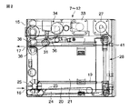
図2は、上記した各金庫部7〜12の内部構成を示すものである。
これら各金庫部7〜12は同様に構成されるため、千円金庫部7を代表して説明する。
FIG. 2 shows the internal configuration of each of the
Since each of these
図中15は金庫本体で、この金庫本体15の一側面下部側には取込返却口16が設けられ、一側面上部側には繰出口17が設けられている。金庫本体15の内部はセパレータ19によって上下に仕切られ、下部側が取込集積室20、上部側が収納室21になっている。
In the figure,
取込集積室20内には紙幣を搬送する搬送ベルト23が設けられ、この搬送ベルト23の紙幣取込側には、搬送ベルト23上に送り込まれた紙幣の後端側を跳ね上げる跳上車25が設けられ、後続して送り込まれてくる紙幣の先端部を後端側が跳ね上げられている紙幣の下部側に潜り込ませて搬送ベルト23上に集積させるようになっている。
A
また、取込集積室20内には搬送ベルト23によって取り込まれた紙幣を上方へ移送する昇降自在なバックアップとしてのバックアッププレート24が設けられている。バックアッププレート24は駆動モータ27にベルトやプーリなどから構成される動力伝達系28を介して連結され、駆動モータ27の正逆回転により昇降されるようになっている。
Further, a
また、収納室21内の上部側には、紙幣を繰り出す繰出手段としての繰出ローラ31が設けられている。繰出ローラ31は駆動モータ33にベルトやプーリなどから構成される動力伝達系34を介して連結され、駆動モータ33の回転により回転駆動されるようになっている。繰出ローラ31は第2の検出部としての検出レバーセンサ36の先端部側に取り付けられている。検出レバーセンサ36は上昇されてくる集積紙幣の上面部によって繰出ローラ31が押し上げられるのに基づいて回動することにより、紙幣の繰出位置を検出するようになっている。即ち、繰出ローラ31と検出レバーセンサ36とは繰出機構と検出機構として兼用されるようになっている。
Further, on the upper side in the
繰出ローラ31の紙幣繰出側には、分離部37が設けられている。この分離部37は送出ローラ38とこの送出ローラ38の下部側に設けられる分離ローラ39とによって構成されている。
A separation unit 37 is provided on the bill feeding side of the
また、収納室21内には、図3にも示すように上昇してくるバックアッププレート24の位置を検出する第1の検出部としての検出センサ41と、バックアッププレート24上の紙幣の有無を検出する空検出手段としての空検出センサ42が配設されている。
Further, in the
上記した検出センサ41と検出レバーセンサ36は、図4に示すようなタイミングでバックアッププレート24の位置と紙幣の繰出位置を検出するようになっている。また、検出センサ41と検出レバーセンサ36は、図5に示すように送信回路を介して算出手段43に接続され、算出手段43には測定手段44に接続されている。さらに、測定手段44には、送信回路を介して判別手段45に接続されている。また、算出手段43には送信回路を介して補正手段46が接続され、この補正手段46には送信回路を介して判別手段45が接続されている。
The
算出手段43は検出センサ41と検出レバーセンサ36の検出時間差を算出するもので、測定手段44は算出された検出時間差に基づいてバックアッププレート24上の紙幣の残量を測定するものである。判別手段45は紙幣の残量が所定量以下であるから否かを基準閾値に基づいて判別するもので、補正手段46は後で詳しく述べるように基準閾値を補正するものである。
The calculating means 43 calculates the detection time difference between the
次に、上記したように構成される紙幣処理装置の処理動作について説明する。 Next, the processing operation of the banknote processing apparatus configured as described above will be described.
(1)受付動作
客が投入排出部1から複数枚の紙幣を投入すると、この紙幣は一旦、集積部2に集積される。この集積部2に集積された紙幣は分離送出部3によって1枚ずつ分離されて搬送路4に送り出される。この送り出された紙幣は識別部5に送られてその金種等が識別されるとともに枚数が計数される。そして、この識別結果に基づいて紙幣は金種ごとの金庫部7〜12に集積される。即ち、千円は千円金庫部7の取込集積室20、五千円は五千円金庫部8の取込集積室20、一万円は一万円金庫部11の取込集積室20、二千円は二千円金庫部12に集積される。
(1) Reception operation When a customer inserts a plurality of banknotes from the insertion /
取引が確定すると、各紙幣は取込集積室20から収納室21に送り込まれて収納するされる。即ち、取込集積室20に集積された紙幣は、バックアッププレート24の上昇によりセパレータ19を通過して収納室21内に送り込まれる。こののち、バックアッププレート24は下降されてセパレータ19の下方へ復帰することにより、バックアッププレート24上の紙幣がセパレータ19上に受け取られる。以後、順次同様にして紙幣は収納室21に送り込まれて収納される。
When the transaction is confirmed, each banknote is sent from the take-up stacking
なお、上記した識別部5で判別できなかった識別エラー券は、リジェクト庫9にリジェクトされたのち、利用者に返却される。
The identification error ticket that could not be identified by the above-described
一方、収納された紙幣は、次客の取引では、釣出し用の紙幣として再利用される。 On the other hand, the stored banknote is reused as a banknote for fishing in the next customer's transaction.
(2)釣出し動作
お釣を払い出す動作では、各金庫部7〜12から必要な枚数の紙幣が繰り出される。即ち、このときには、収納室21内の集積紙幣がバックアッププレート24の上昇により押し上げられる。この集積紙幣の最上位面により繰出ローラ31が押し上げられて検出レバーセンサ36が動作すると、バックアッププレート24の上昇が停止されるとともに、繰出ローラ31の回転により紙幣が繰り出される。この繰り出される紙幣は送出ローラ38と分離ローラ39との間を通過することにより、一枚ずつ分離されて送り出される。この紙幣は搬送路4を経由して集積部2に蓄えられ、全ての釣札が集積部2に集積された後、一括して投入排出部1に排出されて釣出し動作が完了する。
(2) Unloading operation In the operation of paying out the change, a necessary number of banknotes are paid out from the respective safe units 7-12. That is, at this time, the stacked banknotes in the
上記した釣出し動作が繰り返されると、収納室21内の紙幣の残量が少なくなり、釣り札が不足であると判定される。この判定があると、高額紙幣の受付は禁止されることになる。
When the above-described fishing operation is repeated, the remaining amount of banknotes in the
次に、釣り札不足の判定方法について説明する。 Next, a method for determining the lack of fishing tags will be described.
このときには、まず、上昇するバックアッププレート24の位置が検出センサ41によって検出される。ついで、バックアッププレート24の上昇によって集積紙幣の上面部が繰出ローラ31に接触して押し上げることにより、検出レバーセンサ36が動作して集積紙幣の上面が繰出位置に到達したことが検出される。検出センサ41及び検出レバーセンサ36の検出信号は、算出手段43に送信されて検出時間差が算出される。この算出された検出時間差に基づいて測定手段44で紙幣の残量が測定され、この紙幣の残量が判別手段45で基準閾値に基づいて所定量以下であるか否かが判別される。紙幣の残量が所定量以下であると判別された場合には、釣り札が不足であるとされ、高額紙幣の受付が禁止されることになる。
At this time, first, the position of the rising
ところで、上記した検出センサ41の取付位置に誤差があったり、繰出ローラ31が磨耗した場合などには、検出センサ41と検出レバーセンサ36の検出時間差にバラツキが生じてしまう。このように検出時間差にバラツキが生じると、十分に釣り札が残っている場合でも、釣り札不足と判別して高額紙幣の受付を禁止してしまう虞がある。
By the way, when there is an error in the mounting position of the
そこで、この発明の実施の形態では、検出時間差のバラツキを考慮して基準閾値を補正するようにしている。 Therefore, in the embodiment of the present invention, the reference threshold value is corrected in consideration of variations in the detection time difference.
次に、基準閾値の補正動作について図6を参照して説明する。 Next, the reference threshold correction operation will be described with reference to FIG.
基準閾値を補正する場合には、まず、起動時の自己診断動作時、或いは、回収動作の完了時などに空検出センサ42によってバックアッププレート24上の紙幣の有無を判別する(ステップST1)。バックアッププレート24上に紙幣が有ると判別された場合には自動補正しないで終了し(ステップST2)、紙幣が無いと判別された場合には、上昇するバックアッププレート24の位置を検出センサ41によって検出し、ついで、検出レバーセンサ36によってバックアッププレート24の位置を検出する。そして、この検出時間の時間差を算出手段43で算出し(ステップST3)、この算出した検出時間差を補正手段46において、予め設定されているバックアッププレート24が空状態であの基準検出時間差(理論値)と比較してその時間差を算出する(ステップST4)。この算出された時間差分を前記基準閾値に加減算し、或いは線形補正により基準閾値を補正する(ステップST5)。判別手段45ではこの補正された閾値を用いて紙幣の残量を判別する。
When correcting the reference threshold, first, the presence or absence of banknotes on the
上記したように、この実施の形態によれば、上昇するバックアッププレート24上に紙幣が無いことを判別したのち、検出センサ41と検出レバーセンサ36によるバックアッププレート24の検出時間差を算出し、この算出した時間差と、予め設定されているバックアッププレート24が空状態での基準検出時間差(理論値)とを比較し、その時間差に基づいて基準閾値を補正するため、検出センサ41や検出レバーセンサ36に取付誤差や、経年変化があっても、バックアッププレート24上の紙幣残量を正確に判別できる。従って、従来のように、十分な釣り札枚数があるにも係わらず、高額紙幣の受け入れを中断するといったことがなく、処理効率を向上することができる利点がある。
As described above, according to this embodiment, after determining that there is no banknote on the rising
なお、この発明は、上述した実施の形態そのままに限定されるものではなく、実施段階ではその要旨を逸脱しない範囲で構成要素を変形して具体化できる。また、上述した実施の形態に開示されている複数の構成要素の適宜な組み合わせにより種々の発明を形成できる。例えば、上述した実施の形態に示される全構成要素から幾つかの構成要素を削除しても良い。更に、異なる実施の形態に亘る構成要素を適宜組み合わせても良い。 Note that the present invention is not limited to the above-described embodiment as it is, and can be embodied by modifying the constituent elements without departing from the scope of the invention in the implementation stage. Various inventions can be formed by appropriately combining a plurality of constituent elements disclosed in the above-described embodiments. For example, you may delete some components from all the components shown by embodiment mentioned above. Furthermore, you may combine the component covering different embodiment suitably.
P…紙幣(紙葉類)、24…バックアップ、31…繰出ローラ(繰出手段)、36…検出レバーセンサ(第2の検出部)、41…検出センサ(第1の検出部)、42…空検出手段、43…算出手段、44…測定手段、45…判別手段、46…補正手段。 P ... bills (paper sheets), 24 ... backup, 31 ... feeding roller (feeding means), 36 ... detection lever sensor (second detection unit), 41 ... detection sensor (first detection unit), 42 ... empty Detection means, 43 ... calculation means, 44 ... measurement means, 45 ... discrimination means, 46 ... correction means.
Claims (4)
このバックアップによって上昇されてくる積層紙葉類をその最上位の紙葉類から繰出す繰出手段と、
前記上昇するバックアッププレートの位置を検出する第1の検出部、及び前記繰出手段に到達した前記紙葉類の位置を検出する第2の検出部と、
前記第1及び第2の検出部の検出時間差を算出する算出手段と、
この算出手段によって算出された検出時間差に基づいて前記紙葉類の残量を測定する測定手段と、
この測定手段によって測定された残量が所定量以下であるか否かを基準閾値を用いて判別する判別手段と、
前記紙葉類が存在しない空の状態で上昇する前記バックアップを前記第1の検出部と前記第2の検出部によって検出してその検出時間差を算出し、この算出した検出時間差と予め設定されている前記バックアップが空状態での基準時間差とを比較し、その時間差分に基づいて前記基準閾値を補正する補正手段と
を具備することを特徴とする紙葉類処理装置。 A backup for placing paper sheets in a stacked state and raising them along the stacking direction;
A feeding means for feeding the laminated paper sheets raised by the backup from the uppermost paper sheet;
A first detection unit that detects the position of the rising backup plate, and a second detection unit that detects the position of the paper sheet that has reached the feeding means;
Calculating means for calculating a detection time difference between the first and second detection units;
Measuring means for measuring the remaining amount of the paper sheet based on the detection time difference calculated by the calculating means;
Discriminating means for discriminating whether or not the remaining amount measured by the measuring means is equal to or less than a predetermined amount using a reference threshold;
Calculates the detection time difference detecting said backup to rise in an empty state in which the paper sheet is not present by the second detector and the first detector, is pre-set to detect the time difference and the calculated said backup there are compared with the reference time difference in the empty state, the paper sheet processing apparatus characterized by comprising a correction means for correcting the reference threshold on the basis of the time difference amount.
Priority Applications (1)
| Application Number | Priority Date | Filing Date | Title |
|---|---|---|---|
| JP2006268810A JP4965954B2 (en) | 2006-09-29 | 2006-09-29 | Paper sheet processing equipment |
Applications Claiming Priority (1)
| Application Number | Priority Date | Filing Date | Title |
|---|---|---|---|
| JP2006268810A JP4965954B2 (en) | 2006-09-29 | 2006-09-29 | Paper sheet processing equipment |
Publications (2)
| Publication Number | Publication Date |
|---|---|
| JP2008090476A JP2008090476A (en) | 2008-04-17 |
| JP4965954B2 true JP4965954B2 (en) | 2012-07-04 |
Family
ID=39374577
Family Applications (1)
| Application Number | Title | Priority Date | Filing Date |
|---|---|---|---|
| JP2006268810A Active JP4965954B2 (en) | 2006-09-29 | 2006-09-29 | Paper sheet processing equipment |
Country Status (1)
| Country | Link |
|---|---|
| JP (1) | JP4965954B2 (en) |
Cited By (1)
| Publication number | Priority date | Publication date | Assignee | Title |
|---|---|---|---|---|
| CN107665540A (en) * | 2016-07-28 | 2018-02-06 | 光荣株式会社 | Paper processing device |
Family Cites Families (3)
| Publication number | Priority date | Publication date | Assignee | Title |
|---|---|---|---|---|
| JPS6322435A (en) * | 1986-07-14 | 1988-01-29 | Hitachi Ltd | Paper handling device |
| JP4044281B2 (en) * | 2000-12-21 | 2008-02-06 | 日立オムロンターミナルソリューションズ株式会社 | Banknote handling equipment |
| JP2006024032A (en) * | 2004-07-08 | 2006-01-26 | Toshiba Corp | Paper sheet processor |
-
2006
- 2006-09-29 JP JP2006268810A patent/JP4965954B2/en active Active
Cited By (1)
| Publication number | Priority date | Publication date | Assignee | Title |
|---|---|---|---|---|
| CN107665540A (en) * | 2016-07-28 | 2018-02-06 | 光荣株式会社 | Paper processing device |
Also Published As
| Publication number | Publication date |
|---|---|
| JP2008090476A (en) | 2008-04-17 |
Similar Documents
| Publication | Publication Date | Title |
|---|---|---|
| JP5060019B2 (en) | Header card processing system | |
| JP5633456B2 (en) | Banknote deposit and withdrawal machine | |
| JP5337524B2 (en) | Paper sheet processing equipment | |
| WO2016093218A1 (en) | Paper sheet processing device | |
| CN108475454B (en) | Paper money processing device and method | |
| JP2015049874A (en) | Paper sheet processing system and paper sheet processing method | |
| JP6552989B2 (en) | Sealing device and sealing method | |
| JP2007210718A (en) | Paper handling device and its maintenance system | |
| JP4965954B2 (en) | Paper sheet processing equipment | |
| TWI708218B (en) | A paper sheet processing apparatus | |
| JPS62236094A (en) | Abnormality processing system for sheet paper handler | |
| JP3931165B2 (en) | Paper sheet handling equipment | |
| JP2000057402A (en) | Sealed small wad management device | |
| JP7290250B2 (en) | Banknote processing equipment | |
| JP5386326B2 (en) | Banknote handling machine | |
| JPH06103438A (en) | Paper money processing machine | |
| JP4544946B2 (en) | Coin processing equipment | |
| JP5868792B2 (en) | Banknote handling equipment | |
| JP2680486B2 (en) | Banknote counting machine | |
| JP3837233B2 (en) | Money handling equipment | |
| US20220383688A1 (en) | Coin deposit processor | |
| JP2007140939A (en) | Paper sheet processor | |
| JP6531038B2 (en) | Medium identification device and medium identification method | |
| JP4695405B2 (en) | Paper sheet processing equipment | |
| JP4501629B2 (en) | Coin deposit / withdrawal device |
Legal Events
| Date | Code | Title | Description |
|---|---|---|---|
| A621 | Written request for application examination |
Free format text: JAPANESE INTERMEDIATE CODE: A621 Effective date: 20090209 |
|
| A977 | Report on retrieval |
Free format text: JAPANESE INTERMEDIATE CODE: A971007 Effective date: 20111122 |
|
| A131 | Notification of reasons for refusal |
Free format text: JAPANESE INTERMEDIATE CODE: A131 Effective date: 20111213 |
|
| A521 | Written amendment |
Free format text: JAPANESE INTERMEDIATE CODE: A523 Effective date: 20120213 |
|
| TRDD | Decision of grant or rejection written | ||
| A01 | Written decision to grant a patent or to grant a registration (utility model) |
Free format text: JAPANESE INTERMEDIATE CODE: A01 Effective date: 20120306 |
|
| A01 | Written decision to grant a patent or to grant a registration (utility model) |
Free format text: JAPANESE INTERMEDIATE CODE: A01 |
|
| A61 | First payment of annual fees (during grant procedure) |
Free format text: JAPANESE INTERMEDIATE CODE: A61 Effective date: 20120330 |
|
| R151 | Written notification of patent or utility model registration |
Ref document number: 4965954 Country of ref document: JP Free format text: JAPANESE INTERMEDIATE CODE: R151 |
|
| FPAY | Renewal fee payment (event date is renewal date of database) |
Free format text: PAYMENT UNTIL: 20150406 Year of fee payment: 3 |