JP4041954B2 - Printing control apparatus, printing control method, printing system, and printing control program - Google Patents
Printing control apparatus, printing control method, printing system, and printing control program Download PDFInfo
- Publication number
- JP4041954B2 JP4041954B2 JP2002100199A JP2002100199A JP4041954B2 JP 4041954 B2 JP4041954 B2 JP 4041954B2 JP 2002100199 A JP2002100199 A JP 2002100199A JP 2002100199 A JP2002100199 A JP 2002100199A JP 4041954 B2 JP4041954 B2 JP 4041954B2
- Authority
- JP
- Japan
- Prior art keywords
- data
- gradation
- printing
- error
- Prior art date
- Legal status (The legal status is an assumption and is not a legal conclusion. Google has not performed a legal analysis and makes no representation as to the accuracy of the status listed.)
- Expired - Fee Related
Links
Images


Description
【0001】
【発明の属する技術分野】
本発明は、印刷データを構成する画素別の階調データに対応して印刷媒体上にインクのドットを形成する印刷装置に対し、印刷制御を行う印刷制御装置、印刷制御方法、印刷システム、印刷制御プログラムおよび印刷制御プログラムを記録した媒体に関する。
【0002】
【従来の技術】
従来、この種の印刷制御装置は、数色のインクを印刷ヘッドから印刷用紙上に吐出するカラープリンタに対して、画素別の階調データで構成した印刷データを生成することにより印刷制御を行っている。ここで、良好な色精度を得て高画質化を図るため、印刷ヘッドの製造ばらつきに伴うインク吐出量の誤差を印刷ヘッド毎に補償することが提案されている。その際、インクの種類別とされた誤差情報であるカラー調整IDをプリンタに記憶させておき、同カラー調整IDをプリンタから受信してカラー調整IDに応じた係数を階調データに乗じることにより、インクの色別にインク量の誤差を補償する。
【0003】
【発明が解決しようとする課題】
上述した従来の技術においては、印刷された画像のある濃度領域において思い通りの色が十分には再現されていないと感じられることがあった。そこで、さらに色精度を向上させて思い通りの印刷をさせたいという希望があった。
本発明は、上記課題にかんがみてなされたもので、色精度を向上させ、印刷物をより高画質化させることが可能な印刷制御装置、印刷制御方法、印刷システム、印刷制御プログラムおよび印刷制御プログラムを記録した媒体の提供を目的とする。
【0004】
【課題を解決するための手段】
上記目的を達成するため、請求項1にかかる発明は、印刷データを構成する画素別の階調データに対応して印刷媒体上にインクのドットを形成する印刷装置に対し、印刷制御を行う印刷制御装置であって、上記インクのインク重量の誤差を表すとともに複数段階の階調データに対応した複数の誤差情報を取得する誤差取得手段と、画像を表現する画像データを入力し、上記誤差取得手段にて取得された複数の誤差情報に基づいて同画像データから上記インク重量の誤差を補償させる上記印刷データを生成し、上記印刷制御を行う印刷制御手段とを具備し、上記複数の誤差情報は、上記階調データのとりうる階調領域内で異なる値とされた複数段階の基準階調値に対応する情報とされるとともに、同基準階調値は、大きい値から小さい値の順番にしたときに略2分の1ずつ小さくなるようにされている構成としてある。
【0005】
すなわち、誤差取得手段が取得する複数の誤差情報は、インクのインク重量の誤差を表すとともに複数段階の階調データに対応した情報である。印刷制御手段により生成される印刷データは、複数段階の階調データに対応した複数の誤差情報に基づいて画像データからインク重量の誤差を補償させるように生成されたデータとなる。その結果、印刷装置は、複数段階の階調データに対応した複数の誤差情報が反映された印刷データに基づいてきめ細やかな誤差補償をインク重量の誤差に対して行いながら印刷媒体上にインクのドットを形成する。
従って、印刷媒体上に現れる色精度を向上させることが可能となり、印刷物はより高画質化される。
なお、インクの色は複数あってもよいし、一つであってもよい。
また、上記誤差取得手段にて取得された複数の誤差情報に基づいて、修正前の階調データと上記インク重量の誤差を補償させる修正後の階調データとの対応関係を同複数の誤差情報のそれぞれについて決定する対応関係決定手段が設けられ、上記印刷制御手段は、上記決定された複数の誤差情報のそれぞれについての対応関係に基づいて上記画像データから上記印刷データを生成し、上記印刷制御を行う構成としてもよい。すなわち、対応関係決定手段は、同複数の誤差情報に基づいて、修正前の階調データとインク重量の誤差を補償させる修正後の階調データとの対応関係を同複数の誤差情報のそれぞれについて決定する。すると、印刷制御手段により生成される印刷データは、複数段階の階調データに対応した複数の誤差情報のそれぞれについて決定された対応関係に基づくデータとなる。その結果、印刷装置は、複数段階の階調データに対応した複数の誤差情報が反映された印刷データに基づいてきめ細やかな誤差補償をインク重量の誤差に対して行いながら印刷媒体上にインクのドットを形成する。
【0006】
印刷装置が複数の誤差情報を記憶している場合、誤差取得手段は、印刷装置から複数の誤差情報を取得してもよい。誤差情報が印刷装置と一体となっているので、本印刷制御装置のユーザは印刷装置を変更しても誤差情報が印刷装置から取得されることにより別途誤差情報を入力する必要がない。
また、誤差取得手段は、基準階調値のいずれかを中心として異ならせた複数の階調値に対応する複数の基準画像を印刷装置に印刷させ、印刷された複数の基準画像のいずれかに対応する階調値を同中心とした基準階調値に対応する誤差情報として取得してもよい。すなわち、複数の誤差情報は、基準階調値のいずれかを中心として異ならせた複数の階調値に対応する複数の基準画像のいずれかに相当する階調値とされる。
このように、誤差情報を取得する構成の具体例は様々考えられるが、これら以外にも、例えば、本印刷制御装置が誤差情報を記憶していてもよいし、他のコンピュータから誤差情報を入手してもよい。
【0007】
なお、対応関係決定手段は、修正前の階調データのうち基準階調値以外の階調値についての対応関係を基準階調値および複数の誤差情報から線形補間演算を行うことにより決定してもよい。すなわち、修正前後の階調データの対応関係は、基準階調値と複数の誤差情報とから簡易な演算で決定される。
【0008】
印刷制御手段が色変換テーブルを参照して同画像データを同印刷データに変換する場合、対応関係決定手段は、複数の誤差情報のそれぞれについての対応関係に基づいて色変換テーブルを修正してもよい。複数の誤差情報が反映された色変換テーブルを使用することにより、画像データは修正後の印刷データまで一気に変換される。
【0009】
印刷装置が当該印刷装置を識別可能な識別データを記憶している場合、対応関係決定手段は、印刷装置から識別データを取得して上記修正された色変換テーブルと対応させて記憶可能であり、取得した識別データが同記憶された識別データとは異なるとき、誤差取得手段に複数の誤差情報を取得させ、取得された複数の誤差情報に基づいて修正前後の階調データの対応関係を決定し、同複数の誤差情報のそれぞれについての対応関係に基づいて色変換テーブルを修正してもよい。すなわち、印刷装置から取得した識別データが記憶した識別データと違うときにのみ、色変換テーブルが修正される。
【0010】
印刷データがインク重量の異なる複数種類のドットの形成をまとめて表現する階調データから構成され、印刷装置が画素別にドットの種類を表現するドットデータに対応してインク重量の異なる複数種類のドットを印刷媒体上に形成可能である場合、印刷制御手段は、画像データから印刷データに変換するとともに、当該印刷データとドットデータとの対応関係を複数種類のドット別に規定したドット形成テーブルを参照して同印刷データを同ドットデータに変換すればよい。この場合、対応関係決定手段は、複数の誤差情報のそれぞれについての対応関係に基づいてドット形成テーブルを修正してもよい。すなわち、複数の誤差情報が反映されたドット形成テーブルを使用することにより、印刷データは修正後のドットデータまで一気に変換される。
このように、対応関係決定手段の構成は、様々考えられるが、これらの構成以外にも、例えば、複数の誤差情報のそれぞれに対応して階調データを帯域別に分けておき、画像データを修正前の印刷データに変換した後、帯域別に複数の誤差情報に基づく帯域別の補正係数を乗じて修正後の印刷データに変換してもよい。
【0011】
上記複数の誤差情報は、上記階調データのとりうる階調領域内で異なる値とされた複数段階の基準階調値に対応する情報とされるとともに、同基準階調値は、大きい値から小さい値の順番にしたときに略2分の1ずつ小さくなるようにされている。印刷ヘッドの駆動周波数は高階調領域から低階調領域になるにつれ2分の1ずつ段階的に小さくなり、インク重量の誤差量は同駆動周波数に応じた誤差量となりやすい。そこで、基準階調値を2分の1ずつ段階的に小さくすることにより、色精度をより向上させることができる。
【0012】
ところで、上述した印刷制御装置は、単独で実施される場合もあるし、ある機器に組み込まれた状態で他の方法とともに実施されることもあるなど、発明の思想としては各種の態様を含むものであって、適宜、変更可能である。
また、上述した印刷制御を行う際の手法は、所定の手順に従って処理を進めていくうえで、その根底にはその手順に発明が存在するということは当然である。従って、本発明は方法としても適用可能であり、請求項9にかかる発明においても、基本的には同様の作用となる。
さらに、印刷データを生成して印刷を行う印刷手段を備える印刷システムとしても適用可能であり、請求項10にかかる発明においても、基本的には同様の作用となる。
【0013】
本発明を実施しようとする際に、印刷制御装置にて所定のプログラムを実行させる場合もある。さらに、同プログラムを記録した媒体が流通し、同記録媒体からプログラムを適宜コンピュータに読み込むことが考えられる。そこで、そのプログラムやプログラムを記録したコンピュータ読み取り可能な記録媒体としても適用可能であり、請求項11にかかる発明においても、基本的には同様の作用となる。
むろん、請求項2〜請求項8に記載された構成を上記方法や印刷システムやプログラムやプログラムを記録した媒体に対応させることも可能であることは言うまでもない。
ここで、上記記録媒体は、磁気記録媒体や光磁気記録媒体の他、今後開発されるいかなる記録媒体であってもよい。また、一部がソフトウェアであって、一部がハードウェアで実現される場合においても本発明の思想において全く異なるものではなく、一部を記録媒体上に記録しておいて必要に応じて適宜読み込む形態のものも含まれる。さらに、一次複製品、二次複製品などの複製段階については全く問う余地なく同等である。
【0014】
【発明の効果】
以上説明したように、請求項1、請求項2、請求項9〜請求項11にかかる発明によれば、色精度を向上させ、印刷物をより高画質化させることが可能となる。
請求項3にかかる発明によれば、印刷装置に記憶された情報をそのまま取得するという簡易な構成で複数の誤差情報を取得することができ、印刷装置を変更しても別途誤差情報を入力する必要がなく、利便性が向上する。
請求項4にかかる発明によれば、印刷される複数の基準画像を利用して複数の誤差情報を取得することができる。
請求項5にかかる発明によれば、簡易な構成で修正前後の階調データの対応関係を決定することができる。
【0015】
請求項6にかかる発明によれば、画像データから印刷データへの変換処理を高速化させることができる。
請求項7にかかる発明によれば、色変換テーブルが修正される頻度が少なくなるので、印刷制御の処理を高速化させることができる。
請求項8にかかる発明によれば、印刷データからドットデータへの変換処理を高速化させることができる。
【0016】
【発明の実施の形態】
以下、下記の順序に従って本発明の実施形態を説明する。
(1)印刷システムの構成:
(2)印刷制御装置の概略構成:
(3)印刷制御装置が行う処理:
(4)第二の実施形態:
(5)第三の実施形態:
(6)第四の実施形態:
【0017】
(1)印刷システムの構成:
図1は、本発明の第一の実施形態にかかる印刷制御装置と周辺装置とからなる印刷システムの概略構成を示している。本印刷システムは、本発明にいう印刷制御装置となるパーソナルコンピュータ(PC)10、印刷装置であるカラー印刷可能なインクジェットプリンタ20等から構成されている。
PC10は演算処理の中枢をなすCPU11を備えており、このCPU11はシステムバス10aを介してPC10全体の制御を行う。同バス10aには、ROM12、RAM13、CD−ROMドライブ15、フレキシブルディスク(FD)ドライブ16、各種インターフェイス(I/F)17a〜e等が接続されている。また、ハードディスクドライブを介してハードディスク(HD)14も接続されている。本実施形態のコンピュータにはデスクトップ型PCを採用しているが、コンピュータとしては一般的な構成を有するものを採用可能である。
【0018】
HD14には、ソフトウェアとしてオペレーティングシステム(OS)や画像情報等を作成可能なアプリケーションプログラム(APL)等が格納されており、これらのソフトウェアは、実行時にCPU11によって適宜RAM13に転送される。そして、CPU11は、RAM13を一時的なワークエリアとして適宜アクセスしながら種々のプログラムを実行する。
USBI/F17aには、カラー測色器30や、図示しないカラースキャナ、デジタルカメラ等が接続されるようになっている。カラー測色器30は、測色する対象に色検出部30aを向けることにより、Lab表色系に基づく測色値、すなわち、明度を表すL値と、色相および彩度を表すa値およびb値を計測可能である。測色器30にて計測されたLab値は、USBI/F17aを介して読み込むことが可能である。むろん、測色器とPC10との接続には、RS−232C接続等、他の接続態様も採用可能である。
CRTI/F17bにはカラー画像データに基づく画像を表示するディスプレイ18aが接続され、入力I/F17cにはキーボード18bやマウス18cが操作用入力機器として接続されている。また、プリンタI/F17eには、パラレルI/Fケーブルを介してプリンタ20が接続されている。むろん、プリンタ20との接続には、シリアルI/FやSCSI、USB接続など種々の接続態様を採用可能である。
【0019】
プリンタ20は、C(シアン)、M(マゼンタ)、Y(イエロー)、K(ブラック)、Lc(ライトシアン)、Lm(ライトマゼンタ)のインクを使用して、印刷用紙(印刷媒体)に対して印刷データを構成する階調データに対応したインク量となるようにインクを吐出し、画像を印刷する。むろん、6色以外のインクを使用するプリンタを採用してもよい。また、インク通路内に泡を発生させてインクを吐出するバブル方式のプリンタや、レーザープリンタ等、種々の印刷装置を採用可能である。
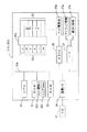
図2に示すように、プリンタ20では、CPU21、ROM22、RAM23、通信I/O24、ASIC26、I/F27、等がバス20aを介して接続されている。
【0020】
通信I/O24はPC10のプリンタI/F17eと接続されており、プリンタ20は通信I/O24を介してPC10から送信されるCMYKLcLmに変換された画像のデータやページ記述言語等からなる印刷ジョブを受信する。カートリッジホルダ25aにはCMYKLcLmのインクカートリッジ25bが装着されており、インクカートリッジ25b内の各色インクが色別に印刷ヘッド25に供給されるようになっている。ASIC26は、CPU21と所定の信号を送受信しつつヘッド駆動部26aに対してCMYKLcLmデータに基づく印加電圧データを出力する。同ヘッド駆動部26aは、同印加電圧データに基づいて印刷ヘッド25に内蔵されたピエゾ素子への印加電圧パターンを生成し、印刷ヘッド25に6色のインクをドット単位で吐出させる。印刷ヘッド25のインク吐出面には、6色のインクを吐出する6組のノズル列が印刷ヘッドの主走査方向に並ぶように形成され、ノズル列のそれぞれは複数のノズルが副走査方向に一定の間隔で直線状に配置されている。
【0021】
ここで、ASIC26は、CMYKLcLmデータが高階調領域、すなわち、使用するインク量が多くてほとんどの画素でドットを形成する領域であるときには高周波の駆動周波数(周波数をfとする)が印刷ヘッド25に供給されるように印加電圧データを生成する。CMYKLcLmデータが高階調領域よりも一段階低い中間階調領域(使用するインク量が中程度)であるときには周波数がより低いf/2の駆動周波数が印刷ヘッド25に供給されるように印加電圧データを生成する。CMYKLcLmデータがさらに一段階低い低階調領域(使用するインク量が少)であるときにはf/4の駆動周波数が印刷ヘッド25に供給されるように印加電圧データを生成する。従って、ヘッド駆動部26aは、CMYKLcLmデータが高階調領域から低階調領域になるにつれ2分の1ずつ段階的に低くなる駆動周波数の印加電圧パターンを生成する。
I/F27に接続されたキャリッジ機構27aや紙送り機構27bは、印刷ヘッド25を主走査させたり、適宜改ページ動作を行いながら印刷用紙を順次送り出して副走査を行ったりする。そして、CPU21が、RAM23をワークエリアとして利用しながらROM22に書き込まれたプログラムに従って各部を制御する。
【0022】
印刷ヘッド25に設けられている各ノズル毎に、電歪素子の一つであって応答性に優れたピエゾ素子が配置されている。図3は、ピエゾ素子PEとノズルNzとの構造を断面視して示している。図の上段に示すように、ピエゾ素子PEは、ノズルNzまでインクを導くインク通路25cに接する位置に設置されている。なお、インク通路25cにはインクが満たされているのものとしてハッチングを付している。ピエゾ素子PEは、電圧の印加により結晶構造が歪み、極めて高速に電気−機械エネルギーの変換を行う素子である。本実施形態では、ピエゾ素子PEの両端に設けられた電極間に所定時間幅の電圧を印加することにより、図の下段に示すように、ピエゾ素子PEが電圧の印加時間だけ伸張し、インク通路25cの一側壁を変形させる。この結果、インク通路25cの体積はピエゾ素子PEの伸張に応じて収縮し、この収縮分に相当するインクが、インク滴Ipとなって、ノズルNzの先端から高速に吐出される。このインク滴Ipが印刷用紙に染み込むことにより印刷が行われる。
【0023】
ここで、インク滴Ipの大きさは、インク通路25cの製造誤差やピエゾ素子PEの個体差に起因しても変動する。この変動量が、誤差情報である複数のカラー調整ID22aとしてROM22の所定領域に格納されている。むろん、印刷ヘッド25を有する印刷ヘッドユニットに不揮発性メモリを設け、この不揮発性メモリにカラー調整IDを格納するようにしてもよい。図4に模式的に示すように、複数のカラー調整ID22aは、インクの色別、かつ、印刷データを構成する階調データのとりうる階調領域内で異なる値とされた3段階の基準階調値(複数段階の階調データ)別に設けられている。図のカラー調整ID22aは、基準階調値63,127,255に対応してID1(低階調用)、ID2(中階調用)、ID3(高階調用)から構成されている。カラー調整ID22aは、以下のようにして決定され、ROM22に書き込まれるようになっている。
【0024】
すなわち、色別に各基準階調値で実際に使用されるインクの重量を測定し、プリンタ標準機で使用されるインクの重量(仕様値)を50としたときの相対値をカラー調整IDとする。図の下段は、仕様値を基準として、測定したインク重量の相対値を棒グラフとして表している。例えば、基準階調値63のときのインク重量の仕様値が1890ngであり、実際に使用されるインク重量が2190ngであるとき、カラー調整IDとして記憶される値は、2190÷1890×50=58(小数点以下四捨五入)となる。本プリンタ20は6色のインクを使用し、基準階調値として3段階設けているので、6×3=18のカラー調整IDをROM22に書き込むことになる。そして、カラー調整IDで表されるインクの変動量を色別かつ各階調段階毎に補償して正確な色再現を行う。
【0025】
なお、上述したように印刷ヘッド25の駆動周波数はCMYKLcLmデータが高階調領域から低階調領域になるにつれ2分の1ずつ段階的に小さくなるので、インク量の誤差量はCMYKLcLmデータのとりうる階調領域内で段階的に変動する傾向がある。そこで、基準階調値を大きい値から小さい値の順番に255,127,63と略2分の1ずつ小さくなるようにして、色精度をより向上させるようにしている。
また、ROM22には、プリンタ20を個別に識別可能とするためプリンタ20毎に異なるデータとされた識別データであるシリアルナンバー(シリアルNo)22bも格納されている。そして、プリンタ20は、通信I/O24を介してPC10からカラー調整IDやシリアルNoの入手要求を受信すると、ROM22からカラー調整IDやシリアルNoを読み出してPC10に送信する処理を行うようになっている。
【0026】
PC10では、以上のハードウェアを基礎としてバイオスが実行され、その上層にてOSとAPLとが実行される。OSには、プリンタI/F17eを制御するプリンタドライバ等の各種のドライバ類が組み込まれ、OSの一部となってハードウェアの制御を実行する。プリンタドライバは、プリンタI/F17eを介してプリンタ20と双方向の通信を行うことが可能であり、GDI(Graphics Device Interface )等が組み込まれたOSを介してAPLから画像データを受け取って印刷ジョブを作成し、プリンタ20に送出する。そして、本発明の印刷制御プログラムは、同プリンタドライバから構成される。むろん、APLにより構成することも可能である。また、HD14は同プログラムを記録した媒体であるが、同媒体は、例えば、CD−ROM、FD16a、光磁気ディスク、不揮発性メモリ、パンチカード、バーコード等の符号が印刷された印刷媒体、等であってもよい。むろん、モデム等の通信I/F17dをインターネット網に接続し、所定のサーバにアクセスして本印刷制御プログラムをダウンロードして実行させることも可能である。
【0027】
HD14には、変換前のR(赤)、G(緑)、B(青)の3要素色から画像を表現するRGBデータ(画像データ)を構成する階調データと、変換後のCMYKLcLmの6要素色からなるCMYKLcLmデータ(印刷データ)を構成する階調データと、の対応関係を複数の参照点について規定したルックアップテーブルと呼ばれるLUT(色変換テーブル)が記憶されている。このLUTは、プリンタ標準機のインク量に対応したテーブルとされている。プリンタドライバは、LUTを参照してRGBデータを印刷データに変換し、プリンタ20に対して印刷制御を行う。
【0028】
(2)印刷制御装置の概略構成:
図5は、上記ハードウェアと上記印刷制御プログラムとが協働して構築する印刷制御装置の構成を模式的に示している。印刷制御プログラムは複数のモジュールから構成されており、同モジュールはPC10に誤差取得機能、対応関係決定機能、印刷制御機能を実現させる。そして、これらの機能に対応して各種手段U1〜U3が構成される。
【0029】
誤差取得手段U1は、プリンタ20から複数のカラー調整IDをそのまま取得するという簡易な構成とされている。対応関係決定手段U2は、取得された複数のカラー調整IDに基づいて、修正前の階調データとインク量の誤差を補償させる修正後の階調データとの対応関係を、インクの色別、かつ、複数段階とされた基準階調値に対応したカラー調整IDのそれぞれについて決定する。本実施形態では、カラー調整IDの値をID、修正前の階調値をX、修正後の階調値をYで表すと、修正前の階調データのうち基準階調値については、以下の式により修正後の階調値を決定する。
Y = X × 50 / ID ・・・(1)
このようにして決定される基準階調値の対応関係の一例を、図6の上段に示している。図は、6色のインクのうちのいずれか(図の例はシアン)に相当する基準階調値の修正前後の対応関係のデータが格納された対応関係テーブルT1を示したものである。すなわち、対応関係テーブルT1は、CMYKLcLmの色別に作成されることになる。
なお、修正前の階調値0は、修正後の階調値0に対応させるものとする。
【0030】
また、図の下段に示すように、修正前の階調データのうち基準階調値以外の階調値についての修正後の階調値は、基準階調値とカラー調整IDとから線形補間演算を行うことにより決定する。図は、6色のインクのうちのいずれかに相当する階調データの修正前後の対応関係をグラフ形式で示したものであり、横軸が修正前の階調値、縦軸が修正後の階調値となっている。ここで、補間演算に使用する二つの修正前の基準階調値または階調値0をX1,X2(X1<X2)、同補間演算に使用する二つの修正前の階調値X1,X2に対応する修正後の階調値をY1,Y2(Y1<Y2)とすると、修正前の階調値Xに対応する修正後の階調値Yを、以下の式により算出する。
【数1】

このように、線形補間演算とすることにより簡易かつ高速な処理にて修正前後の階調データの全階調領域の対応関係を決定することができるが、使用環境に応じて、曲線状とする補間演算を行ってきめ細やかに修正前後の階調データの対応関係を決定してもよい。
【0031】
本実施形態では、決定した対応関係に基づいて、プリンタ標準機用のLUTから修正されたLUTを生成することにしている。印刷制御手段U3は、画像データを入力し、複数段階とされた基準階調値に対応したカラー調整IDのそれぞれについて決定された対応関係が反映されたLUTを参照して画像データを印刷データに変換し、プリンタ20に対して印刷制御を行う。このように、複数のカラー調整IDが反映されたLUTを使用することにより、画像データは修正後の印刷データまで一気に変換されるので、変換処理を高速化させることができる。そして、生成される印刷データは、複数段階の階調データに対応した複数の誤差情報のそれぞれについて決定された対応関係に基づいて修正されたデータとなるため、カラー調整IDをインクの種類別に一つだけ用意していた従来と比べ、プリンタ20はよりきめ細やかな誤差補償をインク量の誤差に対して行いながら印刷媒体上にインクのドットを形成する。
【0032】
印刷制御手段U3は、図示しない解像度変換部、色変換部、ハーフトーン処理、ラスタライズ処理部を備える。
解像度変換部では、画像データを入力し、プリンタ20の解像度に合わせて同画像データの解像度を変換する。入力する画像データは、画像をドットマトリクス状の多数の画素で階調表現したデータであり、様々な種類がある。例えば、sRGB色空間で定義されるRGBから構成された画像データや、YUV表色系における輝度(Y成分)、Bの色差(U成分)、Rの色差(V成分)から構成された画像データ等がある。また、画像データの各成分も様々な階調数とされており、例えば、256階調、1024階調等がある。そこで、sRGBやYUV表色系等の定義に従って、画像データを広域RGB色空間内のRGB各256階調(0〜255の整数値)のRGBデータに変換する。
【0033】
色変換部では、RGBデータを構成する各画素の階調データを変換対象として順次対象画素を移動させながら、修正されたLUTを参照してRGBデータをCMYKLcLmインクのそれぞれの使用量に対応した階調データからなるCMYKLcLmデータに色変換する。CMYKLcLmデータもCMYKLcLm各256階調(0〜255の整数値)のデータとされている。図5に示すように、LUTはCMYKLcLm別に階調データが格納されてHD14に記憶されており、補間演算を前提として、例えばRGB各17すなわち17の3乗個の格子点に対応した大量のデータを備えている。図では、わかりやすく説明するためLUT中にRGBデータを示しているが、実際にはRGBデータを構成する各階調データに対応するアドレスからCMYKLcLm48ビット分のデータを参照することにより、RGBデータをCMYKLcLmデータに変換するようになっている。なお、入力するRGBデータに一致するCMYKLcLmデータがLUTに格納されていない場合には、入力するRGBデータに近い複数のRGBデータに対応するCMYKLcLmデータを取得し、体積補間等の補間演算によりCMYKLcLmデータを算出する。
【0034】
ハーフトーン処理部では、誤差拡散法等によるハーフトーン処理を行い、256階調のCMYKLcLmデータをプリンタ20の印刷ドットに対応する2階調に変換する。そして、ラスタライズ処理部では、プリンタの印刷ヘッド25の走査幅に基づいて2階調とされたCMYKLcLmデータのビットデータを並べ替えるラスタライズ処理を行い、処理後のCMYKLcLmデータをプリンタ20に対して出力する。CMYKLcLmデータはCMYKLcLmのインク使用量のデータであり、プリンタ20は、印刷データであるCMYKLcLmデータを入手して対応するインクをメディア上に吐出させると、印刷データに基づく画像を印刷することができる。このようにして、プリンタ20に対して印刷制御を行うことができる。そして、印刷制御手段U3とプリンタ20とから印刷手段が構成される。
なお、ハーフトーン処理やラスタライズ処理を実行可能なプリンタに対してCMYKLcLmデータを出力する際には、これらの処理を行わずにCMYKLcLmデータをプリンタに対して出力することができる。
【0035】
(3)印刷制御装置が行う処理:
図7は、本印刷制御装置が行う修正LUT作成処理をフローチャートにより示している。本フローは、プリンタ20用のプリンタドライバがインストールされるときに行われる。
まず、誤差取得手段により、カラー調整IDの入手要求を作成してプリンタ20に送信する(ステップS105。以下、「ステップ」の記載を省略)。すると、プリンタ20は同入手要求を受信し、ROM22からカラー調整IDのID1〜3全てを読み出してPC10に対して送信する。そこで、PC10では、同カラー調整IDのID1〜3を取得し、HD14の所定領域に格納する(S110)。このように、カラー調整IDがプリンタと一体となっているので、本印刷システムのユーザはプリンタを変更しても別途カラー調整IDを入力する必要がなく、本印刷制御装置は便利である。
【0036】
次に、対応関係決定手段により、修正前の階調データとインク量の誤差を補償させる修正後の階調データとの対応関係を、インクの色別、かつ、基準階調値別に決定する(S115)。ここでは、上記演算式(1)を用いて色別の基準階調値の修正前後の対応関係データを決定して、図6の上段で示したような対応関係テーブルT1を作成する。
その後、プリンタ標準機用のLUTをHDから読み出す(S120)。同LUTには修正前となるCMYKLcLmの階調値が格納されているので、上記対応関係テーブルT1を参照し、線形補間演算用の演算式(2)を用いてCMYKLcLmの階調値を修正する(S125)。演算式(2)の演算結果が255よりも大きいときには、階調値255に置き換える。すると、図6の下段で示した対応関係となるように階調データの全階調領域について修正後の階調値を決定することができる。
【0037】
そして、補間演算により修正した各階調値を図5で示した修正LUTとしてHDの所定領域に記憶させ(S130)、本フローを終了する。ここで、修正LUTに格納されたCMYKLcLmの階調値は複数段階の基準階調値に対応した複数のカラー調整IDが反映されているので、同修正LUTは、画像を画素別の階調データで構成した画像データと、インク量の誤差をきめ細やかに補償させる修正後の階調データで構成した印刷データとの対応関係を複数の参照点について規定するテーブルとなる。
【0038】
修正LUTが作成されると、この修正LUTを使用してプリンタ20に印刷させる制御を行うことができる。図8は、印刷制御手段により行われる印刷制御処理をフローチャートにより示している。
APLはAPL用印刷機能を有しており、このAPL用印刷機能にてディスプレイ18aに表示される印刷実行メニューが選択されると、本フローを開始する。まず、印刷させる画像を表現する画像データを入力する(S205)。入力する画像データは、図示しないデジタルカメラやスキャナ等にて取り込まれた画像のデータや、FD16a等に記録した画像データ等がある。なお、データ全体を一括して読み込む必要はなく、部分的に読み込むようにしてもよいし、データの受け渡しに利用されるバッファ領域を表すポインタの受け渡しだけであってもよい。
【0039】
入力する画像データには様々な種類があるため、広域RGB色空間内の256階調のRGBデータに変換するとともに、プリンタ20の解像度に合わせて画像データの解像度を変換する(S210)。ここで、画像データが印刷解像度よりも低い場合には線形補間により隣接する画像データの間に新たなデータを生成し、画像データが印刷解像度よりも高い場合には、一定の割合でデータを間引く。
その後、作成された修正LUTを参照して、画像データを構成する各画素のRGBからなる階調データをCMYKLcLmからなる階調データに変換する(S215)。上述したように、生成されるCMYKLcLmデータは、3段階の基準階調値に対応した複数のカラー調整IDのそれぞれについて決定された対応関係に従って修正された階調値とされる。
【0040】
そして、ハーフトーン処理により256階調のCMYKLcLmデータを二値化する(S220)。ハーフトーン処理とは多階調のCMYKLcLmデータの階調値をプリンタ20が各画素毎に表現可能な階調値に減色する(色を表現する階調の数を減らす)ことをいい、本実施形態においては2階調への減色を行う。また、ラスタライズ処理により2階調のCMYKLcLmデータを並べ替える(S225)。最後に、CMYKLcLmデータをプリンタ20に対して出力し(S230)、本フローを終了する。
【0041】
すると、プリンタ20は、CMYKLcLmデータを入手し、各階調データに対応したインク量となるように印刷ヘッド25を駆動してインクを印刷用紙上に吐出し、CMYKLcLmデータに基づいて印刷を行う。ここで、CMYKLcLmデータは3段階の基準階調値に対応したカラー調整IDが反映されているので、プリンタ20はインク量の誤差に対して階調データに応じたきめ細やかな誤差補償を行いながら印刷用紙上にインクのドットを形成する。従って、従来のように印刷用紙上に印刷された画像のある濃度領域において思い通りの色が十分に再現されないことがなくなり、色精度を向上させて印刷物をさらに高画質化させることが可能となる。また、3段階の基準階調値は大きい値から小さい値の順番にしたときに略2分の1ずつ小さくすることより、2分の1ずつ段階的に小さくなる印刷ヘッドの駆動周波数に応じて適切に誤差量を補償することができ、より正確に色精度を向上させることができる。
【0042】
(4)第二の実施形態:
本発明の印刷制御プログラムを実行可能な印刷制御装置と周辺装置は、様々な構成が可能である。
例えば、プリンタは、コンピュータと一体化されたものであってもよいし、単色画像のみを印刷する専用品であってもよい。上述したフローについては、PC内で実行する以外にも、一部または全部をプリンタあるいは専用の画像出力機器で実行するようにしてもよい。
また、上述した実施形態以外にも、様々な構成により複数段階の階調データに対応した複数の誤差情報を取得可能である。図9は、第二の実施形態にかかる印刷制御装置が行う修正LUT作成処理をフローチャートにより示している。なお、ハードウェア構成は第一の実施形態と概略同じであるが、プリンタ20は従来通り所定の一つの基準階調値(例えば、127)に対応するカラー調整IDのみを記憶しているものとする。
【0043】
まず、カラー調整IDの入手要求を作成してプリンタ20に送信し(S305)、所定の基準階調値のみに対応するカラー調整IDを取得し、HD14の所定領域に格納する(S310)。このとき、プリンタ20では、カラー調整IDの入手要求を受信し、ROM22からカラー調整IDを読み出してPC10に対して送信している。
次に、別の基準階調値のいずれか(例えば、63)を中心として異ならせた複数の階調値に対応する複数の濃さのパッチ(基準画像)をプリンタ20に印刷させるパッチ印刷データを作成する(S315)。その際、個々のパッチを識別するため、階調値の違いすなわちパッチの濃さに対応した番号等の情報を印刷させるデータも作成しておく。そして、パッチ印刷データをプリンタ20に対して出力する(S320)。すると、プリンタ20はパッチ印刷データを入手し、印刷ヘッド25等を駆動して、図10に示すように、インクの種類別に複数の階調値に対応して印刷用紙にインクのドットを形成することにより、複数のパッチPAと番号等の情報を印刷する。
【0044】
その後、カラー測色器30にてパッチPAを色別かつ濃さ別に測色するように促す旨を表示し、Lab空間の各Lab値からなる測色結果を色および濃さの情報に対応させながら順次入手する(S325)。従って、PCの操作者は、複数のパッチPAに順次測色器30の色検出部を押し当てる作業を行うことになる。
測色結果を入手すると、同測色結果に基づいて、印刷された複数のパッチPAのいずれかに対応する階調値を基準階調値に対応する誤差情報として取得する(S330)。例えば、予めHD14に基準階調値と目標の各Lab値とを対応させたテーブルを記憶させておき、このテーブルを参照して最も目標の各Lab値に近い測色結果(Lab空間内での色差が最も小さい測色結果)に対応する階調値を取得する。なお、S325〜S330の処理を行う代わりに、色別にパッチの番号の選択入力を受け付け、入力された番号のパッチに対応する階調値を取得するようにしてもよい。
【0045】
そして、誤差情報を取得する基準とした基準階調値に対応するカラー調整IDの値を算出する(S335)。ここで、本実施形態において、誤差情報を取得する基準とした基準階調値をX、基準階調値に対応する誤差情報として取得した階調値をYとすると、基準階調値に対応するカラー調整IDの値IDを以下の式により算出する。
ID = 50 × X / Y ・・・(3)
その後は、図7で示したS115〜S130と同様の修正LUT作成処理を行う。すなわち、修正前の階調データとインク量の誤差を補償させる修正後の階調データとの対応関係を、インクの色別、かつ、基準階調値別に決定する(S340)。次に、プリンタ標準機用のLUTをHDから読み出し(S345)、対応関係テーブルT1を参照して、線形補間演算用の演算式(2)を用いてCMYKLcLmの階調値を修正する(S350)。そして、修正した各階調値を修正LUTとしてHDの所定領域に記憶させ(S355)、本フローを終了する。
【0046】
このように、プリンタが複数段階の階調データに対応した複数の誤差情報を記憶していなくても、修正前の階調データとインク量の誤差を補償させる修正後の階調データとの対応関係を、インクの種類別、かつ、複数段階とされた基準階調値に対応した複数の誤差情報のそれぞれについて決定することができる。そして、作成された修正LUTは、画像を画素別の階調データで構成した画像データと、インク量の誤差をきめ細やかに補償させる修正後の階調データで構成した印刷データとの対応関係を複数の参照点について規定するテーブルとなる。
【0047】
(5)第三の実施形態:
また、画像データを入力して印刷制御を開始するときに、印刷装置からシリアルNo(識別データ)を入手し、印刷装置に変更がないと判断したときにはそのまま印刷制御を続ける一方、印刷装置に変更があると判断したときにプリンタ標準機用のLUTを修正して印刷制御を行うようにしてもよい。
図11は、第三の実施形態にかかる印刷制御装置が行う印刷制御処理をフローチャートにより示している。なお、ハードウェア構成は第一の実施形態と概略同じであり、プリンタのROM22に記憶されたシリアルNo22bをプリンタ20から取得して修正LUTと対応させてHD14に記憶させているものとする。
【0048】
まず、印刷制御手段により、印刷させる画像を表現する画像データを入力する(S405)。本実施形態では、この段階で対応関係決定手段により、シリアルNoの入手要求を作成してプリンタ20に送信する(S410)。すると、プリンタ20は同入手要求を受信し、ROM22からシリアルNo22bを読み出してPC10に対して送信する。そこで、PC10では、同シリアルNo22bを取得し(S415)、HD14に記憶しているシリアルNoと同じか否かを判断する(S420)。
条件成立の場合、修正LUTを作成する必要がないので、S435に進む。
【0049】
条件不成立の場合、図7で示した修正LUT作成処理を行う(S425)。すなわち、誤差取得手段により、プリンタ20からカラー調整IDのID1〜3を取得する。次に、対応関係決定手段により、修正前の階調データとインク量の誤差を補償させる修正後の階調データとの対応関係を、インクの色別、かつ、基準階調値別に決定する。さらに、プリンタ標準機用のLUTをHDから読み出し、対応関係テーブルT1を参照して、線形補間演算用の演算式(2)を用いてCMYKLcLmの階調値を修正し、修正した各階調値を修正LUTとしてHDの所定領域に記憶させる。
修正LUTを作成すると、S415で取得したシリアルNo22bを修正LUTと対応させてHD14に記憶する(S430)。
【0050】
その後、印刷制御手段により、図8で示したS210〜S230と同様の処理を行う。すなわち、画像データの解像度を変換し(S435)、作成された修正LUTを参照してRGBデータをCMYKLcLmデータに色変換する(S440)。そして、ハーフトーン処理により256階調のCMYKLcLmデータを二値化し(S445)、ラスタライズ処理により二値化したCMYKLcLmデータを並べ替え(S450)、CMYKLcLmデータをプリンタ20に対して出力し(S455)、本フローを終了する。
すなわち、プリンタ20から取得したシリアルNoが記憶したシリアルNoと異なるときにのみ修正LUTが作成されることになり、プリンタ標準機用のLUTから修正LUTを作成する頻度が少なくなるので、印刷制御の処理を高速化させることができる。
【0051】
(6)第四の実施形態:
本発明は、インクのドットの大きさを変更可能なプリンタに対して印刷制御を行う装置にも適用可能である。図3を参照して説明すると、このようなプリンタでは、ピエゾ素子PEへの電圧の印加パターンを変えることにより、インク滴Ipの大きさを変更する。これにより、例えば大中小の3種類の大きさのドットを形成する。そして、印刷データをインク量の異なる3種類のドットの形成をまとめて表現する階調データから構成し、印刷データを画素別にドットの種類を表現するドットデータに変換すると、プリンタはドットデータに対応してインク量の異なる3種類のドットを印刷用紙上に形成する。
【0052】
図12は、大中小のドットを形成するプリンタに記憶されるカラー調整IDを模式的に示している。複数のカラー調整IDは、インクの色別、ドットの種類別、かつ、印刷データを構成する階調データのとりうる階調領域内で異なる値とされた3段階の基準階調値別に設けられている。図のカラー調整IDは、基準階調値63,127,255に対応して小ドット用、中ドット用、大ドット用の順にIDsml1,IDmid1,IDlarge1(低階調用)、IDsml2,IDmid2,IDlarge2(中階調用)、IDsml3,IDmid3,IDlarge3(高階調用)から構成されている。同カラー調整IDは、第一の実施形態と同様にして決定され、プリンタのROMに書き込まれるようになっている。
すなわち、色別かつドット種類別に各基準階調値で実際に使用されるインクの重量を測定し、プリンタ標準機で使用されるインクの重量(仕様値)を50としたときの相対値をカラー調整IDとする。6色のインクを使用し、大中小3種類のドットを形成する場合、基準階調値として3段階設けているので、6×3×3=54のカラー調整IDをROMに書き込むことになる。そして、カラー調整IDで表されるインクの変動量を色別、ドット種類別かつ各階調段階毎に補償して正確な色再現を行う。
【0053】
上記プリンタに対して印刷制御を行うとき、図8で示したS220のハーフトーン処理にて、256階調のCMYKLcLmデータを「ドット形成せず」(例えば、階調値0)、「小ドット形成」(階調値1)、「中ドット形成」(階調値2)、「大ドット形成」(階調値3)の4階調のドットデータに変換する。その際、図5の括弧内に示すように、修正ドット形成テーブルを参照してドットデータに変換する。ハーフトーン処理を行う前のS215では、解像度変換されたRGBデータからドットの全種類の形成をまとめて表現する階調データから構成されるCMYKLcLmデータに変換している。
図13は、本実施形態におけるハーフトーン処理の流れをフローチャートにより示している。なお、本フローは、CMYKLcLm別に行われる。
【0054】
上記S215の色変換処理により生成されるCMYKLcLmデータは、画像をドットマトリクス状の多数の画素で多階調表現されているため、まず、ハーフトーンの対象画素の位置を設定する(S505)。次に、対象画素の階調値を取得し、図14に示すドット形成テーブルT2を参照して大ドットのレベルデータLLを読みとる(S510)。図14の横軸はドットの全種類の形成をまとめて表現するときの入力階調値(0〜255)、左側の縦軸はドット記録率(%)、右側の縦軸はレベルデータ(0〜255)である。ドット記録率とは、一定の階調値に応じて一様な領域が再現されるときにその領域内の画素のうちでドットが形成される画素の割合を意味する。レベルデータとは、ドット記録率を値0〜255の256段階に換算したデータをいう。例えば、入力階調値がgrであれば、大ドットのレベルデータは大ドット用の曲線を用いてLLと求められる。実際には、図左上に示したように、入力階調値と大中小各ドットのレベルデータとを対応させたドット形成テーブルT2としてHDに格納しておき、このドット形成テーブルT2を参照してレベルデータを求める。同ドット形成テーブルT2は、ドットの全種類の形成をまとめて表現するCMYKLcLmデータとドットデータとの対応関係を大中小のドット別に規定したテーブルとも言える。
【0055】
その後、大ドットレベルデータLLが所定の閾値TLより大きいか否かを判断する(S515)。例えば、ディザ法によるドットのオン・オフ判定を行う場合、閾値TLは16×16等のディザマトリックスにより各画素毎に異なる値が設定される。
レベルデータLLが閾値TLよりも大きい場合、変換後の階調値を大ドット形成を意味する階調値3とし(S520)、S560に進む。
一方、レベルデータLLが閾値TL以下のとき、取得した対象画素の階調値からドット形成テーブルT2を参照して中ドットのレベルデータLMを読みとる(S525)。そして、中ドットレベルデータLMが所定の閾値TMより大きいか否かを判断する(S530)。閾値TMも、ディザ法によるドットのオン・オフ判定を行う場合、大ドット用とは別のディザマトリックスにより各画素毎に異なる値が設定される。
【0056】
レベルデータLMが閾値TMよりも大きい場合、変換後の階調値を中ドット形成を意味する階調値2とし(S535)、S560に進む。
一方、レベルデータLMが閾値TM以下のとき、取得した対象画素の階調値からドット形成テーブルT2を参照して小ドットのレベルデータLSを読みとる(S540)。そして、小ドットレベルデータLSが所定の閾値TSより大きいか否かを判断する(S545)。閾値TSも、ディザ法によるドットのオン・オフ判定を行う場合、大中ドット用とは別のディザマトリックスにより各画素毎に異なる値が設定される。
【0057】
レベルデータLSが閾値TSよりも大きい場合、変換後の階調値を小ドット形成を意味する階調値1とし(S550)、S560に進む。
一方、レベルデータLSが閾値TS以下のとき、変換後の階調値をドットを形成しない意味の階調値0とし(S555)、S560に進む。
S560では、全画素について処理を終了したか否かを判断する。全画素について処理を終了していない場合には繰り返しS505〜S560の処理を行い、全画素について処理を終了したときには本フローを終了する。
その後は、図8のS225〜S230にてラスタライズ処理が行われ、CMYKLcLmデータがプリンタ20に対して出力されることになる。
【0058】
本実施形態では、上記ドット形成テーブルT2のレベルデータを修正することにより、色別、ドットの種類別かつ基準階調値別にインク量の誤差を補償する。ドット形成テーブルを修正する処理は、図7で示した修正LUT作成処理と概略同様にして行うことができるため、図7を参照して説明する。
まず、誤差取得手段により、カラー調整IDの入手要求を作成してプリンタに送信し、図12で示した全てのカラー調整IDを取得し、HDの所定領域に格納する(S105〜S110に相当)。このとき、プリンタでは、カラー調整IDの入手要求を受信し、ROMから色別、ドットの種類別かつ基準階調値別のカラー調整IDを読み出してPC10に対して送信している。
【0059】
次に、対応関係決定手段により、修正前の階調データとインク量の誤差を補償させる修正後の階調データとの対応関係を、インクの色別、ドットの種類別、かつ、基準階調値別に決定する(S115に相当)。ここでは、上記演算式(1)を用いて色別の基準階調値の修正前後の対応関係データを決定して、図15の上段で示すような対応関係テーブルT3を作成する。対応関係テーブルT3は、6色のインクとドットの種類の組み合わせのうちのいずれか(図の例はシアンの大ドット)に相当する基準階調値の修正前後の対応関係のデータを格納したテーブルである。
【0060】
その後、プリンタ標準機用のドット形成テーブルをHDから読み出す(S120に相当)。同ドット形成テーブルには修正前となるCMYKLcLmの階調値が格納されているので、上記対応関係テーブルT3を参照し、線形補間演算用の演算式(2)を用いてCMYKLcLmの階調値を修正する(S125に相当)。演算式(2)の演算結果が255よりも大きいときには、階調値255に置き換える。すると、図15の下段に示す対応関係となるように階調データの全階調領域について修正後の階調値を決定することができる。なお、図の下段は、6色のインクとドットの種類の組み合わせのうちのいずれかに相当する階調データの修正前後の対応関係をグラフ形式で示したものである。
【0061】
その結果、図16に示すように、ドット形成テーブルは同じ入力階調値に対してレベルデータが修正されたテーブルとされる。図16の例は、シアンの大ドット用のドット形成テーブルについての修正前後の対応関係が図15で示したデータとして表されている場合に、同ドット形成テーブルの修正前後のレベルデータLLをグラフ形式で示したものである。図15の例では修正前のレベルデータが基準階調値63であるとき対応関係テーブルT3に格納された修正後のデータは66であるので、図16において修正前のレベルデータ63はレベルデータ66(点P1)となるように修正される。点P2,P3も同様の対応関係にて修正されたレベルデータの位置を示しており、その他のレベルデータについては線形補間演算により修正されたデータとされる。
【0062】
そして、修正した各階調値を修正ドット形成テーブルとしてHDの所定領域に記憶させ(S130に相当)、本フローを終了する。ここで、修正ドット形成テーブルに格納されたCMYKLcLmの階調値は複数段階の基準階調値に対応した複数のカラー調整IDが反映されているので、同修正ドット形成テーブルは、256階調のCMYKLcLmデータと、インク量の誤差をきめ細やかに補償させる修正後のドットデータとの対応関係を複数種類のドット別に複数の階調値について規定するテーブルとなる。
そして、上述した印刷制御処理を行うと、画像データを入力し、256階調のCMYKLcLmデータに変換した後、ハーフトーン処理により修正ドット形成テーブルを参照して256階調のCMYKLcLmデータを色別かつドットの種類別のドットデータに変換する。すなわち、複数段階の階調データに対応したカラー調整IDが反映されたドット形成テーブルを使用することにより、256階調のCMYKLcLmデータを修正後のドットデータまで一気に変換することができ、変換処理を高速化させることができる。その後、ラスタライズ処理を行って並べ替えを行ったドットデータをプリンタに対して出力する。
【0063】
すると、プリンタは、CMYKLcLm別かつドット種類別のドットデータ(4階調のCMYKLcLmデータ)を入手し、256階調のCMYKLcLmデータを基準としたときに各階調データに対応したインク量となるように印刷ヘッドを駆動してインクを印刷用紙上に吐出し、印刷を行う。ここで、ドットデータは3段階の基準階調値に対応したカラー調整IDが反映されているので、プリンタはドットの種類別にインク量の誤差に対して階調データに応じたきめ細やかな誤差補償を行いながら印刷用紙上にインクのドットを形成する。従って、インクのドットの大きさを変更して印刷可能な印刷装置にて印刷される色精度を向上させ、印刷物をさらに高画質化させることが可能となる。
【0064】
なお、本実施形態では、大中小のドット全てに対応するドット形成テーブルを複数段階の階調データのそれぞれに対応した複数のカラー調整IDを用いて修正するようにしたが、大中小いずれかの種類のドットに対応するドット形成テーブルのみを修正するようにしてもよい。例えば、プリンタ標準機用のドット形成テーブルのうち大ドット用のテーブルにはレベルデータのとりうる階調領域として0〜255が格納され、中、小ドット用のドット形成テーブルにはその階調領域よりも狭い範囲の階調値が格納されている場合、処理を簡素化させるために大ドット用のドット形成テーブルのみを修正してもよい。このような場合でも、複数段階の階調データのそれぞれに対応した複数のカラー調整IDを用いることにより、修正を行ったドット形成テーブルに対応するドットの種類についてきめ細やかにインク量の誤差を補償することができ、色精度を向上させることができる。
【0065】
なお、第一〜第四の実施形態で示したように、複数の誤差情報について決定した修正前後の階調データの対応関係に基づいてLUTを修正したりドット形成テーブルを修正したりする以外の手法により、インク量の誤差を補償する構成としてもよい。例えば、プリンタ標準機用のLUTを参照してRGBデータから256階調のCMYKLcLmデータに色変換した後、図6で示した対応関係に従って注目画素毎に対応関係テーブルT1を参照するとともに必要に応じて線形補間演算を行って同CMYKLcLmデータを修正するようにしてもよい。
本発明によると、種々の態様により、色精度を向上させ、印刷物をより高画質化させることが可能な印刷制御装置、印刷システム、印刷制御プログラムおよびその媒体を提供することができる。また、印刷制御方法としても適用可能である。
【図面の簡単な説明】
【図1】 印刷制御装置と周辺装置とからなる印刷システムの概略構成図である。
【図2】 プリンタのブロック構成をPCとともに示すブロック構成図である。
【図3】 ピエゾ素子PEとノズルNzとの構造を断面視して示す断面図である。
【図4】 複数のカラー調整IDを模式的に示す図である。
【図5】 印刷制御装置の構成を模式的に示す図である。
【図6】 複数段階の階調データの対応関係と補間演算後の全階調の階調データの対応関係を模式的に示す図である。
【図7】 修正LUT作成処理を示すフローチャートである。
【図8】 印刷制御処理を示すフローチャートである。
【図9】 第二の実施形態における修正LUT作成処理を示すフローチャートである。
【図10】 印刷用紙に印刷される複数のパッチを示す図である。
【図11】 第三の実施形態における印刷制御処理を示すフローチャートである。
【図12】 第四の実施形態において大中小のドットを形成するプリンタに記憶されるカラー調整IDを模式的に示す図である。
【図13】 第四の実施形態におけるハーフトーン処理を示すフローチャートである。
【図14】 ドット形成テーブルにおける入力階調値に対するレベルデータの値をグラフ形式で示す図である。
【図15】 複数段階の階調データの対応関係と補間演算後の全階調の階調データの対応関係を模式的に示す図である。
【図16】 入力階調値に対する修正前後のレベルデータの値をグラフ形式で示す図である。
【符号の説明】
10…パーソナルコンピュータ
11…CPU
12…ROM
13…RAM
14…ハードディスク
15…CD−ROMドライブ
17a〜e…インターフェイス
18a…ディスプレイ
18b…キーボード
18c…マウス
20…インクジェットプリンタ
22…ROM
22a…カラー調整ID
22b…シリアルナンバー
25…印刷ヘッド
26…ASIC
26a…ヘッド駆動部
30…カラー測色器
U1…誤差取得手段
U2…対応関係決定手段
U3…印刷制御手段
T1,T3…対応関係テーブル
T2…ドット形成テーブル
PA…パッチ[0001]
BACKGROUND OF THE INVENTION
The present invention constitutes print data.PaintingA printing control apparatus, a printing control method, a printing system, a printing control program, and a printing control program that perform printing control are recorded for a printing apparatus that forms ink dots on a printing medium corresponding to distinct gradation data. It relates to the medium.
[0002]
[Prior art]
Conventionally, this type of printing control apparatus is used for color printers that eject several colors of ink from a print head onto printing paper., PaintingPrint control is performed by generating print data composed of distinct gradation data. Here, in order to obtain good color accuracy and improve image quality, it has been proposed to compensate for an error in the ink ejection amount due to manufacturing variations of the print head for each print head. At this time, the color adjustment ID, which is error information classified by ink type, is stored in the printer, the same color adjustment ID is received from the printer, and the gradation data is multiplied by a coefficient corresponding to the color adjustment ID. The ink amount error is compensated for each ink color.
[0003]
[Problems to be solved by the invention]
In the conventional technique described above, it may be felt that the desired color is not sufficiently reproduced in a certain density region of the printed image. Therefore, there was a desire to further improve color accuracy and to perform printing as desired.
The present invention has been made in view of the above problems, and provides a printing control apparatus, a printing control method, a printing system, a printing control program, and a printing control program capable of improving color accuracy and improving the quality of printed matter. The purpose is to provide a recorded medium.
[0004]
[Means for Solving the Problems]
In order to achieve the above object, the invention according to
[0005]
That is, the plurality of pieces of error information acquired by the error acquisition unit is information corresponding to the gradation data of a plurality of stages while representing an error in the ink weight of the ink. The print data generated by the print control unit is data generated so as to compensate the ink weight error from the image data based on a plurality of error information corresponding to the gradation data of a plurality of stages. As a result, the printing apparatus performs fine error compensation on the ink weight error based on the print data reflecting a plurality of error information corresponding to the gradation data of a plurality of stages, while the ink on the print medium. Form dots.
Therefore, it is possible to improve the color accuracy appearing on the print medium, and the printed matter has a higher image quality.
Note that there may be a plurality of ink colors or one ink.
Further, based on the plurality of error information acquired by the error acquisition means, the correspondence between the gradation data before correction and the gradation data after correction for compensating the error of the ink weight is the same as the plurality of error information. Correspondence determining means for determining each of the plurality of error information is generated, and the print control means generates the print data from the image data based on the correspondence relation for each of the determined plurality of error information, and the print control It is good also as composition which performs. That is, the correspondence determining means determines the correspondence between the gradation data before correction and the gradation data after correction for compensating the ink weight error for each of the plurality of error information based on the plurality of error information. decide. Then, the print data generated by the print control unit is data based on the correspondence determined for each of the plurality of error information corresponding to the plurality of levels of gradation data. As a result, the printing apparatus performs fine error compensation on the ink weight error based on the print data reflecting a plurality of error information corresponding to the gradation data of a plurality of stages, while the ink on the print medium. Form dots.
[0006]
When the printing apparatus stores a plurality of error information, the error acquisition unit may acquire the plurality of error information from the printing apparatus. Since the error information is integrated with the printing apparatus, even if the user of the printing control apparatus changes the printing apparatus, the error information is acquired from the printing apparatus and does not need to be input separately.
Also, WrongThe difference acquisition unit causes the printing apparatus to print a plurality of reference images corresponding to a plurality of gradation values that differ from each other with respect to any one of the reference gradation values, and corresponds to any of the plurality of printed reference images. You may acquire as error information corresponding to the reference gradation value centering on the gradation value. That is, the plurality of pieces of error information are gradation values corresponding to any of a plurality of reference images corresponding to a plurality of gradation values that are different from each other with respect to any one of the reference gradation values.
As described above, various specific examples of the configuration for acquiring the error information are conceivable. In addition to these, for example, the print control apparatus may store the error information, or obtain the error information from another computer. May be.
[0007]
In addition,versusThe response relationship determining means may determine the correspondence relationship of tone values other than the reference tone value in the tone data before correction by performing linear interpolation operation from the reference tone value and a plurality of error information. . That is, the correspondence between the gradation data before and after the correction is determined by a simple calculation from the reference gradation value and a plurality of error information.
[0008]
When the print control means converts the same image data into the same print data with reference to the color conversion table, the correspondence determining means may correct the color conversion table based on the correspondence for each of the plurality of error information. Good. By using a color conversion table reflecting a plurality of error information, the image data is converted at once to the corrected print data.
[0009]
When the printing apparatus stores identification data that can identify the printing apparatus, the correspondence determining unit can acquire the identification data from the printing apparatus and store the identification data in association with the corrected color conversion table. When the acquired identification data is different from the stored identification data, the error acquisition means acquires a plurality of error information, and the correspondence relationship of the gradation data before and after correction is determined based on the acquired plurality of error information. The color conversion table may be modified based on the correspondence relationship for each of the plurality of error information. That is, the color conversion table is corrected only when the identification data acquired from the printing apparatus is different from the stored identification data.
[0010]
The print data is composed of gradation data that collectively represents the formation of multiple types of dots with different ink weights, and the printing device has multiple types of dots with different ink weights corresponding to the dot data that represents the dot types for each pixel. Can be formed on the print medium, the print control means converts the image data into the print data and refers to a dot formation table that defines the correspondence between the print data and the dot data for a plurality of types of dots. The print data may be converted into the same dot data. In this case, the correspondence determination unit may correct the dot formation table based on the correspondence for each of the plurality of error information. That is, by using a dot formation table in which a plurality of error information is reflected, the print data is converted at once to the corrected dot data.
As described above, there are various possible configurations for the correspondence determining means. In addition to these configurations, for example, gradation data is divided into bands corresponding to each of a plurality of error information, and the image data is corrected. After conversion to the previous print data, the print data may be converted to the corrected print data by multiplying the correction coefficient for each band based on a plurality of error information for each band.
[0011]
The plurality of error information is information corresponding to a plurality of stages of reference gradation values that are different values within the gradation region that the gradation data can take, and the reference gradation value is determined from a large value. It is designed to be reduced by about a half when the values are set in order of decreasing values.TheThe drive frequency of the print head decreases stepwise by half as it goes from the high gradation region to the low gradation region, and the error amount of the ink weight tends to be an error amount corresponding to the drive frequency. Therefore, the color accuracy can be further improved by decreasing the reference gradation value in half steps.
[0012]
By the way, the above-described print control apparatus may be implemented alone, or may be implemented with other methods in a state of being incorporated in a certain device, and includes various aspects as an idea of the invention. However, it can be changed as appropriate.
In addition, the above-described method for performing print control naturally proceeds according to a predetermined procedure, and it is natural that an invention exists in that procedure. Therefore, the present invention is also applicable as a method,Claim 9In the invention according to this embodiment, the same operation is basically performed.
Furthermore, the present invention can be applied as a printing system including a printing unit that generates print data and performs printing.Claim 10In the invention according to this embodiment, the same operation is basically performed.
[0013]
When trying to implement the present invention, the print control apparatus may execute a predetermined program. Furthermore, it is conceivable that a medium on which the program is recorded is distributed and the program is appropriately read from the recording medium into a computer. Therefore, it can also be applied as a computer-readable recording medium that records the program or program,Claim 11In the invention according to this embodiment, the same operation is basically performed.
Of course, claims 2 to 2Claim 8It goes without saying that the configuration described in (1) can be made to correspond to the method, the printing system, the program, and the medium on which the program is recorded.
Here, the recording medium may be any recording medium developed in the future in addition to the magnetic recording medium and the magneto-optical recording medium. In addition, even when a part is software and a part is realized by hardware, the idea of the present invention is not completely different, and a part is recorded on a recording medium and is appropriately changed as necessary. It includes a reading form. Furthermore, the duplication stages such as the primary replica and the secondary replica are equivalent without any question.
[0014]
【The invention's effect】
As described above, claims 1, 2,Claims 9 to 11According to the invention, it is possible to improve the color accuracy and improve the quality of the printed matter.
According to the third aspect of the invention, a plurality of error information can be acquired with a simple configuration in which information stored in the printing apparatus is acquired as it is, and error information is input separately even if the printing apparatus is changed. There is no need to improve convenience.
According to the fourth aspect of the present invention, a plurality of error information can be acquired using a plurality of printed reference images.
According to the fifth aspect of the present invention, it is possible to determine the correspondence relationship between the gradation data before and after the correction with a simple configuration.
[0015]
According to the sixth aspect of the invention, it is possible to speed up the conversion process from image data to print data.
According to the seventh aspect of the invention, since the frequency of correcting the color conversion table is reduced, the printing control process can be speeded up.
According to the eighth aspect of the invention, it is possible to speed up the conversion process from print data to dot data..
[0016]
DETAILED DESCRIPTION OF THE INVENTION
Hereinafter, embodiments of the present invention will be described in the following order.
(1) Configuration of printing system:
(2) Schematic configuration of the print control device:
(3) Processing performed by the print control apparatus:
(4) Second embodiment:
(5) Third embodiment:
(6) Fourth embodiment:
[0017]
(1) Configuration of printing system:
FIG. 1 shows a schematic configuration of a printing system including a printing control apparatus and peripheral devices according to the first embodiment of the present invention. The printing system includes a personal computer (PC) 10 serving as a printing control apparatus according to the present invention, an
The
[0018]
The
The USB I /
A
[0019]
The
As shown in FIG. 2, in the
[0020]
The communication I /
[0021]
Here, when the CMYKLcLm data is a high gradation region, that is, a region where a large amount of ink is used and dots are formed in almost all pixels, the
The
[0022]
For each nozzle provided in the
[0023]
Here, the size of the ink droplet Ip also varies due to manufacturing errors of the
[0024]
That is, the weight of ink actually used at each reference gradation value for each color is measured, and the relative value when the weight (specification value) of ink used in the standard printer is 50 is used as the color adjustment ID. . The lower part of the figure represents the relative value of the measured ink weight as a bar graph based on the specification value. For example, when the specification value of the ink weight at the
[0025]
As described above, the drive frequency of the
The
[0026]
In the
[0027]
The
[0028]
(2) Schematic configuration of the print control device:
FIG. 5 schematically shows the configuration of a print control apparatus constructed by the hardware and the print control program in cooperation. The print control program is composed of a plurality of modules, and this module causes the
[0029]
The error acquisition unit U1 has a simple configuration in which a plurality of color adjustment IDs are acquired from the
Y = X × 50 / ID (1)
An example of the correspondence relationship of the reference gradation values determined in this way is shown in the upper part of FIG. The figure shows a correspondence table T1 in which correspondence data before and after correction of a reference gradation value corresponding to one of six colors of ink (cyan in the figure) is stored. That is, the correspondence table T1 is created for each color of CMYKLcLm.
Note that the
[0030]
Further, as shown in the lower part of the figure, the corrected gradation values for gradation values other than the reference gradation value in the gradation data before correction are linearly interpolated from the reference gradation value and the color adjustment ID. To make a decision. The figure shows the correspondence before and after correction of gradation data corresponding to one of the six colors of ink in a graph format. The horizontal axis is the gradation value before correction, and the vertical axis is the corrected value. It is a gradation value. Here, two reference gradation values or
[Expression 1]
As described above, the linear interpolation calculation can determine the correspondence relationship of all the gradation areas of the gradation data before and after the correction by simple and high-speed processing. It is also possible to determine the correspondence between the gradation data before and after the correction by performing the interpolation calculation.
[0031]
In the present embodiment, a modified LUT is generated from the printer standard machine LUT based on the determined correspondence. The print control unit U3 inputs the image data, and refers to the LUT reflecting the correspondence determined for each of the color adjustment IDs corresponding to the reference gradation values in a plurality of stages, and converts the image data into the print data. After conversion, the
[0032]
The print control unit U3 includes a resolution conversion unit, a color conversion unit, a halftone process, and a rasterization process unit (not shown).
The resolution conversion unit inputs image data and converts the resolution of the image data in accordance with the resolution of the
[0033]
The color conversion unit refers to the modified LUT while referring to the modified LUT while sequentially moving the target pixel using the gradation data of each pixel constituting the RGB data as the conversion target, and converting the RGB data to the level corresponding to each usage amount of the CMYKLcLm ink. Color conversion to CMYKLcLm data composed of tone data is performed. The CMYKLcLm data is also data of 256 gradations (an integer value of 0 to 255) for each CMYKLcLm. As shown in FIG. 5, the LUT stores gradation data for each CMYKLcLm and is stored in the
[0034]
The halftone processing unit performs halftone processing by an error diffusion method or the like, and converts 256 gradation CMYKLcLm data into 2 gradations corresponding to the printing dots of the
When outputting CMYKLcLm data to a printer capable of executing halftone processing or rasterization processing, CMYKLcLm data can be output to the printer without performing these processes.
[0035]
(3) Processing performed by the print control apparatus:
FIG. 7 is a flowchart showing a modified LUT creation process performed by the print control apparatus. This flow is performed when the printer driver for the
First, a request for obtaining a color adjustment ID is created by the error acquisition means and transmitted to the printer 20 (step S105; hereinafter, description of “step” is omitted). Then, the
[0036]
Next, the correspondence relationship determining means determines the correspondence relationship between the gradation data before correction and the gradation data after correction for compensating the ink amount error, for each ink color and each reference gradation value ( S115). Here, the correspondence data before and after the correction of the reference gradation value for each color is determined using the arithmetic expression (1), and the correspondence table T1 as shown in the upper part of FIG. 6 is created.
Thereafter, the LUT for the standard printer is read from the HD (S120). Since the CMYKLcLm gradation value before correction is stored in the LUT, the CMYKLcLm gradation value is corrected using the arithmetic expression (2) for linear interpolation with reference to the correspondence table T1. (S125). When the calculation result of the calculation formula (2) is larger than 255, it is replaced with the
[0037]
Then, each gradation value corrected by the interpolation calculation is stored in a predetermined area of HD as a correction LUT shown in FIG. 5 (S130), and this flow is finished. Here, since the CMYKLcLm gradation values stored in the correction LUT reflect a plurality of color adjustment IDs corresponding to a plurality of stages of reference gradation values, the correction LUT uses the gradation data for each pixel. The table defines a correspondence relationship between the image data configured in (1) and the print data composed of corrected gradation data that finely compensates for an ink amount error for a plurality of reference points.
[0038]
When the modified LUT is created, the
The APL has an APL printing function, and when the print execution menu displayed on the
[0039]
Since there are various types of image data to be input, the image data is converted into 256 gradation RGB data in a wide RGB color space, and the resolution of the image data is converted in accordance with the resolution of the printer 20 (S210). Here, when the image data is lower than the print resolution, new data is generated between the adjacent image data by linear interpolation, and when the image data is higher than the print resolution, the data is thinned out at a certain rate. .
Thereafter, with reference to the created correction LUT, the gradation data composed of RGB of each pixel constituting the image data is converted into gradation data composed of CMYKLcLm (S215). As described above, the generated CMYKLcLm data has gradation values corrected according to the correspondence determined for each of the plurality of color adjustment IDs corresponding to the three-stage reference gradation values.
[0040]
Then, the CMYKLcLm data of 256 gradations is binarized by halftone processing (S220). Halftoning means that the gradation value of multi-tone CMYKLcLm data is reduced to a gradation value that the
[0041]
Then, the
[0042]
(4) Second embodiment:
The print control device and the peripheral device that can execute the print control program of the present invention can have various configurations.
For example, the printer may be integrated with a computer or may be a dedicated product that prints only a single color image. The flow described above may be partially or entirely executed by a printer or a dedicated image output device in addition to being executed in the PC.
In addition to the above-described embodiment, a plurality of error information corresponding to a plurality of levels of gradation data can be acquired with various configurations. FIG. 9 is a flowchart showing a modified LUT creation process performed by the print control apparatus according to the second embodiment. Although the hardware configuration is substantially the same as that of the first embodiment, the
[0043]
First, a request for obtaining a color adjustment ID is created and transmitted to the printer 20 (S305), and a color adjustment ID corresponding only to a predetermined reference gradation value is acquired and stored in a predetermined area of the HD 14 (S310). At this time, the
Next, patch print data for causing the
[0044]
After that, the
When the color measurement result is obtained, based on the color measurement result, a gradation value corresponding to one of the plurality of printed patches PA is acquired as error information corresponding to the reference gradation value (S330). For example, a table in which the reference gradation value and each target Lab value are associated with each other in advance is stored in the
[0045]
Then, the value of the color adjustment ID corresponding to the reference gradation value used as a reference for obtaining the error information is calculated (S335). Here, in this embodiment, if the reference gradation value used as a reference for acquiring error information is X and the gradation value acquired as error information corresponding to the reference gradation value is Y, it corresponds to the reference gradation value. The value ID of the color adjustment ID is calculated by the following formula.
ID = 50 × X / Y (3)
Thereafter, the modified LUT creation process similar to S115 to S130 shown in FIG. 7 is performed. That is, the correspondence between the gradation data before correction and the gradation data after correction for compensating for the ink amount error is determined for each ink color and for each reference gradation value (S340). Next, the printer standard machine LUT is read from the HD (S345), and the gradation value of CMYKLcLm is corrected using the calculation formula (2) for linear interpolation with reference to the correspondence table T1 (S350). . Then, each corrected gradation value is stored as a modified LUT in a predetermined area of HD (S355), and this flow is finished.
[0046]
In this way, even if the printer does not store multiple pieces of error information corresponding to multiple levels of gradation data, the correspondence between the gradation data before correction and the corrected gradation data that compensates for ink amount errors The relationship can be determined for each of a plurality of error information corresponding to the reference gradation value made up of a plurality of stages by ink type. The created modified LUT shows the correspondence between the image data composed of the gradation data for each pixel of the image and the print data composed of the modified gradation data for finely compensating for the ink amount error. This table defines a plurality of reference points.
[0047]
(5) Third embodiment:
When image data is input and printing control is started, a serial number (identification data) is obtained from the printing apparatus, and if it is determined that the printing apparatus is not changed, the printing control is continued and the printing apparatus is changed. When it is determined that there is a print, the printer standard machine LUT may be modified to perform print control.
FIG. 11 is a flowchart illustrating print control processing performed by the print control apparatus according to the third embodiment. The hardware configuration is substantially the same as that of the first embodiment, and it is assumed that the
[0048]
First, image data representing an image to be printed is input by the print control means (S405). In the present embodiment, at this stage, the correspondence determination means creates a serial number acquisition request and transmits it to the printer 20 (S410). Then, the
If the condition is met, there is no need to create a modified LUT, so the process proceeds to S435.
[0049]
If the condition is not satisfied, the modified LUT creation process shown in FIG. 7 is performed (S425). That is, the
When the modified LUT is created, the
[0050]
Thereafter, the print control means performs the same processing as S210 to S230 shown in FIG. That is, the resolution of the image data is converted (S435), and the RGB data is color-converted into CMYKLcLm data with reference to the created correction LUT (S440). Then, the CMYKLcLm data of 256 gradations is binarized by halftone processing (S445), the CMYKLcLm data binarized by rasterization processing is rearranged (S450), and the CMYKLcLm data is output to the printer 20 (S455). This flow ends.
That is, the correction LUT is created only when the serial No acquired from the
[0051]
(6) Fourth embodiment:
The present invention is also applicable to an apparatus that performs print control on a printer that can change the size of ink dots. Referring to FIG. 3, in such a printer, the size of the ink droplet Ip is changed by changing the voltage application pattern to the piezo element PE. As a result, for example, three types of large, medium, and small dots are formed. When the print data is composed of gradation data that collectively represents the formation of three types of dots with different ink amounts, and the print data is converted into dot data that represents the dot type for each pixel, the printer supports the dot data. Thus, three types of dots having different ink amounts are formed on the printing paper.
[0052]
FIG. 12 schematically shows color adjustment IDs stored in a printer that forms large, medium, and small dots. A plurality of color adjustment IDs are provided for each ink color, for each dot type, and for each of the three reference gradation values that have different values within the gradation area that the gradation data constituting the print data can take. ing. The color adjustment IDs in the figure correspond to the reference gradation values 63, 127, and 255 in the order of small dots, medium dots, and large dots in the order of IDsml1, IDmid1, IDlarge1 (for low gradation), IDsml2, IDmid2, and IDlarge2 ( Medium gradation), IDsml3, IDmid3, and IDlarge3 (for high gradation). The color adjustment ID is determined in the same manner as in the first embodiment, and is written in the ROM of the printer.
That is, the weight of ink actually used at each reference gradation value for each color and dot type is measured, and the relative value when the weight (specification value) of ink used in the standard printer is 50 is color. It is set as an adjustment ID. When three types of large, medium, and small dots are formed using six colors of ink, since three levels are provided as reference gradation values, a color adjustment ID of 6 × 3 × 3 = 54 is written in the ROM. Then, the amount of ink variation represented by the color adjustment ID is compensated for each color, each dot type, and each gradation step, and accurate color reproduction is performed.
[0053]
When print control is performed on the printer, the CMYKLcLm data of 256 gradations is “not formed” (for example, gradation value 0) and “small dot formation” is performed in the halftone process of S220 shown in FIG. "(Gradation value 1)," medium dot formation "(gradation value 2), and" large dot formation "(gradation value 3). At this time, as shown in parentheses in FIG. 5, the correction dot formation table is referred to and converted into dot data. In S215 before halftone processing is performed, the resolution-converted RGB data is converted into CMYKLcLm data composed of gradation data that collectively represents the formation of all types of dots.
FIG. 13 is a flowchart showing the flow of halftone processing in this embodiment. This flow is performed for each CMYKLcLm.
[0054]
Since the CMYKLcLm data generated by the color conversion processing in S215 is expressed in multiple gradations by a number of pixels in a dot matrix, first, the position of the target pixel of the halftone is set (S505). Next, the gradation value of the target pixel is acquired, and the large dot level data LL is read with reference to the dot formation table T2 shown in FIG. 14 (S510). The horizontal axis in FIG. 14 is the input gradation value (0 to 255) when all types of dots are expressed together, the left vertical axis is the dot recording rate (%), and the right vertical axis is the level data (0). ~ 255). The dot recording rate means the proportion of pixels in which dots are formed among the pixels in the region when a uniform region is reproduced according to a certain gradation value. Level data refers to data obtained by converting the dot recording rate into 256 levels from 0 to 255. For example, if the input gradation value is gr, the large dot level data is obtained as LL using the large dot curve. Actually, as shown in the upper left of the figure, the input tone value and the level data of each large, medium, and small dot are stored in the HD as a dot formation table T2, and the dot formation table T2 is referred to. Obtain level data. The dot formation table T2 can also be said to be a table that prescribes the correspondence between CMYKLcLm data and dot data that collectively represent the formation of all types of dots for large, medium, and small dots.
[0055]
Thereafter, it is determined whether or not the large dot level data LL is greater than a predetermined threshold TL (S515). For example, when performing dot on / off determination by the dither method, the threshold TL is set to a different value for each pixel by a dither matrix such as 16 × 16.
When the level data LL is larger than the threshold value TL, the converted gradation value is set to
On the other hand, when the level data LL is equal to or smaller than the threshold value TL, the medium dot level data LM is read with reference to the dot formation table T2 from the acquired gradation value of the target pixel (S525). Then, it is determined whether the medium dot level data LM is greater than a predetermined threshold value TM (S530). The threshold value TM is also set to a different value for each pixel by a dither matrix different from that for large dots when performing dot on / off determination by the dither method.
[0056]
If the level data LM is larger than the threshold value TM, the converted gradation value is set to
On the other hand, when the level data LM is equal to or lower than the threshold value TM, the small dot level data LS is read with reference to the dot formation table T2 from the acquired gradation value of the target pixel (S540). Then, it is determined whether or not the small dot level data LS is larger than a predetermined threshold value TS (S545). The threshold value TS is also set to a different value for each pixel by a dither matrix different from that for large and medium dots when performing dot on / off determination by the dither method.
[0057]
If the level data LS is larger than the threshold value TS, the converted gradation value is set to
On the other hand, when the level data LS is equal to or smaller than the threshold value TS, the converted gradation value is set to
In S560, it is determined whether or not processing has been completed for all pixels. If the process has not been completed for all pixels, the processes of S505 to S560 are repeated, and this process is terminated when the process has been completed for all pixels.
Thereafter, rasterization processing is performed in S225 to S230 in FIG. 8, and CMYKLcLm data is output to the
[0058]
In the present embodiment, by correcting the level data in the dot formation table T2, the ink amount error is compensated for each color, each dot type, and each reference gradation value. The process of correcting the dot formation table can be performed in the same manner as the correction LUT creation process shown in FIG. 7, and will be described with reference to FIG.
First, a request for obtaining a color adjustment ID is generated by the error acquisition means and transmitted to the printer, and all the color adjustment IDs shown in FIG. 12 are acquired and stored in a predetermined area of HD (corresponding to S105 to S110). . At this time, the printer receives a request for obtaining a color adjustment ID, reads out the color adjustment ID for each color, each dot type, and each reference gradation value from the ROM, and transmits it to the
[0059]
Next, the correspondence between the gradation data before correction and the gradation data after correction that compensates for the error in the ink amount is determined by the correspondence determination means, according to ink color, dot type, and reference gradation. Determined by value (corresponding to S115). Here, correspondence data before and after the correction of the reference gradation value for each color is determined using the arithmetic expression (1), and a correspondence table T3 as shown in the upper part of FIG. 15 is created. The correspondence table T3 stores correspondence data before and after the correction of the reference gradation value corresponding to one of the combinations of the six color inks and the dot types (the example in the figure is a large cyan dot). It is.
[0060]
Thereafter, a dot formation table for a standard printer is read from the HD (corresponding to S120). Since the CMYKLcLm gradation value before correction is stored in the dot formation table, the gradation value of CMYKLcLm is calculated using the equation (2) for linear interpolation with reference to the correspondence table T3. Correct (corresponding to S125). When the calculation result of the calculation formula (2) is larger than 255, it is replaced with the
[0061]
As a result, as shown in FIG. 16, the dot formation table is a table in which the level data is corrected for the same input gradation value. The example of FIG. 16 is a graph showing level data LL before and after correction of the dot formation table when the correspondence relationship before and after correction for the dot formation table for cyan large dots is expressed as the data shown in FIG. It is shown in the form. In the example of FIG. 15, when the level data before correction is the
[0062]
Then, the corrected gradation values are stored in a predetermined area of HD as a corrected dot formation table (corresponding to S130), and this flow is finished. Here, since the CMYKLcLm gradation values stored in the correction dot formation table reflect a plurality of color adjustment IDs corresponding to a plurality of stages of reference gradation values, the correction dot formation table has 256 gradations. This table defines the correspondence between CMYKLcLm data and corrected dot data that finely compensates for ink amount errors for a plurality of gradation values for a plurality of types of dots.
When the print control process described above is performed, the image data is input and converted into 256-tone CMYKLcLm data, and then the 256-tone CMYKLcLm data is classified by color with reference to the correction dot formation table by halftone processing. Convert to dot data by dot type. In other words, by using a dot formation table that reflects color adjustment IDs corresponding to multiple levels of gradation data, CMYKLcLm data of 256 gradations can be converted at once to the corrected dot data, and conversion processing can be performed. The speed can be increased. Thereafter, the rasterized processing is performed and the rearranged dot data is output to the printer.
[0063]
Then, the printer obtains dot data for each CMYKLcLm and each dot type (4-level CMYKLcLm data), and the ink amount corresponding to each gradation data is obtained with reference to 256-level CMYKLcLm data. Printing is performed by driving the print head to eject ink onto the printing paper. Here, since the dot data reflects the color adjustment ID corresponding to the three-step reference gradation value, the printer performs fine error compensation according to the gradation data for the ink amount error for each dot type. Ink dots are formed on the printing paper. Accordingly, it is possible to improve the color accuracy of printing with a printing apparatus that can print by changing the size of the ink dots, and to further improve the quality of the printed matter.
[0064]
In the present embodiment, the dot formation table corresponding to all large, medium, and small dots is corrected using a plurality of color adjustment IDs corresponding to each of a plurality of levels of gradation data. Only the dot formation table corresponding to the type of dot may be corrected. For example, among the dot formation tables for standard printers, 0 to 255 are stored in the large dot table as the gradation area that can be taken by the level data, and the gradation area is stored in the dot formation table for medium and small dots. In the case where gradation values in a narrower range are stored, only the dot formation table for large dots may be corrected in order to simplify the processing. Even in such a case, by using a plurality of color adjustment IDs corresponding to each of the gradation data of a plurality of stages, the ink amount error can be compensated finely for the dot type corresponding to the corrected dot formation table. Color accuracy can be improved.
[0065]
In addition, as shown in the first to fourth embodiments, other than correcting the LUT or correcting the dot formation table based on the correspondence between the gradation data before and after correction determined for a plurality of error information. A configuration may be adopted in which an error in the ink amount is compensated by a technique. For example, after color conversion from RGB data to CMYKLcLm data of 256 gradations with reference to the printer standard machine LUT, the correspondence table T1 is referenced for each pixel of interest according to the correspondence shown in FIG. The CMYKLcLm data may be corrected by performing linear interpolation calculation.
According to the present invention, according to various aspects, it is possible to provide a print control device, a print system, a print control program, and a medium thereof that can improve color accuracy and improve the quality of printed matter. It can also be applied as a printing control method.
[Brief description of the drawings]
FIG. 1 is a schematic configuration diagram of a printing system including a printing control device and peripheral devices.
FIG. 2 is a block configuration diagram showing a block configuration of a printer together with a PC.
FIG. 3 is a cross-sectional view showing the structure of a piezo element PE and a nozzle Nz in cross-section.
FIG. 4 is a diagram schematically illustrating a plurality of color adjustment IDs.
FIG. 5 is a diagram schematically illustrating a configuration of a print control apparatus.
FIG. 6 is a diagram schematically showing the correspondence between gradation data of a plurality of stages and the gradation data of all gradations after interpolation calculation.
FIG. 7 is a flowchart showing a modified LUT creation process.
FIG. 8 is a flowchart illustrating print control processing.
FIG. 9 is a flowchart showing a modified LUT creation process in the second embodiment.
FIG. 10 is a diagram illustrating a plurality of patches printed on a printing paper.
FIG. 11 is a flowchart illustrating print control processing according to the third embodiment.
FIG. 12 is a diagram schematically illustrating color adjustment IDs stored in a printer that forms large, medium, and small dots in the fourth embodiment.
FIG. 13 is a flowchart showing halftone processing in the fourth embodiment.
FIG. 14 is a diagram showing a level data value for an input tone value in a dot formation table in a graph format.
FIG. 15 is a diagram schematically illustrating a correspondence relationship between gradation data of a plurality of levels and a gradation data of all gradations after interpolation calculation.
FIG. 16 is a graph showing level data values before and after correction with respect to an input gradation value.
[Explanation of symbols]
10 ... Personal computer
11 ... CPU
12 ... ROM
13 ... RAM
14 ... Hard disk
15 ... CD-ROM drive
17a-e ... Interface
18a ... Display
18b ... Keyboard
18c ... Mouse
20 ... Inkjet printer
22 ... ROM
22a ... Color adjustment ID
22b Serial number
25 ... Print head
26 ... ASIC
26a ... Head drive unit
30 ... Color measuring device
U1 ... Error acquisition means
U2 ... Correspondence determination means
U3: Print control means
T1, T3 ... correspondence table
T2 ... Dot formation table
PA ... Patch
Claims (11)
上記インクのインク重量の誤差を表すとともに複数段階の階調データに対応した複数の誤差情報を取得する誤差取得手段と、
画像を表現する画像データを入力し、上記誤差取得手段にて取得された複数の誤差情報に基づいて同画像データから上記インク重量の誤差を補償させる上記印刷データを生成し、上記印刷制御を行う印刷制御手段とを具備し、
上記複数の誤差情報は、上記階調データのとりうる階調領域内で異なる値とされた複数段階の基準階調値に対応する情報とされるとともに、同基準階調値は、大きい値から小さい値の順番にしたときに略2分の1ずつ小さくなるようにされていることを特徴とする印刷制御装置。To the printing apparatus for forming ink dots on a printing medium corresponding to the grayscale data having the image Motobetsu that make up the print data, a print control apparatus that performs printing control,
An error acquisition means for expressing an error in the ink weight of the ink and acquiring a plurality of error information corresponding to gradation data of a plurality of stages;
Input image data representing an image, generate the print data for compensating the ink weight error from the image data based on a plurality of error information acquired by the error acquisition means, and perform the print control Printing control means ,
The plurality of error information is information corresponding to a plurality of levels of reference gradation values that are different in a gradation region that can be taken by the gradation data, and the reference gradation value is determined from a large value. A printing control apparatus, wherein the printing control apparatus is configured to decrease by approximately one half when the values are arranged in the order of small values .
上記印刷制御手段は、上記決定された複数の誤差情報のそれぞれについての対応関係に基づいて上記画像データから上記印刷データを生成し、上記印刷制御を行うことを特徴とする請求項1に記載の印刷制御装置。Based on the plurality of error information acquired by the error acquisition means, the correspondence between the gradation data before correction and the gradation data after correction for compensating the ink weight error is shown in each of the plurality of error information. Correspondence determination means for determining
2. The print control unit according to claim 1, wherein the print control unit generates the print data from the image data based on a correspondence relationship for each of the determined plurality of error information, and performs the print control. Print control device.
上記誤差取得手段は、上記印刷装置から上記複数の誤差情報を取得することを特徴とする請求項2に記載の印刷制御装置。The plurality of error information is stored in the printing apparatus,
The print control apparatus according to claim 2, wherein the error acquisition unit acquires the plurality of error information from the printing apparatus.
上記対応関係決定手段は、上記複数の誤差情報のそれぞれについての対応関係に基づいて上記色変換テーブルを修正することを特徴とする請求項2〜請求項5のいずれかに記載の印刷制御装置。The print control means refers to the color conversion table that defines the correspondence between the print data and the image data in which the image is composed of gradation data for each pixel for a plurality of reference points. Converted to
6. The print control apparatus according to claim 2, wherein the correspondence relationship determining unit corrects the color conversion table based on a correspondence relationship for each of the plurality of error information.
上記対応関係決定手段は、上記印刷装置から上記識別データを取得して上記修正された色変換テーブルと対応させて記憶可能であり、取得した上記識別データが同記憶された識別データとは異なるとき、上記誤差取得手段に上記複数の誤差情報を取得させ、取得された複数の誤差情報に基づいて上記対応関係を決定し、同複数の誤差情報のそれぞれについての対応関係に基づいて上記色変換テーブルを修正することを特徴とする請求項6に記載の印刷制御装置。The printing apparatus stores identification data that can identify the printing apparatus,
The correspondence determining means can acquire the identification data from the printing apparatus and store it in correspondence with the corrected color conversion table, and the acquired identification data is different from the stored identification data. , Causing the error acquisition means to acquire the plurality of error information, determining the correspondence relationship based on the plurality of error information acquired, and determining the color conversion table based on the correspondence relationship for each of the plurality of error information. The print control apparatus according to claim 6, wherein the print control apparatus corrects the error.
上記印刷装置は、上記画素別にドットの種類を表現するドットデータに対応して上記インク重量の異なる複数種類のドットを上記印刷媒体上に形成可能であり、
上記印刷制御手段は、上記画像データから上記印刷データに変換するとともに、当該印刷データと上記ドットデータとの対応関係を上記複数種類のドット別に規定したドット形成テーブルを参照して同印刷データを同ドットデータに変換し、
上記対応関係決定手段は、上記複数の誤差情報のそれぞれについての対応関係に基づいて上記ドット形成テーブルを修正することを特徴とする請求項2〜請求項7のいずれかに記載の印刷制御装置。The print data is composed of gradation data that collectively represents the formation of a plurality of types of dots with different ink weights,
The printing apparatus is capable of forming a plurality of types of dots having different ink weights on the print medium in correspondence with dot data representing the types of dots for each pixel,
The print control means converts the image data from the image data to the print data and refers to the dot formation table that defines the correspondence between the print data and the dot data for each of the plurality of types of dots. Convert to dot data,
8. The print control apparatus according to claim 2, wherein the correspondence relationship determination unit corrects the dot formation table based on a correspondence relationship for each of the plurality of error information.
上記インクのインク重量の誤差を表すとともに複数段階の階調データに対応した複数の誤差情報を取得する誤差取得工程と、
画像を表現する画像データを入力し、上記誤差取得工程にて取得された複数の誤差情報に基づいて同画像データから上記インク重量の誤差を補償させる上記印刷データを生成し、上記印刷制御を行う印刷制御工程とを具備し、
上記複数の誤差情報は、上記階調データのとりうる階調領域内で異なる値とされた複数段階の基準階調値に対応する情報とされるとともに、同基準階調値は、大きい値から小さい値の順番にしたときに略2分の1ずつ小さくなるようにされていることを特徴とする印刷制御方法。To the printing apparatus for forming ink dots on a printing medium corresponding to the grayscale data having the image Motobetsu that make up the print data, a print control method for printing control,
An error acquisition step that represents an error in the ink weight of the ink and acquires a plurality of error information corresponding to the gradation data of a plurality of stages;
Input image data representing an image, generate the print data for compensating the ink weight error from the image data based on a plurality of error information acquired in the error acquisition step, and perform the print control A printing control process ,
The plurality of error information is information corresponding to a plurality of stages of reference gradation values that are different values within the gradation region that the gradation data can take, and the reference gradation value is determined from a large value. A printing control method, wherein the printing control method is configured to decrease by approximately one half when the values are arranged in the order of small values .
上記インクのインク重量の誤差を表すとともに複数段階の階調データに対応した複数の誤差情報を取得する誤差取得手段と、
画像を表現する画像データを入力し、上記誤差取得手段にて取得された複数の誤差情報に基づいて同画像データから上記インク重量の誤差を補償させる上記印刷データを生成して印刷を行う印刷手段とを具備し、
上記複数の誤差情報は、上記階調データのとりうる階調領域内で異なる値とされた複数段階の基準階調値に対応する情報とされるとともに、同基準階調値は、大きい値から小さい値の順番にしたときに略2分の1ずつ小さくなるようにされていることを特徴とする印刷システム。A printing system for printing by forming ink dots on a printing medium corresponding to the grayscale data having the image Motobetsu that make up the print data,
An error acquisition means for expressing an error in ink weight of the ink and acquiring a plurality of error information corresponding to gradation data of a plurality of stages;
Printing means that inputs image data representing an image, generates the print data for compensating the ink weight error from the image data based on a plurality of error information acquired by the error acquisition means, and performs printing provided with a door,
The plurality of error information is information corresponding to a plurality of levels of reference gradation values that are different in a gradation region that can be taken by the gradation data, and the reference gradation value is determined from a large value. printing system characterized in that it is the smaller one of about 2 minutes when the order of smaller value.
上記インクのインク重量の誤差を表すとともに複数段階の階調データに対応した複数の誤差情報を取得する誤差取得機能と、
画像を表現する画像データを入力し、上記誤差取得機能にて取得された複数の誤差情報に基づいて同画像データから上記インク重量の誤差を補償させる上記印刷データを生成し、上記印刷制御を行う印刷制御機能とを実現させ、
上記複数の誤差情報は、上記階調データのとりうる階調領域内で異なる値とされた複数段階の基準階調値に対応する情報とされるとともに、同基準階調値は、大きい値から小さい値の順番にしたときに略2分の1ずつ小さくなるようにされていることを特徴とする印刷制御プログラム。To the printing apparatus for forming ink dots on a printing medium corresponding to the grayscale data having the image Motobetsu that make up the print data, a print control program for realizing a function of performing printing control on a computer,
An error acquisition function that represents an error in the ink weight of the ink and acquires a plurality of error information corresponding to the gradation data of a plurality of stages,
Inputs image data representing an image, generates the print data for compensating the ink weight error from the image data based on a plurality of error information acquired by the error acquisition function, and performs the print control. Realize the print control function ,
The plurality of error information is information corresponding to a plurality of levels of reference gradation values that are different in a gradation region that can be taken by the gradation data, and the reference gradation value is determined from a large value. A printing control program characterized in that the printing control program is designed to be reduced by about a half when the values are arranged in the order of small values .
Priority Applications (1)
| Application Number | Priority Date | Filing Date | Title |
|---|---|---|---|
| JP2002100199A JP4041954B2 (en) | 2002-04-02 | 2002-04-02 | Printing control apparatus, printing control method, printing system, and printing control program |
Applications Claiming Priority (1)
| Application Number | Priority Date | Filing Date | Title |
|---|---|---|---|
| JP2002100199A JP4041954B2 (en) | 2002-04-02 | 2002-04-02 | Printing control apparatus, printing control method, printing system, and printing control program |
Publications (3)
| Publication Number | Publication Date |
|---|---|
| JP2003291327A JP2003291327A (en) | 2003-10-14 |
| JP2003291327A5 JP2003291327A5 (en) | 2005-05-19 |
| JP4041954B2 true JP4041954B2 (en) | 2008-02-06 |
Family
ID=29241273
Family Applications (1)
| Application Number | Title | Priority Date | Filing Date |
|---|---|---|---|
| JP2002100199A Expired - Fee Related JP4041954B2 (en) | 2002-04-02 | 2002-04-02 | Printing control apparatus, printing control method, printing system, and printing control program |
Country Status (1)
| Country | Link |
|---|---|
| JP (1) | JP4041954B2 (en) |
Families Citing this family (3)
| Publication number | Priority date | Publication date | Assignee | Title |
|---|---|---|---|---|
| JP4572322B2 (en) * | 2004-04-22 | 2010-11-04 | セイコーエプソン株式会社 | Print control method, print control apparatus, and computer program |
| JP4492274B2 (en) * | 2004-09-24 | 2010-06-30 | セイコーエプソン株式会社 | Printing control apparatus, method, program, and recording medium |
| JP5586652B2 (en) * | 2011-04-18 | 2014-09-10 | 株式会社東芝 | Image processing apparatus and automatic gradation correction method |
-
2002
- 2002-04-02 JP JP2002100199A patent/JP4041954B2/en not_active Expired - Fee Related
Also Published As
| Publication number | Publication date |
|---|---|
| JP2003291327A (en) | 2003-10-14 |
Similar Documents
| Publication | Publication Date | Title |
|---|---|---|
| US8730524B2 (en) | Image processing apparatus to correct an image during double-sided printing | |
| US8896883B2 (en) | Image processing apparatus, printing apparatus, and image processing method | |
| JP2006224419A (en) | Printing device, printing program, printing method, image processor, image processing program, image processing method, and recording medium having program recorded therein | |
| JP4240210B2 (en) | Print control apparatus, print control method, and print control program | |
| JP7147465B2 (en) | Recording control device, recording device and recording control method | |
| JP4003046B2 (en) | PRINT CONTROL DEVICE, PRINT CONTROL METHOD, PRINT SYSTEM, PRINT CONTROL PROGRAM, AND MEDIUM CONTAINING PRINT CONTROL PROGRAM | |
| US7328964B2 (en) | Image processor, image processing method, printer, printing method, program, and recording medium | |
| JP2003291338A (en) | Print controller, print control method, print system, print control program and medium recording print control program | |
| JP4041954B2 (en) | Printing control apparatus, printing control method, printing system, and printing control program | |
| JP5644371B2 (en) | Image processing apparatus and computer program | |
| JP2003291327A5 (en) | ||
| JP2005014488A (en) | Method of controlling ejection of improvement ink | |
| EP2571244A2 (en) | Image processing apparatus, method, image forming apparatus, and storage medium | |
| JP2007055012A (en) | Device for acquiring ink correction factor, method for acquiring ink correction factor, program for acquiring ink correction factor, color correcting device, color correction method and color correction program | |
| JP2006212907A (en) | Printing apparatus, printing program, printing method and image processing apparatus, image processing program, image processing method, and recording medium recorded with the same | |
| JP2004160863A (en) | Printing controller, printing control method, printing system and printing control program | |
| US11108917B2 (en) | Correction value setting method, recording method, and recording device using patches recorded in different concentration ranges alternately arranged in a direction intersecting a nozzle array | |
| JP4501647B2 (en) | Error information acquisition method, error information acquisition program, error information acquisition device, print control method, print control program, and print control device | |
| JP7159789B2 (en) | Recording control device, recording device and recording control method | |
| JP2011055395A (en) | Printing using multiple color inks including white ink | |
| JP4529379B2 (en) | Printing apparatus, printing method, and printing program | |
| JP4009849B2 (en) | Color conversion apparatus, color conversion method, color conversion program, color conversion table creation apparatus, color conversion table creation method, color conversion table creation program, print control apparatus, print control method, and print control program | |
| JPH1120200A (en) | Printer apparatus, printer system, and method for driving printer apparatus | |
| JP2006264270A (en) | Error information acquisition device, error information acquiring method, error information acquiring program, printing controller, printing control method and printing control program | |
| JP4100211B2 (en) | Printing by creating a color conversion table according to the print head |
Legal Events
| Date | Code | Title | Description |
|---|---|---|---|
| A521 | Written amendment |
Free format text: JAPANESE INTERMEDIATE CODE: A523 Effective date: 20040713 |
|
| A621 | Written request for application examination |
Free format text: JAPANESE INTERMEDIATE CODE: A621 Effective date: 20040713 |
|
| A977 | Report on retrieval |
Free format text: JAPANESE INTERMEDIATE CODE: A971007 Effective date: 20060403 |
|
| A131 | Notification of reasons for refusal |
Free format text: JAPANESE INTERMEDIATE CODE: A131 Effective date: 20070509 |
|
| A521 | Written amendment |
Free format text: JAPANESE INTERMEDIATE CODE: A523 Effective date: 20070625 |
|
| TRDD | Decision of grant or rejection written | ||
| A01 | Written decision to grant a patent or to grant a registration (utility model) |
Free format text: JAPANESE INTERMEDIATE CODE: A01 Effective date: 20071017 |
|
| A61 | First payment of annual fees (during grant procedure) |
Free format text: JAPANESE INTERMEDIATE CODE: A61 Effective date: 20071030 |
|
| R150 | Certificate of patent or registration of utility model |
Free format text: JAPANESE INTERMEDIATE CODE: R150 |
|
| FPAY | Renewal fee payment (event date is renewal date of database) |
Free format text: PAYMENT UNTIL: 20101122 Year of fee payment: 3 |
|
| FPAY | Renewal fee payment (event date is renewal date of database) |
Free format text: PAYMENT UNTIL: 20101122 Year of fee payment: 3 |
|
| FPAY | Renewal fee payment (event date is renewal date of database) |
Free format text: PAYMENT UNTIL: 20111122 Year of fee payment: 4 |
|
| LAPS | Cancellation because of no payment of annual fees |