JP4041359B2 - Blow molding equipment for synthetic resin bottles - Google Patents
Blow molding equipment for synthetic resin bottles Download PDFInfo
- Publication number
- JP4041359B2 JP4041359B2 JP2002196623A JP2002196623A JP4041359B2 JP 4041359 B2 JP4041359 B2 JP 4041359B2 JP 2002196623 A JP2002196623 A JP 2002196623A JP 2002196623 A JP2002196623 A JP 2002196623A JP 4041359 B2 JP4041359 B2 JP 4041359B2
- Authority
- JP
- Japan
- Prior art keywords
- preform
- blow
- blow molding
- contact
- mold
- Prior art date
- Legal status (The legal status is an assumption and is not a legal conclusion. Google has not performed a legal analysis and makes no representation as to the accuracy of the status listed.)
- Expired - Lifetime
Links
Images


Description
【0001】
【発明の属する技術分野】
本発明は、ポリエチレンテレフタレート等の合成樹脂製ボトルのブロー成形に用いられるブロー成形装置に関するものである。
【0002】
【従来の技術】
従来、ポリエチレンテレフタレート樹脂製ボトル(以下、PETボトルと略記する)の成形装置として、図4に示す構成を備えるものが知られている。この種の装置は、金型41と、ブローノズル42とを備え、素材であるプリフォームWを延伸してPETボトル(図示せず)を得る所謂ブロー成形を行うものである。
【0003】
前記金型41は、PETボトルの胴部に対応する形状の空洞部44を内部に備える一方、プリフォームWのサポートリングW3が装着される環状凹部45を上部に備えている。
【0004】
金型41によりブロー成形を行うときには、まず、サポートリングW3を環状凹部45に係合させることにより、プリフォームWが金型41に支持される。このとき、プリフォームWは延伸可能な温度に加熱されており、その開口部W1が金型41上部から露出し、その胴部形成部W2が空洞部44内に収納される。
【0005】
次に、金型41に支持されたプリフォームWの開口部W1にブローノズル42が接続される。ブローノズル42の先端部には、開口部W1の開口端W4に当接する当接部材47が設けられており、ブローノズル42は該当接部材47を介して開口部W1の開口端W4全周に気密に接続される。
【0006】
そして、ブローノズル42からプリフォームWの内部に高圧気体を導入しつつ、ブローノズル42の内周側に進退自在に備えられたストレッチロッド43を伸長する。この結果、プリフォームWの胴部形成部W2がブロー成形され、空洞部44の形状に一致する胴部外形を備え、耐熱性と機械的強度とに優れたPETボトルを得ることができる。
【0007】
また、前記PETボトルは、プリフォームWに一次ブロー成形を施して、目標とするボトル形状を上回る大きさとした後、加熱により自由収縮させた成形体に対して金型41による二次ブロー成形を施す所謂2段ブロー成形法によっても得ることができる。前記2段ブロー成形法によれば、目標とするボトル形状を上回る大きさにブロー成形した後、加熱により自由収縮させることにより、結晶化度を高くすることができ、さらに優れた耐熱性と機械的強度とを備えるPETボトルを得ることができる。
【0008】
前記PETボトルでは、胴部は前記ブロー成形により延伸されているので優れた耐熱性と機械的強度とを得ることができるが、サポートリングW3から上の開口部W1は全く延伸を受けないため、延伸による耐熱性と機械的強度とを得ることができない。そこで、プリフォームWでは、予め開口部W1を加熱結晶化して白化させることにより、耐熱性と機械的強度とを付与することが行われている。
【0009】
しかしながら、胴部形成部W2が延伸可能な温度に加熱されている前記プリフォームWに対して前記ブロー成形を施すと、開口部W1が軟化温度を超えて加熱されることがあり、前記加熱結晶化により機械的強度を付与されているにも関わらず、ブローノズル42から導入される高圧空気の圧力に耐えきれないで、変形することがあるという不都合がある。また、プリフォームWに一次ブロー成形を施した後、加熱により自由収縮させた成形体では、前記一次ブロー成形後の収縮のための加熱温度が高いため、さらに前記変形が生じやすいという不都合がある。
【0010】
【発明が解決しようとする課題】
本発明は、かかる不都合を解消して、合成樹脂製ボトルの予備成形体をブロー成形する際に該予備成形体の開口部が変形することのないブロー成形装置を提供することを目的とする。
【0011】
【課題を解決するための手段】
かかる目的を達成するために、本発明は、合成樹脂製ボトルの胴部外形に一致する形状の空洞部を備え、加熱された合成樹脂製予備成形体を該空洞部に装着してブロー成形する金型と、該金型に装着された該予備成形体の開口部から該予備成形体内にブロー成形用高圧気体を導入するブローノズルとを備える合成樹脂ボトルのブロー成形装置において、前記予備成形体の開口部を内周側に収容可能な円筒状のブローノズルと、該ブローノズルの先端部に、前記予備成形体に対して当接する方向に支持され、該予備成形体の開口部の基部から外周側に突出して設けられたサポートリングの上面全周に気密に当接する当接面を有する環状の当接部材と、該当接部材が該サポートリングに当接したときに、該当接部材と該ブローノズル先端部との密着状態を維持して気密性を保持しつつ弾発的に変形して該当接部材を該サポートリングに圧接させる環状の弾性部材とが設けられていることを特徴とする。
【0012】
本発明のブロー成形装置によれば、前記ブローノズルは前記予備成形体の開口部を内周側に収容可能な円筒状となっている。そこで、前記予備成形体が前記空洞部に装着されると、前記ブローノズルは該予備成形体の開口部を内周側に収容して、該開口部に接続する。
【0013】
このとき、前記ブローノズルの先端部には当接部材が備えられており、該ブローノズルは該当接部材により、該予備成形体の開口部の基部から外周側に突出して設けられたサポートリングの上面全周に気密に当接する。前記当接部材は、前記弾性部材により該サポートリングに圧接されると同時に該ブローノズル先端部との密着状態が維持され、気密性を保持している。
【0014】
そこで、上述のように前記ブローノズルが前記当接部材により前記予備成形体の開口部に接続された状態で、該ブローノズルから該予備成形体内にブロー成形用高圧気体を導入すると、該開口部の内周側と外周側との両方に該高圧気体が導入される。従って、本発明のブロー成形装置によれば、延伸可能な温度に加熱された前記予備成形体の開口部の内周側と外周側との圧力がほぼ等しくなり、該開口部が前記高圧気体の圧力により変形することを防止することができる。
【0015】
本発明のブロー成形装置において、前記金型は、前記予備成形体のサポートリングが係合されて装着される環状凹部を備えており、通常は該環状凹部に係合された該サポートリングの上面に前記当接部材が当接される。このとき、前記ブローノズルの先端部と前記サポートリングとの間には前記当接部材が介在されるため、該ブローノズルの先端部は、前記金型との間に間隙があり、該金型に衝突することが防止されている。
【0016】
ところで、大量の予備成形体を高速で連続して前記金型に供給して前記ブロー成形を行うときには、前記金型に前記予備成形体が供給されないことがあるが、この場合にも前記ブローノズルは通常通り作動する。前記のように、前記金型に前記予備成形体が供給されないにも関わらず前記ブローノズルは通常通り作動すると、前記当接部材が前記環状凹部に侵入する一方、該ブローノズルの先端部が該環状凹部の外周側の金型に接触する虞がある。
【0017】
前記ブローノズルの先端部が前記金型に対する接触を繰り返すと、前記金型はそれ自体加熱されているために、該ブローノズル先端部の損傷が避けられない。
【0018】
そこで、本発明のブロー成形装置は、前記金型が、前記予備成形体のサポートリングが係合されて装着される環状凹部を備え、前記当接部材は、前記当接面から前記ブローノズル先端部方向に向けて次第に拡径するテーパー状の外周面を備え、該当接面と該ブローノズル先端部との間で該外周面から外方に突出し、該環状凹部の外周縁に係合して該ブローノズル先端部と該金型との接触を妨げる係合部材を備えることを特徴とする。
【0019】
前記構成によれば、前記金型に前記予備成形体が供給されていないにも関わらず、前記ブローノズルが通常通り作動して前記当接部材が前記環状凹部に侵入した場合には、該当接部材の外周面に備えられた前記係合部材が前記環状凹部の外周縁に係合する。この結果、前記ブローノズルの先端部はそれ以上に前記金型に近接することが防止され、該金型との接触を妨げることができる。
【0020】
本発明のブロー成形装置においてブロー成形を施す前記予備成形体は、プリフォーム自体であってもよく、該プリフォームに一次ブロー成形を施した後に加熱により自由収縮させた、二次ブロー成形を施す前の成形体であってもよい。
【0021】
【発明の実施の形態】
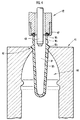
次に、添付の図面を参照しながら本発明の実施の形態についてさらに詳しく説明する。図1は本実施形態のブロー成形装置を示す説明的断面図、図2は図1示のブロー成形装置の要部を拡大して示す説明的断面図、図3は図1示のブロー成形装置の作動を説明するための説明的断面図である。
【0022】
本実施形態のブロー成形装置は、図1示のように、ポリエチレンテレフタレート製のプリフォームWをブロー成形することによって、飲料等を内容物とするPETボトル(図示せず)を得るものである。プリフォームWは有底円筒形状に形成されており、PETボトルの口部となる開口部W1と、PETボトルの胴部となる胴部形成部W2とによって構成され、開口部W1の基部から外周側に突出して設けられたサポートリングW3を備えている。
【0023】
本実施形態のブロー成形装置は、金型1と、ブローノズル2と、ストレッチロッド3とを備えている。金型1は、前記PETボトルの胴部外形に一致する形状の空洞部4と、前記プリフォームWのサポートリングW3が係合されて装着される環状凹部5とを備えている。尚、金型1は図示しない割型構造とされており、前記PETボトルの軸方向に沿って左右に分割されることにより、成形後のPETボトルを脱型することができるようになっている。
【0024】
ブローノズル2は、円筒状に形成され内周側にプリフォームWの開口部W1を収容可能とされた金属製のノズル本体6と、ノズル本体6の先端部に設けられた当接部材7と、当接部材7とノズル本体6との間に介在された弾性部材であるOリング8と、当接部材7をノズル本体6に保持する保持部材9とを備えている。また、ブローノズル2は、ノズル本体6の内周側に開口部W1を収容したときに、当接部材7がサポートリングW3の上面全周に当接されるようになっており、ノズル本体6の内周側には開口部W1がノズル本体6に接触したときに開口部W1を保護する保護部材10が内嵌されている。
【0025】
そして、ノズル本体6の内周側にはストレッチロッド3が挿通され、ストレッチロッド3とノズル本体6の内周面との間には、図示しない高圧気体供給手段により供給される高圧気体が導通される気体通路11が形成されている。ストレッチロッド3は、図示しない伸縮駆動手段によってブロー成形時に伸長され、プリフォームWを軸方向に延伸する。尚、図1においては、ストレッチロッド3の先端がプリフォームWの開口部W1内方に位置しているが、該ストレッチロッド3は未使用時には開口部W1の上端面よりも上方に位置している。
【0026】
当接部材7は、ポリアミド等の合成樹脂によって環状に形成されたものであり、プリフォームWのサポートリングW3の上面全周に当接される当接面12をその先端部に備え、保持部材9の内周面に沿って図中上下方向に摺動自在とされている。また、当接部材7は、図2に示すように、その外周面が当接面12からノズル本体6の先端部に向けて次第に拡径するテーパー状となっており、当接面12と保持部材9の先端部との間で、該外周面から外方に突出する係合部材13を備えている。
【0027】
次に、図1乃至図3を参照して、本実施形態のブロー成形装置の作動を説明する。
【0028】
本実施形態のブロー成形装置によりブロー成形を行うときには、まず、図1示のように、前工程で延伸可能な温度に加熱されたプリフォームWが、金型1に装着される。プリフォームWは、サポートリングW3を金型1の環状凹部5に係合させることにより金型1に支持されており、開口部W1が金型1上部から露出し、胴部形成部W2が空洞部4内に収納されている。
【0029】
次に、ブローノズル2が、金型1に支持されたプリフォームWの開口部W1をノズル本体6の内周側に収容する一方、当接部材7をサポートリングW3の上面全周に当接させることにより、開口部W1に接続される。そして、ブローノズル2からプリフォームWの内部に高圧気体を導入しつつ、ブローノズル2の内周側に進退自在に備えられたストレッチロッド3を伸長する。この結果、プリフォームWの胴部形成部W2がブロー成形され、空洞部4の形状に一致する胴部外形を備えるPETボトルが得られる。
【0030】
このとき、プリフォームWの開口部W1はノズル本体6の内周側に収容されているので、図2示の開口部W1の内周側14のみならず、外周側15にも前記高圧気体が供給される。この結果、開口部W1の内周側14と、外周側15とで、圧力がほぼ等しくなるので、加熱により開口部W1の機械的強度が低減していたとしても、前記高圧気体の圧力により開口部W1が膨張して外径寸法が規格値を超える等の変形を防止することができる。
【0031】
本実施形態のブロー成形装置は、大量の予備成形体Wを高速で連続して金型1に供給して前記ブロー成形を行うときに、金型1に予備成形体Wが供給されなかった場合にも、ブローノズル2が通常通り作動する。この場合には、環状凹部5にサポートリングW3が装着されていないので、図3に示すように、当接部材7が環状凹部5内に進入し、ブローノズル2の先端部(本実施形態では保持部材9の先端部)が加熱された金型1に接触して損傷することが懸念される。
【0032】
しかし、本実施形態のブロー成形装置では、当接部材7が当接面12からノズル本体6の先端部に向けて次第に拡径するテーパー状の外周面を備え、当接面12と保持部材9の先端部との間で、該外周面から外方に突出する係合部材13を備えている。そこで、当接部材7が環状凹部5内に進入すると、係合部材13が環状凹部5の外周縁に係合し、ブローノズル2の先端部がそれ以上金型1に近接することを防止することができる。従って、ブローノズル2の先端部が加熱された金型1に接触することによる損傷を防止することができる。
【0033】
尚、係合部材13は、環状凹部5の外周縁に係合してブローノズル2の先端部と金型1との近接を妨げることができるものであれば、当接部材7の外周面の全周に亘って設けられていてもよく、該外周面に沿って間欠的に設けられていてもよい。
【0034】
本実施形態では、予備成形体としてプリフォームWを用いてPETボトルのブロー成形を行う場合について説明しているが、プリフォームWに替えて、プリフォームWに一次ブロー成形を施した後に加熱により自由収縮させた、二次ブロー成形を施す前の成形体を用いることもできる。
【図面の簡単な説明】
【図1】本発明に係るブロー成形装置の一構成例を示す説明的断面図。
【図2】図1示のブロー成形装置の要部を拡大して示す説明的断面図。
【図3】図1示のブロー成形装置の作動を説明するための説明的断面図。
【図4】従来のブロー成形装置の構成例を示す説明的断面図。
【符号の説明】
1…金型、 2…ブローノズル、 4…空洞部、 5…環状凹部、 7…当接部材、 8…弾性部材、 12…当接面、 13…係合部材、 W…予備成形体、 W1…開口部、 W3…サポートリング。[0001]
BACKGROUND OF THE INVENTION
The present invention relates to a blow molding apparatus used for blow molding of a synthetic resin bottle such as polyethylene terephthalate.
[0002]
[Prior art]
2. Description of the Related Art Conventionally, as a molding apparatus for polyethylene terephthalate resin bottles (hereinafter abbreviated as PET bottles), one having a configuration shown in FIG. 4 is known. This type of apparatus includes a
[0003]
The
[0004]
When blow molding is performed using the
[0005]
Next, the
[0006]
Then, a
[0007]
In addition, the PET bottle is subjected to primary blow molding to the preform W so as to exceed the target bottle shape, and then subjected to secondary blow molding by the
[0008]
In the PET bottle, since the body portion is stretched by the blow molding, excellent heat resistance and mechanical strength can be obtained, but the opening W 1 above the support ring W 3 is not stretched at all. Therefore, heat resistance and mechanical strength due to stretching cannot be obtained. Therefore, the preform W, by whitened in advance the opening W 1 heating crystallization have been made to impart the heat resistance and mechanical strength.
[0009]
However, when subjected to the blow-molded to the preform W of body portion forming portion W 2 is heated to a stretchable temperature, may opening W 1 is heated above the softening temperature, the In spite of being given mechanical strength by heat crystallization, there is a disadvantage that it cannot withstand the pressure of the high-pressure air introduced from the
[0010]
[Problems to be solved by the invention]
An object of the present invention is to provide a blow molding apparatus that eliminates such inconvenience and that does not deform the opening of the preform when the preform of the synthetic resin bottle is blow molded.
[0011]
[Means for Solving the Problems]
In order to achieve such an object, the present invention includes a hollow portion having a shape matching the outer shape of the body portion of a synthetic resin bottle, and a heated synthetic resin preform is attached to the hollow portion and blow-molded. In the blow molding apparatus for a synthetic resin bottle, comprising: a mold; and a blow nozzle for introducing a high pressure gas for blow molding into the preform from the opening of the preform mounted on the mold. a blow nozzle openings of the inner peripheral side can accommodate cylindrical, the tip of the blow nozzle, the is supported lifting respect preform in contact with the direction, the base portion of the opening of the preform An annular contact member that has an abutment surface that comes into airtight contact with the entire upper surface of the support ring that protrudes from the outer peripheral side when the contact member comes into contact with the support ring; Close to the tip of the blow nozzle Characterized in that the abutment member is Tamahatsu deformed while maintaining the airtightness maintaining state and an elastic annular member is pressed against the said support ring is provided.
[0012]
According to the blow molding apparatus of the present invention, the blow nozzle has a cylindrical shape capable of accommodating the opening of the preformed body on the inner peripheral side. Therefore, when the preform is mounted in the cavity, the blow nozzle accommodates the opening of the preform on the inner peripheral side and connects to the opening.
[0013]
In this case, the the distal end portion of the blow nozzle are gills Bei abutment member the blow nozzle by abutment member, support ring which protrudes from the outer peripheral side from the base of the opening of the preform Airtightly contacts the entire upper surface of the plate. The abutting member is pressed against the support ring by the elastic member, and at the same time, is kept in close contact with the tip of the blow nozzle, thus maintaining airtightness.
[0014]
Therefore, when the blow nozzle is connected to the opening of the preform by the contact member as described above, when the high pressure gas for blow molding is introduced from the blow nozzle into the preform, the opening The high-pressure gas is introduced into both the inner peripheral side and the outer peripheral side. Therefore, according to the blow molding apparatus of the present invention, the pressures on the inner peripheral side and the outer peripheral side of the opening of the preform that has been heated to a stretchable temperature are substantially equal, and the opening is formed of the high-pressure gas. It is possible to prevent deformation due to pressure.
[0015]
In the blow molding apparatus of the present invention, the mold includes an annular recess to which the support ring of the preform is engaged and attached, and usually the upper surface of the support ring engaged with the annular recess. The abutting member is abutted against. At this time, since the contact member is interposed between the tip of the blow nozzle and the support ring, the tip of the blow nozzle has a gap between the die and the die. It is prevented from colliding with.
[0016]
By the way, when the blow molding is performed by continuously supplying a large number of preforms to the mold at a high speed, the preform may not be supplied to the mold. Operates normally. As described above, when the blow nozzle operates normally even though the preform is not supplied to the mold, the contact member enters the annular recess, while the tip of the blow nozzle is There is a risk of contact with the mold on the outer peripheral side of the annular recess.
[0017]
When the tip of the blow nozzle repeatedly contacts the die, the die itself is heated, so that the tip of the blow nozzle is inevitably damaged.
[0018]
Therefore, in the blow molding apparatus according to the present invention, the mold includes an annular recess to which the support ring of the preform is engaged and attached, and the contact member extends from the contact surface to the tip of the blow nozzle. A taper-shaped outer peripheral surface that gradually expands in the direction of the part, protrudes outward from the outer peripheral surface between the contact surface and the tip of the blow nozzle, and engages with the outer peripheral edge of the annular recess. An engagement member for preventing contact between the tip of the blow nozzle and the mold is provided.
[0019]
According to the above configuration, when the blow nozzle operates normally and the contact member enters the annular recess even though the preform is not supplied to the mold, the corresponding contact is obtained. The engaging member provided on the outer peripheral surface of the member engages with the outer peripheral edge of the annular recess. As a result, the tip of the blow nozzle can be prevented from coming closer to the mold, and contact with the mold can be prevented.
[0020]
The preform subjected to blow molding in the blow molding apparatus of the present invention may be a preform itself, and is subjected to secondary blow molding in which the preform is subjected to primary blow molding and then freely contracted by heating. It may be a previous molded body.
[0021]
DETAILED DESCRIPTION OF THE INVENTION
Next, embodiments of the present invention will be described in more detail with reference to the accompanying drawings. FIG. 1 is an explanatory sectional view showing a blow molding apparatus of the present embodiment, FIG. 2 is an explanatory sectional view showing an enlarged main part of the blow molding apparatus shown in FIG. 1, and FIG. 3 is a blow molding apparatus shown in FIG. It is explanatory sectional drawing for demonstrating the action | operation of.
[0022]
As shown in FIG. 1, the blow molding apparatus of the present embodiment blows a polyethylene terephthalate preform W to obtain a PET bottle (not shown) containing beverages or the like as contents. Preform W is formed into a bottomed cylindrical shape, the opening W 1 as the mouth portion of the PET bottle, constituted by a body portion forming portion W 2 which is a body portion of the PET bottle, the opening W 1 and a support ring W 3 which protrudes to the outer peripheral side from the base.
[0023]
The blow molding apparatus of this embodiment includes a mold 1, a blow nozzle 2, and a
[0024]
The blow nozzle 2 includes a
[0025]
The
[0026]
The
[0027]
Next, with reference to FIG. 1 thru | or FIG. 3, operation | movement of the blow molding apparatus of this embodiment is demonstrated.
[0028]
When blow molding is performed by the blow molding apparatus of the present embodiment, first, a preform W heated to a temperature at which stretching is possible in the previous step is mounted on the mold 1 as shown in FIG. The preform W is supported by the mold 1 by engaging the support ring W 3 with the
[0029]
Then, the blow nozzle 2, the opening W 1 of the support preform W in the mold 1 while accommodating the inner peripheral side of the
[0030]
At this time, since the opening W 1 of the preform W is accommodated on the inner peripheral side of the
[0031]
The blow molding apparatus of the present embodiment is a case where the preform 1 is not supplied to the mold 1 when the blow molding is performed by continuously supplying a large amount of the preform W to the mold 1 at a high speed. In addition, the blow nozzle 2 operates normally. In this case, since the support ring W 3 in the
[0032]
However, in the blow molding apparatus of this embodiment, the
[0033]
Note that the engaging
[0034]
In the present embodiment, the case where the preform W is blow-molded using the preform W as a preform is described. However, instead of the preform W, the preform W is subjected to primary blow molding and then heated. It is also possible to use a molded body that has been freely shrunk and has not been subjected to secondary blow molding.
[Brief description of the drawings]
FIG. 1 is an explanatory cross-sectional view showing an example of the configuration of a blow molding apparatus according to the present invention.
FIG. 2 is an explanatory cross-sectional view showing an enlarged main part of the blow molding apparatus shown in FIG. 1;
3 is an explanatory cross-sectional view for explaining the operation of the blow molding apparatus shown in FIG. 1. FIG.
FIG. 4 is an explanatory cross-sectional view showing a configuration example of a conventional blow molding apparatus.
[Explanation of symbols]
DESCRIPTION OF SYMBOLS 1 ... Mold, 2 ... Blow nozzle, 4 ... Cavity part, 5 ... Annular recessed part, 7 ... Contact member, 8 ... Elastic member, 12 ... Contact surface, 13 ... Engagement member, W ... Pre-molded body, W 1 ... opening, W 3 ... support ring.
Claims (3)
前記予備成形体の開口部を内周側に収容可能な円筒状のブローノズルと、
該ブローノズルの先端部に、前記予備成形体に対して当接する方向に支持され、該予備成形体の開口部の基部から外周側に突出して設けられたサポートリングの上面全周に気密に当接する当接面を有する環状の当接部材と、
該当接部材が該サポートリングに当接したときに、該当接部材と該ブローノズル先端部との密着状態を維持して気密性を保持しつつ弾発的に変形して該当接部材を該サポートリングに圧接させる環状の弾性部材とが設けられていることを特徴とする合成樹脂製ボトルのブロー成形装置。A mold having a hollow portion having a shape corresponding to the outer shape of the body portion of the synthetic resin bottle, a die for mounting the heated synthetic resin preform in the hollow portion and blow-molding, and the mold mounted on the die In a blow molding apparatus for a synthetic resin bottle comprising a blow nozzle for introducing a high pressure gas for blow molding into the preform from the opening of the preform,
A cylindrical blow nozzle capable of accommodating the opening of the preform on the inner peripheral side;
The tip of the blow nozzle, the supporting is lifting in the abutting direction against the preform, hermetically all around the upper surface of the support ring which protrudes from the outer peripheral side from the base of the opening of the preform An annular contact member having a contact surface to contact;
When the abutting member comes into contact with the support ring, the corresponding contact member is elastically deformed while maintaining the tight contact state between the corresponding contact member and the tip of the blow nozzle, and the corresponding contact member is supported by the support ring. An apparatus for blow molding a synthetic resin bottle, comprising: an annular elastic member that is pressed against the ring.
前記当接部材は、前記当接面から前記ブローノズル先端部方向に向けて次第に拡径するテーパー状の外周面を備え、該当接面と該ブローノズル先端部との間で該外周面から外方に突出し、該環状凹部の外周縁に係合して該ブローノズル先端部と該金型との接触を妨げる係合部材を備えることを特徴とする請求項1記載の合成樹脂製ボトルのブロー成形装置。The mold includes an annular recess to which the support ring of the preform is engaged and attached;
The contact member has a tapered outer peripheral surface that gradually increases in diameter from the contact surface toward the blow nozzle tip, and is outside the outer periphery between the contact surface and the blow nozzle tip. The synthetic resin bottle blow according to claim 1, further comprising an engaging member that protrudes in the direction and engages with an outer peripheral edge of the annular recess to prevent contact between the tip of the blow nozzle and the mold. Molding equipment.
Priority Applications (1)
| Application Number | Priority Date | Filing Date | Title |
|---|---|---|---|
| JP2002196623A JP4041359B2 (en) | 2002-07-05 | 2002-07-05 | Blow molding equipment for synthetic resin bottles |
Applications Claiming Priority (1)
| Application Number | Priority Date | Filing Date | Title |
|---|---|---|---|
| JP2002196623A JP4041359B2 (en) | 2002-07-05 | 2002-07-05 | Blow molding equipment for synthetic resin bottles |
Publications (2)
| Publication Number | Publication Date |
|---|---|
| JP2004034567A JP2004034567A (en) | 2004-02-05 |
| JP4041359B2 true JP4041359B2 (en) | 2008-01-30 |
Family
ID=31704602
Family Applications (1)
| Application Number | Title | Priority Date | Filing Date |
|---|---|---|---|
| JP2002196623A Expired - Lifetime JP4041359B2 (en) | 2002-07-05 | 2002-07-05 | Blow molding equipment for synthetic resin bottles |
Country Status (1)
| Country | Link |
|---|---|
| JP (1) | JP4041359B2 (en) |
Families Citing this family (7)
| Publication number | Priority date | Publication date | Assignee | Title |
|---|---|---|---|---|
| KR100628703B1 (en) | 2004-12-06 | 2006-09-29 | (주)피스코엔지니어링 | Supporting device for a preform of Polyethylene terephthalate bottle |
| KR100613658B1 (en) * | 2005-04-28 | 2006-08-22 | (주)피스코엔지니어링 | Supporting device for a polyethylene terephthalate bottle |
| JP4805040B2 (en) * | 2006-07-04 | 2011-11-02 | 石塚硝子株式会社 | Nozzle for PET bottle blow molding |
| DE102007013096A1 (en) * | 2007-03-14 | 2008-09-18 | Krones Ag | Device for treating containers |
| KR101681292B1 (en) | 2012-08-09 | 2016-12-01 | 닛세이 에이. 에스. 비 기카이 가부시키가이샤 | Blow nozzle and blow molding machine |
| JP6430193B2 (en) | 2014-09-25 | 2018-11-28 | 日精エー・エス・ビー機械株式会社 | Blow molding device, blow molding method and preform seal / positioning part |
| EP4067048B1 (en) * | 2021-03-31 | 2023-11-22 | TI Automotive Technology Center GmbH | Method for producing an assembly for the transport of media and assembly |
-
2002
- 2002-07-05 JP JP2002196623A patent/JP4041359B2/en not_active Expired - Lifetime
Also Published As
| Publication number | Publication date |
|---|---|
| JP2004034567A (en) | 2004-02-05 |
Similar Documents
| Publication | Publication Date | Title |
|---|---|---|
| JP5206372B2 (en) | Manufacturing method of resin container and blow molding apparatus | |
| CA2635878C (en) | Method and device for processing preforms | |
| JP3787165B2 (en) | Blow molding nozzles for plastic containers and equipment with such nozzles | |
| US11161293B2 (en) | Blow nozzle with holes for directional blowing | |
| JP5829566B2 (en) | Blow molding equipment | |
| US10029403B2 (en) | Method and device for producing preforms with special geometries | |
| JPH06143392A (en) | Method of molding heat resistant container | |
| KR900700347A (en) | Blown plastic container | |
| JP6788389B2 (en) | Blow Molded Preforms for Multiple Bottles and Multiple Bottles | |
| JP4041359B2 (en) | Blow molding equipment for synthetic resin bottles | |
| JP5691521B2 (en) | Method for producing a synthetic resin container | |
| US6852267B1 (en) | Method for producing tubular containers | |
| CA2166202C (en) | Biaxial orientation blow molding method and preform holding jig | |
| KR101975644B1 (en) | Manufacturing method and manufacturing apparatus for hollow container | |
| JP2006517484A (en) | Stretched container screw and manufacturing method | |
| US4317793A (en) | Process for the production of oriented hollow bodies | |
| JP3513673B2 (en) | Manufacturing method and apparatus for plastic bottles and mandrel for holding cap | |
| JPH0339226A (en) | Method for stretching parison in stretching blow molding | |
| US11305475B1 (en) | Stretch rod for inflating a preform | |
| JPH0733056B2 (en) | Method and apparatus for producing hollow molded article from thermoplastic synthetic resin | |
| JP4251026B2 (en) | Method for producing a synthetic resin container | |
| JP6367641B2 (en) | Composite container and manufacturing method thereof | |
| JPH05228986A (en) | Biaxial stretching blow molded bottle and manufacture thereof | |
| CN116901404A (en) | Stretching rod for container forming | |
| JP2010000669A (en) | Preform for stretch blow molding |
Legal Events
| Date | Code | Title | Description |
|---|---|---|---|
| A621 | Written request for application examination |
Free format text: JAPANESE INTERMEDIATE CODE: A621 Effective date: 20050608 |
|
| A711 | Notification of change in applicant |
Free format text: JAPANESE INTERMEDIATE CODE: A712 Effective date: 20051209 |
|
| A977 | Report on retrieval |
Free format text: JAPANESE INTERMEDIATE CODE: A971007 Effective date: 20070621 |
|
| A131 | Notification of reasons for refusal |
Free format text: JAPANESE INTERMEDIATE CODE: A131 Effective date: 20070814 |
|
| A521 | Request for written amendment filed |
Free format text: JAPANESE INTERMEDIATE CODE: A523 Effective date: 20070907 |
|
| TRDD | Decision of grant or rejection written | ||
| A01 | Written decision to grant a patent or to grant a registration (utility model) |
Free format text: JAPANESE INTERMEDIATE CODE: A01 Effective date: 20071030 |
|
| A61 | First payment of annual fees (during grant procedure) |
Free format text: JAPANESE INTERMEDIATE CODE: A61 Effective date: 20071109 |
|
| FPAY | Renewal fee payment (event date is renewal date of database) |
Free format text: PAYMENT UNTIL: 20101116 Year of fee payment: 3 |
|
| R150 | Certificate of patent or registration of utility model |
Free format text: JAPANESE INTERMEDIATE CODE: R150 Ref document number: 4041359 Country of ref document: JP Free format text: JAPANESE INTERMEDIATE CODE: R150 |
|
| FPAY | Renewal fee payment (event date is renewal date of database) |
Free format text: PAYMENT UNTIL: 20101116 Year of fee payment: 3 |
|
| FPAY | Renewal fee payment (event date is renewal date of database) |
Free format text: PAYMENT UNTIL: 20111116 Year of fee payment: 4 |
|
| R250 | Receipt of annual fees |
Free format text: JAPANESE INTERMEDIATE CODE: R250 |
|
| FPAY | Renewal fee payment (event date is renewal date of database) |
Free format text: PAYMENT UNTIL: 20121116 Year of fee payment: 5 |
|
| R250 | Receipt of annual fees |
Free format text: JAPANESE INTERMEDIATE CODE: R250 |
|
| FPAY | Renewal fee payment (event date is renewal date of database) |
Free format text: PAYMENT UNTIL: 20121116 Year of fee payment: 5 |
|
| FPAY | Renewal fee payment (event date is renewal date of database) |
Free format text: PAYMENT UNTIL: 20131116 Year of fee payment: 6 |
|
| R250 | Receipt of annual fees |
Free format text: JAPANESE INTERMEDIATE CODE: R250 |
|
| R250 | Receipt of annual fees |
Free format text: JAPANESE INTERMEDIATE CODE: R250 |
|
| R250 | Receipt of annual fees |
Free format text: JAPANESE INTERMEDIATE CODE: R250 |
|
| R250 | Receipt of annual fees |
Free format text: JAPANESE INTERMEDIATE CODE: R250 |
|
| R250 | Receipt of annual fees |
Free format text: JAPANESE INTERMEDIATE CODE: R250 |
|
| R250 | Receipt of annual fees |
Free format text: JAPANESE INTERMEDIATE CODE: R250 |
|
| R250 | Receipt of annual fees |
Free format text: JAPANESE INTERMEDIATE CODE: R250 |
|
| R250 | Receipt of annual fees |
Free format text: JAPANESE INTERMEDIATE CODE: R250 |
|
| R250 | Receipt of annual fees |
Free format text: JAPANESE INTERMEDIATE CODE: R250 |
|
| R250 | Receipt of annual fees |
Free format text: JAPANESE INTERMEDIATE CODE: R250 |
|
| EXPY | Cancellation because of completion of term |