JP3787165B2 - Blow molding nozzles for plastic containers and equipment with such nozzles - Google Patents
Blow molding nozzles for plastic containers and equipment with such nozzles Download PDFInfo
- Publication number
- JP3787165B2 JP3787165B2 JP50386499A JP50386499A JP3787165B2 JP 3787165 B2 JP3787165 B2 JP 3787165B2 JP 50386499 A JP50386499 A JP 50386499A JP 50386499 A JP50386499 A JP 50386499A JP 3787165 B2 JP3787165 B2 JP 3787165B2
- Authority
- JP
- Japan
- Prior art keywords
- blow molding
- nozzle
- blow
- mold
- blank
- Prior art date
- Legal status (The legal status is an assumption and is not a legal conclusion. Google has not performed a legal analysis and makes no representation as to the accuracy of the status listed.)
- Expired - Fee Related
Links
Images


Classifications
-
- B—PERFORMING OPERATIONS; TRANSPORTING
- B29—WORKING OF PLASTICS; WORKING OF SUBSTANCES IN A PLASTIC STATE IN GENERAL
- B29C—SHAPING OR JOINING OF PLASTICS; SHAPING OF MATERIAL IN A PLASTIC STATE, NOT OTHERWISE PROVIDED FOR; AFTER-TREATMENT OF THE SHAPED PRODUCTS, e.g. REPAIRING
- B29C49/00—Blow-moulding, i.e. blowing a preform or parison to a desired shape within a mould; Apparatus therefor
- B29C49/42—Component parts, details or accessories; Auxiliary operations
- B29C49/58—Blowing means
-
- B—PERFORMING OPERATIONS; TRANSPORTING
- B29—WORKING OF PLASTICS; WORKING OF SUBSTANCES IN A PLASTIC STATE IN GENERAL
- B29C—SHAPING OR JOINING OF PLASTICS; SHAPING OF MATERIAL IN A PLASTIC STATE, NOT OTHERWISE PROVIDED FOR; AFTER-TREATMENT OF THE SHAPED PRODUCTS, e.g. REPAIRING
- B29C49/00—Blow-moulding, i.e. blowing a preform or parison to a desired shape within a mould; Apparatus therefor
- B29C49/42—Component parts, details or accessories; Auxiliary operations
- B29C2049/4294—Sealing means
-
- B—PERFORMING OPERATIONS; TRANSPORTING
- B29—WORKING OF PLASTICS; WORKING OF SUBSTANCES IN A PLASTIC STATE IN GENERAL
- B29C—SHAPING OR JOINING OF PLASTICS; SHAPING OF MATERIAL IN A PLASTIC STATE, NOT OTHERWISE PROVIDED FOR; AFTER-TREATMENT OF THE SHAPED PRODUCTS, e.g. REPAIRING
- B29C49/00—Blow-moulding, i.e. blowing a preform or parison to a desired shape within a mould; Apparatus therefor
- B29C49/42—Component parts, details or accessories; Auxiliary operations
- B29C49/58—Blowing means
- B29C2049/5806—Means for fixing the blowing means with the mould
- B29C2049/5813—Hydraulic
-
- B—PERFORMING OPERATIONS; TRANSPORTING
- B29—WORKING OF PLASTICS; WORKING OF SUBSTANCES IN A PLASTIC STATE IN GENERAL
- B29C—SHAPING OR JOINING OF PLASTICS; SHAPING OF MATERIAL IN A PLASTIC STATE, NOT OTHERWISE PROVIDED FOR; AFTER-TREATMENT OF THE SHAPED PRODUCTS, e.g. REPAIRING
- B29C49/00—Blow-moulding, i.e. blowing a preform or parison to a desired shape within a mould; Apparatus therefor
- B29C49/42—Component parts, details or accessories; Auxiliary operations
- B29C49/58—Blowing means
- B29C2049/5827—Blowing means not touching the preform
-
- B—PERFORMING OPERATIONS; TRANSPORTING
- B29—WORKING OF PLASTICS; WORKING OF SUBSTANCES IN A PLASTIC STATE IN GENERAL
- B29C—SHAPING OR JOINING OF PLASTICS; SHAPING OF MATERIAL IN A PLASTIC STATE, NOT OTHERWISE PROVIDED FOR; AFTER-TREATMENT OF THE SHAPED PRODUCTS, e.g. REPAIRING
- B29C2949/00—Indexing scheme relating to blow-moulding
- B29C2949/07—Preforms or parisons characterised by their configuration
- B29C2949/0715—Preforms or parisons characterised by their configuration the preform having one end closed
-
- B—PERFORMING OPERATIONS; TRANSPORTING
- B29—WORKING OF PLASTICS; WORKING OF SUBSTANCES IN A PLASTIC STATE IN GENERAL
- B29C—SHAPING OR JOINING OF PLASTICS; SHAPING OF MATERIAL IN A PLASTIC STATE, NOT OTHERWISE PROVIDED FOR; AFTER-TREATMENT OF THE SHAPED PRODUCTS, e.g. REPAIRING
- B29C49/00—Blow-moulding, i.e. blowing a preform or parison to a desired shape within a mould; Apparatus therefor
- B29C49/02—Combined blow-moulding and manufacture of the preform or the parison
- B29C49/06—Injection blow-moulding
-
- B—PERFORMING OPERATIONS; TRANSPORTING
- B29—WORKING OF PLASTICS; WORKING OF SUBSTANCES IN A PLASTIC STATE IN GENERAL
- B29C—SHAPING OR JOINING OF PLASTICS; SHAPING OF MATERIAL IN A PLASTIC STATE, NOT OTHERWISE PROVIDED FOR; AFTER-TREATMENT OF THE SHAPED PRODUCTS, e.g. REPAIRING
- B29C49/00—Blow-moulding, i.e. blowing a preform or parison to a desired shape within a mould; Apparatus therefor
- B29C49/08—Biaxial stretching during blow-moulding
- B29C49/10—Biaxial stretching during blow-moulding using mechanical means for prestretching
- B29C49/12—Stretching rods
-
- B—PERFORMING OPERATIONS; TRANSPORTING
- B29—WORKING OF PLASTICS; WORKING OF SUBSTANCES IN A PLASTIC STATE IN GENERAL
- B29C—SHAPING OR JOINING OF PLASTICS; SHAPING OF MATERIAL IN A PLASTIC STATE, NOT OTHERWISE PROVIDED FOR; AFTER-TREATMENT OF THE SHAPED PRODUCTS, e.g. REPAIRING
- B29C49/00—Blow-moulding, i.e. blowing a preform or parison to a desired shape within a mould; Apparatus therefor
- B29C49/28—Blow-moulding apparatus
- B29C49/30—Blow-moulding apparatus having movable moulds or mould parts
- B29C49/36—Blow-moulding apparatus having movable moulds or mould parts rotatable about one axis
-
- B—PERFORMING OPERATIONS; TRANSPORTING
- B29—WORKING OF PLASTICS; WORKING OF SUBSTANCES IN A PLASTIC STATE IN GENERAL
- B29C—SHAPING OR JOINING OF PLASTICS; SHAPING OF MATERIAL IN A PLASTIC STATE, NOT OTHERWISE PROVIDED FOR; AFTER-TREATMENT OF THE SHAPED PRODUCTS, e.g. REPAIRING
- B29C49/00—Blow-moulding, i.e. blowing a preform or parison to a desired shape within a mould; Apparatus therefor
- B29C49/42—Component parts, details or accessories; Auxiliary operations
- B29C49/4236—Drive means
-
- B—PERFORMING OPERATIONS; TRANSPORTING
- B29—WORKING OF PLASTICS; WORKING OF SUBSTANCES IN A PLASTIC STATE IN GENERAL
- B29C—SHAPING OR JOINING OF PLASTICS; SHAPING OF MATERIAL IN A PLASTIC STATE, NOT OTHERWISE PROVIDED FOR; AFTER-TREATMENT OF THE SHAPED PRODUCTS, e.g. REPAIRING
- B29C49/00—Blow-moulding, i.e. blowing a preform or parison to a desired shape within a mould; Apparatus therefor
- B29C49/42—Component parts, details or accessories; Auxiliary operations
- B29C49/56—Opening, closing or clamping means
Abstract
Description
【0001】
【発明の属する技術分野】
本発明は、プラスチック材料の予備加工段階の際に得られるプレフォームまたは中間容器等のブランクをブロー成形して、小瓶やボトルなどのプラスチック製容器を製造する機械に実施する改良に関する。本発明は特に、これらの機械に装備する、ブロー成形ノズルと称される部品に関する。
【0002】
【従来の技術】
プラスチック製のブランクをブロー成形することによりプラスチック製容器を製造することは、今では公知である。
【0003】
ブランクがプレフォームである場合、プレフォームは、射出(注入)成形型にプラスチック材料を射出するか、または成形型にプラスチック材料をブロー押出成形することにより得られる。プレフォームは次に、製造する容器の特徴に応じて多少とも複雑化した適切な熱処理を受けるか、または製造する容器のくぼみを備えた仕上型に配置されるか、あるいはその両方である。その場合、ブロー成形ノズルは、プレフォームの開口部(首部)に挿入され、ブロー成形流体、一般には高圧空気をプレフォーム内に射出してプレフォームを膨らませ、成形型の壁に沿って材料を張り付けることにより容器を得ることができる。好適には、特に予め射出されたプレフォームから容器を構成する本出願人の機械では、伸長ロッドを用いたプレフォームの延伸(または伸長)を予め行ってからブロー成形をするか、あるいは、こうした延伸がブロー成形と一緒に行われる。また好適には、高圧空気によるブロー成形の前に延伸を行う場合、延伸は、それよりも低い圧力の空気によるプレブロー成形と合わせて行われ、特に延伸時に材料がロッド上できつく締められないようにする。
【0004】
ブランクが中間容器である場合、中間容器は一般に第1の容器から得られ、第1の容器自体が、第1の成形型におけるプレフォームのブロー成形により得られる。第1の容器は、第1の成形型から出した後で、一般には熱による特定の処理を受けて中間容器が得られる。この中間容器を第2の成形型に配し、中間容器は、この第2の成形型内で、前述のノズルと同じノズルを用いたブロー成形流体の射出により最終容器に加工される。
【0005】
本出願人による欧州特許第237459号および第442836号は、設備の2つの実施形態を記載しており、射出プレフォームにより第1の容器を得てから、第1の容器を中間容器に加工した後で、特に加熱充填時あるいは炭酸飲料を用いる時に適切な機械特性を備えた、最終容器を得ることができる。
【0006】
一般に、このタイプの方法および装備は、単一の中間容器を得る段階を必要とする。最終容器を得る前に、複数個の中間容器を連続して得るように検討することもむろん可能である。
【0007】
最終容器の製造に使用される成形型、または中間容器となる一定容器が得られる各成形型は、一般に、互いに分離または接近可能な少なくとも2個の部分からなる。各部分は、獲得する容器(底、壁、ショルダ)の半型を含む。
【0008】
しかしながら既知の成形型は好適には、3つの部分すなわち、容器の底のくぼみを備えた部分と、容器の壁およびショルダを構成するための2つの部分とを含む。このような好適な構造により、容器の底が一定のタイプの凹凸を有する場合(特に花弁状の底)、成形型から外しやすくなる。
【0009】
ブランクを設置する場合や容器を排出する場合、これらの部分は互いに分離している(離れている)。ブロー成形段階では(延伸およびまたはプレブロー成形の有無を問わず)、これらの部分は接近しており、成形型が閉じている。
【0010】
(中間または最終)容器製造機械または機器の欠点は、使用されるブロー成形ノズルの構造に起因する。
【0011】
最終容器の首部が、一般にプレフォームの製造時に得られることは既知である。
【0012】
プレフォームが、最終容器に直接、あるいは中間容器に加工されるとき、首部の寸法は、変更してはならないか、または変更したとしてもごくわずかである。同様に、またその結果として、中間容器の首部の寸法も変更してはならないか、あるいは変更したとしてもごくわずかであり、そのため最終容器はいずれの場合にも、首部がプレフォームの首部と同じにならなくてはならない。実際、首部は、ねじ付きの栓を受容するためのねじ山か、はめ込みキャップまたは栓を受容するための補強端を含む。従って、プレフォーム成形後に首部の変形を制御することは難しく、首部は、順次加工した後でそのままの状態に保持することが好ましい。
【0013】
そのために、プレフォームを最終または中間容器に加工する段階、また、この場合は中間容器を別の容器(さらなる中間容器または最終容器)に加工する段階で、首部は成形型の外部で支持され、ブロー成形により変形されない。
【0014】
ノズルは、ブランクの開口部に挿入できるようにブロー成形端(ノズルの先端)をきつく締め付ける管から構成される。一般に、ノズルの端の断面は円錐台形である。円錐台、従ってノズルの底辺の直径は、前記開口部の直径よりも小さい。そのためノズルを首部に挿入すると、接触により、円錐台とブランクの口縁の内周との間でブロー成形時の気密性を確保するとともに、成形型に対して適正な位置にブランクを強く保持することができる。
【0015】
【発明が解決しようとする課題】
しかし、このタイプのノズルは、次のような理由から完全に適合されているというわけではない。
− ブロー成形時に強い圧力が必要であるために(一般に本出願人の機械では40バール)、ノズルとブランクとの間に大きな支持圧を及ぼして漏れがないようにしなければならない。従って首部は、支持の際にノズルによって変形されないように十分な剛性を与えるべく、材料の厚さを十分に厚くしなければならない。ところで、容器の原価は大部分が材料費に関連する。しばらく前から、原価を下げるために軽量の首部をもつブランクを製造する傾向があるが、しかし下限が存在し、それを越えるとノズルが首部の破裂を引き起こす。
− 異なる容器の様々なシリーズを製造するために同一設備を使用できる。ユーザは時には、その設備を個別的な要求に合わせて変えることがある。首部の高さを変える場合およびまたは首部の直径を変える場合、ノズルの行程の調整を変えたり、またはノズル自体を変えたり、あるいはその両方を変えなければならない。従って時間のロスが発生し、さらには設備に追加費用がかかる。
− これらのノズルは、滅菌または殺菌流体を用いる滅菌または殺菌容器のブロー成形には適さない。何故なら、口縁の内部とノズルとの間の接触ゾーンは、ブロー成形前に滅菌または殺菌されていない場合には、そのままの状態にとどまるからである。従って汚染された、または殺菌されていない粒子がそこにあって内部を汚染するおそれがある。
− 一般的に伸長ロッドがある場合、伸長ロッドは、ノズル内に設けられてノズルの長手方向の軸に沿って配向される円筒形の穴の内部を軸方向に摺動し、ロッドの周囲に環状の空間が空けられ、ブロー成形流体がロッドの周囲でこの穴を通る。しかし、この空間の断面は必然的に有限なので流体の通過は制動される。
【0016】
本発明は、これらの欠点を解消することを目的とする。
【0017】
【課題を解決するための手段】
本発明によれば、ブロー成形ノズルは、ブロー成形型内の首部の下で支持されるブランク内部にブロー成形流体を供給し、前記首部の一部が成形型の壁から出るようにし、ブランクに流体を供給する穴を含み、ブランクが成形型に設置されてノズルがブロー成形位置にあるとき、穴の寸法が、前記一部を覆うように、またノズルの先端を構成するブランクに向かい合ったその周辺縁が成形型で支持されるように構成され、気密手段が、この支持位置に設けられることを特徴とする。
【0018】
従って、本発明によるノズルは、上記の問題を全て解決することができる。つまり、
・ 気密性を確保するにあたりプレフォームで直接支持されないので、軽量首部を使用できる。
・ 個別的な要素に関係する問題が解決される。すなわち機械が処理するよう求められている最大首部を収容できるように穴を補正する。
・ ブロー成形流体は首部の周囲に達するので、殺菌または滅菌に関する問題が解決される。ブロー成形流体がこのように首部の周囲に達するので、容器の内部ばかりではなく首部の外部もまた洗浄される。
・ ノズルの先端が首部の内部ではなく外部にあるので、伸長ロッドがある場合でも、ブロー成形流体に対して通過断面をより大きくすることができ、ブロー成形の能率が上がる。
【0019】
第1の実施形態では、気密手段が、ノズルの先端の端に固定される。
【0020】
第2の実施形態では、気密手段が、ノズルを結合する設備の成形型に固定される。
【0021】
本発明の他の特徴および長所は、添付図面に関してなされた以下の説明を通読すれば明らかになるだろう。
【0022】
【発明の実施の形態】
図1および図2は、本発明によるノズルの第1の実施形態と、ノズルを結合可能なブロー成形装置の部分とを示している。
【0023】
ノズル1は、ほぼ円筒形のスリーブ形本体2を有し、同軸の孔でその全長にわたって穿孔されている。この貫通孔は、ノズルの軸5に同軸の2個の穴(オリフィス)3、4から構成され、その第1端により互いに接続されている。
【0024】
本発明によれば、これらの穴の内の第1の穴3は、後述するように、ブロー成形設備にノズルを設置するとき、ブランクに流体を供給する穴を構成する。
【0025】
図1と図2に示した実施形態では、リップ形パッキン6が第1の穴3の第2端の周囲に固定されており、軸方向に出ていて、実際にはノズルの先端7を構成している。このパッキン6の機能は、後述するように、ブロー成形時に気密性を確保することにある。パッキン6は、ノズル本体2に設けられた第1の穴3の第2端の周囲に、たとえば前記第2端の周囲に留められる保持リング8を用いて保持される。
【0026】
好適には、通気孔9、10が、保持リング8の厚みを径方向に貫通する。通気孔の機能については後述する。これらの通気孔は好適には、保持リング8の周囲に一定の間隔で配分され、また保持リングの内側で、ノズル本体2と、パッキン6のノズルとは反対側の端であって実際にはノズルの先端7を構成する端との間の支持面11に通じる。
【0027】
周知のように、ノズル1は、第1の穴3が設けられている側と反対の側でノズルジャッキ12に固定される。より詳しくは、本体2が、ピストン14に結合する軸13に結合され、ピストン14がシリンダ15内を摺動し、ピストン、シリンダ、軸の全体がジャッキを構成する。
【0028】
好適には、図1と図2に示したように、ノズルの本体2が軸13の端にねじ留めされる。このために、本体2に設けられた第2の穴4がねじ立てされ、軸13の端が、対応するようにねじ切りされている。
【0029】
ジャッキには2つの効果がある。つまり、このためにシリンダ15の一端に設けられた第1の穴16が、ピストン、従ってノズル1を成形型17の方に駆動でき、第2の穴18が、成形型からノズルを離すことができる。
【0030】
周知のように、ピストン14と、ピストンを延長した軸13からなる全体には、ノズル1およびジャッキ12の対称軸5に同軸の筒状穴19が、その全長に沿って開けられている。
【0031】
ブランク21に結合される伸長ロッド20が、この穴に配置される。穴19の内径はロッド20の外径よりも大きいので、環状スペース22がロッド20の周囲に設けられ、ノズル1の第1の穴3に向けて、従ってブランク21に向けて、プレブロー成形またはブロー成形、あるいはその両方の流体の通過を可能にし、それによって成形型17で所望の容器を製造する。
【0032】
環状スペース22は、プレブロー成形またはブロー成形、あるいはその両方のために、加圧流体の供給管23と接続されている。供給管23は、周知のように、1つまたは複数の流体供給源に接続されている。
【0033】
ロッド20は、シリンダ15と、ピストン14、軸13、ノズル1の組立部品とからなる機械に関して摺動可能である。ロッドの既知の移動手段、すなわち別のジャッキまたはカムローラ機構、あるいはその両方、もしくは他のあらゆる適切な手段については図示しない。
【0034】
また周知のように、ロッド20のガイド軸受24、25は、シリンダ15の端と、軸13およびノズル1の間の接合部とにそれぞれ設けられている。さらに、少なくともシリンダ端のガイドは気密である。このために、軸受24が気密であるか、または好適には、この軸受をパッキン26によって補完する。
【0035】
この位置での気密性は、ロッド20の周囲のブロー成形流体のあらゆる漏れを回避することを目的とする。
【0036】
軸13およびノズル1の間の接合部にあるガイド軸受25は、たとえばリングからなり、軸13の端に設けられた対応するくり抜き27にはめ込まれ、軸13に組み立てられたときにノズルによって所定の位置に保持される。リングはさらに、少なくとも2個の穴28、29によりその高さ全体で穿孔され、2個の穴はそれぞれ、環状スペース22とノズル1の第1の穴3とに接続され、ブロー成形流体が、供給管23からノズルの先端に循環できるようにする。
【0037】
もちろん軸13へのノズルの固定は、軸13にノズル1を十分に締め付けるか、またはパッキンや他のあらゆる既知の機械(気密テープ、接合ペースト、繊維束など)を用いて気密に行われる。
【0038】
図1では、ノズル1および伸長ロッド20が、上昇位置で示されている(成形型がノズルの下に配置されている場合)。従ってノズルはブランク21から離れ、ロッド20は、ノズル内に引っ込んでいる。
【0039】
ブランク21は、ここではプレフォームであり、獲得する容器のくぼみ30を収容する成形型17内に配置される。
【0040】
図2では、ノズルがブロー成形位置にある。ノズルの先端7、より詳しくは、この先端を構成するパッキン6が、成形型の上縁31で支持され、ロッド20は、その自由端がプレフォームの底で支持される位置、すなわちプレフォームの延伸を行う直前の位置に示されている。
【0041】
この図は、ブランク21の首部32がこの穴内にゆったりと入り、すなわち穴で覆われるようにノズル1の第1の穴3の寸法を構成することを示している。
【0042】
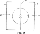
好適には、また周知のように、パッキン6が支持される成形型17の上縁31の部分はリングであり、2個の半型36、37の間の接合部の面35の位置で互いに向かい合った2個の半リング33、34からなる。このリングは交換可能な部品である。
【0043】
ノズルの先端7の近傍にある通気孔9、10の機能は、加圧流体がまだ残っているのに成形後にノズルが成形型から離れる(上昇する)とき、パッキン6が劣化しなようにすることにある。これらの通気孔がない場合、パッキン6のリップ形部は、ノズル内を支配する圧力が強いため、ノズルが上昇し始めると外部に出される傾向がある。
【0044】
通気孔がある場合には、ノズルが成形型17から離れ始めると、パッキンはもはや首部リング33、34に対して強くは押しつけられない。
【0045】
実際にパッキンの内周面は、内部圧があるためにノズルの本体2内の支持ゾーンから離れる傾向があるので、パッキンとノズル本体との間に隙間ができ、この隙間から通気孔、従って外部に向かって流体の一部を排出することができる。
【0046】
図4と図5は、ノズルの実施形態を示す。図6は、この実施形態と協働する成形型の構成を示す。
【0047】
この実施形態に示されたノズルと図1および図2に示されたノズルとの相違点は、ノズルの先端7と成形型との間の気密性を確保するための手段だけである。従って、同じ要素は同じ参照数字を有し、それらに関与する部分については図1および図2の説明を参照されたい。
【0048】
ノズル1は、2個の穴3、4を開けた本体2を含む。
【0049】
これらの穴の第1の穴3は、ブランク39の首部38を覆う役割をする。ブランク39は、ここでは、本出願人名義の欧州特許第442836号に記載されたような、縮んだ本体をもつ中間容器である。
【0050】
ねじ立てした第2の穴4は、ピストン14に結合される軸13の対応するねじ切りにねじ留めされ、伸長ロッド20はジャッキで移動する。
【0051】
このノズルと、図1および図2に記載したノズルとの相違点は、ノズルの先端7がパッキンからは構成されずに、第1の穴3の開口部から外側に向いた縁40から構成され、この場合、第1の穴3は、全体が本体2のブロック内に設けられている。
【0052】
気密性は、ノズルが所定の位置にあるときパッキン41により確保される(図5)。パッキン41は、半円弧形パッキンの2個の部分42、43からなる。この2個の部分は、各半型46、47の上壁44、45にそれぞれ配置されているか、または好適には首部リングがある場合(図6)、各半型にそれぞれ配置された、2個の半リング48、49からなる首部リングに配置される。
【0053】
この実施形態の長所は、パッキンを所定の位置に固定しやすく、ノズルが上昇するときに外れないことにある。
【0054】
驚くべきことに、本発明によるノズルは、ブロー成形時に首部リングの位置でブランク21、39を成形型にしっかりと押しつけなくても済むことが認められた。従って、設置したときに成形型にブランクを保持する伸長ロッド20を使用せずに容器を製造することが全く可能である。伸長ロッドを使用しなくても、流体の作用下でブランクが振動せず、流体が、ブランク外部から成形型内部に排出されるというようなことはない。流体は、特定の問題を起こさずにブランク内部に向けられる。
【0055】
本発明はもちろん、記載した実施形態に限定されるものではない。特に、ジャッキへのノズルの固定は、ねじ立てされた穴4とジャッキの軸13上の対応するねじ切りとを介するのとは別のあらゆる方法で実施可能である。同様に、伸長ロッド20は、ノズルではなく設備自体の付属品にすぎないので、なくてもよい。
【図面の簡単な説明】
【図1】ノズルがブロー成形位置にないときに、ノズルの第1の実施形態を使用する設備の一部を示す概略断面図である。
【図2】ノズルがブロー成形位置にあるときの、第1の実施形態に対応する断面図である。
【図3】この第1の実施形態で使用可能な成形型の、閉鎖位置における簡略化した上面図である。
【図4】ノズルがブロー成形位置にないときに、ノズルの第2の実施形態を使用する設備の一部を示す概略断面図である。
【図5】ノズルがブロー成形位置にあるときの、第2の実施形態に対応する断面図である。
【図6】第2の実施形態とともに使用可能な成形型の、閉鎖位置における簡略化した上面図である。[0001]
BACKGROUND OF THE INVENTION
The present invention relates to an improvement carried out on a machine for producing a plastic container such as a small bottle or a bottle by blow-molding a blank such as a preform or an intermediate container obtained in the preliminary processing stage of a plastic material. In particular, the present invention relates to a part, called a blow molding nozzle, equipped on these machines.
[0002]
[Prior art]
It is now known to produce plastic containers by blow molding plastic blanks.
[0003]
If the blank is a preform, the preform is obtained by injecting a plastic material into an injection (injection) mold or by blow-extruding the plastic material into a mold. The preform is then subjected to a suitable heat treatment that is more or less complicated depending on the characteristics of the container to be manufactured and / or placed in a finishing mold with a recess in the container to be manufactured. In that case, the blow molding nozzle is inserted into the opening (neck) of the preform, and a blow molding fluid, generally high-pressure air, is injected into the preform to inflate the preform, and the material is blown along the mold wall. A container can be obtained by pasting. Preferably, in the Applicant's machine, where the container is constructed from a pre-injected preform, the preform may be stretched (or stretched) using a stretch rod before blow molding or such Stretching is performed together with blow molding. Also preferably, when stretching is performed prior to blow molding with high-pressure air, stretching is performed in combination with pre-blow molding with air at a lower pressure so that the material is not tightly clamped on the rod during stretching. To.
[0004]
When the blank is an intermediate container, the intermediate container is generally obtained from the first container, and the first container itself is obtained by blow molding the preform in the first mold. After the first container is removed from the first mold, it is generally subjected to a specific treatment by heat to obtain an intermediate container. This intermediate container is placed in a second mold, and the intermediate container is processed into a final container by injection of blow molding fluid using the same nozzle as the above-described nozzle in the second mold.
[0005]
European Patent Nos. 237,459 and 4,428,36 by the applicant describe two embodiments of the facility, where a first container is obtained by an injection preform and then the first container is processed into an intermediate container. Later, a final container with suitable mechanical properties can be obtained, especially when heated and filled or when using a carbonated beverage.
[0006]
In general, this type of method and equipment requires obtaining a single intermediate container. It is of course possible to consider obtaining a plurality of intermediate containers in succession before obtaining the final container.
[0007]
Each mold used to produce the final container, or each mold that provides a fixed container that is an intermediate container, generally consists of at least two parts that are separable or accessible from each other. Each part includes a mold half of the container (bottom, wall, shoulder) to be acquired.
[0008]
However, the known mold preferably comprises three parts: a part with a recess in the bottom of the container and two parts for constituting the container wall and shoulder. Such a suitable structure facilitates removal from the mold when the bottom of the container has a certain type of irregularities (particularly a petal-like bottom).
[0009]
When installing a blank or discharging a container, these parts are separated (separated) from each other. In the blow molding stage (with or without stretching and / or pre-blow molding), these parts are close and the mold is closed.
[0010]
The disadvantages of (intermediate or final) container manufacturing machines or equipment are due to the structure of the blow molding nozzle used.
[0011]
It is known that the neck of the final container is generally obtained during the manufacture of the preform.
[0012]
When the preform is processed directly into the final container or into an intermediate container, the neck dimensions should or should not be changed. Similarly, and as a result, the size of the neck of the intermediate container must not be changed or only slightly changed, so that the final container in each case is the same as the neck of the preform. It must be. In fact, the neck includes a thread for receiving a threaded plug or a stiffening end for receiving an inset cap or plug. Therefore, it is difficult to control the deformation of the neck after preform molding, and it is preferable to keep the neck as it is after being sequentially processed.
[0013]
To that end, the neck is supported on the outside of the mold in the stage of processing the preform into a final or intermediate container, in this case the intermediate container into another container (further intermediate container or final container), Not deformed by blow molding.
[0014]
The nozzle consists of a tube that tightly clamps the blow molded end (nozzle tip) so that it can be inserted into the opening of the blank. In general, the cross section of the end of the nozzle is frustoconical. The diameter of the truncated cone and hence the bottom of the nozzle is smaller than the diameter of the opening. Therefore, when the nozzle is inserted into the neck, the contact ensures the airtightness during blow molding between the frustoconical and the inner periphery of the blank mouth, and strongly holds the blank at an appropriate position with respect to the mold. be able to.
[0015]
[Problems to be solved by the invention]
However, this type of nozzle is not perfectly adapted for the following reasons.
-Due to the high pressure required during blow molding (generally 40 bar for the Applicant's machine), a large support pressure must be applied between the nozzle and the blank to prevent leakage. Therefore, the neck must have a sufficiently thick material to provide sufficient rigidity so that it is not deformed by the nozzle during support. By the way, the cost of the container is mostly related to the material cost. For some time, there has been a tendency to produce blank necks with a light neck to reduce costs, but there is a lower limit beyond which the nozzle can cause the neck to burst.
-The same equipment can be used to manufacture different series of different containers. Users sometimes change their equipment to meet individual requirements. When changing the height of the neck and / or changing the diameter of the neck, the adjustment of the nozzle stroke must be changed, or the nozzle itself must be changed, or both. This results in time loss and additional equipment costs.
-These nozzles are not suitable for sterilization or sterilization container blow molding using a sterilization or sterilization fluid. This is because the contact zone between the inside of the lip and the nozzle remains intact if it has not been sterilized or sterilized prior to blow molding. Thus, contaminated or unsterilized particles may be present and contaminate the interior.
-If there is an elongated rod in general, the elongated rod is axially slid within a cylindrical hole provided in the nozzle and oriented along the longitudinal axis of the nozzle, around the rod An annular space is opened and blow molding fluid passes through this hole around the rod. However, since the cross section of this space is necessarily finite, the passage of fluid is damped.
[0016]
The present invention aims to eliminate these drawbacks.
[0017]
[Means for Solving the Problems]
According to the present invention, the blow molding nozzle supplies blow molding fluid therein blank is supported under the neck of the blow mold, a portion of the neck portion so that it extends out from the wall of the mold, the blank When the blank is installed in the mold and the nozzle is in the blow molding position, the dimensions of the hole cover that part and face the blank that forms the tip of the nozzle. The peripheral edge is configured to be supported by a mold, and an airtight means is provided at the support position.
[0018]
Therefore, the nozzle according to the present invention can solve all the above problems. That means
-Lightweight neck can be used because it is not directly supported by the preform to ensure airtightness.
・ Problems related to individual elements are solved. That is, the hole is corrected to accommodate the largest neck that the machine is required to process.
• The blow molding fluid reaches around the neck, thus solving sterilization or sterilization problems. As the blow molding fluid thus reaches around the neck, not only the interior of the container but also the exterior of the neck is cleaned.
-Since the tip of the nozzle is not the inside of the neck but the outside, even if there is an elongated rod, the passage cross section can be made larger with respect to the blow molding fluid, and the efficiency of blow molding is increased.
[0019]
In the first embodiment, the airtight means is fixed to the end of the tip of the nozzle.
[0020]
In 2nd Embodiment, an airtight means is fixed to the shaping | molding die of the installation which couple | bonds a nozzle.
[0021]
Other features and advantages of the present invention will become apparent upon reading the following description made with reference to the accompanying drawings.
[0022]
DETAILED DESCRIPTION OF THE INVENTION
1 and 2 show a first embodiment of a nozzle according to the invention and a part of a blow molding device to which the nozzle can be combined.
[0023]
The
[0024]
According to the present invention, of these holes, the
[0025]
In the embodiment shown in FIGS. 1 and 2, the lip-shaped
[0026]
Preferably, the
[0027]
As is well known, the
[0028]
Preferably, the
[0029]
The jack has two effects. That is, the
[0030]
As is well known, a
[0031]
An
[0032]
The
[0033]
The
[0034]
As is well known, the
[0035]
The airtightness at this position aims to avoid any leakage of blow molding fluid around the
[0036]
The guide bearing 25 at the joint between the
[0037]
Of course, the fixing of the nozzle to the
[0038]
In FIG. 1, the
[0039]
The blank 21 is here a preform and is placed in the
[0040]
In FIG. 2, the nozzle is in the blow molding position. The tip 7 of the nozzle, more specifically, the packing 6 constituting this tip is supported by the
[0041]
This figure shows that the dimension of the
[0042]
Preferably, as is also well known, the part of the
[0043]
The function of the
[0044]
If there is a vent, the packing is no longer strongly pressed against the neck rings 33, 34 when the nozzle begins to move away from the
[0045]
Actually, the inner peripheral surface of the packing tends to move away from the support zone in the
[0046]
4 and 5 show an embodiment of the nozzle. FIG. 6 shows the configuration of the mold that cooperates with this embodiment.
[0047]
The only difference between the nozzle shown in this embodiment and the nozzle shown in FIGS. 1 and 2 is the means for ensuring airtightness between the tip 7 of the nozzle and the mold. Therefore, the same elements have the same reference numerals, and the description of FIGS. 1 and 2 is referred to for the parts involved.
[0048]
The
[0049]
The
[0050]
Second holes 4 that vertical screw is screwed into the corresponding threading of the
[0051]
The difference between this nozzle and the nozzle described in FIGS. 1 and 2 is that the tip 7 of the nozzle is not composed of packing but is composed of an
[0052]
Airtightness is ensured by the packing 41 when the nozzle is in a predetermined position (FIG. 5). The packing 41 is composed of two
[0053]
The advantage of this embodiment is that it is easy to fix the packing in place and does not come off when the nozzle is raised.
[0054]
Surprisingly, it has been found that the nozzle according to the invention does not require the
[0055]
The invention is of course not limited to the embodiments described. In particular, the fixing of the nozzle to the jack can be carried out in any way other than via a tapped hole 4 and a corresponding threading on the
[Brief description of the drawings]
FIG. 1 is a schematic cross-sectional view showing a portion of equipment using a first embodiment of a nozzle when the nozzle is not in a blow molding position.
FIG. 2 is a cross-sectional view corresponding to the first embodiment when the nozzle is in a blow molding position.
FIG. 3 is a simplified top view of a mold that can be used in this first embodiment in a closed position;
FIG. 4 is a schematic cross-sectional view showing a portion of the equipment that uses the second embodiment of the nozzle when the nozzle is not in the blow molding position.
FIG. 5 is a cross-sectional view corresponding to the second embodiment when the nozzle is in a blow molding position.
FIG. 6 is a simplified top view of a mold that can be used with the second embodiment in a closed position.
Claims (13)
前記ブロー成形ノズル(1)が、ブランクに流体を供給する穴(3)を含んでおり、
前記穴(3)は、ブランクがブロー成形型に設置されてブロー成形ノズル(1)がブロー成形位置にあるとき、前記一部をゆったりと覆うと共に、ブロー成形ノズルの先端(7)を構成する前記穴の周辺縁が、気密手段(6;42、43)を介してブロー成形型の前記壁(31;44、45)で支持されるような、形状を有していることを特徴とする、前記ブロー成形設備。Respect; (46, 47, 37), a portion of the neck (32, 38) is the blow mold wall blow mold; blank supported by the neck as exits (31 44, 45) ( 21; 39) a blow molding facility provided with a blow molding nozzle (1) for supplying a blow molding fluid.
The blow molding nozzle (1) includes a hole (3) for supplying fluid to the blank;
It said hole (3), when the blank is placed in the blow mold blow molding nozzle (1) is in the blow molding position, said with some leisurely cover, constituting the tip of the blow-molding nozzle (7) peripheral edge of said hole, airtight means; blow mold of the wall through the (6, 43); as supported by (31 44, 45), characterized in that it has the shape The blow molding equipment .
Applications Claiming Priority (3)
| Application Number | Priority Date | Filing Date | Title |
|---|---|---|---|
| FR97/07609 | 1997-06-16 | ||
| FR9707609A FR2764544B1 (en) | 1997-06-16 | 1997-06-16 | NOZZLE FOR BLOWING PLASTIC CONTAINERS AND INSTALLATION PROVIDED WITH SUCH A NOZZLE |
| PCT/FR1998/001208 WO1998057794A1 (en) | 1997-06-16 | 1998-06-11 | Nozzle for blow moulding plastic containers and installation provided with same |
Related Child Applications (1)
| Application Number | Title | Priority Date | Filing Date |
|---|---|---|---|
| JP2002106626A Division JP2002307541A (en) | 1997-06-16 | 2002-04-09 | Blow molding nozzle for plastic container and apparatus having the nozzle |
Publications (2)
| Publication Number | Publication Date |
|---|---|
| JP2000512944A JP2000512944A (en) | 2000-10-03 |
| JP3787165B2 true JP3787165B2 (en) | 2006-06-21 |
Family
ID=9508155
Family Applications (2)
| Application Number | Title | Priority Date | Filing Date |
|---|---|---|---|
| JP50386499A Expired - Fee Related JP3787165B2 (en) | 1997-06-16 | 1998-06-11 | Blow molding nozzles for plastic containers and equipment with such nozzles |
| JP2002106626A Pending JP2002307541A (en) | 1997-06-16 | 2002-04-09 | Blow molding nozzle for plastic container and apparatus having the nozzle |
Family Applications After (1)
| Application Number | Title | Priority Date | Filing Date |
|---|---|---|---|
| JP2002106626A Pending JP2002307541A (en) | 1997-06-16 | 2002-04-09 | Blow molding nozzle for plastic container and apparatus having the nozzle |
Country Status (16)
| Country | Link |
|---|---|
| US (1) | US6464486B1 (en) |
| EP (1) | EP0989931B1 (en) |
| JP (2) | JP3787165B2 (en) |
| KR (1) | KR100381035B1 (en) |
| CN (1) | CN1080183C (en) |
| AT (1) | ATE199003T1 (en) |
| AU (1) | AU743369B2 (en) |
| BR (1) | BR9810130A (en) |
| CA (1) | CA2293843C (en) |
| DE (1) | DE69800516T2 (en) |
| DK (1) | DK0989931T3 (en) |
| ES (1) | ES2154497T3 (en) |
| FR (1) | FR2764544B1 (en) |
| GR (1) | GR3035475T3 (en) |
| PT (1) | PT989931E (en) |
| WO (1) | WO1998057794A1 (en) |
Families Citing this family (74)
| Publication number | Priority date | Publication date | Assignee | Title |
|---|---|---|---|---|
| FR2790704B1 (en) * | 1999-03-09 | 2001-07-20 | Sidel Sa | BLOWING MACHINE COMPRISING IMPROVED MEANS FOR CONTROLLING THE MOVEMENTS OF A BLOWER NOZZLE |
| FR2804059B1 (en) * | 2000-01-20 | 2002-08-30 | Sidel Sa | CONTAINER BLOWING MACHINE COMPRISING MEANS FOR ORIENTATION OF PREFORMS IN THE BLOW MOLD |
| FR2814392B1 (en) * | 2000-09-25 | 2002-12-20 | Sidel Sa | STRETCH-BLOWING MACHINE HAVING IMPROVED DRAWING ROD CONTROL |
| DE10063553B4 (en) * | 2000-12-20 | 2005-02-24 | Krones Ag | Device for blow molding containers, in particular plastic bottles |
| FR2833512B1 (en) * | 2001-12-13 | 2004-02-27 | Sidel Sa | INSTALLATION FOR BLowing TERMOPLASTIC POLYMER CONTAINERS |
| EP1556646B1 (en) * | 2002-10-07 | 2013-12-18 | Becton, Dickinson and Company | Method for filling a container having at least one flexible component |
| FR2848905B1 (en) * | 2002-12-19 | 2006-07-28 | Sidel Sa | TUYERE-CLOCHE BLOW MOLDING SYSTEM |
| FR2871721B1 (en) * | 2004-06-16 | 2006-09-29 | Sidel Sas | BLOW PIPE BLOW MOLDING OR FLUID INSTALLATION FOR MANUFACTURING THERMOPLASTIC AND MOLDED CONTAINERS FOR SUCH A PLANT |
| FR2872082B1 (en) * | 2004-06-23 | 2006-10-06 | Sidel Sas | INSTALLATION FOR BLOWING CONTAINERS IN THERMOPLASTIC MATERIAL |
| FR2874193A1 (en) * | 2004-08-12 | 2006-02-17 | Sidel Sas | Blower or stretch blower for thermoplastic bottles from preforms has thrust surfaces of half-moulds made with positioners to interact with projection on preform neck |
| US7421957B2 (en) * | 2004-09-25 | 2008-09-09 | Michael Baez | Overhead storage system |
| FR2876942B1 (en) * | 2004-10-22 | 2008-08-15 | Sidel Sas | BLOWING INSTALLATION FOR THE MANUFACTURE OF THERMOPLASTIC CONTAINERS |
| FR2889673B1 (en) * | 2005-08-12 | 2007-10-26 | Sidel Sas | BLOWING INSTALLATION COMPRISING A PIPE EQUIPPED WITH A LIP SEAL |
| FR2889672B1 (en) | 2005-08-12 | 2009-08-07 | Sidel Sas | FUNCTIONAL ASSEMBLY FOR INSTALLATION FOR BLOWING CONTAINERS AND INSTALLATION COMPRISING SUCH AN ASSEMBLY |
| US8367172B2 (en) * | 2005-11-03 | 2013-02-05 | Flexform Technologies, Llc | Blow-molded composite compositions and methods |
| US8857637B2 (en) | 2006-03-06 | 2014-10-14 | Plastipak Packaging, Inc. | Lightweight plastic container and preform |
| US10457437B2 (en) | 2006-03-06 | 2019-10-29 | Plastipak Packaging, Inc. | Lightweight plastic container and preform |
| DE102006039962B4 (en) * | 2006-08-25 | 2016-02-18 | Khs Corpoplast Gmbh | Method and apparatus for blow molding containers |
| FR2909028B1 (en) * | 2006-11-28 | 2009-02-13 | Sidel Participations | INSTALLATION FOR BLOWING HOLLOW BODIES. |
| CN101626987B (en) * | 2007-01-30 | 2012-09-05 | 康宁股份有限公司 | Ultra thin glass drawing and blowing |
| DE102007013096A1 (en) | 2007-03-14 | 2008-09-18 | Krones Ag | Device for treating containers |
| FR2914876B1 (en) * | 2007-04-10 | 2009-07-10 | Sidel Participations | DEVICE FOR MOLDING, BY BLOWING OR STRETCH BLOWING, CONTAINERS OF THERMOPLASTIC MATERIAL |
| FR2914875B1 (en) * | 2007-04-13 | 2009-07-10 | Sidel Participations | MOLDING DEVICE FOR THE MANUFACTURE OF THERMOPLASTIC CONTAINERS BY BLOWING OR STRETCH BLOWING. |
| FR2915923B1 (en) | 2007-05-10 | 2009-07-10 | Inergy Automotive Systems Res | PROCESS FOR MANUFACTURING A FUEL TANK WITH INTERNAL ACCESSORY |
| FR2918916B1 (en) * | 2007-07-19 | 2009-10-23 | Sidel Participations | INSTALLATION FOR THE MANUFACTURE OF CONTAINERS FROM A PREFORM AND METHOD FOR CONTROLLING THE BLOWING MEANS OF SUCH A INSTALLATION |
| FR2920692B1 (en) | 2007-09-10 | 2010-02-26 | Sidel Participations | METHOD FOR FORMING CONTAINERS COMPRISING A SCAN STAGE OF THE INTERNAL VOLUME OF THE RECIPIENT HAVING A VARIABLE DURATION OVER AT LEAST ONE TIME OF COMPENSATION GIVEN |
| FR2921582B1 (en) | 2007-09-27 | 2013-11-22 | Sidel Participations | INSTALLATION FOR BLOWING CONTAINERS IN THERMOPLASTIC MATERIAL |
| US7972554B2 (en) * | 2007-10-24 | 2011-07-05 | Nestle Waters Management & Technology | Air cartridge devices and methods of using same |
| FR2924974B1 (en) | 2007-12-17 | 2012-12-28 | Sidel Participations | MOLD FOR MANUFACTURING THERMOPLASTIC CONTAINERS AND BLOW-MOLDING OR BLOW-STRETCHING EQUIPMENT EQUIPPED WITH SUCH A MOLD |
| JP5103247B2 (en) * | 2008-03-31 | 2012-12-19 | 株式会社青木固研究所 | Molding device for stretch blow of container having mouth at upper corner |
| DE102008025881A1 (en) | 2008-05-29 | 2009-12-03 | Krones Ag | Container i.e. vessel, and/or blowing nozzle, expanding device for blowing container, has sealing device with support section that extends in longitudinal direction of container and pressed against container mouth in radial direction |
| DE102008025775A1 (en) | 2008-05-29 | 2009-12-10 | Krones Ag | Expanding device i.e. blast nozzle, for expanding container during manufacture, has sealing device sealing space between container and wall body and pressed against outer circumference of container by longitudinal movement of pressing body |
| DE102008025880A1 (en) | 2008-05-29 | 2009-12-03 | Krones Ag | Device for expanding containers with a fitting at the mouth of the container seal |
| FR2940171B1 (en) | 2008-12-24 | 2011-01-21 | Sidel Participations | BLOWING INSTALLATION FOR MANUFACTURING A CONTAINER FROM A DRAFT |
| DE102009020738A1 (en) * | 2009-05-11 | 2010-11-25 | Krones Ag | Apparatus for blow molding plastic preforms with reduced dead volume |
| DE102009023406A1 (en) * | 2009-05-29 | 2010-12-02 | Krones Ag | Blowing machine with CIP cleaning system for the production of plastic bottles, in particular PET bottles |
| JP5619897B2 (en) | 2009-09-07 | 2014-11-05 | スィデル・パルティスィパスィヨン | Method for changing mold |
| FR2949704B1 (en) | 2009-09-07 | 2011-11-25 | Sidel Participations | METHOD FOR CHANGING THE MOLDING IMPRESSIONS OF A BLOWING STATION FOR PLASTIC CONTAINERS |
| FR2949706A1 (en) | 2009-09-07 | 2011-03-11 | Sidel Participations | MOLDING DEVICE EQUIPPED WITH FIXED CONTROL MEANS WITH TIGHTENING OF A HALF-MOLD BY SLIDING FASTENING PENES |
| FR2949703A1 (en) | 2009-09-07 | 2011-03-11 | Sidel Participations | MOLDING DEVICE EQUIPPED WITH MEANS FOR FIXING A HALF-MOLD BY ATTACTION AGAINST THE BACKGROUND OF A HOUSING ASSOCIATED WITH A MOLD HOLDER |
| FR2949705B1 (en) | 2009-09-07 | 2016-09-16 | Sidel Participations | MOLDING DEVICE EQUIPPED WITH FIXING MEANS BY ATTACHING A HALF-MOLD TO A MOLD HOLDER |
| FR2949709B1 (en) | 2009-09-08 | 2011-10-07 | Sidel Participations | MACHINE FOR MANUFACTURING CONTAINERS COMPRISING A DEVICE CONTROL MODULE OF A MOLDING UNIT FOR OPERATING A MOLD CHANGE |
| WO2011030183A1 (en) * | 2009-09-10 | 2011-03-17 | Gea Procomac S.P.A. | Device for blowing and stretching a plastic parison for obtaining a container |
| US8287270B2 (en) | 2009-09-30 | 2012-10-16 | Printpack Illinois Inc. | Methods and systems for thermoforming with billets |
| FR2954207B1 (en) | 2009-12-21 | 2013-09-27 | Sidel Participations | MACHINE FOR MANUFACTURING CONTAINERS COMPRISING A MOLD CHANGE ASSISTANCE SYSTEM |
| FR2963580B1 (en) | 2010-08-03 | 2012-09-28 | Sidel Participations | FORMING MACHINE EQUIPPED WITH A MOLDING UNIT COMPRISING COMPENSATION MEANS CONTROLLED BY AUTOMATICALLY ACTUATED VALVES |
| WO2012018732A2 (en) * | 2010-08-04 | 2012-02-09 | Silgan Plastics Corporation | Blow molding method and apparatus for forming squeezable plastic container |
| FR2972385B1 (en) | 2011-03-08 | 2013-04-26 | Sidel Participations | AUTOMATED SYSTEM FOR CHANGING THE MOLD OF A MOLDING UNIT EQUIPPED WITH A CONTAINER MANUFACTURING MACHINE |
| FR2972386B1 (en) | 2011-03-08 | 2014-10-10 | Sidel Participations | ASSEMBLY ASSEMBLY SYSTEM FOR MOLDING UNIT MOLDING MACHINE FOR CONTAINER MANUFACTURING MACHINE |
| FR2974750B1 (en) | 2011-05-03 | 2014-04-25 | Sidel Participations | VALVE CONTROL DEVICE FOR A BLOW MOLDING MOLDING INSTALLATION COMPRISING INDIVIDUALLY ACTUABLE VALVES |
| CN103717494B (en) * | 2011-08-08 | 2015-11-25 | 帝斯克玛股份有限公司 | Be filled with the degas method of the container of soda |
| US9555574B2 (en) * | 2011-12-27 | 2017-01-31 | Discma Ag | Blow molding device and a method for manufacturing a blow molded container |
| FR2986735B1 (en) | 2012-02-09 | 2014-02-28 | Sidel Participations | DEVICE FOR BOXING A MOUTH BOTTOM OF A BASE OF A CONTAINER DURING THE SHEET |
| FR2990135B1 (en) | 2012-05-04 | 2016-05-06 | Sidel Participations | ASSEMBLY FOR DECONTAMINATION OF A CONTAINER MANUFACTURING MOLD AND DECONTAMINATION METHOD |
| KR101681292B1 (en) | 2012-08-09 | 2016-12-01 | 닛세이 에이. 에스. 비 기카이 가부시키가이샤 | Blow nozzle and blow molding machine |
| FR3001913B1 (en) | 2013-02-14 | 2015-02-27 | Sidel Participations | "INSTALLATION FOR FORMING BLOWED CONTAINERS COMPRISING AN IMPROVED DEVICE FOR CONTROLLING A BLOWING FLUID DISPENSING VALVE" |
| FR3005891B1 (en) | 2013-05-27 | 2015-05-22 | Sidel Participations | "FORMING INSTALLATION COMPRISING A VALVE CONTROLLED BY A STEERING FLUID AND EQUIPPED WITH MAGNETIC ASSISTANCE" |
| FR3011763B1 (en) | 2013-10-14 | 2015-12-11 | Sidel Participations | "MOLDING UNIT FOR THE MANUFACTURE OF CONTAINERS HAVING A COMPENSATION CLAMP" |
| WO2015104212A1 (en) * | 2014-01-07 | 2015-07-16 | Norgren Ag | Blowing cylinder |
| FR3017324B1 (en) * | 2014-02-13 | 2016-03-04 | Sidel Participations | MOLDING UNIT FOR THE MANUFACTURE OF CONTAINERS FROM PREFORMS OF PLASTIC MATERIAL |
| JP6430193B2 (en) * | 2014-09-25 | 2018-11-28 | 日精エー・エス・ビー機械株式会社 | Blow molding device, blow molding method and preform seal / positioning part |
| JP6330692B2 (en) * | 2015-02-25 | 2018-05-30 | 株式会社村田製作所 | Electronic components |
| FR3035348B1 (en) | 2015-04-23 | 2017-04-14 | Sidel Participations | METHOD FOR COOLING HEATED MOLDS OF A MOLDING MACHINE OF CONTAINERS |
| CN105415647A (en) * | 2015-11-21 | 2016-03-23 | 赵淑丽 | Gas pin assembly of injection molding machine for teaching |
| FR3055573B1 (en) | 2016-09-07 | 2018-08-31 | Sidel Participations | LOCKING DEVICE FOR A MOLDING UNIT OF THERMOPLASTIC CONTAINERS |
| DE102017010272B3 (en) * | 2017-11-07 | 2019-03-21 | Khs Corpoplast Gmbh | Forming and filling station of a plant for producing filled containers from preforms by introduced under pressure into the preform contents |
| FR3078648B1 (en) | 2018-03-07 | 2020-02-14 | Sidel Participations | LOCKING FINGER FOR A THERMOPLASTIC CONTAINER MOLDING UNIT |
| FR3078647B1 (en) | 2018-03-07 | 2020-02-14 | Sidel Participations | LOCKING FINGER FOR A THERMOPLASTIC CONTAINER MOLDING UNIT |
| EP3670144B1 (en) * | 2018-12-21 | 2021-10-20 | "TES" Spolka z Ograniczona Odpowiedzialnoscia | A unit for blow-moulding of bottles intended for hot filling from pet preforms |
| FR3103131B1 (en) | 2019-11-20 | 2021-11-05 | Sidel Participations | "Method of orienting a preform in a mold" |
| FR3104484B1 (en) | 2019-12-17 | 2021-12-03 | Sidel Participations | Angular indexing method of a preform |
| FR3105753B1 (en) | 2019-12-26 | 2022-01-07 | Sidel Participations | "Process for angular orientation of hollow bodies in a container manufacturing facility" |
| MX2022010000A (en) * | 2020-02-14 | 2022-09-19 | Liquiform Group Llc | Container preform and forming/filling nozzle each configured to provide a seal therebetween. |
| CN115071040B (en) * | 2022-06-27 | 2024-02-27 | 江苏理工学院 | Preparation device and preparation method of artificial blood vessel with microstructure on inner surface |
Family Cites Families (18)
| Publication number | Priority date | Publication date | Assignee | Title |
|---|---|---|---|---|
| US1647532A (en) * | 1927-11-01 | Edward h | ||
| US1832080A (en) * | 1928-10-18 | 1931-11-17 | Owens Illinois Glass Co | Machine for blowing hollow glass articles |
| US2331687A (en) * | 1938-05-13 | 1943-10-12 | Hartford Empire Co | Method of and machine for forming hollow articles of plastic materials |
| US3640671A (en) * | 1969-02-26 | 1972-02-08 | Monsanto Co | Apparatus for venting and releasing plastic articles from a blow mold |
| US3819317A (en) * | 1972-10-30 | 1974-06-25 | Haskon Inc | Apparatus for blow molding and injecting cooling gas |
| DE2342134C3 (en) * | 1973-08-21 | 1980-12-11 | Johannes 5205 St. Augustin Mehnert | Device for producing hollow bodies from thermoplastic material |
| US3871856A (en) * | 1973-10-11 | 1975-03-18 | Emhart | Self-aligning baffle and blowhead assembly |
| US3880640A (en) * | 1973-12-05 | 1975-04-29 | Owens Illinois Inc | Blow head with sound energy absorbing means |
| SE7601488L (en) | 1975-03-03 | 1976-09-06 | Emhart Corp | WAY TO SPRAY BLOW FORM BIAXIALLY ORIENTED IHALA PLASTIC CONTAINERS |
| GB2131011B (en) * | 1982-11-30 | 1986-07-09 | Emhart Ind | Blowhead arrangement for a glassware container manufacturing machine |
| US4509969A (en) * | 1983-03-04 | 1985-04-09 | Emhart Industries, Inc. | Blowhead apparatus |
| US4552527A (en) * | 1984-10-09 | 1985-11-12 | Sewell Plastics, Inc. | Nozzle assembly |
| US4818212A (en) * | 1986-06-02 | 1989-04-04 | Cincinnati Milacron Inc. | Blow molding apparatus |
| FR2658119B1 (en) * | 1990-02-13 | 1992-06-05 | Sidel Sa | METHOD AND INSTALLATION FOR MANUFACTURING CONTAINERS, SUCH AS BOTTLES, OF POLYETHYLENETEREPHTHALATE, RESISTANT TO RELATIVELY SEVERED THERMAL CONDITIONS DURING THEIR USE. |
| CH683757A5 (en) * | 1990-05-31 | 1994-05-13 | Dynaplast Sa | Integrated Modular machine for the manufacture and packaging of containers terephthalate bioriented polyethylene and blowing modules and filling the component. |
| JP3336477B2 (en) | 1994-04-28 | 2002-10-21 | 株式会社吉野工業所 | Preform holding jig |
| CH690002A5 (en) * | 1995-10-10 | 2000-03-15 | Tetra Pak Plastics Ltd Tetra P | Machine for the production of plastic container. |
| FR2790704B1 (en) * | 1999-03-09 | 2001-07-20 | Sidel Sa | BLOWING MACHINE COMPRISING IMPROVED MEANS FOR CONTROLLING THE MOVEMENTS OF A BLOWER NOZZLE |
-
1997
- 1997-06-16 FR FR9707609A patent/FR2764544B1/en not_active Expired - Fee Related
-
1998
- 1998-06-11 PT PT98930824T patent/PT989931E/en unknown
- 1998-06-11 JP JP50386499A patent/JP3787165B2/en not_active Expired - Fee Related
- 1998-06-11 WO PCT/FR1998/001208 patent/WO1998057794A1/en active IP Right Grant
- 1998-06-11 AU AU81124/98A patent/AU743369B2/en not_active Ceased
- 1998-06-11 CA CA002293843A patent/CA2293843C/en not_active Expired - Fee Related
- 1998-06-11 ES ES98930824T patent/ES2154497T3/en not_active Expired - Lifetime
- 1998-06-11 EP EP98930824A patent/EP0989931B1/en not_active Expired - Lifetime
- 1998-06-11 DE DE69800516T patent/DE69800516T2/en not_active Expired - Lifetime
- 1998-06-11 DK DK98930824T patent/DK0989931T3/en active
- 1998-06-11 US US09/445,483 patent/US6464486B1/en not_active Expired - Lifetime
- 1998-06-11 CN CN98806287A patent/CN1080183C/en not_active Expired - Fee Related
- 1998-06-11 AT AT98930824T patent/ATE199003T1/en not_active IP Right Cessation
- 1998-06-11 KR KR10-1999-7011819A patent/KR100381035B1/en not_active IP Right Cessation
- 1998-06-11 BR BR9810130-7A patent/BR9810130A/en not_active IP Right Cessation
-
2001
- 2001-02-27 GR GR20010400315T patent/GR3035475T3/en not_active IP Right Cessation
-
2002
- 2002-04-09 JP JP2002106626A patent/JP2002307541A/en active Pending
Also Published As
| Publication number | Publication date |
|---|---|
| DK0989931T3 (en) | 2001-03-19 |
| KR100381035B1 (en) | 2003-04-18 |
| AU743369B2 (en) | 2002-01-24 |
| EP0989931A1 (en) | 2000-04-05 |
| US6464486B1 (en) | 2002-10-15 |
| EP0989931B1 (en) | 2001-01-31 |
| BR9810130A (en) | 2000-08-08 |
| JP2002307541A (en) | 2002-10-23 |
| AU8112498A (en) | 1999-01-04 |
| KR20010013801A (en) | 2001-02-26 |
| CA2293843A1 (en) | 1998-12-23 |
| CN1080183C (en) | 2002-03-06 |
| CN1260746A (en) | 2000-07-19 |
| WO1998057794A1 (en) | 1998-12-23 |
| FR2764544B1 (en) | 1999-09-24 |
| CA2293843C (en) | 2004-01-27 |
| ES2154497T3 (en) | 2001-04-01 |
| GR3035475T3 (en) | 2001-05-31 |
| PT989931E (en) | 2001-06-29 |
| ATE199003T1 (en) | 2001-02-15 |
| FR2764544A1 (en) | 1998-12-18 |
| JP2000512944A (en) | 2000-10-03 |
| DE69800516D1 (en) | 2001-03-08 |
| DE69800516T2 (en) | 2001-08-09 |
Similar Documents
| Publication | Publication Date | Title |
|---|---|---|
| JP3787165B2 (en) | Blow molding nozzles for plastic containers and equipment with such nozzles | |
| KR100669304B1 (en) | Method and device for processing preforms | |
| US10011064B2 (en) | Method for producing a plastic bottle, and preform and blowing mold suited therefor | |
| JP5747413B2 (en) | Biaxial stretch blow molding apparatus and container manufacturing method | |
| WO2014103188A1 (en) | Blow-molding device | |
| US9522748B2 (en) | Apparatus for blowing and filling a container with liquid collecting means | |
| JP5806929B2 (en) | Blow molding device and blow molding container manufacturing method | |
| JP4814323B2 (en) | Blowing plant with nozzle provided with lip seal joint | |
| WO2013145511A1 (en) | Blow molding device | |
| US5792491A (en) | Device for sealing a plastic container preform to a blow moulding nozzle | |
| KR100189402B1 (en) | Method of molding large containers by the process of stretch blow molding | |
| AU775363B2 (en) | Method for producing tubular containers | |
| KR100340300B1 (en) | Synthetic Resin Bottle Molding Method and Preform Supports for Biaxial Stretch Blow Molding | |
| JPH11513331A (en) | Machine for manufacturing containers made of plastic material | |
| EP3159137B1 (en) | Manufacturing method and manufacturing apparatus for hollow container | |
| WO2013099073A1 (en) | Blow-molding device and production method for blow-molded container | |
| US9085099B2 (en) | Stretch blow moulding machine and method | |
| JP4041359B2 (en) | Blow molding equipment for synthetic resin bottles | |
| US20210283822A1 (en) | Fixing a preform in stretch blow molding | |
| WO2020240972A1 (en) | Blow molding device | |
| US11345072B2 (en) | Blow molding device | |
| JPH0339226A (en) | Method for stretching parison in stretching blow molding | |
| CN114633455B (en) | Plastic bottle blow molding production equipment and plastic bottle blow molding method | |
| MXPA99011040A (en) | Nozzle for blow moulding plastic containers and installation provided with same | |
| JPH08156080A (en) | Method and apparatus for manufacture of plastic bottle and mandrel for holding neck |
Legal Events
| Date | Code | Title | Description |
|---|---|---|---|
| A521 | Request for written amendment filed |
Free format text: JAPANESE INTERMEDIATE CODE: A523 Effective date: 20060210 |
|
| A61 | First payment of annual fees (during grant procedure) |
Free format text: JAPANESE INTERMEDIATE CODE: A61 Effective date: 20060324 |
|
| R150 | Certificate of patent or registration of utility model |
Free format text: JAPANESE INTERMEDIATE CODE: R150 |
|
| FPAY | Renewal fee payment (event date is renewal date of database) |
Free format text: PAYMENT UNTIL: 20100331 Year of fee payment: 4 |
|
| FPAY | Renewal fee payment (event date is renewal date of database) |
Free format text: PAYMENT UNTIL: 20110331 Year of fee payment: 5 |
|
| FPAY | Renewal fee payment (event date is renewal date of database) |
Free format text: PAYMENT UNTIL: 20110331 Year of fee payment: 5 |
|
| FPAY | Renewal fee payment (event date is renewal date of database) |
Free format text: PAYMENT UNTIL: 20120331 Year of fee payment: 6 |
|
| FPAY | Renewal fee payment (event date is renewal date of database) |
Free format text: PAYMENT UNTIL: 20130331 Year of fee payment: 7 |
|
| FPAY | Renewal fee payment (event date is renewal date of database) |
Free format text: PAYMENT UNTIL: 20140331 Year of fee payment: 8 |
|
| R250 | Receipt of annual fees |
Free format text: JAPANESE INTERMEDIATE CODE: R250 |
|
| R250 | Receipt of annual fees |
Free format text: JAPANESE INTERMEDIATE CODE: R250 |
|
| R250 | Receipt of annual fees |
Free format text: JAPANESE INTERMEDIATE CODE: R250 |
|
| LAPS | Cancellation because of no payment of annual fees |