JP4040710B2 - Processing method for passenger conveyor body frame - Google Patents
Processing method for passenger conveyor body frame Download PDFInfo
- Publication number
- JP4040710B2 JP4040710B2 JP26488396A JP26488396A JP4040710B2 JP 4040710 B2 JP4040710 B2 JP 4040710B2 JP 26488396 A JP26488396 A JP 26488396A JP 26488396 A JP26488396 A JP 26488396A JP 4040710 B2 JP4040710 B2 JP 4040710B2
- Authority
- JP
- Japan
- Prior art keywords
- plate
- tem
- body frame
- base
- upper beam
- Prior art date
- Legal status (The legal status is an assumption and is not a legal conclusion. Google has not performed a legal analysis and makes no representation as to the accuracy of the status listed.)
- Expired - Fee Related
Links
Images
Landscapes
- Escalators And Moving Walkways (AREA)
- Drilling And Boring (AREA)
Description
【0001】
【発明の属する技術分野】
本発明は、いわゆるエスカレータおよび動く歩道等の乗客コンベアにおける本体枠の加工方法と、乗客コンベアの改修時に新設される部品を取付けるための取付補助枠と、乗客コンベアの改修時に新設される部品の取付方法とに関する。
【0002】
【従来の技術】
乗客コンベアの構造概略を図18に示す。図18に示すように乗客コンベアは建物の下階部から上階部に向けて設置された本体枠2を有している。本体枠2の上梁3には、ボルトまたは溶接によりベース1が取り付けられており、このベース1には図18および図19に示すように欄干4を支持するホネ5が取り付けられている。
【0003】
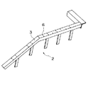
ところで改修等で欄干4を新しい形式のものと交換する場合には、新しい欄干4を支持する為の新しい形式のホネ5およびベース1を新たに上梁3に取り付ける必要がある。図20は、本体枠2から既設の欄干4、ホネ5およびベース1を取り外した状態を示しており、既設のベース1がボルトで取り付けられていた場合、上梁3にはボルト止め用の既設穴6がある。上梁3に新しい形式のベース1を取り付ける場合、溶接かボルト締結のいずれかにより取り付けるが、作業現場が溶接禁止となっている場合は、ベース1をボルトで取り付けなければならない。ベース1をボルトにより取り付けるためには、上梁3にボルト止め用の穴が必要であるが、既設穴6は既設のベース1用に穴開けされているためピッチ、大きさ及び個数等が異なる場合が多く、既設穴6を流用して新しい形式のベース1を取り付けることは通常は不可能である。
【0004】
この為、このような場合には新設されるベース1に対応して上梁3に新たな穴を穿けている。
【0005】
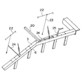
図21および図22は欄干4を変更する際に上梁3にベース1取付用のボルト穴を加工する方法を示したものである。この場合、まず本体枠2に作業基準となるワーキングバー20およびセンターポール21が取り付けられる。ワーキングバー20は本体枠2の長手方向および高さの基準となり、センターポール21は、本体枠2の幅方向の基準となるものである。
【0006】
次に図21および図22に示すようにセンターポール21に張られたピアノ線22に下げ振り23を垂らし、そこから直尺24で幅方向の寸法を測り上梁3にケガキが入れられる。次に幅方向のケガキと長手方向のケガキとが交差する場所にポンチ25が刻印され、電気ドリルにより穴が穿孔される。そしてこの穴を用いて、ボルトによりベース1が取り付けられる。ベース1には、ボルト径よりも大きい径の穴が穿孔され、ベース1の取付作業を行なう場合には、まずボルトを仮締めして取付位置の微調整をすることにより位置決めが行われ、その後ボルトを本締めしてベース1が固定される。その後、ベース1上にホネ5および欄干4が順次取り付けられる。
【0007】
【発明が解決しようとする課題】
しかしながら、ケガキ作業は、図面を見ながら、一箇所ごとに行われるため、作業時間もかかり、作業者がケガキ位置を間違える場合も多くある。また、穿孔作業は、穿孔したい穴の径が大きい場合、ドリルの刃の径の小さいもので下穴を穿孔し、さらにこの下穴より大きい径のドリルで段階的に穿孔を繰り返すことにより所望の穴径を得るようにして行われるため、多くの時間がかかっている。さらにベース1の取付作業も仮締め後の位置の微調整に時間がかかっている。
【0008】
本発明は、このようなことを考慮しなされたものであり、ケガキ作業、穿孔作業、およびベースの取付作業に必要な時間を短縮することができる、乗客コンベアの本体枠の加工方法および新設部品用の取付補助枠、さらに新設部品の取付方法を提供することを目的とする。
【0009】
【課題を解決するための手段】
かかる目的を達成するため、本発明によれば、本体枠上にテムプレートを設置し、このテムプレートに設けられた加工ガイドに従って本体枠を加工する乗客コンベアの本体枠の加工方法であって、前記加工ガイドは、前記本体枠に穿孔される穴径より小さい穴径を有する下穴を有し、前記本体枠を加工する場合、前記下穴にドリルの刃先を当接させ、前記テムプレートごと本体枠を穿孔することを特徴とする乗客コンベアの本体枠の加工方法が提供される。
【0010】
本発明によれば、テムプレートごと本体枠を穿孔することにより、部材取付け用のボルト穴を精度良く容易に形成することができる。
【0011】
好ましくは、前記テムプレートは、本体枠を構成する梁と同一の幅を有している。
【0013】
好ましくは、前記テムプレートは、前記加工ガイドとして、前記テムプレートの端縁に形成された切欠きを更に有しており、前記本体枠を加工する場合、前記切欠きに沿って切欠き加工が行われる。
【0016】
【発明の実施の形態】
以下、図面を参照して本発明の実施の形態について説明する。
第1の実施の形態
まず、第1の実施の形態について説明する。図1乃至図10は本発明の第1の実施の形態を示す図である。
【0017】
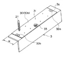
まず、第1の実施の形態において使用されるテムプレート30について説明する。図2に示すように、テムプレート30は上梁3の上面3aと同一の幅Wを有する厚さ略1.6mm程度の鉄板からなる。テムプレート30の厚さは、コスト、重量、および必要とされる強度を考慮して決定されている。また、テムプレート30の全長は、持ち運びの容易さを考慮して2m以下の適当な長さに設定されている。
【0018】
テムプレート30には、改修時に上梁3に新たに取付けられる部材、例えば欄干4を受けるホネ5に形成される取付用のボルト穴の位置に対応する位置に加工ガイドとして下穴31が穿孔されている。この下穴31の直径は、上梁3に開けようとしている取付用のボルト穴より小さくなっている。
【0019】
また、図1に示すように、テムプレート30には、その長手方向の端縁に合いマーク32a,32bが描かれている。また、テムプレート30上に「右・左」、「表・裏」、「上から2番目」等、本体枠2上へのテムプレート30の配置方法を示す文字33が記入されている。
【0020】
次に、このテムプレート30を使用して乗客コンベアを改修する方法について本体枠2の加工方法を中心として図1により説明する。なお、以下の説明において、テムプレート30a〜30dの基本的な構成は上述したテムプレート30と同一であり、下穴31が形成される部位、合いマーク32a,32bの有無および形状、文字33による記載事項等が、テムプレート30a〜30dの取付けられる位置に対応して変更されているのみである。
【0021】
まず、既設の欄干、ホネ、ベースを取外した上梁3の上面3aに対するテムプレート30a〜30dの固定作業が行われる。この固定作業を行うにあたって、上面3aの所定位置に正しく対応するテムプレート30a〜30dが配置されるように、作業者は各テムプレート30a〜30dに記載された文字33を確認することになっている。
【0022】
テムプレート30a〜30dの固定作業を行うにあたって、まず、上梁3の折点3cの近くにテムプレート30aが載置される。この場合、上梁3の上面3aが折点3c近傍において若干のRを持っているため(曲面となっているため)、テムプレート30aの折点3c側の長手方向の端縁は、折点3cからxだけ離間するように設置される。通常、上梁3の上面3aには、折点3cから10mm離れた位置にポンチマークが刻印されているため、このポンチマークにテムプレート30aの長手方向の端縁を一致させることにより、上梁3に対するテムプレート30aの長手方向の位置決めが行われる。さらに、テムプレート30aの幅方向の両端縁を上面3aの幅方向の両端縁と一致させることにより、上梁3に対するテムプレート30aの幅方向の位置決めが行われる。このように位置決めされたテムプレート30aは、図1に示すように、シャコ万力26により上梁3に対して固定される。
【0023】
テムプレート30aの位置決めが終了すると、これに隣接するテムプレート30bの位置決めが行われる。テムプレート30の長手方向に関する位置決めは、テムプレート30aおよびテムプレート30bの長手方向の端縁同士を密接させることにより行われる。なお、この場合、テムプレート30aおよび30bの長手方向の端縁に描かれた合いマーク32aが合致していることを確認することにより、テムプレート30bが正しく位置決めされたことを確認することができる。また、テムプレート30bの幅方向に関するテムプレート30bの位置決めは、テムプレート30aにおいて行われれたのと同様に、テムプレート30bの幅方向の両端縁を上梁3の上面3aの幅方向の両端縁と一致させればよい。このように位置決めされたテムプレート30bは、図1に示すように、テムプレート30aと同様にして、シャコ万力26により上梁3に対して固定される。
【0024】
さらに、テムプレート30aと同様にしてテムプレート30dが、テムプレート30bと同様にしてテムプレート30cが上梁3の上面3aに載置されるとともに所定位置に位置決めされ、シャコ万力26により上梁3に対して固定される。
【0025】
テムプレート30a〜30dの取付作業が終了すると、図2に示すように、各テムプレート30a〜30dに形成された下穴31にドリル27の刃先が当てられ、テムプレート30a〜30dと上梁3の上面3aが一度に穿孔される。この場合、下穴31の直径は、上面3aに開けようとしている取付用のボルト穴、すなわちドリル27の刃の直径より小さくなっているため、ドリル27の刃先をこの下穴31に当接させた場合、下穴31の中心とドリル27の中心とが精度よく一致し、上面3aの正確な位置に穿孔を行うことができる。穿孔作業が終了すると、テムプレート30a〜30dは上梁3aから取外され廃棄される。なお、テムプレート30a〜30dを再利用することは不可能ではないが、回収費用等を考慮して作業現場での使い切りとしている。
【0026】
次いで、このようにして穿孔された上梁3の上面3aの上に、新設される部材、例えばベース1が載置される。上梁3とベース1とは、上面3aに穿孔された穴と予めベース1に形成されている取付用のボルト穴とにボルトを挿入し、ネジ締結を行うことにより互いに固着される。次いで、骨および欄干等の部材が取付けられ、乗客コンベアの改修作業が終了する。なお、図1においては省略されているが、反対側の上梁3についても同様の作業が行われる。
【0027】
以上説明したように、本実施形態によれば、所定のピッチで精度よく穿孔された下穴31が形成されたテムプレート30を、上梁3の上面3a上に載置して位置決めを行った後上梁3に固定し、テムプレート30ごと上面3aを穿孔することにより、新設部材取付け用のボルト穴を、精度良くかつ容易に形成することができる。このため乗客コンベアの改修作業に必要な時間を低減することができる。
【0028】
なお、以上説明した本実施の形態においては、上梁3へのテムプレート30固定は、シャコ万力26により行っているが、これに限定されるものではなく、接着剤等の他の固定手段により行ってもよい。
【0029】
また、上述した本実施形態においては、テムプレート30は矩形の板により形成されているが、テムプレートの形態を、以下に示す変形例の如く改変することも可能である。
【0030】
第1の変形例
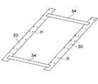
まず、図3により第1の変形例について説明する。第1の変形例においては、一対のテムプレート30同士を互いに連結する連結部材34が設けられている。これら連結部材34は、テムプレート30と略同一の鋼板材料からなり、両端がテムプレート30の上面(上梁3の上面3と接触する面と反対側の面)に固着されている。
【0031】
この第1の変形例は、トラス幅(左右の上梁間の間隔)が予め正確に分かっている場合に有用であり、テムプレート30を左右の上梁3に対して同時に取付けることができるため、乗客コンベアの改修作業をより迅速に行うことができる。
【0032】
第2の変形例
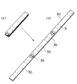
次に、図4(a)(b)により第2の変形例について説明する。図4(a)(b)に示す第2の変形例においては、3枚のテムプレート30がヒンジ機構(ちょうつがい)35により互いに連結されている。
【0033】
この第2の変形例によれば、テムプレート30は、ヒンジ機構35により互いに連結されているため、図4(a)に示すように、コンパクトに折り畳むことができ、作業現場への搬送が容易である。
【0034】
なお、互いに連結されるテムプレート30の数は3枚に限定されるものではなく、3枚より多くしても少なくしてもよい。
【0035】
第3の変形例
次に、図5により第3の変形例について説明する。図5に示す第3の変形例においては、各テムプレート30a,30b,30cの互いに隣接する長手方向端縁に、互いに嵌合可能な凹凸が形成されている。テムプレート30a,30b間に形成された凹凸の形状と、テムプレート30b,30c間に形成された凹凸の形状とは、互いに異なっている。このため第3の変形例によれば、上梁3に対してより正確にテムプレートを配置することができる。
【0036】
第4の変形例
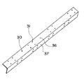
次に、図6により第4の変形例について説明する。図6に示す第4の変形例においては、テムプレート30は、L字型に折れ曲がった形状を有しており、上梁3の上面3aを覆う部分36と、上梁3の側面3bを覆う部分37とからなる。
【0037】
この第4の変形例によれば、上梁3の上面3aおよび側面3bを共に穿孔する必要がある場合、より迅速に作業を行うことができる。さらにこの場合、上梁3の上面3a用の部分36と上梁3の側面3b用の部分37とがを一体となっているため、部分36と部分37とが別体となっている場合に比べて、下孔31間の位置関係、とりわけ部分36に形成された下孔31と部分37に形成された下孔31との位置関係が正確になる。このためより正確に穿孔を行うことができる。
【0038】
第5の変形例
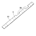
次に、図7により第5の変形例について説明する。図7に示す第5の変形例においては、テムプレート30の幅方向の端縁に加工ガイドとして切欠き38が形成されている。
【0039】
この第5の変形例によれば、上梁3の穿孔と同時に上梁3の切欠き加工を行いたい場合、切欠き38に沿って切欠き加工を行うことができる。また、この場合、加工されたボルト穴と切欠きとの位置関係を正確にすることができる。
【0040】
第6の変形例
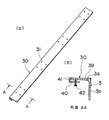
次に、図8(a)(b)により第6の変形例について説明する。図8(a)(b)に示す第6の変形例においては、テムプレート30はコの字型に形成されており、上梁3の上面3aを覆う上部39と、上部39と平行に設けられた底部40と、上部39と底部40とを連結する側部41とを有している。底部40にはテムプレート30の長手方向に沿って等間隔に複数のボルト穴が形成されており、これらボルト穴にはそれぞれボルト42が取付けられている。
【0041】
この第6の変形例によるテムプレート30を使用する場合、上梁3の上面3aの自由端側からテムプレート30を差し込み、側部41を上梁3の上面3aの自由端に当接させる。するとテムプレート30の上部39の自由端は、上面3aの幅方向の側縁と一致するようになる。この状態で、ボルト42を締付けることによりテムプレート30を上梁3に固定することができる。
【0042】
この第6の変形例によれば、テムプレート30に固定用のボルト42が設けられているため、前述したシャコ万力26等の固定手段を別途準備する必要がない。このため、テムプレート30を容易に上梁3に固定することができる。
【0043】
第7の変形例
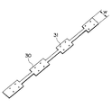
次に、図9により第7の変形例について説明する。図9に示す第7の変形例においては、テムプレート30の幅は、下穴31が形成されている部位の近傍のみで上梁3の上面3aの幅Wと同一となっており、残余の部分は切欠かれている。
【0044】
この第7の変形例によれば、テムプレート30の位置決めと穿孔作業に必要のない部分が切欠かれているため、テムプレート30全体を軽量化することができる。このためテムプレート30の作業現場への搬入を容易に行うことができる。
【0045】
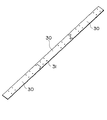
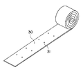
また、以上説明した第1乃至第7の変形例の他に、図10に示すように、テムプレート30を巻き取り可能な素材により形成してもよい。このようにすれば、テムプレート30の作業現場への搬入をより容易に行うことができる。この場合、テムプレート30は、例えば、強度と寸法精度を両立させることができる材料、例えば、ステンレス帯等により形成してもよい。また、テープのように上梁3の上面3aに張付け可能なものによりテムプレート30を形成してもよい。
【0046】
第2の実施の形態
次に、第2の実施の形態について説明する。図11乃至図16は本発明の第2の実施の形態を示す図である。
【0047】
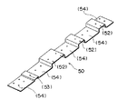
まず、第2の実施の形態において使用されるベース(取付補助枠)50について説明する。図11および図12に示すように、ベース50はプレート(基板)51と、このプレート51の上面に溶接により固着されたコの字型断面を有するベース部分(取付部)52および/または板状のベース部分(取付部)53と、を有している。
【0048】
このうち、プレート51は上梁3の上面3aと同一の幅を有する鉄板からなる。プレート51には、上面3aに既設されていた穴(例えば既設のベースを取り付けるためのボルト穴)に対応する位置にそれぞれボルト穴54が形成されている。このボルト穴54は装着されるボルトの径より若干大きくなっている。
【0049】
また、ベース部分52、53には、改修時に新たに取付けられる部材、例えば欄干を受けるホネに形成された取付用のボルト穴の位置に対応する位置に、所定のピッチで取付用のボルト穴55が形成されている。
【0050】
ベース50の全長は、持ち運びの容易さを考慮して1m以下となっている。また、ベース50のプレート51には、第1の実施の形態で説明したのと同様に、その長手方向の端縁に合いマーク55a,55bが描かれている。また、ベース50の上に「右・左」、「上から2番目」等、上梁3へのベース50の配置方法を示す文字56が記入されている(図11参照)。
【0051】
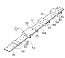
次に、このベース50を使用して上梁3を改修する方法について図11により説明する。
【0052】
まず、既設の欄干、ホネ、ベースを取外した上梁3の上面3aに対するベース50が載置される。この載置作業は、第1の実施の形態におけるテムプレート30の載置作業と同様にして行われ、上梁3に対するベース50の位置ぎめ方法も、第1の実施の形態における上梁3に対するテムプレート30の位置決め方法と同一である。
【0053】
上梁3の上面3aにベース50が載置されると、プレート51の各ボルト穴54にボルトが挿入され、ボルト締結が行われる。この場合、ボルト穴54は装着されるボルトの径より若干大きくなっているため、上面3aに形成された既設のボルト穴とプレート51のボルト穴54との間に多少の位置ずれがあっても、ボルト穴54へのボルトの挿入作業を容易に行うことができる。
【0054】
次いで、各ベース部分52、53のボルト穴55にホネが取付けられ、さらに欄干が取付けられ、乗客コンベアの改修作業が終了する。なお、図11においては省略されているが、反対側の上梁3についても同様の作業が行われる。
【0055】
以上説明したように、本実施形態によれば、上梁3に形成された既設のボルト穴を利用して改修時に上梁3に新たに取付けられるベースを取付けることができるため、上梁3に対する穿孔作業が不要となる。このため、迅速に乗客コンベアの改修作業を行うことができる。
【0056】
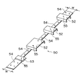
なお、第2の実施の形態においては、第1の実施の形態の場合と異なり、互いに隣接するベース50のプレート51の長手方向端縁同士を当接させる必要はなく、図13に示すように互いに隣接するプレート51の長手方向端縁が距離dをおいて離間するように、ベース50を上梁3の上面3a上に配置してもよい。この場合、ベース50の上梁3の上面3aに対する長手方向の位置決めは、例えば、上面3aに形成された既設のボルト穴とプレート51に形成されたボルト穴54とを一致させることにより行ってもよい。
【0057】
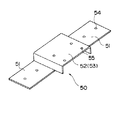
また、1枚のプレート51に対して、複数のベース部分52および/またはベース部分53を設ける必要は必ずしもしなく、図14に示すように、1枚のプレート51に1つのベース部分52または53を設けることによりベース50を作成してもよい。
【0058】
また、プレート51に、第1に実施の形態のテムプレート30に形成した下穴31と同様な下穴を形成して、プレート51にテムプレート機能を持たせてもよい。そして第1に実施の形態と同様にして、プレート51と上梁3の上面3aとを同時に穿孔してボルト穴を形成し、このボルト穴にボルトを装着してもよい。このようにすれば、例えば、上梁3の上面3aに形成された既設のボルト穴を利用するのみではプレート51と上梁3との締結点数が不足し、上梁3に対するベース50の取付強度が不足する場合に対応することが容易となる。
【0059】
なお、ベース50の形態を、以下に示す変形例の如く改変することも可能である。
【0060】
第1の変形例
まず、図15により第1の変形例について説明する。図15に示す第1の変形例においては、ベース50のプレート51の幅は、長手方向の両端近傍のみで上梁3の上面3aの幅Wと同一となっており、残余の部分はボルト穴54を形成するために必要最小限の幅となっている。この場合、上梁3の上面3aへのベース50の位置決めは、プレート51の長手方向の両端近傍部分の端縁を用いて行われる。
【0061】
この第7の変形例によれば、プレート51のうち機能上必要のない部分が取り除かれているため、ベース50全体を軽量化することができる。このためベース50の作業現場への搬入を容易に行うことができる。
【0062】
第2の変形例
次に、図16により第2の変形例について説明する。図16に示す第2の変形例においては、ベース50は一枚の鉄板を折曲げることにより形成されている。
【0063】
この第2の変形例は、ベース部分52、53をプレート51の幅からはみ出し設ける必要がない場合に有用であり、プレート51とベース部分52、53とを予め別個に形成して結合してベース50を作成する場合に比べて、低コストかつ容易にベース50を作成することができる。
【0064】
さらに第3の変形例として、プレート51の長手方向端部に、第1の実施の形態の第3の変形例(図5参照)に示すテムプレート30に形成されたような凹凸を形成して、凹凸を嵌合することにより互いに隣接するベース50間の位置決めを行うことができるように構成してもよい。
【0065】
第3の実施の形態
次に、第3の実施の形態について図17により説明する。
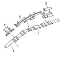
この第3の実施の形態においては、第2の実施の形態において用いられたベース50のプレート(基板)51にホネ部分(新設部品)61を直接(ベース部分52、53を使用せずに)固着したホネ構造体60が使用される。
【0066】
ホネ構造体60のプレート51には、第2の実施の形態のプレート51と同様に、上梁3の上面3aに既設されていたボルト穴に対応する位置にそれぞれボルト穴54が形成されている。
【0067】
次に、このホネ構造体60を使用して上梁3を改修する方法について説明する。
【0068】
まず、既設の欄干、ホネ、ベースを取外した上梁3の上面3aに対するホネ構造体60のプレート51が所定位置に載置される。次いで、プレート51の各ボルト穴54にボルトが挿入され、ボルト締結が行われ、これにより上梁3にホネ構造体60が固着される。次いで、ホネ構造体60のホネ部分61に欄干等の部材が取付けられ、乗客コンベアの改修作業が終了する。
【0069】
この第3の実施の形態によれば、ベースとホネとの結合工程を省略することができるため、より迅速に乗客コンベアの改修作業を行うことができる。
【0070】
【発明の効果】
以上説明したように、本発明によれば、ケガキ作業、穴開け作業、およびベースの取付作業に必要な時間を短縮することができ、乗客コンベアの改修作業の効率を大幅に向上させることができる。
【図面の簡単な説明】
【図1】本発明の第1の実施の形態を示す図であって、本体枠の上梁へのテムプレートの固定方法を示す斜視図。
【図2】本発明の第1の実施の形態を示す図であって、テムプレートの構成および上梁の穿孔方法を示す斜視図。
【図3】テムプレートの第1の変形例を示す図。
【図4】テムプレートの第2の変形例を示す図。
【図5】テムプレートの第3の変形例を示す図。
【図6】テムプレートの第4の変形例を示す図。
【図7】テムプレートの第5の変形例を示す図。
【図8】テムプレートの第6の変形例を示す図。
【図9】テムプレートの第7の変形例を示す図。
【図10】テムプレートの第8の変形例を示す図。
【図11】本発明の第2の実施の形態を示す図であって、本体枠の上梁へのベースの配置方法を示す図。
【図12】第1の実施の形態におけるベースの構成を示す図。
【図13】ベースの他の配置方法を示す図。
【図14】ベースの他の形態を示す図。
【図15】ベースの第1の変形例を示す図。
【図16】ベースの第2の変形例を示す図。
【図17】本発明の第3の実施の形態を示す図であって、本体枠の上梁へのホネ構造体の取付方法を示す図。
【図18】乗客コンベアの構造のうち、本発明の実施に係る部分を示す側面図。
【図19】本体枠の上梁へのホネの取付方法を示す図。
【図20】ベース、ホネ、欄干等を取り除いた本体枠の上梁を示す斜視図。
【図21】乗客コンベア改修時における従来の本体枠の加工方法を示す斜視図。
【図22】乗客コンベア改修時における従来の本体枠の加工方法を示す斜視図。
【符号の説明】
2 本体枠
30 テムプレート
31 下穴(加工ガイド)
38 切欠き(加工ガイド)
50 ベース(取付補助枠)
51 ベース(基板)
52、53 ベース部分(取付部)[0001]
BACKGROUND OF THE INVENTION
The present invention relates to a method for processing a main body frame in a passenger conveyor such as a so-called escalator and a moving sidewalk, a mounting auxiliary frame for mounting a part newly installed at the time of repairing the passenger conveyor, and mounting of a part newly installed at the time of repairing the passenger conveyor. With respect to methods.
[0002]
[Prior art]
An outline of the structure of the passenger conveyor is shown in FIG. As shown in FIG. 18, the passenger conveyor has a
[0003]
By the way, when the
[0004]
For this reason, in such a case, a new hole is made in the
[0005]
21 and 22 show a method of machining a bolt hole for attaching the base 1 to the
[0006]
Next, as shown in FIGS. 21 and 22, a
[0007]
[Problems to be solved by the invention]
However, since the marking work is performed for each place while looking at the drawing, it takes time to work, and the worker often makes a mistake in the marking position. In addition, when the diameter of the hole to be drilled is large, the drilling work is performed by drilling a pilot hole with a small drill blade diameter, and further repeating the drilling stepwise with a drill having a larger diameter than the pilot hole. Since it is carried out so as to obtain the hole diameter, it takes a lot of time. Furthermore, it takes time to finely adjust the position after the temporary tightening of the base 1 as well.
[0008]
The present invention has been made in consideration of the above, and can reduce the time required for marking work, drilling work, and base mounting work, and a method for processing a body frame of a passenger conveyor and a new part It is an object of the present invention to provide a mounting auxiliary frame and a method for mounting a new part.
[0009]
[Means for Solving the Problems]
To achieve this goal,The present inventionAccording to the present invention, there is provided a processing method for a main body frame of a passenger conveyor in which a tem plate is installed on a main body frame and the main body frame is processed according to a processing guide provided on the tem plate, the processing guide being attached to the main body frame. A pilot hole with a hole diameter smaller than the hole diameter to be drilledHaveWhen processing the main body frame, there is provided a processing method for a main body frame of a passenger conveyor, wherein a drill tip is brought into contact with the pilot hole and the main body frame is perforated together with the tem plate.
[0010]
The present inventionAccording to the above, by boring the body frame together with the tem plate, the bolt holes for attaching the members can be easily formed with high accuracy.
[0011]
GoodMore preferably, the tem plate has the same width as the beam constituting the main body frame.
[0013]
GoodPreferablyThe tem plate further has a notch formed at an edge of the tem plate as the processing guide,When processing the main body frame, notch processing is performed along the notch.
[0016]
DETAILED DESCRIPTION OF THE INVENTION
Embodiments of the present invention will be described below with reference to the drawings.
First embodiment
First, the first embodiment will be described. 1 to 10 are views showing a first embodiment of the present invention.
[0017]
First, the
[0018]
In the
[0019]
Further, as shown in FIG. 1, the
[0020]
Next, a method for repairing a passenger conveyor using the
[0021]
First, the
[0022]
In performing the fixing work of the
[0023]
When positioning of the
[0024]
Further, the
[0025]
When the attachment work of the
[0026]
Next, a newly installed member, for example, the base 1 is placed on the
[0027]
As described above, according to the present embodiment, the
[0028]
In the present embodiment described above, the
[0029]
Further, in the present embodiment described above, the
[0030]
First modification
First, a first modification will be described with reference to FIG. In the first modification, a connecting
[0031]
This first modification is useful when the truss width (interval between the left and right upper beams) is accurately known in advance, and the
[0032]
Second modification
Next, a second modification will be described with reference to FIGS. In the second modification shown in FIGS. 4A and 4B, three tem
[0033]
According to the second modification, the
[0034]
Note that the number of
[0035]
Third modification
Next, a third modification will be described with reference to FIG. In the third modification shown in FIG. 5, concavities and convexities that can be fitted to each other are formed at the longitudinal edges of the
[0036]
Fourth modification
Next, a fourth modification will be described with reference to FIG. In the fourth modification shown in FIG. 6, the
[0037]
According to the fourth modified example, when it is necessary to drill both the
[0038]
Fifth modification
Next, a fifth modification will be described with reference to FIG. In the fifth modification shown in FIG. 7, a
[0039]
According to this fifth modification, when it is desired to perform notch machining of the
[0040]
Sixth modification
Next, a sixth modification will be described with reference to FIGS. In the sixth modification shown in FIGS. 8A and 8B, the
[0041]
When the
[0042]
According to the sixth modification, since the fixing
[0043]
Seventh modification
Next, a seventh modification will be described with reference to FIG. In the seventh modification shown in FIG. 9, the width of the
[0044]
According to the seventh modified example, since the portion unnecessary for positioning and drilling work of the
[0045]
In addition to the first to seventh modified examples described above, the
[0046]
Second embodiment
Next, a second embodiment will be described. 11 to 16 are views showing a second embodiment of the present invention.
[0047]
First, the base (attachment auxiliary frame) 50 used in the second embodiment will be described. As shown in FIGS. 11 and 12, the
[0048]
Among these, the
[0049]
Further, the
[0050]
The total length of the
[0051]
Next, a method for repairing the
[0052]
First, the
[0053]
When the
[0054]
Next, a hook is attached to the
[0055]
As described above, according to the present embodiment, a base that is newly attached to the
[0056]
In the second embodiment, unlike the case of the first embodiment, it is not necessary to make the longitudinal edges of the
[0057]
Further, it is not always necessary to provide a plurality of
[0058]
Alternatively, the
[0059]
The form of the base 50 can be modified as shown in the following modification examples.
[0060]
First modification
First, a first modification will be described with reference to FIG. In the first modification shown in FIG. 15, the width of the
[0061]
According to the seventh modification, the portion of the
[0062]
Second modification
Next, a second modification will be described with reference to FIG. In the second modification shown in FIG. 16, the
[0063]
This second modification is useful when the
[0064]
Further, as a third modified example, unevenness as formed in the
[0065]
Third embodiment
Next, a third embodiment will be described with reference to FIG.
In the third embodiment, a horn portion (new component) 61 is directly attached to the plate (substrate) 51 of the base 50 used in the second embodiment (without using the
[0066]
Bolt holes 54 are formed in the
[0067]
Next, a method for repairing the
[0068]
First, the
[0069]
According to this 3rd Embodiment, since the joint process of a base and a horn can be abbreviate | omitted, a passenger conveyor repair work can be performed more rapidly.
[0070]
【The invention's effect】
As described above, according to the present invention, it is possible to shorten the time required for marking work, drilling work, and base mounting work, and to greatly improve the efficiency of passenger conveyor repair work. .
[Brief description of the drawings]
FIG. 1 is a perspective view showing a first embodiment of the present invention and a method of fixing a tem plate to an upper beam of a main body frame.
FIG. 2 is a diagram showing a first embodiment of the present invention, and is a perspective view showing a structure of a tem plate and a method for drilling an upper beam.
FIG. 3 is a view showing a first modification of the tem plate.
FIG. 4 is a view showing a second modification of the tem plate.
FIG. 5 is a view showing a third modification of the tem plate.
FIG. 6 is a view showing a fourth modification of the tem plate.
FIG. 7 is a view showing a fifth modification of the tem plate.
FIG. 8 is a view showing a sixth modification of the tem plate.
FIG. 9 is a view showing a seventh modification of the tem plate.
FIG. 10 is a view showing an eighth modification of the tem plate.
FIG. 11 is a diagram showing a second embodiment of the present invention and a method for arranging a base on an upper beam of a main body frame;
FIG. 12 is a diagram showing a configuration of a base in the first embodiment.
FIG. 13 is a view showing another arrangement method of the base.
FIG. 14 is a diagram showing another form of the base.
FIG. 15 is a diagram showing a first modification of the base.
FIG. 16 is a diagram showing a second modification of the base.
FIG. 17 is a view showing a third embodiment of the present invention and showing a method for attaching a horn structure to an upper beam of a main body frame.
FIG. 18 is a side view showing a part of the passenger conveyor structure according to the embodiment of the present invention.
FIG. 19 is a view showing a method of attaching a horn to an upper beam of a main body frame.
FIG. 20 is a perspective view showing the upper beam of the main body frame from which the base, horn, balustrade and the like are removed.
FIG. 21 is a perspective view showing a conventional method for processing a main body frame when a passenger conveyor is repaired.
FIG. 22 is a perspective view showing a conventional method of processing a main body frame when a passenger conveyor is repaired.
[Explanation of symbols]
2 Body frame
30 tem plate
31 Pilot hole (machining guide)
38 Notch (machining guide)
50 base (mounting auxiliary frame)
51 Base (substrate)
52, 53 Base part (mounting part)
Claims (3)
前記加工ガイドは、前記本体枠に穿孔される穴径より小さい穴径を有する下穴を有し、前記本体枠を加工する場合、前記下穴にドリルの刃先を当接させ、前記テムプレートごと本体枠を穿孔することを特徴とする乗客コンベアの本体枠の加工方法。A method for processing a body frame of a passenger conveyor that installs a tem plate on a body frame and processes the body frame according to a processing guide provided on the tem plate,
The processing guide has a prepared hole having a smaller hole diameter than the diameter to be drilled on the body frame, when processing said body frame, is brought into contact with the cutting edge of the drill into the prepared hole, each said Temu plate A method for processing a body frame of a passenger conveyor, wherein the body frame is perforated.
Priority Applications (1)
| Application Number | Priority Date | Filing Date | Title |
|---|---|---|---|
| JP26488396A JP4040710B2 (en) | 1996-10-04 | 1996-10-04 | Processing method for passenger conveyor body frame |
Applications Claiming Priority (1)
| Application Number | Priority Date | Filing Date | Title |
|---|---|---|---|
| JP26488396A JP4040710B2 (en) | 1996-10-04 | 1996-10-04 | Processing method for passenger conveyor body frame |
Publications (2)
| Publication Number | Publication Date |
|---|---|
| JPH10109209A JPH10109209A (en) | 1998-04-28 |
| JP4040710B2 true JP4040710B2 (en) | 2008-01-30 |
Family
ID=17409557
Family Applications (1)
| Application Number | Title | Priority Date | Filing Date |
|---|---|---|---|
| JP26488396A Expired - Fee Related JP4040710B2 (en) | 1996-10-04 | 1996-10-04 | Processing method for passenger conveyor body frame |
Country Status (1)
| Country | Link |
|---|---|
| JP (1) | JP4040710B2 (en) |
Families Citing this family (2)
| Publication number | Priority date | Publication date | Assignee | Title |
|---|---|---|---|---|
| JP4857970B2 (en) * | 2006-07-12 | 2012-01-18 | 三菱電機株式会社 | Elevator fall prevention curtain mounting device and mounting method |
| JP7693128B2 (en) * | 2022-10-24 | 2025-06-16 | 三菱電機ビルソリューションズ株式会社 | Processing position specifying device for passenger conveyor, processing position specifying device set, and processing method for passenger conveyor |
-
1996
- 1996-10-04 JP JP26488396A patent/JP4040710B2/en not_active Expired - Fee Related
Also Published As
| Publication number | Publication date |
|---|---|
| JPH10109209A (en) | 1998-04-28 |
Similar Documents
| Publication | Publication Date | Title |
|---|---|---|
| JP4644750B1 (en) | Welding jig and welding method using the same | |
| JP4040710B2 (en) | Processing method for passenger conveyor body frame | |
| CA2469249C (en) | Building framework, method for making the same and components used in the framework | |
| CN100537347C (en) | rib pull-in method | |
| US20050138871A1 (en) | Method and apparatus for locating hole positions on an adjustable stair stringer | |
| US5662150A (en) | Method of drilling true elongated holes in wood members | |
| JPH01252482A (en) | Elevator guide rail installation device | |
| JP2532354Y2 (en) | Anchor bolt positioning jig | |
| KR102478556B1 (en) | Triangle and bending method of frame using it | |
| KR980007964U (en) | Automobile Rear Floor Panel Bumper Mounting Hole Inspection Structure | |
| JP2000264580A (en) | Overhead crane saddle and girder coupling device | |
| JPH07215626A (en) | Elevator template | |
| JP3145303U (en) | Ceiling board auxiliary support | |
| JPH05319363A (en) | Large unit assembly method | |
| CN212295251U (en) | Steel bar truss floor support plate | |
| JPH08219541A (en) | Air conditioner installation plate for window installation | |
| CN116357101B (en) | Positioning Pre-control Components and Positioning Pre-control Methods for Aluminum Panel Curtain Walls | |
| JPH0649892A (en) | Attaching structure of balcony | |
| JP3028476B2 (en) | Method of repairing tunnel interior plate mounting portion and repair member | |
| JPH0111369Y2 (en) | ||
| US20020010997A1 (en) | Compromise rail | |
| JPH094141A (en) | Fixture for folded plate and hanging method thereof | |
| KR960008849Y1 (en) | Scaffold board | |
| JP3007623B1 (en) | Ruler for centering and scoring of pipe hole | |
| JPH1061137A (en) | String |
Legal Events
| Date | Code | Title | Description |
|---|---|---|---|
| A977 | Report on retrieval |
Free format text: JAPANESE INTERMEDIATE CODE: A971007 Effective date: 20051212 |
|
| A131 | Notification of reasons for refusal |
Free format text: JAPANESE INTERMEDIATE CODE: A131 Effective date: 20051220 |
|
| A521 | Written amendment |
Free format text: JAPANESE INTERMEDIATE CODE: A523 Effective date: 20060215 |
|
| A02 | Decision of refusal |
Free format text: JAPANESE INTERMEDIATE CODE: A02 Effective date: 20060509 |
|
| A521 | Written amendment |
Free format text: JAPANESE INTERMEDIATE CODE: A523 Effective date: 20060710 |
|
| A521 | Written amendment |
Free format text: JAPANESE INTERMEDIATE CODE: A821 Effective date: 20060821 |
|
| A911 | Transfer of reconsideration by examiner before appeal (zenchi) |
Free format text: JAPANESE INTERMEDIATE CODE: A911 Effective date: 20060915 |
|
| A131 | Notification of reasons for refusal |
Free format text: JAPANESE INTERMEDIATE CODE: A131 Effective date: 20070814 |
|
| A521 | Written amendment |
Free format text: JAPANESE INTERMEDIATE CODE: A523 Effective date: 20071004 |
|
| TRDD | Decision of grant or rejection written | ||
| A01 | Written decision to grant a patent or to grant a registration (utility model) |
Free format text: JAPANESE INTERMEDIATE CODE: A01 Effective date: 20071030 |
|
| A61 | First payment of annual fees (during grant procedure) |
Free format text: JAPANESE INTERMEDIATE CODE: A61 Effective date: 20071108 |
|
| FPAY | Renewal fee payment (event date is renewal date of database) |
Free format text: PAYMENT UNTIL: 20101116 Year of fee payment: 3 |
|
| R150 | Certificate of patent or registration of utility model |
Free format text: JAPANESE INTERMEDIATE CODE: R150 |
|
| FPAY | Renewal fee payment (event date is renewal date of database) |
Free format text: PAYMENT UNTIL: 20101116 Year of fee payment: 3 |
|
| FPAY | Renewal fee payment (event date is renewal date of database) |
Free format text: PAYMENT UNTIL: 20111116 Year of fee payment: 4 |
|
| FPAY | Renewal fee payment (event date is renewal date of database) |
Free format text: PAYMENT UNTIL: 20121116 Year of fee payment: 5 |
|
| FPAY | Renewal fee payment (event date is renewal date of database) |
Free format text: PAYMENT UNTIL: 20121116 Year of fee payment: 5 |
|
| FPAY | Renewal fee payment (event date is renewal date of database) |
Free format text: PAYMENT UNTIL: 20131116 Year of fee payment: 6 |
|
| S531 | Written request for registration of change of domicile |
Free format text: JAPANESE INTERMEDIATE CODE: R313531 |
|
| R350 | Written notification of registration of transfer |
Free format text: JAPANESE INTERMEDIATE CODE: R350 |
|
| LAPS | Cancellation because of no payment of annual fees |

