JP4038562B2 - Bullet ball machine - Google Patents
Bullet ball machine Download PDFInfo
- Publication number
- JP4038562B2 JP4038562B2 JP08440697A JP8440697A JP4038562B2 JP 4038562 B2 JP4038562 B2 JP 4038562B2 JP 08440697 A JP08440697 A JP 08440697A JP 8440697 A JP8440697 A JP 8440697A JP 4038562 B2 JP4038562 B2 JP 4038562B2
- Authority
- JP
- Japan
- Prior art keywords
- ball
- game
- launch
- game ball
- cam
- Prior art date
- Legal status (The legal status is an assumption and is not a legal conclusion. Google has not performed a legal analysis and makes no representation as to the accuracy of the status listed.)
- Expired - Lifetime
Links
Images


Landscapes
- Pinball Game Machines (AREA)
Description
【0001】
【発明の属する技術分野】
本発明は、パチンコ機やアレンジボール遊技機、じゃん球遊技機等の弾球遊技機の技術分野に属する。
【0002】
【従来の技術】
回転する発射カムにより発射槌を傾動させて遊技球を発射し、また発射槌の傾動によりこの発射槌に付けてあるハンドル小物で遊技球を発射位置に供給するようにした遊技球供給方法はパチンコ機は特公平2−35586号公報ですでに公知である。
また、遊技球をカウントする装置はソレノイドで球受器を作動させ、球受器内部に遊技球が存在するかの検知システムであり、アレンジボール遊技機やじやん球遊技機で利用されている。
【0003】
【発明が解決しようとする課題】
しかしながら、従来のパチンコ機の発射装置は、モータ側に設けられる発射カムと発射槌に設けられたローラーアームとの係脱関係で、発射槌が遊技球を発射した瞬間に発射槌に付けてある引バネで発射槌が元の位置に復帰するようになっているので、復帰したときに発射槌は勢い剰ってバウンドをする。
このバウンドを極力抑えるために2個の防振ゴムが設けてある、この防振ゴムもパチンコ機の稼働が多くなるとゴム自体が劣化すると共に変形してくることは周知のことである。
防振ゴムの変形劣化進行で発射槌のバウンドも大きくなり、バウンドした瞬間にハンドル小物(詳細後述)が玉送レバー(通称ケタクリとも言って1例として図8の86に示す)を叩くことになり、球送レバーを振動させて球送り(以後アヒルと称し1球づつ構造内部に形成された凹部に加えて下に落とす式で、1例として図8の82に示す)を作動させ1球を送り出す。
したがって、次の遊技球を発射点に送り出しを行うとき、発射槌の傾動が始まるとハンドル小物が玉送装置を作動させて遊技球を発射点に送り出しをして、結果発射点には2個の遊技球が並ぶという欠点が生じてくる。
また、遊技球のカウントが槌の振動によってアヒルが作動し1個であるべき所を2個とカウントすることがあった。
【0004】
上述のように、従来のパチンコ機では遊技球発射装置の駆動状態と球送装置の作動状態とがうまく調節してあっても時間の経過に伴って位置決防振ゴム、衝撃吸収ゴムや引バネ等の劣化で規則正しく的確に安定した遊技球の発射点への供給が得られず、遊技球の良い飛び状態が保てなくなる。
これは発射槌がバウンドで補給された遊技球を少し叩く、つまり、補給されたときにバウンドした槌先でタイミングが合って遊技球と槌先とが接触して遊技球を発射方向に飛び出させ、実際の発射の際にはタイミングが合わずに遊技球が安定停止していないので球飛びの不良と言う結果になる。
この調整には、位置決防振ゴム、衝撃吸収ゴムの交換または位置決防振ゴムの位置調整や玉送りレバーを作動させるハンドル小物の角度調整等の作業を遊技場ではしなくてはならないという欠点である。
また、生産工場でも熟練した技術者が初期時の調整が必要である。
【0005】
図8でより詳しく説明すると、発射装置81と玉送装置80とで遊技球97を発射する為の装置であり、発射装置81には発射モータ92が取り付けられその発射モータ92には回転軸95があってその回転軸95に発射カム85が設けられ、遊技球の21の発射に際し回転軸95は時計方向に回転をする。
発射装置81は、図示しない発射ダイアルに付けられ、その発射ダイアルには図示しない心棒で巻プーリー93が付けられている。
巻プーリー93は、引バネ89とワイア96で発射力調整器90に接続され発射力調整器90は発射力の微調整をする目的で設けられている。
発射ダイアルを図8に示す反時計方向に廻すと発射が開始され更に廻すと発射強度が増して飛び距離がのびる。
玉送装置80にはアヒル82が付けられ玉送レバー86がアヒル82の底面に当たる位置に設けられている。
発射装置81には発射槌83が付けてありその発射槌83は引バネ89で矢印R方向に付勢され、発射槌83は、位置決防振ゴム88と衝撃吸収ゴム91と共同して定められた角度に定着している。
発射カム85の回転でその頂点が発射槌83のローラーアーム94に達すると発射槌83は矢印D方向で点線図で示す発射槌84まで回動させ、更に発射カム85が回転を重ねると、ローラーアーム94が発射カム85の頂点から外れて付勢されている引バネ89によって矢印P方向に反発して遊技球97を飛ばす。
【0006】
発射槌83にはハンドル小物87が付けられており、発射槌83が移動をするとハンドル小物87が玉送レバー86を作動させ、それにつれてアヒル82が動き遊技球97を加え込む、発射槌83が矢印P方向へ反発するとアヒル82に加えた遊技球97を図示しない発射点に供給する。発射動作はこの繰り返しで順次発射点に遊技球97を供給しながら連続的に発射ができる。
このとき、発射槌83が反発戻りをしたときに位置決防振ゴム88と衝撃吸収ゴム91とで発射槌83のバウンドを抑えているがゴムの性質上劣化してくることや、取付位置の調整が不備であったら発射槌83のバウンドも大きくなりハンドル小物87がアヒル82を作動させて再び遊技球97を送り出してしまうこととなる。
次に発射カム85が回って発射槌83は矢印D方向に移動して次の遊技球97を送り出し、結局発射点には2個の遊技球97が並んで発射作動すれば当然ながら望む位置に遊技球97は飛ばない。
また、球送装置80が図示しない上皿の裏側に設けると上皿自体が開閉可能にしてありその支点にばらつきとガタがあって、完全固定ができないと言う不安定要素があるので球送レバー86とハンドル小物87との係脱関係が定位置にならないと言う欠点もある。
【0007】
以上が従来から抱えている欠点で、このことは、遊技上の勝運の無い遊技客が苛立つ気持ちで上皿を持ち上げたり押し下げたりしてして歪みが生じて送りのタイミングが狂っていしまい、調整をしない限り遊技球を2個送りや、遊技球を少し叩いて遊技球を発射方向に飛び出させ、実際の発射の際には遊技球の座りば悪いので球飛びの不良等による調整の必要も無い発射装置の提供を目的とする。
次に遊技客が自動打ち(発射調節レバーに異物を咬まして固定し、その発射ダイアルとガラス枠との間を針金等で接続させる)をしていて遊技球が無くなったときに、遊技をしていた遊技機よりその遊技客が立ち去ったら自動打ちを止めない限り発射動作は止まらない、これはこの遊技機の電源を遮断か、ハンドルを戻す等のことをしない限り発射動作の停止はしない。
【0008】
次に一般パチンコ機で発射される遊技球をカウントすることは、普通考えられていない。
例えば第一種特別電動役物付遊技機(以後第一種パチンコ機と称す)で大当たりとなって大入賞口が開放して遊技の特賞が得られ、多量の賞品球である遊技球の獲得ができる場合、大入賞口は一回の開放でおおむね10球単位で6秒の開放時間となり、16回の大入賞口の開放ができて160個の入賞球が得られる。
各開放毎の間にインターバルタイマが設けてあり、大当たりの発生から16回目の大入賞口の閉鎖までの時間が、発射個数が毎分100球として、インターバルタイマが4秒とした場合は、
大入賞口の開放合計時間は、16×6=96秒、
インターバルタイマは、15×4=60秒、
大入賞口開放時間とインターバルタイマを加算で、60+96=156秒、
大入賞口の賞球数が15個とした場合で総払出個数は、
160×15=2400個で、156秒間に打ち込まれる遊技球は、
156×100÷60=260、総獲得球数は、2400−260=2140個となるが、開放される大入賞口に全て入賞した場合であって、この開放している大入賞口に入らない遊技球がある。
この大当たり中に大入賞口に入賞できなかった遊技球の個数が多ければ総獲得球数が減ってくる、つまり、出玉が2400個と一定で打ち込み数260個を最小で時間が増えればこの260個が増える結果になり総出玉の減少となる。
遊技場経営の原点と言うべき釘調整を上述したデータがないとこの把握と対策ができず未だ持って感にたよっているものである。
尚、上記の計算は、他の入賞口に入賞をみなく単に大入賞口のみを考えた場合を示したものである。
かかる上記の欠点に鑑み本発明はなされたもので次にこの解決策を述べる。
【0009】
【課題を解決するための手段】
請求項1の弾球遊技機は、遊技盤と、該遊技盤を着脱可能に固定でき下部には発射レールが固着されたプレートと、該発射レールの発射点に遊技球を補給する球送装置と、前記発射レールに補給された遊技球を前記遊技盤に向けて発射する発射装置とを備える弾球遊技機において、前記発射装置には該発射装置の駆動源に由来する動力を前記球送装置へ伝達するための動力伝達装置を設け、前記球送装置には、上皿より遊技球が供給される球通路と、前記動力伝達装置に接続されて前記発射装置と同期回転し前記球通路にある遊技球を窪みに装填して補給口より前記発射レールへ導く送カムとを設け、前記プレートには前記発射レールの発射点の近傍に凹部である取付部を設け、該取付部に前記球送装置を着脱可能に取り付け、
前記動力伝達装置は、前記駆動源である発射モータ側の発射カム軸に取り付けられて発射カムと供回りする駆動ギアと、前記送カムと接続されて供回りする送軸に設けられた追従ギアと、前記駆動ギアと追従ギアとに掛けられたタイミングベルトとを備えてなり、
前記送カムは前記送軸に対してスプリングで付勢圧着されたラチェット機構によるブレーキ構造で前記送軸と接続されており、
前記球送装置から送出された遊技球の通過を検出する遊技球検出装置を設け、
該球検出装置が遊技球を検出しないときは設定時間後に前記発射装置を停止させる構成とした
ことを特徴とする。
プレートに球送装置を設けることで発射装置と球送装置とが遊技盤に対し遊技盤と直線上の完全固定となり、安定した玉送りができる。
球送装置をプレートの凹部に取り付けるので発射レールを覆わないから、発射レールの清掃がしにくくならない。
【0010】
球送装置を上皿の裏側に設けると上皿自体が開閉可能で支点に製造上のばらつきとガタがあって、このことが不安定要素となっていた。
従来プレートは内枠に付けられその内枠に遊技盤を固定するものである。
そのプレートは、遊技盤に合う厚みが設けてありその内部は中空で有効利用していない。
プレートの発射点の位置する近傍に球送装置が取り付けられる凹部を設けて、その凹部に球送装置を着脱可能に取り付け、安定固定をするようにしたので、発射レールの清掃が従来通りでしかもプレートに固定であるので稼働中に玉送りが狂ってくることもなくなる。
【0011】
前記動力伝達装置は、前記駆動源である発射モータ側の発射カム軸に取り付けられて発射カムと供回りする駆動ギアと、前記送カムと接続されて供回りする送軸に設けられた追従ギアと、前記駆動ギアと追従ギアとに掛けられたタイミングベルトとを備えてなり、
前記送カムは前記送軸に対してスプリングで付勢圧着されたラチェット機構によるブレーキ構造で前記送軸と接続されており、前記送カムは前記送軸に対してスプリングで付勢圧着されたラチェット機構によるブレーキ構造で前記送軸と接続されている。
駆動ギア、追従ギア及びタイミングベルトによって発射カム軸の動力が送カムに伝達されるから、発射カムの回転(発射)と送カムの回転(補給)との同期回転が正確になる。球送装置から発射レールに補給された遊技球が安定停止したときに発射ができるタイミングに設定することが可能になる。
【0012】
前述のようにレバーを利用するとレバーの摺動面の磨耗でレバーに当たるタイミングが遅れるようになる。これは時々レバーに当たる他の部品の形状を変化させて調整をしなければならない。調整を誤って間隔を小さくすると作動タイミングが早くなり、間隔を広くすると作動タイミングが遅れるようになる。
この欠点の解消には、モータの軸からシャフトやベルトで球送装置を動作させるようにすることは、シャフトドライブであればギァーを使用して、ベルトであればタイミングベルトを使用する、このようにすれば自然と同期がとれてしかも滑らかで安定した玉送りができるようになる。
これ以外にも伝達方向が自在なワイアで構成とすることも可能で、モータ軸と球送装置の回転体との間をこのワイアで接続させれば尚一層簡単に構成することができる。
また、この他にも球送装置をモータまたはロータリーソレノイドで回転させる方法も考えられ、発射モータと電気的に同期を採って作動させればよい。
【0013】
また、前記球送装置から送出された遊技球の通過を検出する遊技球検出装置を設け、該球検出装置が遊技球を検出しないときは設定時間後に前記発射装置を停止させる構成としてある。
動力伝達装置の故障により球送りができなくなると言う場合が考えられれ、遊技球検出装置を設けると、発射を促しているにも拘わらず遊技球検出装置が遊技球を検出しないときは球送装置の故障とみることが可能となる。
また、遊技球検出装置を設けると遊技客が自動打ちをしていて遊技を中断して球送装置内に遊技球がないときには、無駄に発射装置を動かすこととなる、遊技球をある時間経ても検出できないときに遊技球検出装置を設けることで発射装置を止めることが可能である。
遊技球検出装置の活用方法の次の例としては、発射と球送と同期を採っているのでモータの定点停止をさせることも可能で、発射中にこの発射を止める場合を考えれば遊技球を検出した時点でモータへの通電を止めると、発射槌が発射し終えた時点であるから再起動させるときはモータに負担が掛からない。
以上の構成であればモータが約半回転してモータ軸の発射カムが発射槌のローラアームに接触開始する位置になる。
【0014】
次に、遊技球検出装置を設けることはアレンジボール遊技機やじやん球遊技機等の発射個数をカウントする遊技機に於いても有効に利用することができる。
このことは、アレンジボール遊技機やじやん球遊技機等とパチンコ機との枠装置の共用ができると言うことである。
前述の欠点で述べた発射球のカウントは、第一種パチンコ機の遊技球検出装置で発射球をカウントして大当たりのとき入賞球数と発射球数で何個入球できなかったかを見ることができるので、総獲得球数が少しでも少ないと遊技客は不満であり、良い遊技機と悪い遊技機の目安とするとき、この数値、つまり入賞個数に対して総発射数の差値で決まる。
第一種パチンコ機等の時間的に開放される入賞口を備えた遊技機の設計には、この差値を頼りに遊技釘の位置をきめることができるし、パチンコ店に於いても遊技客の誘致で釘調整の確固たるデータの参考にすることもできる。
遊技球検出装置は従来から公知となっている遊技球で押す等の一時停止検出形式やアヒル形式で遊技球を検出する方法と違って等速通過方式を採用しているので欠けた遊技球や変形した遊技球でも検出が可能であり球詰まり等が起きない。
【0015】
また従来の遊技球検出装置で遊技球を押す等の一時停止検出形式では、遊技球を検出する方法の遊技球の検出で遊技球検出スイッチまたは遊技球検出センサを利用したときに、その遊技球検出スイッチまたは遊技球検出センサには検出範囲であるデューティ間隔の制限があるのでやはり欠けた遊技球や変形した遊技球の検出ができないときがある。アヒル形式では、その動きが往復運動であるのでバウンドによる過剰カウントが発生するし、アヒル式はソレノイドで駆動させる方式もあるがその磨耗が激しくアヒルと言う部品の交換や球送装置自体の交換を余儀なくさせられることもある。
なぜアヒルの磨耗があるかと言えば、ソレノイドの動作はだれでもわかるようにその動作はソレノイドに通電と非通電するとハンマーで叩いたような衝撃がソレノイドで生成され、その衝撃をアヒルと遊技球に与えられ、遊技球の重量でのそ数倍の惰性が生じる。
この惰性で発生する衝撃とソレノイド自身の衝撃でソレノイドに連動するすべての部品は磨耗してくる結果になる。
上述のよう遊技球の検出には、他の遊技球検出方法と比較して等速通過式が最も優れた効果が得られるものである。
【0016】
球送装置の取付方法は、取付部となる凹部にピンを設けると共に球送装置にも前記ピンに対する穴を設けて球送装置を前記ピンに装填する構成とできる。
プレートの凹部の特定の位置にプレートと同質のピンを設けて、このピンはテーパー状にして球送装置にもこのピンの対形にテーパー状の穴のあいた筒を球送装置と同質で設け球送装置のテーパー穴とプレート側のテーパーピンとを連通させるように押し込めば容易に安定固定ができる。
振動で球送装置の脱落の可能性もあるが脱落防止の止め金を設けてもよく、プレート側に蓋を設ければこの脱落防止もできる。
【0017】
【発明の実施の形態】
次に本発明の構成を一層明確にするために好適な実施例を図面と共に説明することにする。
尚、本発明の実施の形態は、下記の実施例に何ら限定されるものではなく、技術的範囲に属する限り種々の形態で本発明を採用することができる。
【0018】
【実施例】
以下に本発明の実施例を図面と共に説明する。
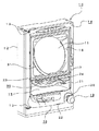
図1は本発明の遊技機取り付けられる球送装置を採用した遊技機本体を示す斜視図である。
本実施例の遊技機10には図示しない遊技機設置島に設置され釘等で打ち止め固定される外枠12を装備して、その外枠12の左辺外側にはヒンジ13が上下に設けられている。
外枠12のヒンジ13には、内枠14にも対する形のヒンジ13が設けられ、その上下のヒンジ13を支軸に外枠12に対向して開閉可能に設けられている。
内枠14には、詳細を図示しない各種入賞口や障害釘等を配設し誘導レール31等を敷設した遊技盤11が脱着可能に取り付けられている。
内枠14には、金枠17が取り付けられその金枠17の内側にはガラス枠18が金枠17の内側左辺を支軸にして開閉可能に取り付けられている。
内枠14の前下部には、上皿15(前機構盤とも表現することがある)と下皿16及び発射ハンドル19が取り付けられ、その発射ハンドル19の外周には発射調節レバー20が回動可能に取り付けられている。
上皿15の左側には、賞球放出口39が開口している。
発射ハンドル19の内部には詳細を図示しない発射調節レバー20に連動するようにした発射作動スイッチが設けられており、遊技球24を上皿15に投入して発射調節レバー20を時計方向に回せば発射作動スイッチがONとなり発射が開始される。
発射調節レバー20を更に時計方向に回せば発射力が上昇して遊技球24を誘導レール31に沿って遊技盤右側方向に強く飛ばすことができる。
【0019】
遊技球24を遊技盤11に発射していると、遊技盤11に設けられている各種入賞口に時折入賞することがあり、入賞すれば遊技球24が賞品球として賞球放出口39を通って上皿15に放出される。
詳細を述べない大当たり等で入賞が多く続くと遊技球24が多く上皿15に賞品球として遊技球24が放出され、更に入賞が続けば遊技球24は詳細を図示しない導通路を経て下皿16にあふれる。また更にあふれが続くと下皿16が満杯になり、図2で示す満杯検知スイッチ36が働いて発射を止める。
発射が停止したときに、その状況を示すための満杯表示23が設けられているのでこの表示も行われ、この満杯表示23を設けることで遊技客は発射の停止がなぜ行われたかを知ることができる。
上皿15には上球抜レバー21が設けられておりこの上球抜レバー21を操作すると上皿15にある遊技球24は詳細を図示しない通路を通って下皿16に導くことができる。
下皿16には下球抜レバー22が付けられており、下皿16の下に図示しない球箱を置いて下球抜レバー22を操作すれば下皿16に保有している遊技球24は球箱に抜き取ることができる。
【0020】
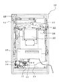
図2は遊技機10の裏側を示す背面図である。
遊技盤11の裏側には、遊技盤11を内枠14とで固定するための機構盤25が設けられ、この機構盤25を外すと遊技盤11を取り出すことができる。
機構盤25には図1で一部説明した満杯検知スイッチ36が設けられている。
機構盤25の上部には球タンク29が備えられ内部には遊技球24を保有し、次に続く中継樋32で詳細を図示しない賞球放出装置26に接続されている。
したがって、遊技盤11の入賞口に遊技球24が入賞すると賞球放出装置26が作動して賞品球として遊技球24が上皿15に放出され、次に遊技球24は球タンク29からタンクレール30と中継樋32を介して遊技球24を賞球放出装置26に補充される。
内枠14裏面下部には、図3で示す発射槌28を付けた発射装置27が機構盤25の下に位置して発射装置基台71により取り付けられている。
機構盤25には、内枠制御装置35が設けられ、発射制御や賞球放出制御を行っている。
【0021】
内枠制御装置35は、前述したように発射調節レバー20を時計方向に回せば内枠制御装置35が作動して遊技球24の発射ができるように構成されている。
発射した遊技球24は遊技盤11遊技機10の内部を通って機構盤25の下に設けられたアウト球放出口33より図示しない遊技機設置島内部に放出される。
【0022】
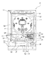
図3は遊技機10のガラス枠18と上皿15を開放した図で、破断線A、A’は図4に於いてその内容を示す。
上皿15は上皿支軸62を支軸にして開閉可能で、図7に示すキャッチ63で常時固定され、このキャッチ63を操作すれば上皿15は開放される。
内枠14にはプレート40が取り付けられ、そのプレート40には発射レール37が取り付けられている。
プレート40は遊技盤11を保持固定するために設けられその遊技盤11と同じ厚みを有して内部は骨組みはあるものの空洞になっている。
プレートの右側には空洞分の取付部である凹部45が設けられ、この凹部45に球送装置38がはめ込まれている。
球送装置38には送カム42が設置され図6で詳細を述べる発射動作に同期して送カム42が反時計方向に回転して、球通路67を遊技球24が転動してそのまま通って送カム42に導き入れる。
更に送カム42が回転すると遊技球24は発射レール37に装填され、発射槌28で発射方向に叩けば遊技球24の発射となる。
【0023】
球送装置38には球検出装置43が設けられていて回転する送カム42にある遊技球24が通過すると詳細を述べない球検出信号として内枠制御装置35に送られ遊技球数のカウントや発射停止の定点停止の制御を行っている。
発射は、発射槌28を引バネ53で反発射方向に付勢されていて詳細を述べない発射モータ34に設けられる発射カムとの係脱で遊技球24の発射ができる。
発射調節レバー20の軸後部には詳細を後述するダイアルプーリ41が付けられている。
【0024】
図4は図3のA、A’破断右側面図である。
発射装置27には球送装置38への動力伝達するための動力伝達装置69が設けられ、その動力伝達装置69に追従軸受70を介して送軸46が貫入されている。
続いて図5は、球送装置38分解図で(a)は筺体蓋49を除いた図であり(b)は球送装置38(a)のy、y’の破断線で内部状況を示す図である。
(c)は球送装置38の筺体蓋49で(d)はその側面図である。
送カム42は(b)に示すように送カムa42a、送カムb42bとで構成されカム止ビス42cで固定されていて筺体48に対してルーズで筺体蓋49によって脱落を防いでいる。
送カム42の中心に多角形のカム孔47が開けられ図4と図6で示す送軸46が挿入される穴である。
したがって送軸46と送カム42とが接続して送軸46が回転すると送カム42も回転をする。
(c)、(d)に示す球入口50は図7の(c)に示す上皿供給口68に接続され、遊技球24が上皿15より球通路67を経て送カム42に供給される。
【0025】
図5は、球送装置38で(a)は外殻をなす筺体48で、y、y’で右断面図として(b)に示す。
筺体48には球検出装置43が設けられ、この球検出装置43は遊技球24の有無の確認と発射球数の確認を行っている。
発射球数の確認はアレンジボール等の区切りのある遊技機に於いてはゲームの区切りに応用することができが、本実施例では詳細を述べない発射球数対入球数の確認に使用していて、遊技盤11に設けられている図示しない別遊技表示装置にその発射遊技球数を表示して出玉率や発射球数に対しての図柄変動数のおおよその数が知るようにしてある。
また、球送装置38に遊技球24の無いことを図示しない枠表示装置で報知するようにしている。
【0026】
筺体48には送カム42が設けられ、その中心には多角形で構成されたカム孔47が設けられていて図4で示した送軸46が挿通できるようになっている。
筺体48には球通路67が設けてあり図3で示すように遊技球24を送カム42に導入させることができる。
筺体48には筺体蓋49が設けられその筺体48に常時付けられている。
送カム42は図6で後述する発射装置27と連動させるようになっており発射モータ34が回転をすると送カム42も回転をして球通路67にある遊技球24を送カム42の窪みに装填して補給口64より発射レール37へ導くようになっている。
(b)に示す断面図は球送装置38に筺体蓋49を付けた状態を示し、その筺体蓋49は球入口50が付けられ図7で示す上皿供給口68に図5(d)の点線で示す球通路67に接続され、筺体48の球通路67へとつながっている。
発射モータ34が1回転すると送カム42も同じように1回転する構成であるが送カム42を複数歯にする方法も考えられる。
ただ、発射モータ34の1回転に対し送カム42との回転対比差が大きくなると動力伝達装置69の少しのガタでも送カム42がぶれるようになるので複数歯の場合の設計上の要注意点である。
【0027】
図6は発射装置27の図で(a)はその正面図であり、(b)はその透示図である。
ダイアルプーリ41には発射微調整ダイアル44との間にワイア54が掛けられ引バネ53で発射槌28を時計方向に付勢している。
(発射微調整ダイアル44は、発射の上死点と下死点の調節を行う為に設けられてあり、本実施例では公知であり詳細な内容は述べない。)
従って遊技機10の正面から見て発射調節レバー20を時計方向に回せば引バネ53で発射槌28を更に強く付勢させることができる。
動力伝達装置69の発射モータ34側の発射カム軸52には発射カム51と駆動ギア56がそれぞれ設けられ、他方側には追従軸受70に送軸46が回転可能にはめ込まれ、その送軸46には駆動ギア56と同歯数の追従ギア57が設けられている。
動力伝達装置69の内部にはタイミングベルト55があって、駆動ギア56と追従ギア57とにこのタイミングベルト55が掛けられている。
従って発射モータ34が回転をすると、送軸46も回転して送カム42が同期回転をして、球通路67に遊技球24があればその遊技球24を発射レール37に送り出す。
【0028】
遊技客が発射ハンドル19と発射調節レバー20との間に異物を咬ませて自動発射をしてその遊技客がいなくなり遊技球24もなくなったときは、発射モータ34が無駄な動作をするようになる。
本実施例では球検出装置43が設けてあるので球検出装置43が遊技球24を検出しないときは設定時間後に停止させるようにして、再び遊技をするときは発射調節レバー20を一旦、反時計方向に戻して次に発射調節レバー20を発射開始の姿勢にすれば発射の開始をするようにソフト上で組み込んであるから一層効果的である。
【0029】
次に、図7は本発明品に供される上皿15の構造図で、(a)は平面図(b)は正面図(c)は背面図(d)は右側面図である。
上皿15には球止61が設けられ、この上皿15を上皿支軸62にして図1に示すように内枠14に向かって閉塞するとキャッチ63が内枠14に固定され、公知であるから詳細を述べないガラス枠18を更にその上に閉塞すれば球止61の先端がガラス枠18に当たって上皿供給口68を開放させる。
上皿15を開放する場合は、ガラス枠18を開放して上皿15のキャッチ63を操作すると上皿15が開放され上皿供給口68を開放していた球止61が戻って上皿供給口68を閉塞する。
したがって上皿15、ガラス枠18の順に閉塞すると上皿15にある遊技球24は上皿供給口68を経て球通路67に流れ込み、上皿15を開放すれば球通路67に遊技球24の流れ込むのを阻止をする。
(c)に示す返却球出口66は上球抜レバー21を操作すると上皿15にある遊技球24が返却球出口66より出て図示しない下皿通路を経て下皿16に導出される。
【0030】
上皿15には球擦58が設けられ、その球擦58は送カム42より導出された遊技球24が勢い余ってこの面に当たって損傷を防ぐことと遊技球24の発射の際に側面に飛び出すのを防止する目的で設けられている。
球擦58は球擦本体59で構成され上部には球受65が設けられ弾みで飛び出た遊技球24が発射レール37に入らないようにされている。又、球返孔60が設けられているので弾んで飛び出した遊技球24がこの球返孔60を通って詳細を図示しない通路を経て返却球出口66より下皿16へ導かれる。
次に図5に於いて詳細を述べない異物が送カム42に噛み込んだときに送カム42は送カムa42aと送カムb42bとが送軸46に対してスプリングで付勢圧着されたラチェット機構によるブレーキ構造である為、発射モータ34が回転をしても球送装置38を壊すことがない。
【0031】
【発明の効果】
以上述べた球送装置38は、請求項1から3で示す構造を有することにより発射モータ34と球送装置38とが同じ回転数で回転をして滑らかな同期がとれるので、発明が解決しようとする課題で述べた従来の欠点である発射槌83のバウンドによる遊技球の2個送りなどと言ったことは全く起きない。このことは、遊技客の嫌う発射ハンドル19に伝わってくる玉送りの振動が無くなることと、振動による振動音が無くなることで遊技客は遊技に没頭することができて、ひいてはパチンコ店の売上の増大にもつながるといった効果を奏する。
【0032】
請求項4に示すように、本実施例に於いて遊技客がよく行う仕草で発射ハンドル19に異物を噛ませて打ちっ放しをさせると言ったことがあり、遊技客がいなくなったとき、上皿15に遊技球24がなくて設定時間後に球検出装置43が遊技球24を検出しないときは発射装置27の停止をさせることで無駄な空発射を防ぐことも可能であると言った優れた効果も奏する。再び作動させるときは、一旦発射ハンドルを反時計方向に元に戻し、再び発射姿勢にすれば発射動作をさせることができる。
また、アレンジボール遊技機、じやん球遊技機等の区切りのある遊技機に遊技盤変更をしたときは発射個数のカウントができるので容易に遊技内容の変更ができる。
発射モータの定点作動停止ができるのでスムーズな起動ができる。
請求項5で示すように球送装置は簡単に着脱ができるので球送装置の故障等があっても填め換えるだけで簡単に交換ができる。
以上述べたように本発明の効果は従来にみられないもので、生産工場においても遊技場においても取扱が簡単でしかも滑らかな動作が得られるので優れたものといえる。
【図面の簡単な説明】
【図1】 実施例の遊技機の斜視図である。
【図2】 実施例の遊技機の背面図である。
【図3】 実施例の正面図でガラス枠と上皿を開放して球送装置の取り付け状況を示した図である。
【図4】 実施例の図3で示すA、A’の略断面図である。
【図5】 実施例の球送装置を示し、(a)は筺体蓋を外した正面図で、(b)は(a)のy、y’の略断面図、(c)は筺体蓋の正面図、(d)は筺体蓋の右側面図である。
【図6】 実施例の発射装置で(a)は正面図、(b)は正面から見た略透図である。
【図7】 実施例の図1と図3に示す上皿の図で(a)は平面図、(b)は正面図、(c)は背面図、(d)は右側面図である。
【図8】 従来の発射装置と球送装置の作動状況を示した図である。
【符号の説明】
10…遊技機、11…遊技盤、12…外枠、13…ヒンジ、14…内枠、
15…上皿、16…下皿、17…金枠、18…ガラス枠、
19…発射ハンドル、20…発射調節レバー、21…上球抜レバー、
22…下球抜レバー、23…満杯表示、24…遊技球、25…機構盤、
26…賞球放出装置、27…発射装置、28…発射槌、29…球タンク、
30…タンクレール、31…誘導レール、32…中継樋、
33…アウト球放出口、34…発射モータ、35…内枠制御装置、
36…満杯検知スイッチ、37…発射レール、38…球送装置、
39…賞球放出口、40…プレート、41…ダイアルプーリ、42…送カム、
42a…送カムa、42b…送カムb、42c…カム止ビス、
43…球検出装置、44…発射微調整ダイアル、46…送軸、47…カム孔、
48…筺体、49…筺体蓋、50…球入口、51…発射カム、
52…発射カム軸、53…引バネ、54…ワイア、55…タイミングベルト、
56…駆動ギア、57…追従ギア、58…球擦、59…球擦本体、
60…球返孔、61…球止、62…上皿支軸、63…キャッチ、
64…補給口、65…球受、66…返却球出口、67…球通路、
68…上皿供給口、69…動力伝達装置、70…追従軸受、
71…発射装置基台。[0001]
BACKGROUND OF THE INVENTION
The present invention belongs to the technical field of a ball game machine such as a pachinko machine, an arrange ball game machine, or a ball ball game machine.
[0002]
[Prior art]
A game ball supply method in which a launch ball is tilted by a rotating launch cam to launch a game ball, and a game ball is supplied to the launch position with a handle accessory attached to the launch kit by tilting the launch rod is a pachinko game. The machine is already known in Japanese Patent Publication No. 2-35586.
In addition, a device for counting game balls is a system for detecting whether or not a game ball exists inside the ball receiver by operating a ball receiver with a solenoid, and is used in an arrange ball game machine or a jig ball game machine.
[0003]
[Problems to be solved by the invention]
However, the conventional launching device of the pachinko machine is attached to the launcher at the moment the launcher launches the game ball due to the engagement / disengagement of the launch cam provided on the motor side and the roller arm provided on the launcher. Since the launcher is set back to its original position by the tension spring, the launcher will bounce with momentum when it returns.
In order to suppress this bounce as much as possible, two anti-vibration rubbers are provided. It is well known that the anti-vibration rubbers deteriorate as the operation of the pachinko machine increases.
As the deformation of the anti-vibration rubber progresses, the bounce of the launcher also increases, and the handle accessory (detailed later) hits the ball feeding lever (also shown as 86 in FIG. 8 as an example) as soon as it bounces. Then, the ball feeding lever is vibrated to operate the ball feeding (hereinafter referred to as a duck, which is dropped in addition to the concave portion formed inside the structure one ball at a time, shown as 82 in FIG. 8 as an example). Send out.
Therefore, when sending out the next game ball to the launch point, when the tilting of the launcher starts, the handle accessory activates the ball feeding device to send out the game ball to the launch point, resulting in two launch points. The disadvantage that the game balls are lined up arises.
In addition, the number of game balls that were supposed to be one when the duck was activated by the vibration of the kite was sometimes counted as two.
[0004]
As described above, with conventional pachinko machines, even if the driving state of the game ball launching device and the operation state of the ball feeding device are well adjusted, the anti-vibration rubber, shock absorbing rubber and Due to the deterioration of the spring or the like, the supply of the game ball to the launch point of the game ball which is regularly and accurately stabilized cannot be obtained, and a good flight state of the game ball cannot be maintained.
This is a little hitting the game ball replenished in the bounce, that is, when the rebounded bounce tip is timed, the game ball and the tip contact the ball and the game ball jumps in the firing direction In actual firing, the timing is not matched and the game ball is not stably stopped.
For this adjustment, it is necessary to perform work such as replacement of the vibration isolating rubber and shock absorbing rubber, position adjustment of the vibration isolating rubber, and angle adjustment of the handle accessory that operates the ball feeding lever. It is a drawback.
In addition, skilled technicians also need to make initial adjustments at the production plant.
[0005]
More specifically, FIG. 8 shows a device for launching a
The
The
Turning the launch dial counterclockwise as shown in FIG. 8 starts firing, and further turning increases the firing strength and increases the flight distance.
The
The
When the top of the
[0006]
The
At this time, when the
Next, the
Further, if the
[0007]
The above are the disadvantages that have been in the past, and this is because the player who has no luck in the game is frustrated and lifts and pushes down the upper plate, causing distortion and the timing of feeding is out of order. As long as you don't, you need to send two game balls, hit the game balls a little to make the game balls jump out in the launch direction, and the actual ball will sit in the launch direction. The aim is to provide a launcher that does not.
Next, when a player loses a game ball automatically by hitting a foreign object on the launch control lever (fixing the foreign object to the launch control lever and connecting the launch dial and the glass frame with a wire, etc.) If the player leaves the game machine that had been playing, the firing operation will not stop unless the automatic hitting is stopped. This does not stop the firing operation unless the game machine is turned off or the handle is returned.
[0008]
Next, it is not generally considered to count the game balls fired by general pachinko machines.
For example, a game machine with a first-class special electric accessory (hereinafter referred to as a first-class pachinko machine) is a big hit and the big prize opening is opened to obtain a game special prize, and a large number of prize balls are acquired. If it is possible, the grand opening will be 6 seconds in 10 ball units in a single opening, and 16 large winning openings can be opened, resulting in 160 winning balls.
An interval timer is provided between each opening, and when the time from the occurrence of the jackpot to the closing of the 16th grand prize opening is 100 balls per minute and the interval timer is 4 seconds,
The total opening time of the grand prize opening is 16 x 6 = 96 seconds.
The interval timer is 15 x 4 = 60 seconds,
60 + 96 = 156 seconds by adding the grand prize opening time and the interval timer,
If the number of winning balls at the big prize opening is 15, the total number of payouts is
160 × 15 = 2400 game balls that are shot in 156 seconds,
156 × 100 ÷ 60 = 260, and the total number of acquired balls is 2400−260 = 2140, but it is a case where all of the open big prize openings are won, and the open big prize opening is not entered. There is a game ball.
If there are a large number of game balls that could not be won in the big winning opening during this jackpot, the total number of acquired balls will decrease, that is, if the number of balls played is constant at 2400 and the number of shots is increased to a minimum of 260, this will be The result is an increase of 260 balls, which reduces the total number of balls.
If there is no data as described above for the nail adjustment that should be said to be the starting point of amusement hall management, this grasp and countermeasure cannot be achieved and it still depends on the feeling.
Note that the above calculation shows a case where only the big winning opening is considered without considering winning in other winning openings.
The present invention has been made in view of the above drawbacks, and this solution will be described next.
[0009]
[Means for Solving the Problems]
A bullet ball game machine according to
The power transmission device includes a drive gear that is attached to the launch cam shaft on the launch motor side that is the drive source and rotates around the launch cam, and a follower gear that is connected to the feed cam and provided on the feed shaft that rotates around And a timing belt hung on the drive gear and the follower gear,
The feed cam is connected to the feed shaft by a brake structure by a ratchet mechanism that is biased and pressed by a spring against the feed shaft,
A game ball detection device for detecting the passage of the game ball sent from the ball feeding device is provided,
When the ball detection device does not detect a game ball, the launching device is stopped after a set time.
It is characterized by that.
By providing the ball feeding device on the plate, the launching device and the ball feeding device are completely fixed linearly with the game board with respect to the game board, and stable ball feeding can be performed.
Since the ball feeding device is attached to the concave portion of the plate, the firing rail is not covered, so that it is not difficult to clean the firing rail.
[0010]
Ball feederWhen it is provided on the back side of the upper plate, the upper plate itself can be opened and closed, and there are manufacturing variations and play at the fulcrum, which is an unstable factor.
The conventional plate is attached to the inner frame and fixes the game board to the inner frame.
The plate is provided with a thickness suitable for the game board, and the inside is hollow and not effectively used.
A concave part to which the ball feeding device is attached is provided in the vicinity of the launch point of the plate, and the ball feeding device is detachably attached to the concave part so as to be stably fixed.SoSince the cleaning of the firing rail is conventional and fixed to the plate, the ball feeding may go mad during operationDisappear.
[0011]
The power transmission device isA drive gear attached to the launch cam shaft on the launch motor side which is the drive source and rotated around the launch cam; a follow-up gear provided on the feed shaft connected to the feed cam; and the drive gear; The timing belt hung on the following gearPrepared
The feed cam is connected to the feed shaft by a brake structure with a ratchet mechanism that is biased and pressed by a spring against the feed shaft, and the feed cam is a ratchet that is biased and pressed by a spring against the feed shaft. It is connected to the feed shaft by a brake structure by a mechanism.
Since the power of the firing cam shaft is transmitted to the feed cam by the drive gear, the follower gear, and the timing belt, the synchronous rotation of the rotation of the firing cam (fire) and the rotation of the feed cam (replenishment) becomes accurate. It is possible to set the timing at which the ball can be fired when the game ball replenished to the firing rail from the ball feeder is stably stopped.
[0012]
As described above, when the lever is used, the timing of hitting the lever is delayed due to wear of the sliding surface of the lever. This must be adjusted by changing the shape of other parts that sometimes hit the lever. If the adjustment is mistakenly made to reduce the interval, the operation timing is advanced, and if the interval is widened, the operation timing is delayed.
To eliminate this drawback, operating the ball feeding device with a shaft or belt from the shaft of the motor uses a gear for a shaft drive, and a timing belt for a belt. This makes it possible to synchronize with the natural and smooth and stable ball feeding.
In addition to this, it is also possible to configure the wire with a transmission direction that can be freely configured. If the wire between the motor shaft and the rotating body of the ball feeding device is connected with this wire, the configuration can be further simplified.
In addition, a method of rotating the ball feeding device with a motor or a rotary solenoid may be considered, and the ball feeding device may be operated in electrical synchronization with the firing motor.
[0013]
Also,Provided is a game ball detection device for detecting the passage of a game ball sent from the ball feeding device, and when the ball detection device does not detect a game ball, the launch device is stopped after a set time.It is.
It is conceivable that the ball cannot be fed due to a failure of the power transmission device. If a game ball detecting device is provided, the ball ball feeding device is used when the game ball detecting device does not detect the game ball even though it is urging the launch. It becomes possible to consider it as a failure.
In addition, when a game ball detecting device is provided, when the player automatically hits and the game is interrupted and there is no game ball in the ball feeding device, the launching device is moved uselessly. It is possible to stop the launching device by providing a game ball detection device when it cannot be detected.
As a next example of the method of using the game ball detection device, it is possible to stop the motor at a fixed point because the shooting and ball feeding are synchronized. If the energization of the motor is stopped at the time of detection, the motor is not burdened when it is restarted because it is the time when the launcher has finished firing.
If it is the above structure, a motor will carry out about a half rotation, and it will be in the position where the firing cam of a motor shaft begins to contact the roller arm of a launching rod.
[0014]
Next, the provision of the game ball detecting device can be effectively used even in a game machine that counts the number of shots such as an arrange ball game machine or a jig ball game machine.
This means that it is possible to share the frame device between the arrange ball game machine, the jiyan ball game machine and the like and the pachinko machine.
The counting of the fired balls mentioned in the above-mentioned drawback is to count the number of fired balls with the game ball detection device of the first kind pachinko machine and see how many balls could not be entered with the number of winning balls and the number of fired balls at the time of the big hit Therefore, the player is dissatisfied if the total number of balls acquired is a little, and when it is used as a guideline for good and bad game machines, it is determined by this value, that is, the difference between the total number of shots for the number of winning prizes. .
For the design of a gaming machine with a prize opening that is opened in time, such as a first-class pachinko machine, the position of the game nail can be determined based on this difference value, and even at pachinko shops, Can be used as a reference for firm data on nail adjustment.
The game ball detection device adopts a constant speed passing method unlike a conventionally known pause detection method such as pressing with a game ball or a method of detecting a game ball in a duck format. Even a deformed game ball can be detected, and ball clogging does not occur.
[0015]
Further, in the pause detection type such as a game ball is pushed by a conventional game ball detection device, when a game ball detection switch or a game ball detection sensor is used for detection of the game ball in the method of detecting the game ball, the game ball is detected. Since the detection switch or the game ball detection sensor has a limitation of the duty interval that is a detection range, there are cases where a missing game ball or a deformed game ball cannot be detected. In the duck form, the movement is a reciprocating motion, so excessive counting occurs due to bouncing, and there is a duck type that is driven by a solenoid, but the wear is severe and replacement of parts called ducks and replacement of the ball feeder itself You may be forced to do so.
Speaking of why the duck wears, as anyone can understand the operation of the solenoid, when the solenoid is energized and de-energized, the solenoid generates an impact that is struck with a hammer and applies that impact to the duck and game ball. As a result, the inertia is several times the weight of the game ball.
The impact generated by this inertia and the impact of the solenoid itself result in the wear of all the parts linked to the solenoid.
As described above, in the detection of the game sphere, the constant speed passing method has the most excellent effect as compared with other game sphere detection methods.
[0016]
The mounting method of the ball feeder isA pin may be provided in the recess serving as the attachment portion, and a hole for the pin may be provided in the ball feeding device so that the ball feeding device is loaded on the pin.
A pin of the same quality as the plate is provided at a specific position in the concave part of the plate, and this pin is tapered so that a cylinder with a tapered hole in the shape of a pair of this pin is provided with the same quality as the ball feeder. If the taper hole of the ball feeder and the taper pin on the plate side are pushed in to communicate with each other, stable fixation can be easily performed.
Although there is a possibility that the ball feeding device may fall off due to vibration, a stopper for preventing the dropout may be provided. If a lid is provided on the plate side, this dropout can be prevented.
[0017]
DETAILED DESCRIPTION OF THE INVENTION
Next, in order to further clarify the configuration of the present invention, a preferred embodiment will be described with reference to the drawings.
The embodiment of the present invention is not limited to the following examples, and the present invention can be adopted in various forms as long as it belongs to the technical scope.
[0018]
【Example】
Embodiments of the present invention will be described below with reference to the drawings.
FIG. 1 is a perspective view showing a gaming machine main body employing a ball feeding device to which a gaming machine of the present invention is attached.
The
The
The
A
An upper plate 15 (sometimes referred to as a front mechanism panel), a
On the left side of the
The firing handle 19 is provided with a firing operation switch that is interlocked with a firing control lever 20 (not shown in detail), and the
When the firing
[0019]
If the
If there are a lot of winnings, such as jackpots that do not describe details, a lot of
When the launch is stopped, a
The
A lower
[0020]
FIG. 2 is a rear view showing the back side of the
On the back side of the
The
A ball tank 29 is provided in the upper part of the
Accordingly, when the
A launching
The
[0021]
As described above, the inner frame control device 35 is configured such that the inner frame control device 35 is activated and the
The launched
[0022]
FIG. 3 is a view in which the
The
A
The
On the right side of the plate, a
The
When the
[0023]
The
As for the launch, the
A
[0024]
4 is a right side view taken along the line A and A 'of FIG.
The launching
Next, FIG. 5 is an exploded view of the
(C) is a
As shown in (b), the
This is a hole into which a
Therefore, when the
The
[0025]
FIG. 5 is a
The
Checking the number of shot balls can be applied to a game break in game machines with breaks such as arrange balls, but this example is used to check the number of shot balls versus the number of balls that are not described in detail. In addition, the number of game balls to be fired is displayed on a separate game display device (not shown) provided on the
Further, the fact that there is no
[0026]
The
A
The
The
The cross-sectional view shown in (b) shows a state in which a
When the firing
However, if the rotation contrast difference with the
[0027]
6A and 6B are views of the
A
(The firing
Therefore, when the firing
The firing
There is a
Therefore, when the
[0028]
When a player bites a foreign object between the launch handle 19 and the
In this embodiment, since the
[0029]
Next, FIG. 7 is a structural view of the
The
When opening the
Accordingly, when the
When the upper
[0030]
The
The ball rubbing 58 is constituted by a ball rubbing
Next, when a foreign object not described in detail in FIG. 5 is caught in the
[0031]
【The invention's effect】
Since the
[0032]
According to the fourth aspect of the present invention, in the present embodiment, it has been said that a foreign object is bitten by the firing handle 19 with a gesture often performed by the player, and when the player disappears, the
In addition, when the game board is changed to a game machine with a break such as an arrange ball game machine or a Jiyen ball game machine, the number of shots can be counted, so the game content can be easily changed.
Since the fixed point operation of the firing motor can be stopped, it can be started smoothly.
As shown in
As described above, the effects of the present invention have not been seen so far, and can be said to be excellent because the handling is easy and smooth operation can be obtained in both the production factory and the game hall.
[Brief description of the drawings]
FIG. 1 is a perspective view of a gaming machine according to an embodiment.
FIG. 2 is a rear view of the gaming machine according to the embodiment.
FIG. 3 is a front view of the embodiment showing a state where the ball feeding device is attached by opening the glass frame and the upper plate.
4 is a schematic cross-sectional view of A and A ′ shown in FIG. 3 of the embodiment.
5A and 5B show a ball feeder according to the embodiment, in which FIG. 5A is a front view with a housing lid removed, FIG. 5B is a schematic cross-sectional view of y and y ′ in FIG. Front view, (d) is a right side view of the housing lid.
6A is a front view and FIG. 6B is a schematic perspective view seen from the front of the launching apparatus of the embodiment.
FIGS. 7A and 7B are diagrams of the upper plate shown in FIGS. 1 and 3 of the embodiment, wherein FIG. 7A is a plan view, FIG. 7B is a front view, FIG. 7C is a rear view, and FIG.
FIG. 8 is a diagram showing an operating state of a conventional launching device and a ball feeding device.
[Explanation of symbols]
DESCRIPTION OF
15 ... Upper plate, 16 ... Lower plate, 17 ... Gold frame, 18 ... Glass frame,
19 ... Launch handle, 20 ... Launch control lever, 21 ... Upper ball release lever,
22 ... Lower ball release lever, 23 ... Full display, 24 ... Game ball, 25 ... Mechanism board,
26 ... Prize ball releasing device, 27 ... Launching device, 28 ... Launching rod, 29 ... Ball tank,
30 ... Tank rail, 31 ... Induction rail, 32 ... Relay rod,
33 ... Out ball discharge port, 34 ... Launch motor, 35 ... Inner frame control device,
36 ... full detection switch, 37 ... launch rail, 38 ... ball feeder,
39 ... Prize ball outlet, 40 ... Plate, 41 ... Dial pulley, 42 ... Feed cam,
42a ... feed cam a, 42b ... feed cam b, 42c ... cam stop screw,
43 ... Sphere detection device, 44 ... Firing fine adjustment dial, 46 ... Feed shaft, 47 ... Cam hole,
48 ... enclosure, 49 ... enclosure lid, 50 ... sphere entrance, 51 ... launching cam,
52 ... Launch camshaft, 53 ... Pull spring, 54 ... Wire, 55 ... Timing belt,
56 ... Driving gear, 57 ... Tracking gear, 58 ... Ball rubbing, 59 ... Ball rubbing body,
60 ... ball return hole, 61 ... ball stop, 62 ... top plate support shaft, 63 ... catch,
64 ... Supply port, 65 ... Ball holder, 66 ... Return ball exit, 67 ... Ball passage,
68 ... upper plate supply port, 69 ... power transmission device, 70 ... follow-up bearing,
71: Launcher base.
Claims (1)
前記発射装置には該発射装置の駆動源に由来する動力を前記球送装置へ伝達するための動力伝達装置を設け、
前記球送装置には、上皿より遊技球が供給される球通路と、前記動力伝達装置に接続されて前記発射装置と同期回転し前記球通路にある遊技球を窪みに装填して補給口より前記発射レールへ導く送カムとを設け、
前記プレートには前記発射レールの発射点の近傍に凹部である取付部を設け、
該取付部に前記球送装置を着脱可能に取り付け、
前記動力伝達装置は、前記駆動源である発射モータ側の発射カム軸に取り付けられて発射カムと供回りする駆動ギアと、前記送カムと接続されて供回りする送軸に設けられた追従ギアと、前記駆動ギアと追従ギアとに掛けられたタイミングベルトとを備えてなり、
前記送カムは前記送軸に対してスプリングで付勢圧着されたラチェット機構によるブレーキ構造で前記送軸と接続されており、
前記球送装置から送出された遊技球の通過を検出する遊技球検出装置を設け、
該球検出装置が遊技球を検出しないときは設定時間後に前記発射装置を停止させる構成とした
ことを特徴とする弾球遊技機。A game board, a plate to which the game board can be detachably fixed and a launch rail is fixed to the lower part, a ball feeding device for supplying a game ball to a launch point of the launch rail, and a game supplied to the launch rail In a ball game machine comprising a launcher that launches a ball toward the game board,
The launching device is provided with a power transmission device for transmitting power derived from a drive source of the launching device to the ball feeding device,
The ball feeding device includes a ball passage through which a game ball is supplied from an upper plate, and a replenishment port which is connected to the power transmission device and rotates synchronously with the launching device to load the game ball in the ball passage into a recess. A feed cam that leads to the firing rail more,
The plate is provided with a mounting portion that is a recess in the vicinity of the launch point of the launch rail,
Removably attach the ball feeding device to the attachment part ,
The power transmission device includes a drive gear that is attached to the launch cam shaft on the launch motor side that is the drive source and rotates around the launch cam, and a follower gear that is connected to the feed cam and provided on the feed shaft that rotates around And a timing belt hung on the drive gear and the follower gear,
The feed cam is connected to the feed shaft by a brake structure by a ratchet mechanism that is biased and pressed by a spring against the feed shaft,
A game ball detection device for detecting the passage of the game ball sent from the ball feeding device is provided,
A bullet ball game machine, wherein the launching device is stopped after a set time when the ball detection device does not detect a game ball .
Priority Applications (1)
| Application Number | Priority Date | Filing Date | Title |
|---|---|---|---|
| JP08440697A JP4038562B2 (en) | 1997-03-17 | 1997-03-17 | Bullet ball machine |
Applications Claiming Priority (1)
| Application Number | Priority Date | Filing Date | Title |
|---|---|---|---|
| JP08440697A JP4038562B2 (en) | 1997-03-17 | 1997-03-17 | Bullet ball machine |
Publications (2)
| Publication Number | Publication Date |
|---|---|
| JPH10258153A JPH10258153A (en) | 1998-09-29 |
| JP4038562B2 true JP4038562B2 (en) | 2008-01-30 |
Family
ID=13829718
Family Applications (1)
| Application Number | Title | Priority Date | Filing Date |
|---|---|---|---|
| JP08440697A Expired - Lifetime JP4038562B2 (en) | 1997-03-17 | 1997-03-17 | Bullet ball machine |
Country Status (1)
| Country | Link |
|---|---|
| JP (1) | JP4038562B2 (en) |
Families Citing this family (2)
| Publication number | Priority date | Publication date | Assignee | Title |
|---|---|---|---|---|
| JP6355186B2 (en) * | 2013-08-05 | 2018-07-11 | 株式会社大一商会 | Game machine |
| JP6628294B2 (en) * | 2018-09-27 | 2020-01-08 | 株式会社大一商会 | Gaming machine |
-
1997
- 1997-03-17 JP JP08440697A patent/JP4038562B2/en not_active Expired - Lifetime
Also Published As
| Publication number | Publication date |
|---|---|
| JPH10258153A (en) | 1998-09-29 |
Similar Documents
| Publication | Publication Date | Title |
|---|---|---|
| JP5894360B2 (en) | Structures and pachinko machines | |
| JP4038562B2 (en) | Bullet ball machine | |
| JP4785758B2 (en) | Movable winning device and game machine using the same | |
| JPH08196698A (en) | Pachinko machine | |
| JP4384459B2 (en) | Enclosed circulation game machine | |
| JP2006034694A (en) | Accessory unit | |
| JP4916865B2 (en) | Game machine | |
| JP3219321B2 (en) | Pachinko machine | |
| JP3737419B2 (en) | Bullet ball machine | |
| JP2001190758A (en) | Game machine | |
| JP5099313B2 (en) | Game machine | |
| JP3935027B2 (en) | Bullet ball machine | |
| JPH025983A (en) | Pinball machine | |
| JPH10249017A (en) | Upper ball tray for pachinko machine | |
| JP2514082Y2 (en) | Ball feeder for pachinko machines | |
| JPH08206293A (en) | Pachinko game machine | |
| JP3292297B2 (en) | Pachinko machine | |
| JP2001046693A (en) | Winning device for pachinko game machine | |
| JPH0234184A (en) | Prize-winning device for pinball machine | |
| JP5099670B2 (en) | Game machine | |
| JP5099672B2 (en) | Game machine | |
| JP3788747B2 (en) | Combination gaming machine | |
| JP2006095131A (en) | Hitting ball shooting apparatus of pinball game machine | |
| JP2001170281A (en) | Game machine | |
| JP2019195403A (en) | Winning device |
Legal Events
| Date | Code | Title | Description |
|---|---|---|---|
| A977 | Report on retrieval |
Free format text: JAPANESE INTERMEDIATE CODE: A971007 Effective date: 20070207 |
|
| A131 | Notification of reasons for refusal |
Free format text: JAPANESE INTERMEDIATE CODE: A131 Effective date: 20070213 |
|
| A521 | Written amendment |
Free format text: JAPANESE INTERMEDIATE CODE: A523 Effective date: 20070305 |
|
| TRDD | Decision of grant or rejection written | ||
| A01 | Written decision to grant a patent or to grant a registration (utility model) |
Free format text: JAPANESE INTERMEDIATE CODE: A01 Effective date: 20071002 |
|
| A61 | First payment of annual fees (during grant procedure) |
Free format text: JAPANESE INTERMEDIATE CODE: A61 Effective date: 20071009 |
|
| FPAY | Renewal fee payment (event date is renewal date of database) |
Free format text: PAYMENT UNTIL: 20101116 Year of fee payment: 3 |
|
| R150 | Certificate of patent or registration of utility model |
Free format text: JAPANESE INTERMEDIATE CODE: R150 |
|
| FPAY | Renewal fee payment (event date is renewal date of database) |
Free format text: PAYMENT UNTIL: 20131116 Year of fee payment: 6 |
|
| S531 | Written request for registration of change of domicile |
Free format text: JAPANESE INTERMEDIATE CODE: R313531 |
|
| FPAY | Renewal fee payment (event date is renewal date of database) |
Free format text: PAYMENT UNTIL: 20131116 Year of fee payment: 6 |
|
| R350 | Written notification of registration of transfer |
Free format text: JAPANESE INTERMEDIATE CODE: R350 |
|
| R250 | Receipt of annual fees |
Free format text: JAPANESE INTERMEDIATE CODE: R250 |
|
| EXPY | Cancellation because of completion of term |