JP4037129B2 - Multiple communication device and occupant protection device using the same - Google Patents
Multiple communication device and occupant protection device using the same Download PDFInfo
- Publication number
- JP4037129B2 JP4037129B2 JP2002052026A JP2002052026A JP4037129B2 JP 4037129 B2 JP4037129 B2 JP 4037129B2 JP 2002052026 A JP2002052026 A JP 2002052026A JP 2002052026 A JP2002052026 A JP 2002052026A JP 4037129 B2 JP4037129 B2 JP 4037129B2
- Authority
- JP
- Japan
- Prior art keywords
- unit
- satellite
- communication
- function unit
- collision
- Prior art date
- Legal status (The legal status is an assumption and is not a legal conclusion. Google has not performed a legal analysis and makes no representation as to the accuracy of the status listed.)
- Expired - Fee Related
Links
Images


Classifications
-
- B—PERFORMING OPERATIONS; TRANSPORTING
- B60—VEHICLES IN GENERAL
- B60R—VEHICLES, VEHICLE FITTINGS, OR VEHICLE PARTS, NOT OTHERWISE PROVIDED FOR
- B60R21/00—Arrangements or fittings on vehicles for protecting or preventing injuries to occupants or pedestrians in case of accidents or other traffic risks
- B60R21/01—Electrical circuits for triggering passive safety arrangements, e.g. airbags, safety belt tighteners, in case of vehicle accidents or impending vehicle accidents
- B60R21/013—Electrical circuits for triggering passive safety arrangements, e.g. airbags, safety belt tighteners, in case of vehicle accidents or impending vehicle accidents including means for detecting collisions, impending collisions or roll-over
- B60R21/0132—Electrical circuits for triggering passive safety arrangements, e.g. airbags, safety belt tighteners, in case of vehicle accidents or impending vehicle accidents including means for detecting collisions, impending collisions or roll-over responsive to vehicle motion parameters, e.g. to vehicle longitudinal or transversal deceleration or speed value
-
- H—ELECTRICITY
- H04—ELECTRIC COMMUNICATION TECHNIQUE
- H04L—TRANSMISSION OF DIGITAL INFORMATION, e.g. TELEGRAPHIC COMMUNICATION
- H04L12/00—Data switching networks
- H04L12/28—Data switching networks characterised by path configuration, e.g. LAN [Local Area Networks] or WAN [Wide Area Networks]
- H04L12/42—Loop networks
- H04L12/423—Loop networks with centralised control, e.g. polling
-
- B—PERFORMING OPERATIONS; TRANSPORTING
- B60—VEHICLES IN GENERAL
- B60R—VEHICLES, VEHICLE FITTINGS, OR VEHICLE PARTS, NOT OTHERWISE PROVIDED FOR
- B60R21/00—Arrangements or fittings on vehicles for protecting or preventing injuries to occupants or pedestrians in case of accidents or other traffic risks
- B60R21/01—Electrical circuits for triggering passive safety arrangements, e.g. airbags, safety belt tighteners, in case of vehicle accidents or impending vehicle accidents
- B60R2021/0104—Communication circuits for data transmission
- B60R2021/01047—Architecture
- B60R2021/01054—Bus
-
- B—PERFORMING OPERATIONS; TRANSPORTING
- B60—VEHICLES IN GENERAL
- B60R—VEHICLES, VEHICLE FITTINGS, OR VEHICLE PARTS, NOT OTHERWISE PROVIDED FOR
- B60R21/00—Arrangements or fittings on vehicles for protecting or preventing injuries to occupants or pedestrians in case of accidents or other traffic risks
- B60R21/01—Electrical circuits for triggering passive safety arrangements, e.g. airbags, safety belt tighteners, in case of vehicle accidents or impending vehicle accidents
- B60R2021/01122—Prevention of malfunction
- B60R2021/01129—Problems or faults
- B60R2021/01163—Insufficient current or voltage
Description
【0001】
【発明の属する技術分野】
この発明は、多重通信装置を用いた乗員保護装置に関するものである。
【0002】
【従来の技術】
この種のものとして従来は、図10に示す如きものがあるので、以下にそれを説明する。
すなわち、マスタユニット100は、マイクロコンピュータ101及び加速度センサを含み、マスタユニット100は基準バス102を介して複数のサテライトユニット103A,103B,…,103Nに接続され、またマスタユニット100は信号伝送バス104を介して前記複数のサテライトユニット103A,103B,…,103Nに接続され、前記複数のサテライトユニット103A,103B,…,103Nのそれぞれには、スクイーブ105A,105B,…,105Nが接続されている。
【0003】
また、前記複数のサテライトユニット103A〜103Nは、車両中央に設けられたマスタユニット100から離れて、ドアパネル等のような車両側面部に配置され、マスタユニット100から信号伝送バス104を通ってサテライトユニット103A〜103Nのそれぞれに信号を供給すると共に、電気エネルギをサテライトユニット103A〜103Nに電圧多重によって供給する。それによって、サテライトユニット103A〜103Nに伝送された電気エネルギの一部は各サテライトユニット103A〜103Nを動作させるために使用され、また他の部分はサテライトユニット103Aに蓄積され、事故発生時にエアバッグを展開させる必要のある場合には、蓄積された電気エネルギはスクイーブ105Aに点火電流として供給される。
なお、この種のものの先行技術として、例えば特開平10−154992号公報に示されているようなものがある。
【0004】
【発明が解決しようとする課題】
しかしながら、このような構成のものにあって、何れかのサテライトユニットが衝突を検知した場合、検知したサテライトユニットに対してマスタユニットから要求信号が送信されてくるまで待たなくてはマスタユニットに対して応答信号として衝突を検知したことを伝えることが出来ないという問題点があった。
そのために、サテライトユニットの数が多くなった場合には、各サテライトユニットを一回りするのに多くの時間を必要とするので、サテライトユニットが衝突を検知した場合、最大で、その一周に要する時間を待たなくては、マスタユニットに対して応答信号として衝突を検知したことを伝えることが出来ない恐れがあった。
【0005】
この発明は、上述のような課題を解決するためになされたものであり、サテライトユニットからマスタユニットに緊急を要するデータを送信する場合、遅滞なく即座に送信できるようにすることを目的とする。
【0006】
【課題を解決するための手段】
この発明に係る乗員保護装置は、前方からの衝突の規模を判断するマスタユニットと、側面からの衝突の規模を判断する複数のスレーブユニットとが環状に接続され、前記マスタユニットが前記複数のスレーブユニットのそれぞれに対し、前記通信ラインを介して要求信号を送信し、それに対する応答信号をそれぞれのスレーブユニットから受信することによって通信を行い、前記マスタユニットが必要に応じてスクイーブを点火駆動する乗員保護装置において、
前記複数のスレーブユニットから出力される応答信号に、該スレーブユニットの何れかが衝突を判断したときの、書き込みエリアに衝突発生を示すデータを書込み、前記マスタユニットは前記書き込みエリアに書き込まれた衝突データを受信すると、衝突発生を送信してきた前記スレーブユニットに対して最初の区間に示すアドレス信号及び要求信号を供給することを特徴とする乗員保護装置。
【0009】
なお、前記前記書込みエリアは、前記複数のスレーブユニット毎に設定されることによって確実に書き込むことが出来る。
【0010】
【発明の実施の形態】
実施の形態1.
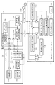
この実施の形態は、図1に示すように本発明の実施の一形態に係り、特にエアバッグ制御装置(車両用乗員保護装置)のシステム構成を示す図である。
【0011】
すなわち、10はマスターユニット、11は第1サテライトユニット(例えば運転席側加速度センサユニット)、12は第2サテライトユニット(例えば運転席用サイドエアバッグ展開駆動回路)、13は第3サテライトユニット(例えば助手席側加速度センサユニット)、14は第4サテライトユニット(例えば助手席用サイドエアバッグ展開駆動回路)、16は切替制御機能部(この切替制御機能部16は図においてはマスターユニット10と別回路ブロックで記載されているが、実際上はマスターユニット10の一部分を構成している。)で、第1乃至第4サテライトユニット11〜14及び切替制御機能部16は、一本の通信ライン15によって環状に電気接続されて電圧多重通信構成にされ、この通信ライン15(直列接続された通信ライン15a〜15eから構成されている。)によって前記マスターユニット10から第1乃至第4サテライトユニットに各種信号(データを含む)及び電力を供給している。すなわち、前記通信ライン15は信号ラインを電源ラインとを兼ねている。
なお、前記第1乃至第4サテライトユニット11〜14は、スレーブユニットを形成している。
【0012】
次に、前記マスターユニット10、切替制御機能部16、第1乃至第4サテライトユニット11〜14の順に詳細構成を説明する。
まず、前記マスターユニット10は、従来例におけるセンターユニット3と多少異なるがほぼ同等の機能、すなわち衝突判断機能部10a、診断機能部10b及び多重通信機能部10cを有するマイクロコンピュータ、電源回路10d、前後方向加速度センサ10e等によって構成されており、診断機能部10b及び多重通信機能部10cは、切替制御機能部16の第1回線切替機能部16aを介して通信ライン15aに接続され、また第2回線切替機能部16bを介して通信ライン15eに接続されている。
【0013】
次に、前記切替制御機能部16は、第1回線切替機能部16a、第2回線切替機能部16b、コマンド発行機能部16c等が設けられたマイクロコンピュータ、該マイクロコンピュータに給電する直流電源16dから構成されて、コマンド発行機能部16cは、前記マスターユニット10の衝突判断機能部10a及び診断機能部10bからの指示に基づいて第1回線切替機能部16a又は第2回線切替機能部16bを択一的に活性化し、その活性化された第1回線切替機能部16a又は第2回線切替機能部16bを介して、前記マスターユニット10からの指示に基づいて電源投入時には、前記第1回線切替機能部16a又は第2回線切替機能部16bのうち活性化されている方に対して電源回路10dからの直流出力に、第1乃至第4サテライトユニット11〜14のそれぞれにアドレス及び各種要求信号を供給するための信号を重畳せしめる。
【0014】
また、前記コマンド発行機能部16cは、第1回線切替機能部16aを活性化した後、図4に示すフローチャートにおける初期設定処理Aを実行し、正常と判断された時には、通信障害検知処理B、正常通信処理Cを進める。
【0015】
さらに、前記コマンド発行機能部16cは、前記初期設定処理Aにおいて、通信ライン15、又は前記第1乃至第4サテライトユニット11〜14の何れかに通信障害が発生していると前記マスターユニット10の診断機能部10bが判断した場合、マスターユニット10の診断機能部10bの指示に基づき第1回線切替機能部16aを不活性化すると同時に第2回線切替機能部16bを活性化し、図2に示すフローチャートに従って、初期設定処理A、通信障害検知処理B、正常通信処理C、通信異常発生部位検知D、通信異常発生部位切断及び通信再構築Eを進める。
【0016】
またさらに、前記コマンド発行機能部16cは、正常通信中に通信ライン15、又は前記第1乃至第4サテライトユニット11〜14の何れかに通信障害が発生したと判断されると、マスターユニット10の診断機能部10bの指示に基づき、例えば第1回線切替機能部16aを不活性化すると同時に第2回線切替機能部16bを活性化し、図4に示すフローチャートに従って初期設定処理A、通信障害検知処理B、正常通信処理C、通信異常発生部位検知D、通信異常発生部位切断及び通信再構築Eを進める。
また、逆に第2回線切替機能部16bを不活性化した場合には、それと同時に第1回線切替機能部16aを活性化する。
【0017】
次に、前記第1サテライトユニット11は、第1バススイッチ(第1スイッチ手段)11a、第1制御スイッチ(第2スイッチ手段)11b、第2制御スイッチ(第3制御スイッチ手段)11c、第1回線電圧監視回路11d、第2回線電圧監視回路11e、第1インターフェイス11h、コマンド解読回路(マイクロコンピュータから構成されている)11f、第1直流電源11g等から構成され、前記第1バススイッチ11aは、直列接続された通信ライン15a、15b間に介挿されている。また、前記第1制御スイッチ11b及び第2制御スイッチ11cは、直列接続されると共に、その直列接続された状態で前記第1バススイッチ11aに対して並列接続されている。
【0018】
また、前記第1回線電圧監視回路11dは、前記第1サテライトユニット11の2つの入出力端子のうちの一方の入出力端子に接続された信号ライン15aの電圧を監視し、前記マスターユニット10の電源回路10dの作動開始後の一定電圧に、前記コマンド発行部16cから出力されて、電圧多重化される最初のアドレス信号の電圧の立ち下がりを検知して前記第1制御スイッチ11bをオンする。
【0019】
前記第2回線電圧監視回路11eは、前記第1サテライトユニット11の他方の入出力端子に接続されて、前記マスターユニット10の電源回路10dの作動開始後に発生する前記通信ライン15又は前記第1乃至第4サテライトユニット11〜14の何れかに通信障害が発生したときの該第1乃至第4サテライトユニット11〜14のリセット後の信号ライン15bの電圧を監視し、前記切替制御機能部16の指示により信号ライン15bに電圧多重化される最初のアドレス信号の電圧の立ち下りを検知して前記第2制御スイッチ11cをオンする。
【0020】
第1インターフェイス11hは、前記直列接続された第1及び第2制御スイッチ11b,11cの接続点に入出力端子が接続され、前記通信ライン15からアドレス信号及び要求信号の供給を受けて、それを前記第1コマンド解読回路11fに供給すると共に、該第1コマンド解読回路11fから出力される応答信号及びエアバッグ展開要求信号を前記通信ライン15に対して出力する。
【0021】
なお、前記第1コマンド解読回路11fは、アドレス信号が供給されると、前記マスターユニット10及び切替制御機能部16に対して自分のユニットと他の第2乃至第4サテライトユニット12〜14とを区別するための固有のアドレス信号としてメモリ11iに記憶せしめ、初期設定すると共に、第1バススイッチ11aをオンせしめる。
【0022】
また、前記第1コマンド解読回路11fは、常に自己のユニットの自己診断を行っており、要求信号が供給されると、その自己診断の結果を前記第1インターフェイス11hに対して出力する一方で、その診断結果が自己回路、すなわちこの場合は、第1サテライトユニット11に通信障害が発生したものと判断される場合には前記第1バススイッチ11a、第1制御スイッチ11b及び第2制御スイッチ11cをオフせしめ、かつ前記メモリ11iに記憶したアドレスを廃棄し、さらに前記第2直流電源11gを強制的に作動不能にし、この第2直流電源11gを構成するコンデンサに蓄積されている電荷を放電し、再起動不能にし、誤動作発生の可能性を完全になくす。すなわち初期設定を行う。
【0023】
なお、前記第3サテライトユニット13も第1サテライトユニット11と同様の構成を有し、それぞれの第1バススイッチ(第1スイッチ手段)13aは、第1サテライトユニット11の第1バススイッチ11aに相当し、第1制御スイッチ(第2制御スイッチ手段)13bは、第1サテライトユニット11の第1制御スイッチ11bに相当し、第2制御スイッチ(第3スイッチ手段)13cは、第1サテライトユニット11の第2制御スイッチ11cに相当し、第1回線電圧監視回路13dは、第1サテライトユニット11の第1回線電圧監視回路11dに相当し、第2回線電圧監視回路13eは、第1サテライトユニット11の第2回線電圧監視回路11eに相当し、第1インターフェイス13fは、第1サテライトユニット11の第1インターフェイス11fに相当し、コマンド解読回路13gは、第1サテライトユニット11の第1コマンド解読回路11fに相当し、第2直流電源13hは、第1サテライトユニット11の第2直流電源11hに相当する。
【0024】
また、前記第2及び第4サテライトユニット12、14も基本的には第1サテライトユニット11と同様の構成を有し、それぞれの第1バススイッチ(第1スイッチ手段)12a、14aは、第1サテライトユニット11の第1バススイッチ11aに相当し、第1制御スイッチ(第2スイッチ制御)12b、14bのそれぞれは、第1サテライトユニット11の第1制御スイッチ11bに相当し、第2制御スイッチ(第3スイッチ手段)12c、14cのそれぞれは、第1サテライトユニット11の第2制御スイッチ11cに相当し、第1回線電圧監視回路12d、14dのそれぞれは、第1サテライトユニット11の第1回線電圧監視回路11dに相当し、第2回線電圧監視回路12e、14eのそれぞれは、第1サテライトユニット11の第2回線電圧監視回路11eに相当し、第1インターフェイス12f、14fのそれぞれは、第1サテライトユニット11の第1インターフェイス11fに相当し、コマンド解読回路12g、14gのそれぞれは、第1サテライトユニット11の第1コマンド解読回路11fに相当し、第2直流電源12h、14hのそれぞれは、第1サテライトユニット11の第2直流電源11hに相当する。
【0025】
ただし、前記第1及び第3サテライトユニット11、13と前記第2及び第4サテライトユニット12、14との違いは、前記第1及び第3サテライトユニット11、13には加速度センサ11j、13jが接続され、また前記第2及び第4サテライトユニット12、14では、加速度センサ11j、13jに替えてスクイーブ12j、14jが接続されている点にある。
【0026】
次に、上記マスターユニット10の前記切替制御機能部16に対する制御の概要は図4のフローチャートに示され、またそのフローチャート中の各ブロックの詳細フローチャートは図7乃至図8に示されている。
【0027】
先ず、マスターユニット10の通信機能の全体概要の説明を、図4に示すフローチャートに基づいて行う。
最初に、電源投入時に伴う初期設定処理ステップAを行ったのちに、次のステップBに進む。
まず、ステップBで通信障害検知処理を行い、通信障害が発生しているか否かを検知し、発生していないと判断した場合には次のステップCで通常通信処理の動作を行う。また、ステップBで通信障害が発生していると判断された場合には次のステップDで通信障害部位検知処理を行い、異常箇所を確定し、次のステップEでその通信障害発生箇所、すなわち異常箇所をこの多重通信リンクから切り外すための通信障害部位切断処理及び通信回路網の再構築処理を行い、ステップCの通常通信処理に進む。ステップCが終了すると再度ステップBに戻り、上記各ステップC,D,Eを繰り返して実行する。
【0028】
以下、これらの各ステップについて説明する。
(初期設定処理)
次に、図4のステップAでの初期設定処理における通信障害発生検知の説明を行う。
この初期設定処理のステップAに進むと、前記コマンド発行機能部16cによって第1回線切替機能部16aを活性化する一方で、第2回線切替機能部16bを不活性化し、信号ライン15aに対して第1サテライトユニット11のアドレス及び要求信号を出力し、その要求信号に対する第1サテライトユニット11からの、通信回路が正常であることを示す応答信号を確認する。この確認動作と同一の動作を第2乃至第4サテライトユニット12〜14のそれぞれについても順番に同様なアクセスを行い、通信障害があるか否かの診断を行い、次のステップBに進む。
【0029】
すなわち、前記マスターユニット10と第1〜第4サテライトユニット11〜14との通信には、図5(A)、(C)に示すように1フレーム当たりの所定時間Tが設定値として与えられるが、その1フレームは基本的にはアドレス信号の部分、要求信号の部分、応答信号の部分及び第1〜第4サテライト緊急通信エリアの部分から構成されている。
【0030】
次に、図7に示すフローチャートに基づいて具体的に述べる。
まず、電源が投入されると、ステップAにおいて、コマンド発行機能部16cは、コマンド発行機能部16cからの出力信号(アドレス信号、要求信号)を、例えば時計方向(図1に示すA方向)に伝送するために、コマンド発行機能部16cからの指示に基づいて第1回線切替機能部16aのみを活性化させ(ステップST210)、第1回線切替機能部16aが正常に活性化されると、第1サテライトユニット11から第4サテライトユニット14まで順番にアドレス信号及び要求信号を出力するが、ここでは第1〜第4サテライト11〜14まで同一内容の初期設定処理を行うので、第1サテライトユニット11を代表して以下に説明する。まず、ステップST220で出力された要求信号に対する第1サテライトユニット11からの通信回路が正常であることを示す応答信号を確認する。正常に通信可能と判断されると、マスターユニット10の診断機能部10bに対してそれを示す信号が供給され、ステップBのステップST230に進む。
【0031】
一方、正常に通信されていないことを示す信号が所定時間待っても確認されないと前記診断機能部10bが判断した場合(ステップST220、240)には、コマンド発行機能部16cからの出力信号(アドレス信号、要求信号)を、例えば反時計方向(図1に示すB方向)に伝送するために前記診断機能10bは、前記コマンド発行機能部19に対して第1回線切替機能部16aを不活性化させるように指示する(ステップST250)と共に、その替わりに第2回線切替機能部16bを活性化させるための指示を行う(ステップST260)。そして、第1回線切替機能部16aの場合と同様の診断を、図5(B)に示すような逆の順番に従って、すなわち第4サテライトユニット14、第3サテライトユニット13、第2サテライトユニット12、第1サテライトユニット11の順に第2回線切替機能部16bについても行う。
【0032】
次に、ステップST230で、コマンド発行機能部16cは、第1回線切替機能部16aに対して、第1サテライトユニット11と通信するためのアドレス信号及び要求信号を電源電圧に重畳させて通信ライン15に出力させ、ステップST270で第1サテライトユニット11の第1回線電圧監視回路11dが通信ライン15aからアドレス及び要求信号を受信した否かが判断され、アドレス信号及び要求信号を受信していることが応答信号に基づいて判断されると、ステップST280に進む。
【0033】
一方で、ステップST270において、アドレス信号及び要求信号を受信していないと判断されると、所定時間が経過するまでの間、ステップST270及びST290を繰り返して実行し、待つ。所定時間が経過しても受信されないと判断されると、ステップST300に進む。ステップST300では、前記コマンド発行機能部16cは前記診断機能部10bによって第1回線切替機能部16aを不活性化させるように指示し(ステップST300)、ステップST260に進み、替わりに第2回線切替機能部16bを活性化させるための指示を行う。
【0034】
ステップST270で第1回路電圧監視回路11dがアドレスを示す信号の最初の電圧変化を受信するとステップST280で第1制御スイッチ11bがオン状態にされ、アドレス信号及び要求信号が第1コマンド解読回路11fに供給される。
【0035】
第1コマンド解読回路11fに供給されたアドレス信号及び要求信号が正常に解読され、かつアドレス信号がメモリ11iに記憶された場合にはステップST310に進み、解読、記憶が正常に行われたことを示す応答信号が第1インターフェイス11hを介して第1コマンド解読回路11fから通信ライン15aに出力され、前記マスターユニット10の診断機能部10bに対して返送され、診断機能部10bによって応答信号があったと判断された場合にはステップST310からステップST320に進む。
【0036】
しかし、応答信号がない場合には、ステップST330で所定時間待ち、それでも来ない場合には通信障害発生を示す信号が診断機能部10bに供給され(ステップST340)、前記コマンド発行機能部16cは前記診断機能部10bによって第1回線切替機能部16aを不活性化させるように指示し(ステップST350)、第1乃至第4サテライトユニット11〜14の全てのスイッチ11a〜14a、11b〜14b、11c〜14c、11d〜14dをオフする指示を行い(ステップST380)、ステップST260に進む。
【0037】
前記ステップST310でアドレス信号がメモリ11iに記憶され、前記ステップST310からステップST320に進んだ場合には、ステップST320で第1サテライトユニット11の第1バススイッチ11aをオンせしめるための信号をコマンド発生回路16から第1回線切替機能部16aに指示することによってそれを示すアドレス信号及び要求信号が第1回線切替機能部16aから通信ライン15に出力されることが要求されるが、第1サテライトユニット11の第1コマンド監視部26がそれを認識し、第1バススイッチ11aをオンせしめ、第1バススイッチ11aがオンされたことが前記診断機能部10bによって確認された場合(ステップST390)には、図8に示すステップA’ブロックCで示される第2サテライトユニット12の初期設定処理のフローチャートに進む。
【0038】
このステップA’のフローチャートは、実質第1サテライトユニット11を対象に行ったステップAと同じことを実行する。
一方で、ステップST390で応答信号が第1インターフェイス11hを介して第1コマンド解読回路11fから通信ライン15aに出力され、前記マスターユニット10の診断機能部10bに対して返送され、診断機能部10bによって応答信号がないことが、ステップST400で所定時間待って、それでも来ない場合には通信障害発生と判断され(ステップST410)、前記コマンド発行機能部19は前記診断機能部10bによって第1回線切替機能部16aを不活性化させるように指示し(ステップST420)、次のステップST430で第1乃至第4サテライトユニット11〜14の全てのスイッチ11a〜11e、12a〜12e、13a〜13e、14a〜14eオフする指示を出力し、その後ステップST260に進む。
【0039】
その後、前述の如く、図8のステップA’に進み、第サテライトユニット12の初期設定処理を行い、それが終了すると、図8のステップA’’ブロックDに進み、第3サテライトユニット13の初期設定処理に進む場合も、また第3サテライトユニット14の初期設定処理が終了した後に第3サテライトユニット13から第4サテライトユニット14の初期設定処理のステップA’’’に進む場合も、同様なステップを順番に実行し、それらが正常に終了すると、図4のステップBの通信障害検知処理に入る。
【0040】
しかしながら、上記の如く、この第1、第2、第3、第4サテライトユニット11〜14の順に通信を行うための初期設定処理が出来なかったならば逆方向、すなわち前記第1回線切替機能部16aを不活性化すると共に前記第2回線切替機能部16bを活性化して、図5(B)の如く、第4、第3、第2、第1サテライトユニット14〜11の順に通信を行う初期設定を行い、通常通信に入るが、第1及び第4サテライトユニット11、14の双方が通信障害を発生している場合には初期設定は行われず、通信不能になる。
なお、前記通信障害検知処理は、上記の初期設定処理(図4のステップA)において行われるものを同一処理を行うことによって通信不能と判断された部位を認識することによって行われる。
【0041】
(通常通信処理)
次に、上記の初期設定処理の結果、正常に通信が行われると判断されると、次に述べる通常通信処理(図4のステップC)が、図9に基づくフローチャートに従って行われる。
これは、多重通信におけるスター接続時の通信と同一の通信方式を行うものであり、以下にその詳細を述べる。
【0042】
通常、イグニッションスイッチのオンによる電源の投入に伴って、第1回線切替機能部16aが活性化され、かつ前記第2回線切替機能部16bが不活性化された状態でマスターユニット10が作動を開始すると、ステップST500に進み、前記多重通信機能部10Cは、通信ライン15aに対して第1、第2、第3、第4サテライトユニット11〜14の順番に、図5(A),(C)に示すアドレス信号、要求信号、応答信号及び展開要求アドレス書き込みエリアを1フレームにした通信を行うが、この通信を行う対象となるサテライトユニットは今回通信ライン15aに供給されるアドレスによって指定される。
【0043】
すなわち、供給されたアドレス信号が、初期設定において、例えば第1サテライトユニット11のメモリ11iに記憶されたアドレス信号と一致するならば(ステップST510)、前記多重通信機能部10Cは、第1サテライトユニット11と通信を行い、また第2サテライトユニット12のメモリ12iに記憶されたアドレス信号と一致するならば(ステップST510)、前記多重通信機能部10Cは、第2サテライトユニット12と通信を行う。
なお、第3、第4サテライトユニット13、14についても同様である。
【0044】
次にその代表として、まず前記診断機能部10bと第1及び第2サテライトユニット11、12との間の通信を説明する。
まず、第1サテライトユニット11において、例えば、図5(A)に示す第1フレームの要求信号、すなわち図5(C)に示す要求信号が第1サテライトユニット11に供給され、第1コマンド解読回路11fがその要求信号を解読し、その要求信号に対する応答信号(図5(C)参照)を第1サテライトユニット11から通信ライン15aを介して前記多重通信機能部10Cを介して診断機能部10bに供給されると、該診断機能部10bにおいて、第1サテライトユニット11内部及びその通信ライン15aに通信障害があるか否かの診断が行われる。
【0045】
そして、この診断は同様にして第2サテライトユニット12についても行われ、前記多重通信機能部10Cから診断機能部10bに供給され、通信障害があるか否かの診断が行われる。
また、図7のステップAで示される初期設定処理において、第1回線切替機能部16aと所定時間を要しても行われなかった場合(ステップST520)には、ステップST530に進み、逆に第2回線切替機能部16bを活性化し、かつ前記第1回線切替機能部16aが不活性化させる。この状態でマスターユニット10が作動を開始した場合においては、第4、第3、第2、第1サテライトユニット14〜11の順に通信が行われるようになる(ステップST540)。
【0046】
(上記通常通信における衝突発生時の通信)
次に、第2サテライトユニット12との通信の説明に進む。
例えば前記(通常通信処理)における前記診断機能部10bと第1サテライトユニット11との間で通信が行われていた時に、例えば、図5(A)の時刻Xにおいて第3サテライトユニット13が車両横(左右)方向から衝突が発生したことを検知した場合を例にとって以下に説明する。
【0047】
すなわち、前記診断機能部10bと第1サテライトユニット11との間で要求信号及び応答信号の通信が行われている間の時刻内の時刻Xにおいて、例えば第3サテライトユニット13が車両横方向から衝突を、横方向加速度センサ13jによって検出すると、前記第3サテライトユニット13の第3コマンド解読回路13fは、前記図3に示すように指定された特定の第3サテライト緊急通信エリアの中に横方向からの衝突が発生した旨を知らせる衝突データを書き込む(図5(D)の斜線部分)。
【0048】
その特定エリアに書き込まれた衝突データを、マスターユニット10の衝突判断機能部10aが受信すると、前記衝突判断機能部10aは、その後、前記第2サテライトユニット12とのY−Y’区間の通信は行わずに、飛び越して、衝突発生を示すデータを送信してきた第3サテライトユニット13との多重通信を開始するために、前記3サテライトユニット13に対して図5の最初の区間T’に示すアドレス信号及び要求信号を通信ライン15c〜15aを介して供給する。
【0049】
その結果、前記第3サテライトユニット13のコマンド解読機能部13fは、衝突発生を示す応答信号を通信ライン15c〜15a、第1回線切替機能部16aを介して前記衝突判断機能部10aに供給し、この衝突判断機能部10aは、前記第3サテライトユニット13が衝突を検知したことを他の展開条件に照らし合わせた結果として、衝突と判断した場合には、この第3サテライトユニット13と対にされて設けられているサイドエアバッグ展開用の第4サテライトユニット14に対して、第4サテライトユニット14のアドレスを添付してスクイーブ点火を指示する要求信号(図5(D)の左から第2番目の区間T’に示すアドレス信号及び要求信号に相当する)を信号ライン15a〜15dを介して供給すると、第4サテライトユニット14は図示されないスクイーブに点火信号を供給し、エアバッグ等を展開させた後に、展開終了データを応答信号として前記多重通信機能部10Cに返送する。
【0050】
それによって、前記第4サテライトユニット14の第4コマンド解読回路14fは、前記スクイーブ点火を指示する要求信号を通信ライン15a〜15dを介して読み取り、その要求を解読すると、スクイーブに点火電流を供給してサイドエアバッグを展開させる。
【0051】
なお、前記(通常通信処理)において、前記マスターユニット10の多重通信機能部10Cと第1〜第4サテライトユニット11〜14との通信中に通信障害が発生したと判断したときには、図4に示すフローチャートの(ステップDの至通信障害検出処理、ステップEの通信障害部位切断処理及び再構築処理)に進む。
【0052】
(通信障害検出処理、通信障害部位切断処理及び再構築処理)
これらの機能は、第1サテライトユニット11、第2サテライトユニット12、第3サテライトユニット13、第4サテライトユニット14のそれぞれに対して順番に行うもので、実質行う内容は同じであるので、第1サテライトユニット11についてのみ代表して以下に行う。なお、この処理は、図4のステップD,Eについてのものである。
【0053】
まず、全体のフローチャートの説明を行い、次にその具体例の説明を行う。
図9において、ステップST500で、コマンド発行機能部16cは、第1回線切替機能部16aに対して第1サテライトユニット11のアドレス信号及び要求信号を通信ライン15に出力させ、その要求信号に対する応答信号が所定時間の間に返送されてくるか否かを判断する(ステップST510、520)。ステップST520において、所定時間が経過したと判断されると、ステップST530で、前記診断機能部10bは、第1サテライトユニット11との間に通信障害が発生していると判断して、前記コマンド発行機能部16cに対して前記診断機能部10bは、第1バススイッチ11aがオフ状態にする指示信号を出力し、該第1バススイッチ11aがオフされ、続くステップST540で第1サテライトユニット11をリセットせしめることによって他の制御スイッチ11b、11cをオフし、図4のステップEの通信障害発生部位切断及び再構築処理に進む。
【0054】
なお、応答信号を診断機能部10bが受信したと判断した場合には、次のブロックに進み、第2サテライトユニット12についても上記と同様の信号処理を行い、更に第3サテライトユニット13、第4サテライトユニット14へと進む。
【0055】
次に、具体例の説明を図6(e)に基づいて行う。
すなわち、前記診断機能部10bが第1サテライトユニット11との間で正常な通常通信を行い(図6(a)の部分)、次に第2サテライトユニット12に対して第2サテライトユニット12のアドレス信号及び要求信号を出力し、それに対する応答信号を受信できず(図6(b)の斜線部分の区間)、マスターユニット10の診断機能部10bによって第2サテライトユニット12において通信障害が発生していると判断された場合には、第2サテライトユニット12に対して要求信号として第2バススイッチ12a、第3制御スイッチ12b及び第3制御スイッチ12cをオフするための信号を供給し(図6(c)のT’の区間)、第2バススイッチ12a、第3制御スイッチ12b及び第3制御スイッチ12cをオフする。
【0056】
その後、コマンド発行機能部16cは、前記第1回線切替機能部16aを不活性化すると共に、前記第2回線切替機能部16aを活性化し、上記の初期設定処理を行った後(図6(d)のSの区間)、通常通信処理を行う(図6(e)のUの区間)。
すなわち、第2サテライトユニット12を除いた他の第1サテライトユニット11、第3サテライトユニット13及び第4サテライトユニット14との間で通信を開始するために、前記切替制御機能部16が、今まで活性化されていなかった、第2回線切替機能部16bを第1回線切替機能部16aに替えて活性化し、第4サテライトユニット14、第3サテライトユニット13、第2サテライトユニット12、第1サテライトユニット11の順番に上記の如き初期設定処理を行うが、その前に第1〜第4サテライトユニット11〜14の全てをリセットし、メモリ11i〜14iに記憶されていたアドレス信号を廃棄し、さらに第1〜第4バススイッチ20、第1〜第8制御スイッチ21〜28を全てオフする要求信号を出力することによって、回路システム全体が再構築され、第1、第3及び第4サテライトユニット11,12,14に対して図4に示すフローチャートに従って処理を行い、再構築する。
【0057】
【発明の効果】
以上説明したように第1の発明によれば、スレーブユニットはいつでも必要に応じてマスタユニットに対して情報を伝送出来るようになるので、情報伝送に時間遅れが無く、タイムリーになる送信できるという効果を奏する。
また、そのためにスレーブユニットの接続数を多くしても割込が効くので、スレーブユニットからの情報伝送に何等障害が発生しないという効果が発揮される。
【0058】
また、第2の発明によれば、スレーブユニットが、衝突を検出したときには、いつでも必要に応じてマスタユニットに対して衝突情報を時間遅れが無く、タイムリーになる送信できるという効果を奏する。
また、スレーブユニットの接続数が多くなっても衝突発生時には、割込が効くので、衝突情報の伝送をタイムリーに行えるという効果が発揮される。
【図面の簡単な説明】
【図1】この発明に係る一実施の形態を示す、多重通信回路を用いた車両用乗員保護装置の回路ブロック説明図である。
【図2】この発明に係る一実施の形態を示す、多重通信回路を用いた車両用乗員保護装置の回路ブロック説明図である。
【図3】この発明に係る一実施の形態を示す、多重通信回路を用いた車両用乗員保護装置の回路ブロック説明図である。
【図4】図1〜図3に示す装置の大略作動説明のためのフローチャートである。
【図5】図1〜図3の作動を説明するためのタイムチャートである。
【図6】図1〜図3の作動を説明するためのタイムチャートである。
【図7】図1〜図3に示す装置の初期設定時のフローチャートである。
【図8】図1〜図3に示す装置の初期設定時のフローチャートである。
【図9】図1〜図3に示す装置の通常時のフローチャートである。
【図10】従来のエアバッグユニットの全体概略説明図である。
【符号の説明】
10 マスタユニット
10a 衝突判断機能
10b 診断機能部
10c 多重通信機能部
11〜14 サテライトユニット
11a、12a、13a、14a バススイッチ
11b、11c、12b、12c、13b、13c、14b、14c 制御スイッチ
11d、11e、12d、12e、13d、13e、14d、14e 回線電圧監視回路
11f、12f、13f、14f コマンド解読回路
11g、12g、13g、14g 直流電源
11h、12h、13h、14h インターフェイス
11i、12i、13i、14i メモリ
10d 電源回路
11j、13j 加速度センサ
12j、14j スクイーブ
15、15a〜15d 通信ライン
16 切替制御機能部
16a、16b 回線切替機能部
16c コマンド発行機能部
16d 直流電源[0001]
BACKGROUND OF THE INVENTION
The present invention relates to an occupant protection device using a multiplex communication equipment.
[0002]
[Prior art]
Conventionally, this type is as shown in FIG. 10 and will be described below.
That is, the
[0003]
Further, the plurality of
As a prior art of this type, for example, there is one disclosed in Japanese Patent Laid-Open No. 10-154992.
[0004]
[Problems to be solved by the invention]
However, in the case of such a configuration, if any satellite unit detects a collision, the master unit must wait until a request signal is transmitted from the master unit to the detected satellite unit. Therefore, there was a problem that it was not possible to convey that the collision was detected as a response signal.
For this reason, when the number of satellite units increases, it takes a lot of time to go around each satellite unit. Therefore, when a satellite unit detects a collision, it takes a maximum time to complete one round. Otherwise, there is a possibility that the master unit cannot be notified of the collision detected as a response signal.
[0005]
The present invention has been made to solve the above-described problems, and an object of the present invention is to enable immediate transmission without delay when transmitting urgent data from a satellite unit to a master unit.
[0006]
[Means for Solving the Problems]
In the occupant protection device according to the present invention, a master unit that determines the magnitude of a collision from the front and a plurality of slave units that determine the magnitude of a collision from a side surface are connected in a ring shape, and the master unit is the plurality of slaves. for each unit, transmits a request signal via the communication line, have line communication by receiving a response signal from each slave unit to it, igniting drives Sukuibu optionally said master unit In the occupant protection device,
In the response signals output from the plurality of slave units, data indicating the occurrence of a collision is written in the writing area when any of the slave units determines a collision, and the master unit has the collision written in the writing area. When the data is received, the occupant protection device, wherein an address signal and a request signal shown in the first section are supplied to the slave unit that has transmitted the occurrence of a collision.
[0009]
The write area can be reliably written by being set for each of the plurality of slave units.
[0010]
DETAILED DESCRIPTION OF THE INVENTION
This embodiment relates to an embodiment of the present invention as shown in FIG. 1, and is a diagram showing a system configuration of an airbag control device (vehicle occupant protection device).
[0011]
That is, 10 is a master unit, 11 is a first satellite unit (for example, a driver's seat side acceleration sensor unit), 12 is a second satellite unit (for example, a driver side airbag deployment drive circuit), and 13 is a third satellite unit (for example, (Passenger seat side acceleration sensor unit), 14 is a fourth satellite unit (for example, side airbag deployment drive circuit for passenger seat), 16 is a switching control function section (this switching
The first to
[0012]
Next, the detailed configuration will be described in the order of the
First, the
[0013]
Next, the switching
[0014]
Further, after activating the first line
[0015]
Further, the command issuing
[0016]
Furthermore, when it is determined that a communication failure has occurred in the
Conversely, when the second line
[0017]
Next, the
[0018]
The first line
[0019]
The second line
[0020]
The first interface 11h has an input / output terminal connected to a connection point of the first and second control switches 11b and 11c connected in series, receives an address signal and a request signal from the
[0021]
When the address signal is supplied, the first command decoding circuit 11f sends its own unit and the other second to
[0022]
The first command decoding circuit 11f always performs self-diagnosis of its unit, and when a request signal is supplied, outputs the result of the self-diagnosis to the first interface 11h. If the diagnosis result is a self-circuit, that is, in this case, it is determined that a communication failure has occurred in the
[0023]
The
[0024]
The second and
[0025]
However, the difference between the first and
[0026]
Next, an outline of control of the
[0027]
First, an overview of the communication function of the
First, after performing the initial setting process step A when the power is turned on, the process proceeds to the next step B.
First, in step B, communication failure detection processing is performed to detect whether a communication failure has occurred. If it is determined that no communication failure has occurred, normal communication processing is performed in next step C. If it is determined in step B that a communication failure has occurred, a communication failure part detection process is performed in the next step D, an abnormal part is determined, and in step E, the communication failure part, that is, A communication failure site disconnection process and a communication network reconfiguration process for disconnecting the abnormal part from the multiplex communication link are performed, and the process proceeds to the normal communication process of Step C. When step C ends, the process returns to step B again, and the above steps C, D, and E are repeatedly executed.
[0028]
Hereinafter, each of these steps will be described.
(Initial setting process)
Next, detection of communication failure occurrence in the initial setting process in step A of FIG. 4 will be described.
When the process proceeds to step A of the initial setting process, the first line switching
[0029]
That is, for communication between the
[0030]
Next, a specific description will be given based on the flowchart shown in FIG.
First, when the power is turned on, in step A, the command issuing
[0031]
On the other hand, when the
[0032]
Next, in step ST230, the command issuing
[0033]
On the other hand, if it is determined in step ST270 that the address signal and the request signal have not been received, steps ST270 and ST290 are repeatedly executed and waited until a predetermined time elapses. If it is determined that it has not been received even after the predetermined time has elapsed, the process proceeds to step ST300. In step ST300, the command issuing
[0034]
When the first circuit
[0035]
If the address signal and the request signal supplied to the first command decoding circuit 11f are normally decoded and the address signal is stored in the memory 11i, the process proceeds to step ST310 to confirm that the decoding and storage are normally performed. The response signal shown is output from the first command decoding circuit 11f to the
[0036]
However, if there is no response signal, it waits for a predetermined time in step ST330. If it still does not come, a signal indicating the occurrence of communication failure is supplied to the
[0037]
If the address signal is stored in the memory 11i in step ST310 and the process proceeds from step ST310 to step ST320, a signal for turning on the
[0038]
The flowchart of step A ′ performs the same operation as step A performed for the
On the other hand, in step ST390, a response signal is output from the first command decoding circuit 11f to the
[0039]
Thereafter, as described above, the process proceeds to step A ′ in FIG. 8 to perform the initial setting process of the
[0040]
However, as described above, if the initial setting process for performing communication in the order of the first, second, third, and
The communication failure detection process is performed by recognizing a part that is determined to be unable to communicate by performing the same process as that performed in the initial setting process (step A in FIG. 4).
[0041]
(Normal communication processing)
Next, when it is determined that the communication is normally performed as a result of the initial setting process, the normal communication process (step C in FIG. 4) described below is performed according to the flowchart based on FIG.
This is the same communication method as the communication at the time of star connection in multiplex communication, and the details will be described below.
[0042]
Normally, the
[0043]
That is, if the supplied address signal matches the address signal stored in the memory 11i of the
The same applies to the third and
[0044]
Next, as a representative example, communication between the
First, in the
[0045]
This diagnosis is also performed on the
In addition, in the initial setting process shown in step A of FIG. 7, when the predetermined time has not been taken with the first line switching
[0046]
(Communication at the time of collision in the above normal communication)
Next, the description proceeds to the communication with the
For example, when communication is being performed between the
[0047]
That is, for example, the
[0048]
When the collision
[0049]
As a result, the command decoding function unit 13f of the
[0050]
As a result, the fourth command decoding circuit 14f of the
[0051]
When it is determined in the above (normal communication processing) that a communication failure has occurred during communication between the multiplex communication function unit 10C of the
[0052]
(Communication failure detection processing, communication failure site disconnection processing, and reconstruction processing)
These functions are performed in order for each of the
[0053]
First, the entire flowchart will be described, and then a specific example thereof will be described.
In FIG. 9, in step ST500, the command issuing
[0054]
If it is determined that the
[0055]
Next, a specific example will be described with reference to FIG.
That is, the
[0056]
Thereafter, the command issuing
That is, in order to start communication with the other
[0057]
【The invention's effect】
As described above, according to the first invention, the slave unit can transmit information to the master unit at any time as needed, so that there is no time delay in information transmission and timely transmission can be performed. There is an effect.
For this reason, even if the number of slave units connected is increased, the interruption is effective, so that an effect that no trouble occurs in information transmission from the slave unit is exhibited.
[0058]
In addition, according to the second invention, when the slave unit detects a collision, there is an effect that the collision information can be transmitted to the master unit in a timely manner without any time delay as necessary.
Also, even if the number of slave units connected increases, an interrupt is effective when a collision occurs, so that the effect of being able to transmit collision information in a timely manner is exhibited.
[Brief description of the drawings]
FIG. 1 is a circuit block diagram of a vehicle occupant protection device using a multiplex communication circuit, showing an embodiment according to the present invention.
FIG. 2 is a circuit block explanatory diagram of a vehicle occupant protection device using a multiplex communication circuit, showing an embodiment according to the present invention.
FIG. 3 is a circuit block diagram of a vehicle occupant protection device using a multiplex communication circuit according to an embodiment of the present invention.
FIG. 4 is a flowchart for explaining the general operation of the apparatus shown in FIGS.
FIG. 5 is a time chart for explaining the operation of FIGS. 1 to 3;
6 is a time chart for explaining the operation of FIGS. 1 to 3; FIG.
FIG. 7 is a flowchart at the time of initial setting of the apparatus shown in FIGS.
FIG. 8 is a flowchart at the time of initial setting of the apparatus shown in FIGS.
FIG. 9 is a flowchart in a normal state of the apparatus shown in FIGS.
FIG. 10 is an overall schematic explanatory view of a conventional airbag unit.
[Explanation of symbols]
DESCRIPTION OF
Claims (2)
前記複数のスレーブユニットから出力される応答信号に、該スレーブユニットの何れかが衝突を判断したときの、書き込みエリアに衝突発生を示すデータを書込み、前記マスタユニットは前記書き込みエリアに書き込まれた衝突データを受信すると、衝突発生を送信してきた前記スレーブユニットに対して最初の区間に示すアドレス信号及び要求信号を供給することを特徴とする乗員保護装置。 A master unit for determining the magnitude of collision from the front and a plurality of slave units for determining the magnitude of collision from the side are connected in a ring shape, and the master unit is connected to each of the plurality of slave units with the communication line. in the passenger protection apparatus transmits, have rows communication by receiving a response signal from each slave unit to it, igniting drives Sukuibu optionally said master unit a request signal via,
In the response signals output from the plurality of slave units, data indicating the occurrence of a collision is written in the writing area when any of the slave units determines a collision, and the master unit has the collision written in the writing area. When the data is received, the occupant protection device, wherein an address signal and a request signal shown in the first section are supplied to the slave unit that has transmitted the occurrence of a collision.
Priority Applications (5)
| Application Number | Priority Date | Filing Date | Title |
|---|---|---|---|
| JP2002052026A JP4037129B2 (en) | 2002-02-27 | 2002-02-27 | Multiple communication device and occupant protection device using the same |
| KR10-2003-0012073A KR20030071532A (en) | 2002-02-27 | 2003-02-26 | Multiplex communication system and car-passenger protection system using the same |
| US10/373,200 US7546192B2 (en) | 2002-02-27 | 2003-02-26 | Multiplex communication system and car-passenger protection system using the same |
| DE60300557T DE60300557T2 (en) | 2002-02-27 | 2003-02-27 | Multiplex communication system and car occupant protection system based thereon |
| EP03004317A EP1349326B1 (en) | 2002-02-27 | 2003-02-27 | Multiplex communication system and car-passenger protection system using the same |
Applications Claiming Priority (1)
| Application Number | Priority Date | Filing Date | Title |
|---|---|---|---|
| JP2002052026A JP4037129B2 (en) | 2002-02-27 | 2002-02-27 | Multiple communication device and occupant protection device using the same |
Publications (2)
| Publication Number | Publication Date |
|---|---|
| JP2003258821A JP2003258821A (en) | 2003-09-12 |
| JP4037129B2 true JP4037129B2 (en) | 2008-01-23 |
Family
ID=27800020
Family Applications (1)
| Application Number | Title | Priority Date | Filing Date |
|---|---|---|---|
| JP2002052026A Expired - Fee Related JP4037129B2 (en) | 2002-02-27 | 2002-02-27 | Multiple communication device and occupant protection device using the same |
Country Status (5)
| Country | Link |
|---|---|
| US (1) | US7546192B2 (en) |
| EP (1) | EP1349326B1 (en) |
| JP (1) | JP4037129B2 (en) |
| KR (1) | KR20030071532A (en) |
| DE (1) | DE60300557T2 (en) |
Families Citing this family (10)
| Publication number | Priority date | Publication date | Assignee | Title |
|---|---|---|---|---|
| JP4305312B2 (en) * | 2004-07-20 | 2009-07-29 | 株式会社デンソー | Obstacle detection device |
| JP2006256371A (en) * | 2005-03-15 | 2006-09-28 | Toyota Motor Corp | Starter of occupant crash protection device |
| DE102006039709A1 (en) * | 2006-08-24 | 2008-02-28 | Robert Bosch Gmbh | Method for transmitting a drive decision for an actuator from a first to at least one second control device, first control device for a vehicle, second control device for a vehicle, device for transmitting a drive decision for an actuator from a first to a second control device |
| JP5045159B2 (en) * | 2007-03-12 | 2012-10-10 | 三菱電機株式会社 | Control subunit and control main unit |
| EP1977687A1 (en) | 2007-04-05 | 2008-10-08 | Koninklijke Philips Electronics N.V. | Hydrogel based device for detecting an environmental state |
| JP5075724B2 (en) * | 2008-04-18 | 2012-11-21 | 株式会社ケーヒン | Occupant protection control device and occupant protection system |
| JP2010213168A (en) | 2009-03-12 | 2010-09-24 | Denso Corp | Communication apparatus |
| JP6640512B2 (en) * | 2015-09-29 | 2020-02-05 | エア・ウォーター防災株式会社 | Fire extinguisher |
| DE102016226136A1 (en) | 2016-12-23 | 2018-06-28 | Robert Bosch Gmbh | Method for operating a sensor device, sensor device |
| DE102018114225A1 (en) * | 2018-06-14 | 2019-12-19 | Valeo Schalter Und Sensoren Gmbh | Method for operating a sensor arrangement in a motor vehicle based on a DSI protocol |
Family Cites Families (22)
| Publication number | Priority date | Publication date | Assignee | Title |
|---|---|---|---|---|
| JPH0831869B2 (en) | 1987-02-23 | 1996-03-27 | 株式会社日立製作所 | Data transmission method and data transmission device |
| DE3816587A1 (en) * | 1988-05-16 | 1989-11-23 | Messerschmitt Boelkow Blohm | DEVICE FOR TRIGGERING A PASSIVE SAFETY DEVICE |
| JP2904283B2 (en) * | 1989-05-22 | 1999-06-14 | マツダ株式会社 | Multiplex transmission equipment for vehicles |
| JPH0769376B2 (en) | 1989-08-30 | 1995-07-31 | マツダ株式会社 | Multiplex device for vehicle |
| US5305316A (en) | 1990-09-04 | 1994-04-19 | Nissan Motor Co., Ltd. | Multiplex communication system |
| US6733036B2 (en) * | 1995-06-07 | 2004-05-11 | Automotive Technologies International, Inc. | Automotive electronic safety network |
| US6532408B1 (en) * | 1997-05-29 | 2003-03-11 | Automotive Technologies International, Inc. | Smart airbag system |
| US5468013A (en) * | 1993-12-03 | 1995-11-21 | Trw Inc. | Dual air bag system for occupant restraint |
| JPH08246512A (en) * | 1995-03-07 | 1996-09-24 | Shinwa Musen Syst Kk | Water leak detector |
| EP0802655A3 (en) | 1996-04-17 | 1999-11-24 | Matsushita Electric Industrial Co., Ltd. | Communication network |
| US5760489A (en) | 1996-10-04 | 1998-06-02 | Motorola, Inc. | Method for transmitting signals between a microprocessor and an interface circuit |
| US5964816A (en) * | 1998-01-26 | 1999-10-12 | Delco Electronics Corp. | Address communication method for a distributed architecture supplemental inflatable restraint system |
| DE19813957C2 (en) * | 1998-03-28 | 2003-06-18 | Conti Temic Microelectronic | Occupant protection system with a central unit, sensors and several control modules communicatively connected by means of a BUS system for triggering occupant protection devices |
| US6166653A (en) * | 1998-08-13 | 2000-12-26 | Motorola Inc | System for address initialization of generic nodes in a distributed command and control system and method therefor |
| JP3640143B2 (en) * | 1998-12-25 | 2005-04-20 | 日産自動車株式会社 | Crew protection device |
| GB9916359D0 (en) | 1999-07-14 | 1999-09-15 | New Holland Uk Ltd | A contoller area network |
| JP4465767B2 (en) * | 1999-12-28 | 2010-05-19 | マツダ株式会社 | Deployment control device for airbag device |
| DE10084602B4 (en) * | 2000-03-17 | 2004-02-26 | Mitsubishi Denki K.K. | Collision detection procedure and passive safety device |
| US6744820B1 (en) * | 2000-03-21 | 2004-06-01 | Trw Inc. | Communication system and method utilizing message frames having multiple thresholds for a multi-device vehicle occupant protection system |
| US6536798B1 (en) * | 2000-09-27 | 2003-03-25 | Aùtoliv ASP, Inc. | Controlling activation of restraint devices in a vehicle |
| US6922547B2 (en) * | 2001-06-27 | 2005-07-26 | Flarion Technologies, Inc. | Methods and apparatus for supporting group communications |
| US7082485B2 (en) * | 2002-07-24 | 2006-07-25 | The Boeing Company | Systems and methods for establishing peer-to-peer communications between network devices communicating via a common bus |
-
2002
- 2002-02-27 JP JP2002052026A patent/JP4037129B2/en not_active Expired - Fee Related
-
2003
- 2003-02-26 KR KR10-2003-0012073A patent/KR20030071532A/en active IP Right Grant
- 2003-02-26 US US10/373,200 patent/US7546192B2/en not_active Expired - Fee Related
- 2003-02-27 DE DE60300557T patent/DE60300557T2/en not_active Expired - Fee Related
- 2003-02-27 EP EP03004317A patent/EP1349326B1/en not_active Expired - Lifetime
Also Published As
| Publication number | Publication date |
|---|---|
| JP2003258821A (en) | 2003-09-12 |
| DE60300557T2 (en) | 2005-09-29 |
| US20040024832A1 (en) | 2004-02-05 |
| US7546192B2 (en) | 2009-06-09 |
| EP1349326B1 (en) | 2005-04-27 |
| DE60300557D1 (en) | 2005-06-02 |
| EP1349326A1 (en) | 2003-10-01 |
| KR20030071532A (en) | 2003-09-03 |
Similar Documents
| Publication | Publication Date | Title |
|---|---|---|
| JP4656421B2 (en) | Bus communication system | |
| JP4037129B2 (en) | Multiple communication device and occupant protection device using the same | |
| JP2001512396A (en) | Vehicle safety device with safety device controller | |
| JP3438217B2 (en) | Method and apparatus for controlling data transmission between two modules provided in a motor vehicle | |
| US6293583B1 (en) | Apparatus for activating passive safety device | |
| JP4037115B2 (en) | Multiple communication device and vehicle occupant protection device using the same | |
| JPH11321544A (en) | Ignition control system for vehicle occupant protective device | |
| EP2110284B1 (en) | Passenger protection control device and passenger protection system | |
| JP2006304069A (en) | Communication equipment | |
| JP3719371B2 (en) | Vehicle occupant protection system | |
| JP2001322527A (en) | Vehicular occupant protective system | |
| JPH08115235A (en) | Abnormality detector for controller and method therefor | |
| JP3623310B2 (en) | Multiplex communication equipment | |
| JPH1117716A (en) | Data communication circuit | |
| JPH1041927A (en) | Multiplex communication method and its equipment | |
| JP3868536B2 (en) | Crew protection device | |
| JPH09295551A (en) | Multiplex communication apparatus | |
| JP2001001859A (en) | Occupant crash protection system | |
| JPH09269247A (en) | Multiplex communication circuit | |
| US7110483B1 (en) | Communication method | |
| KR19990036462A (en) | Automotive Multi-Communication Circuit | |
| JP2003054357A (en) | Data communication circuit | |
| JP4065098B2 (en) | Multiple communication circuit and occupant protection device using the same | |
| JP3088200B2 (en) | Multiplex communication device | |
| JP2020143654A (en) | Vehicular control device |
Legal Events
| Date | Code | Title | Description |
|---|---|---|---|
| A621 | Written request for application examination |
Free format text: JAPANESE INTERMEDIATE CODE: A621 Effective date: 20041116 |
|
| A977 | Report on retrieval |
Free format text: JAPANESE INTERMEDIATE CODE: A971007 Effective date: 20070227 |
|
| A131 | Notification of reasons for refusal |
Free format text: JAPANESE INTERMEDIATE CODE: A131 Effective date: 20070306 |
|
| A521 | Written amendment |
Free format text: JAPANESE INTERMEDIATE CODE: A523 Effective date: 20070425 |
|
| A521 | Written amendment |
Free format text: JAPANESE INTERMEDIATE CODE: A821 Effective date: 20070920 |
|
| RD02 | Notification of acceptance of power of attorney |
Free format text: JAPANESE INTERMEDIATE CODE: A7422 Effective date: 20070920 |
|
| RD04 | Notification of resignation of power of attorney |
Free format text: JAPANESE INTERMEDIATE CODE: A7424 Effective date: 20070920 |
|
| TRDD | Decision of grant or rejection written | ||
| A01 | Written decision to grant a patent or to grant a registration (utility model) |
Free format text: JAPANESE INTERMEDIATE CODE: A01 Effective date: 20071002 |
|
| A61 | First payment of annual fees (during grant procedure) |
Free format text: JAPANESE INTERMEDIATE CODE: A61 Effective date: 20071031 |
|
| R150 | Certificate of patent or registration of utility model |
Free format text: JAPANESE INTERMEDIATE CODE: R150 |
|
| FPAY | Renewal fee payment (event date is renewal date of database) |
Free format text: PAYMENT UNTIL: 20101109 Year of fee payment: 3 |
|
| S531 | Written request for registration of change of domicile |
Free format text: JAPANESE INTERMEDIATE CODE: R313531 |
|
| FPAY | Renewal fee payment (event date is renewal date of database) |
Free format text: PAYMENT UNTIL: 20101109 Year of fee payment: 3 |
|
| R350 | Written notification of registration of transfer |
Free format text: JAPANESE INTERMEDIATE CODE: R350 |
|
| LAPS | Cancellation because of no payment of annual fees |