EP1349326A1 - Multiplex communication system and car-passenger protection system using the same - Google Patents
Multiplex communication system and car-passenger protection system using the same Download PDFInfo
- Publication number
- EP1349326A1 EP1349326A1 EP03004317A EP03004317A EP1349326A1 EP 1349326 A1 EP1349326 A1 EP 1349326A1 EP 03004317 A EP03004317 A EP 03004317A EP 03004317 A EP03004317 A EP 03004317A EP 1349326 A1 EP1349326 A1 EP 1349326A1
- Authority
- EP
- European Patent Office
- Prior art keywords
- communication
- section
- satellite
- unit
- signal
- Prior art date
- Legal status (The legal status is an assumption and is not a legal conclusion. Google has not performed a legal analysis and makes no representation as to the accuracy of the status listed.)
- Granted
Links
Images


Classifications
-
- B—PERFORMING OPERATIONS; TRANSPORTING
- B60—VEHICLES IN GENERAL
- B60R—VEHICLES, VEHICLE FITTINGS, OR VEHICLE PARTS, NOT OTHERWISE PROVIDED FOR
- B60R21/00—Arrangements or fittings on vehicles for protecting or preventing injuries to occupants or pedestrians in case of accidents or other traffic risks
- B60R21/01—Electrical circuits for triggering passive safety arrangements, e.g. airbags, safety belt tighteners, in case of vehicle accidents or impending vehicle accidents
- B60R21/013—Electrical circuits for triggering passive safety arrangements, e.g. airbags, safety belt tighteners, in case of vehicle accidents or impending vehicle accidents including means for detecting collisions, impending collisions or roll-over
- B60R21/0132—Electrical circuits for triggering passive safety arrangements, e.g. airbags, safety belt tighteners, in case of vehicle accidents or impending vehicle accidents including means for detecting collisions, impending collisions or roll-over responsive to vehicle motion parameters, e.g. to vehicle longitudinal or transversal deceleration or speed value
-
- H—ELECTRICITY
- H04—ELECTRIC COMMUNICATION TECHNIQUE
- H04L—TRANSMISSION OF DIGITAL INFORMATION, e.g. TELEGRAPHIC COMMUNICATION
- H04L12/00—Data switching networks
- H04L12/28—Data switching networks characterised by path configuration, e.g. LAN [Local Area Networks] or WAN [Wide Area Networks]
- H04L12/42—Loop networks
- H04L12/423—Loop networks with centralised control, e.g. polling
-
- B—PERFORMING OPERATIONS; TRANSPORTING
- B60—VEHICLES IN GENERAL
- B60R—VEHICLES, VEHICLE FITTINGS, OR VEHICLE PARTS, NOT OTHERWISE PROVIDED FOR
- B60R21/00—Arrangements or fittings on vehicles for protecting or preventing injuries to occupants or pedestrians in case of accidents or other traffic risks
- B60R21/01—Electrical circuits for triggering passive safety arrangements, e.g. airbags, safety belt tighteners, in case of vehicle accidents or impending vehicle accidents
- B60R2021/0104—Communication circuits for data transmission
- B60R2021/01047—Architecture
- B60R2021/01054—Bus
-
- B—PERFORMING OPERATIONS; TRANSPORTING
- B60—VEHICLES IN GENERAL
- B60R—VEHICLES, VEHICLE FITTINGS, OR VEHICLE PARTS, NOT OTHERWISE PROVIDED FOR
- B60R21/00—Arrangements or fittings on vehicles for protecting or preventing injuries to occupants or pedestrians in case of accidents or other traffic risks
- B60R21/01—Electrical circuits for triggering passive safety arrangements, e.g. airbags, safety belt tighteners, in case of vehicle accidents or impending vehicle accidents
- B60R2021/01122—Prevention of malfunction
- B60R2021/01129—Problems or faults
- B60R2021/01163—Insufficient current or voltage
Definitions
- a master unit 100 includes a microcomputer 101 and an acceleration sensor.
- the master unit 100 is coupled to a plurality of satellite units 103A, 103B, across, and 103N via a reference bus 102, and coupled to the plurality of satellite units 103A, 103B, Vietnamese, and 103N via a signal transmission bus 104.
- Squibs 105A, 105B, Vietnamese, and 105N are coupled to the satellite units 103A, 103B,...., and 103N, respectively.
- the satellite units 103A to 103N are located on the side portion of a car such as a door panel apart from the master unit 100 positioned at he center of the car. Signals are respectively supplied to the satellite units 103A to 103N through the signal transmission bus 104 from the master units 100. Electric energy is supplied to each of the satellite units 103A to 103N by voltage multiplexing. A part of the electric energy transmitted to each of the satellite units 103A to 103N is used for allowing the satellite unit 103A to 103N to operate. Other parts are stored in the satellite unit 103A, and the electric energy stored in the satellite unit 103A is supplied to the squib 105A as ignition current when an airbag needs to be developed at the time of an accident. There is a technology disclosed in Japanese Patent Laid-Open No. 10(1998)-154992 as such kinds of prior arts.
- the present invention was made to solve the above described problems, and an object of the present invention is to make it possible to transmit data, which must be transmitted immediately from a satellite unit to a master unit, immediately without delay when the data is transmitted.
- a multiplex communication system comprises a master unit and a plurality of slave units.
- the master unit and the plurality of slave units are coupled to each other by a signal line annularly.
- the master unit transmits a request signal to each of the slave units through the signal line, and receives a response signal in response to the request signal from each of the slave units.
- the response signal has a data area to which each of the slave units can write data.
- a car-passenger protection system comprises a master unit for judging a scale of collision from a first direction; a plurality of slave units include first and second slave units, the first slave unit judging a scale of collision from a second direction and the second slave unit judging a scale of collision from a third direction: and a squib operated by a control of the master unit, wherein the master unit and the plurality of slave unit are connected by a signal line annularly, and the master unit transmits a request signal to each of the slave units via the signal line and receives a response signal in response to the request signal from each of the slave units, and wherein the response signal has a data area to which each slave unit can write data, and data which indicate an occurrence of the collision is written to the data area when each slave unit detects the collision.
- FIG. 2 is a drawing illustrating a system configuration of an airbag control device (a car-passenger protection device).
- a first satellite unit 11 is a driver's seat-side acceleration sensor unit
- a second satellite unit 12 is a driver's seat-side airbag developing and driving circuit
- a third satellite unit 13 is a front seat-side acceleration sensor unit
- a fourth satellite unit 14 is a front seat-side developing and driving circuit.
- a switching control section 16 is illustrated in Fig. 2 as a different circuit block from the master unit 10, the switching control section 16 constitute a part of the master unit 10, practically.
- the first to fourth satellite units 11 to 14 and the switching control section 16 are annularly and electrically coupled by one communication line 15 to be in the form of voltage multiplex communication configuration. Power in which various signals containing data are superimposed is supplied from the master unit 10 to the first to fourth satellite units by the communication line 15 constituted by communication lines 15a to 15e coupled in series. Specifically, the communication line 15 serves also as a power supply line as well as the signal line.
- the first to fourth satellite units 11 to 14 constitute a slave unit.
- the master unit 10 as a controller has approximately the same functions as the center unit 3 in the prior art.
- the master unit 10 is constituted by a microcomputer including a collision judgment section 10a, a diagnosis section 10b and a multiplex communication section 10c, a power source circuit 10d an acceleration sensor for the front and back direction 10e and the like.
- the diagnosis section 10b and the multiplex communication section 10c are coupled to the communication line 15a through a first circuit switching section 16a of a switching control section 16, and coupled to a communication line 15e through a second circuit switching section 16b.
- the switching control section 16 comprises microcomputers providing a first circuit switching section 16a, the second circuit switching section 16b, a command issuing section 16c and the like and a DC power source 16d for supplying current to the microcomputers.
- the command issuing section 16c alternately activates the first and second switching sections 16a and 16b based on instructions from the collision judgment section 10a and the diagnosis section 10b in the master unit 10.
- the command issuing section 16c superimposes a signal for supplying addresses and various request signals to the respective first to fourth satellite units 11 to 14, on a DC output from the power source circuit 10d, and outputs the superimposed signal to the communication line through one of the circuit switching section, which has been activated.
- the command issuing section 16c After the command issuing section 16c activates the first circuit switching section 16a, the command issuing section 16c executes an initial setting processing A in the flowchart as illustrated in Fig. 5. When it is judged to be normal, the procedure advances to a communication trouble detection processing B, followed by a normal communication processing C.
- the command issuing section 16c inactivates the first circuit switching section 16a and, at the same time, activates the second circuit switching section 16b, based on the instruction of the diagnosis section 10b of the master unit 10, and proceeds to the initial setting processing A, the communication trouble detection processing B, the normal communication processing C, the communication trouble occurrence point detection D, and the communication trouble occurrence point cutting and communication reconstruction E according to the flowchart as illustrated in Fig. 3.
- the command issuing section 16c inactivates, for example, the first circuit switching section 16a and, at the same time, activates the second circuit switching section 16b, based on the instruction of the diagnosis section 10b of the master unit 10, and proceeds to the initial setting processing A, the communication trouble detection processing B, the normal communication processing C, the communication trouble occurrence point detection D, and the communication trouble occurrence point cutting and communication reconstruction E according to the flowchart as illustrated in Fig. 5.
- the first satellite unit 11 comprises a first bus switch (first switchingmeans) 11a, afirst control switch (second switching means) 11b, a second control switch (third control switching means) 11c, a first circuit voltage monitor circuit 11d, a second circuit monitor circuit 11e, a first interface 11h, a command decoding circuit (constituted by a microcomputer) 11f, a first DC power source 11g, and the like.
- the first bus switch 11a is arranged between the communication lines 15a and 15b coupled in series.
- the first and second control switches 11b and 11c are coupled in series, and the series circuit composed of the first and second control switches 11b and 11c is coupled to the first bus switch in parallel.
- the first circuit voltage monitor circuit 11d monitors the voltage of the signal line 15a coupled to one I/O terminal of two I/O terminals of the first satellite unit 11, and detects the trailing edge of a voltage of the first address signal from the command issuing section 16c, which was superimposed on the first constant voltage obtained after the power source circuit 10d in the master unit 10 begins to operate, thus turning on the first control switch 11b.
- the second circuit voltage monitor circuit 11e is coupled to the other I/O terminal of the first satellite unit 11, and monitors the voltage of the signal line 15b which is obtained after resetting the first to fourth satellite units 11 to 14 when communication trouble occurs in the communication line 15 or any of the first to fourth satellite units 11 to 14 after the operation start of the power source circuit 10d in the master unit 10. Then, by the instruction of the switching control section 16, the second circuit voltage monitor circuit 11e detects the trailing edge of the voltage of the first address signal to be voltage-multiplexed on the signal line 15b, turning on the second control switch 11c.
- the first interface 11h has an I/O terminal coupled to the connection node of the first and second control switches 11b and 11c coupled to each other in series. Upon receipt of the address signal and the request signal from the communication line 15, the first interface 11h supplies the address signal and the request signal to the first command decoding circuit 11f, and outputs a response signal and an airbag developing request signal, which are output from the first command decoding circuit 11f, onto the communication line 15.
- the first command decoding circuit 11f allows the master unit 10 and the switching control section 16 to store the address signal as an inherent address signal in the memory 11i, this address signal being for discriminating its own unit (first satellite unit 11) from the first to fourth satellite units 12 to 14, and performs the initial setting, thus turning ON the first bus switch 11a.
- the first command decoding circuit 11f makes self-diagnosis for the unit including the circuit 11f always.
- the first command decoding circuit 11f outputs the result of the self-diagnosis result to the first interface 11h.
- the first command decoding circuit 11f turns-off the first bus switch 11a, the first control switch 11b and the second control switch 11c, and abandons the address stored in the memory 11i.
- the first command decoding circuit 11f makes the first DC power source 11g compulsorily inoperative, and allows the charges stored in a capacitor constituting the first DC power source 11g to discharge, thus disabling the second DC power source 11g from restarting. Accordingly, a possibility of an occurrence of a malfunction is completely removed. specifically, an initial setting is performed.
- the third satellite unit 13 also has the same configuration as that of the first satellite unit 11.
- a first bus switch (first switch means) 13a corresponds to the first bus switch 11a of the first satellite unit 11, and a first control switch (second control switch means) 13b corresponds to the first control switch 11b of the first satellite unit 11.
- the second control switch (third switch means) 13c corresponds to the second control switch 11c of the first satellite unit 11.
- a first circuit voltage monitor circuit 13d corresponds to the first circuit voltage monitor circuit 11d of the first satellite unit 11, and a second circuit voltage monitor circuit 13e corresponds to the second circuit voltage monitor circuit 11e of the first satellite unit 11.
- Afirst interface 13f corresponds to the first interface 11f of the first satellite unit 11
- a command decoding circuit 13g corresponds to the first command decoding circuit 11f of the first satellite unit 11.
- a second DC source 13h corresponds to the second DC source 11h of the first satellite unit 11.
- the second and fourth satellite units 12 and 14 have the same configurations as that of the first satellite unit 11.
- First bus switches (first switch means) 12a and 14a correspond to the first bus switch 11a of the first satellite unit 11
- first control switches (second switch controller) 12b and 14b correspond to the first control switch 11b of the first satellite unit 11.
- Second control switches (third switch means) 12c and 14c correspond to the second control switch 11c of the first satellite unit 11
- first circuit voltage monitor circuit 12d and 14d correspond to the first circuit voltage monitor circuit 11d of the first satellite 11.
- Second circuit voltage monitor circuit 12e and 14e correspond to the second circuit voltage monitor circuit 11e of the first satellite unit 11
- first interfaces 12f and 14f correspond to the first interface 11f of the first satellite unit 11.
- Command decoding circuits 12g and 14g correspond to the first command decoding circuit 11f of the first satellite unit 11
- second DC power sources 12h and 14h correspond to the second DC source 11h of the first satellite unit 11.
- the first and third satellite units 11 and 13 and the second and fourth satellite units 12 and 14 differ in that acceleration sensors 11j and 13j are provided with the first and third satellite units 11 and 13, and squibs 12j and 14j as an igniter are provided in the second and fourth satellite units 12 and 14 instead of the acceleration sensors 11j and 13j.
- the communication trouble detection processing is first performed in step B, and thus it is detected whether the communication trouble has occurred.
- the operation of the normal communication processing is performed in next step C.
- the communication trouble occurrence point detection processing is performed in next step D, and an abnormal point where the communication trouble has occurred is decided.
- next step E the communication trouble point cutting processing to cut off the communication trouble occurrence point, that is, an abnormal point, from the multiplex communication link and the reconstruction processing of the communication circuit network are performed, and then the procedure advances to the normal communication processing of step C.
- the procedures returns to step B, and steps C. D and E are repeatedly executed. Descriptions for steps will be described below.
- the command issuing section 16c activates the first circuit switching section 16a.
- the command issuing section 16c inactivates the second circuit switching section l6b, and outputs an address and request signal of the first satellite unit 11 onto the signal line 15a.
- a response signal in response to the request signal, the response signal being supplied from the first satellite unit 11 and indicating that the communication circuit is normal is confirmed.
- the same operation as this confirmation operation is sequentially performed for the second to fourth satellite units 12 to 14 by accessing to them, and the diagnosis as to whether the communication trouble has occurred is performed for them, respectively.
- the procedure advances to next step B.
- the predetermined time T per one frame is given as a setting value, and one frame is basically composed of the portion of the address signal A, the portion of the request signal Rq, and the portions of the first to fourth satellite emergency communication areas Ec1 to Ec4.
- step A the command issuing section 16c activates only the first circuit switching section 16a in response to the instruction from the command issuing section 16c, in order to transmit the output signal (the address signal A, and the request signal Rq) from the command issuing section 16c in, for example, the clockwise direction (the A-direction illustrated in Fig. 2) (step ST210).
- the command issuing section 16c outputs the address signal A and the request signal Rq sequentially to the first to fourth satellite units 11 to 14.
- the command issuing section 16 c verifies the response signal Rs which is output from the first satellite unit 11 in response to the request signal Rq which is output in step S220, the response signal Rs indicating that the communication circuit is in a normal state.
- a signal Rs indicating that it is possible to perform the communication normally is supplied to the diagnosis section 10b of the master unit 10, and the procedures advances to step ST230 of step B.
- the diagnosis section 10b judges that the signal Rs indicating that the communication is performed normally is not confirmed after waiting the signal Rs for a predetermined time (steps ST220 and ST240).
- the diagnosis section 10b instructs the command issuing section 19 to inactivate the first circuit switching section 16a (step ST250).
- the diagnosis section 10b instructs the command issuing section 19 to activate the second circuit switching section 16b (step ST260).
- the output signal (the address signal and the request signal) from the command issuing section 16c is transmitted, for example, in the counterclockwise direction (the B-direction illustrated in Fig. 2).
- the diagnosis which is performed in the same manner as that for the first circuit switching section 16a is performed for the second circuit switching section 16b in the reverse order as illustrated in Fig. 6B, that is, in the order of the fourth satellite unit 14 (fourth frame F4), the third satellite unit 13 (third frame F3), the second satellite unit 12 (second frame F2), and the first satellite unit 11 (first frame F1).
- step ST230 the command issuing section 16c allows the first circuit switching section 16a to output the address signal A and the request signal Rq to communicate with the first satellite unit 11 onto the communication line 15 while superimposing them on the power source voltage.
- step ST270 it is judged whether the first circuit voltage monitor circuit 11d of the first satellite unit 11 has received the address signal and the request signal from the communication line 15a. When it is judged based on the response signal Rs that the address signal A and the request signal Rq have received, the procedure advances to step ST280.
- steps ST270 and ST290 are executed repeatedly to wait the acceptance of the address signal A and the request signal Rq while a predetermined time passes.
- the procedures advances to step ST300.
- the diagnosis section 10b instructs the command issuing section 16c to inactivate the first circuit switching section 16a (step ST300), and the procedures advances to step ST260.
- the diagnosis section 10b instructs the command issuing section 19 to activate the second circuit switching section 16b.
- step ST270 when the first circuit voltage monitor circuit 11d receives the first voltage change of the signal indicating the address, the first control switch 11b is changed to be in ON in step ST280, and the address signal and the request signal are supplied to the first command decoding circuit 11f.
- step ST310 When the address signal and the request signal supplied to the first decoding circuit 11f is normally decoded and the address signal is stored in the memory 11i, the procedure advances to step ST310. And the response signal Rs indicating that decoding and storing are normally performed is outputted from the first command decoding circuit 11f onto the communication line 15a via the first interface 11h. The response signal Rs is sent back to the diagnosis section 10b of the master unit 10. When it is judged by the diagnosis section 10b that the response signal is received, the procedures advances to step ST320 from step ST310.
- step ST330 when it is judged that the response signal Rs is not received, the response signal Rs is waited for a predetermined time in step ST330.
- a signal indicating the occurrence of the communication trouble is supplied to the diagnosis section 10b (step ST340), and the diagnosis section 10b instructs the command issuing section 16c to inactivate the first circuit switching section 16a (step ST350).
- the instruction to turn OFF all of the switches 11a to 14a, 11b to 14b, 11c to 14c, and 11d to 14d of the first to fourth satellite units 11 to 14 is made (step ST380), and the procedure advances to step ST260.
- step ST310 when the address signal is stored in the memory 11i and the procedure advances from step ST310 to step ST320, a signal to turn ON the first bus switch 11a of the first satellite unit 11 is issued from the command issuing section 16c to the first circuit switching section 16a, whereby the first circuit switching section 16a is requested to output the address signal and the request signal onto the communication line 15, these signals indicating the instruction to turn ON the first bus switch 11a.
- the first command monitor section 26 of the first satellite unit 11 recognizes it, and turns ON the first switch 11a.
- the diagnosis section 10b that the first bus switch 11a is turned ON (step ST390)
- the procedures advances to the flowchart of the initial setting processing for the second satellite unit 12, which is illustrated in the block C performed as step A' of Fig. 9.
- step A' is executed substantially in the same manner as step A performed for the first satellite unit 11.
- step ST390 the response signal is output from the first command decoding circuit 11f onto the communication line 15a via the first interface 11h, and sent back to the diagnosis section 10b of the master unit 10.
- the diagnosis section 10b instructs the command issuing section 19 to inactivate the first circuit switching section 16a (step ST420).
- step ST430 the instruction to turn OFF all of the switches 11a to 11e, 12a to 12e, 13a to 13e, and 14a to 14e of the first to fourth satellite units 11 to 14 is made, and the procedure advances to step ST260.
- step A' of Fig. 9 the procedure advances to step A' of Fig. 9, and the initial setting processing for the second satellite unit 12 is performed.
- the procedure advances to the flowchart, which is illustrated in the block D performed as step A'' of Fig. 9. Also when the procedure advances to the initial setting processing of the third satellite unit 13, and also when the procedure advances to step A''' of the initial setting processing for the fourth satellite unit 14 after the initial setting processing for the fourth satellite unit 14, the same step is sequentially executed in the same manner as described above.
- the procedure advances to the communication trouble detection processing of step B in Fig. 5.
- the initial setting processing to perform the communication in the order of the first, second, third and fourth satellite units 11 to 14 could not executed, the initial setting processing is executed in the reverse direction to the above, that is, the first circuit switching section 16a is inactivated and the second circuit switching section 16b is activated.
- the initial setting processing to perform the communication in the order of the fourth, third, second and first satellite units 14 to 11 is executed, and the procedure advances to the normal communication.
- the initial setting processing is not performed, and the system falls in an ability to perform the communication.
- the communication trouble detection processing is performed by recognizing the point judged to be incapable of performing the communication by performing the same processing as that performed in step A of Fig. 5.
- step C of Fig. 5 the normal communication processing (step C of Fig. 5) to be described below is performed in accordance with the flowchart based on Fig. 10.
- the normal communication processing is performed in the same communication method as the communication at the time of a star connection in the multiplex communication. The detail of the normal communication processing is described below.
- the multiplex communication section 10c performs the communication sequentially with the first, second, third and fourth satellite units 11to 14 via the communication line 15a, in which the address signal A, the request signal Rq, the response signal Rs and the developing request address write area E c1 , E c2 , E c3 and E c4 shown in Fig. 6C are packed in one frame, and a satellite unit for which this communication is performed is assigned by an address signal supplied to the communication line 15a this time.
- the multiplex communication section 10c performs the communication with the first satellite unit 11. If the supplied address signal coincides with an address signal stored in the memory 12i of the second satellite unit 12 (step ST510), the multiplex communication section 10c performs the communication with the second satellite unit 12.
- the multiplex communication section 10c performs the communication in the same manner for the third and fourth satellite units 13 and 14., respectively.
- the request signal of the first frame illustrated in Fig. 6A that is, the request signal Rq illustrated in Fig. 6C is supplied to the first satellite unit 11, and the first command signal 11f decodes the request signal.
- the response signal Rs in response to the request signal is supplied to the diagnosis section 10b from the first satellite unit 11 via the multiplex communication section 10c after passing through the communication line 15a, diagnosis as to whether the communication trouble has occurred in the first satellite unit 11 and on the communication line 15a is performed in the diagnosis section 10b.
- this diagnosis is performed also for the second satellite unit 12 in the same manner as that for the first satellite unit 11.
- the response signal Rs is supplied to the diagnosis section 10b from the multiplex communication section 10c, and diagnosis as whether the communication trouble has occurred in the second satellite unit 12 is performed.
- step ST520 when the confirmation for the first circuit switching section 16a is not performed even after a predetermined time is needed (step ST520), the procedure advances to step ST530.
- step ST530 the second circuit switching section 16b becomes operative, and the first circuit switching section 16a becomes inoperative.
- the communication is performed in the order of the fourth, third, second and first satellite units 14 to 11 (step ST540).
- the communication with the second satellite unit 12 will be described.
- the case where the third satellite unit 13 detects that something collided against the car from its transverse direction (right or left of the car) at the time X in Fig. 6A will be described as an example below.
- the third command decoding circuit 13f of the third satellite unit 13 writes collision data in the specific third satellite emergency communication area E c3 as shown in Fig. 6, the collision data indicating that the collision from the transverse direction of the car has occurred (the shaded area of Fig. 6D).
- the collision judgment section 10a of the master unit 10 When the collision judgment section 10a of the master unit 10 receives the collision data Dc written in the specific area, the collision judgment section 10a does not perform the communication with the second satellite unit 12 during the section Y-Y', and skips across the section Y-Y'. In order to start the multiplex communication with the third satellite unit 13 which transmits the data indicating the occurrence of the collision, the collision judgment section 10a supplies the address signal and the request signal illustrated in the first section T' of Fig. 6 to the third satellite unit 13 via the communication lines 15c to 15a.
- the command decoding section 31 of the third satellite unit 13 supplies the response signal indicating the occurrence of the collision to the collision judgment section 10a via the first circuit switching section 16a, and, against other developing conditions, the collision judgment section 10a checks the fact that the third satellite unit 13 detected the collision.
- the collision judgment section 10a judges that the third satellite unit 13 detected the collision
- the collision judgment section 10a supplies the request signal via the signal line (15a to 15d) to the fourth satellite unit 14 for developing the side airbag, which makes a pair with the third satellite unit 13.
- This request signal attaches an address of the fourth satellite unit 14 thereto, and corresponds to the address signal A4 and the request signal Xq illustrated in the second section T' from the left side of Fig. 6D.
- this signal instructs the fourth satellite unit 14 to perform a squib ignition.
- the fourth satellite unit 14 supplies an ignition signal to a squib (not shown) and allows the airbag to develop itself.
- the fourth satellite unit 14 sends back the developing completion data Xf to the multiplex communication section 10c as the response signal.
- the fourth command decoding section 14f of the fourth satellite unit 14 reads out the request signal Xq to instruct the fourth satellite unit 14 to perform the squib ignition via the communication lines 15a to 15d.
- the fourth command decoding circuit 14f decodes the request, the fourth command decoding circuit 14f supplies ignition current to the squib, and allows the squib to develop the side airbag.
- step ST500 the command issuing section 16c allows the first circuit switching section 16a to output the address signal A1 and the request signal Rq in the first satellite unit 11, and judges whether or not the response signal Rs in response to the request signal is sent back thereto within a predetermined time (steps S510 and S520).
- step ST520 it is judged that the response signal is not sent back after passage of a predetermined time the diagnosis section 10b judges that the trouble communication has occurred between the first satellite unit 11 and the master unit 10, and the diagnosis section 10b outputs the an instruction signal, which turns OFF the first bus switch 11a, to the command issuing section 16c.
- the first bus switch 11a is turned OFF, and the first satellite unit 11 is subsequently reset in step S540, whereby other control switches 11b and 11c are turned OFF. Then, the procedure advances to the communication trouble occurrence point cutting processing and the reconstruction processing of step ST40 of Fig. 3.
- the procedures advances to the next block, and the same signal processing is performed also for the second satellite unit 12. subsequently, the procedure advances to the processing for the third and fourth satellite units 13 and 14.
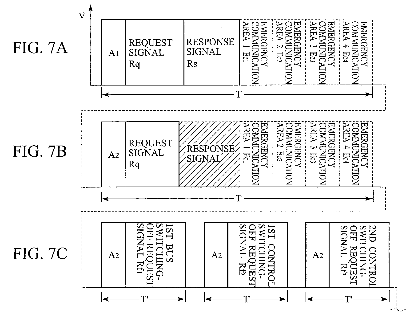
- the diagnosis section 10b performs the normal communication between the first satellite unit 11 and the master unit 10 (see Fig. 7A).
- the diagnosis section 10b outputs the address signal A 2 and the request signal Rq of the second satellite unit 12 to the second satellite unit 12.
- the response signal Rs in response to these signals cannot be received (the section of the shaded portion in Fig. 7B)
- a signal for turning OFF the first bus switch 12a, the first control switch 12b and the second control switch 12c is supplied to the second satellite unit 12 as the request signal (the section T' of Fig. 7C), and the first bus switch 12a, the first control switch 12b and the second control switch 12c are turned OFF.
- the command issuing section 16c makes the first circuit switching section 16b inoperative, and, at the same time, makes the second circuit switching section 16a operative, thus performing the initial setting processing (the section S of Fig. 7D). Thereafter, the command issuing section 16c performs the normal communication processing (the section U of Fig. 7E).
- the switching section 16 makes the second circuit switching section 16b operative in stead of the first circuit switching section 16a, and performs the initial setting processing in the order of the fourth satellite unit 14, the third satellite unit 13, the second satellite unit 12 and the first satellite unit 11.
- the slave unit can always transmit information to the master unit if necessary, there is no time delay in transmitting the information. and the information can be transmitted promptly. An interruption is available even when the number of the connections of the slave units is made large, and communication trouble does not occur at all in the information transmission from the slave unit.
- the collision information can be always transmitted to the master unit promptly without time delay.
- the interruption is available when the collision occurs. Accordingly, the transmission of the collision information can be performed timely.
Abstract
Description
- The present invention relates to a multiplex communication system and a car-passenger protection system using the same. Conventionally, a multiplex communication system as shown in Fig. 1 is known. Specifically, a
master unit 100 includes amicrocomputer 101 and an acceleration sensor. Themaster unit 100 is coupled to a plurality ofsatellite units reference bus 102, and coupled to the plurality ofsatellite units signal transmission bus 104.Squibs satellite units - The
satellite units 103A to 103N are located on the side portion of a car such as a door panel apart from themaster unit 100 positioned at he center of the car. Signals are respectively supplied to thesatellite units 103A to 103N through thesignal transmission bus 104 from themaster units 100. Electric energy is supplied to each of thesatellite units 103A to 103N by voltage multiplexing. A part of the electric energy transmitted to each of thesatellite units 103A to 103N is used for allowing thesatellite unit 103A to 103N to operate. Other parts are stored in thesatellite unit 103A, and the electric energy stored in thesatellite unit 103A is supplied to thesquib 105A as ignition current when an airbag needs to be developed at the time of an accident. There is a technology disclosed in Japanese Patent Laid-Open No. 10(1998)-154992 as such kinds of prior arts. - However, in the system having the above described construction, when any of the satellite units detects a collision, there has been a problem that the satellite unit, which detected the collision, cannot inform the master unit of that the satellite unit detected the collision by transmitting a response signal until a signal for requesting to inform whether or not the collision happened is transmitted from the master unit to this satellite unit. Therefore, when the number of the satellite units increases, it takes much time to verify for the satellite units sequentially whether detection has been made or not. Accordingly, when a specific satellite unit detects acollision, there has been an apprehension that this specific satellite unit cannot inform the master unit of the detection of the collision by transmitting a response signal, at maximum until confirmation procedures for all of other satellite units have been completed.
- The present invention was made to solve the above described problems, and an object of the present invention is to make it possible to transmit data, which must be transmitted immediately from a satellite unit to a master unit, immediately without delay when the data is transmitted.
- According to a first aspect of the present invention, a multiplex communication system comprises a master unit and a plurality of slave units. The master unit and the plurality of slave units are coupled to each other by a signal line annularly. The master unit transmits a request signal to each of the slave units through the signal line, and receives a response signal in response to the request signal from each of the slave units. The response signal has a data area to which each of the slave units can write data.
- According to a second aspect of the present invention, a car-passenger protection system comprises a master unit for judging a scale of collision from a first direction; a plurality of slave units include first and second slave units, the first slave unit judging a scale of collision from a second direction and the second slave unit judging a scale of collision from a third direction: and a squib operated by a control of the master unit, wherein the master unit and the plurality of slave unit are connected by a signal line annularly, and the master unit transmits a request signal to each of the slave units via the signal line and receives a response signal in response to the request signal from each of the slave units, and wherein the response signal has a data area to which each slave unit can write data, and data which indicate an occurrence of the collision is written to the data area when each slave unit detects the collision.
-
- Fig. 1 is an explanatory view schematically illustrating the entire configuration of a conventional airbag unit.
- Fig. 2 is an explanatory view illustrating a circuit block of a car-passenger protection device for a car-passenger device using a multiplex communication circuit, which shows an embodiment of the present invention.
- Fig. 3 is an explanatory view illustrating a circuit block of a car-passenger protection device using amultiplex communication circuit, which shows an embodiment of the present invention.
- Fig. 4 is an explanatory view illustrating a circuit block of a car-passenger protection device using a multiplex communication circuit, which shows an embodiment of the present invention.
- Fig. 5 is a flowchart of an operation of the devices illustrated in Figs. 2 to 4.
- Figs. 6A to 6D are each a time chart for explaining the operation Figs. 2 to 4, Fig. 6A for initial setting during normal communication. Fig. 6B for initial setting during trouble communication, Fig. 6C for normal communication, and Fig. 6D for trouble communication.
- Figs. 7A to 7E are each a time chart for explaining the operation Figs. 2 to 4.
- Fig. 8(8A to 8C) is a flowchart at the time the devices illustrated in Figs. 2 to 4 are initially set.
- Fig. 9 is a flowchart at the time the devices illustrated in Figs. 2 to 4 are initially set.
- Fig. 10 is a flowchart during normal operations of the devices illustrated in Figs. 2 to 4.
-
- A multiplex communication system according to the preferred embodiment of the present invention is shown in Fig. 2, and Fig. 2 is a drawing illustrating a system configuration of an airbag control device (a car-passenger protection device).
- For example, a
first satellite unit 11 is a driver's seat-side acceleration sensor unit, asecond satellite unit 12 is a driver's seat-side airbag developing and driving circuit, athird satellite unit 13 is a front seat-side acceleration sensor unit, and afourth satellite unit 14 is a front seat-side developing and driving circuit. Although aswitching control section 16 is illustrated in Fig. 2 as a different circuit block from themaster unit 10, theswitching control section 16 constitute a part of themaster unit 10, practically. - The first to
fourth satellite units 11 to 14 and theswitching control section 16 are annularly and electrically coupled by onecommunication line 15 to be in the form of voltage multiplex communication configuration. Power in which various signals containing data are superimposed is supplied from themaster unit 10 to the first to fourth satellite units by thecommunication line 15 constituted bycommunication lines 15a to 15e coupled in series. Specifically, thecommunication line 15 serves also as a power supply line as well as the signal line. The first tofourth satellite units 11 to 14 constitute a slave unit. - Detailed configurations of the
master unit 10, theswitching control section 16 and the first tofourth satellite units 11 to 14 will be described. - The
master unit 10 as a controller has approximately the same functions as thecenter unit 3 in the prior art. Specifically, themaster unit 10 is constituted by a microcomputer including acollision judgment section 10a, adiagnosis section 10b and amultiplex communication section 10c, apower source circuit 10d an acceleration sensor for the front andback direction 10e and the like. Thediagnosis section 10b and themultiplex communication section 10c are coupled to thecommunication line 15a through a firstcircuit switching section 16a of aswitching control section 16, and coupled to acommunication line 15e through a secondcircuit switching section 16b. - The
switching control section 16 comprises microcomputers providing a firstcircuit switching section 16a, the secondcircuit switching section 16b, a command issuingsection 16c and the like and aDC power source 16d for supplying current to the microcomputers. The command issuingsection 16c alternately activates the first andsecond switching sections collision judgment section 10a and thediagnosis section 10b in themaster unit 10. Then, upon power-on, based on instructions from thecollision judgment section 10a and thediagnosis section 10b in themaster unit 10, the command issuingsection 16c superimposes a signal for supplying addresses and various request signals to the respective first tofourth satellite units 11 to 14, on a DC output from thepower source circuit 10d, and outputs the superimposed signal to the communication line through one of the circuit switching section, which has been activated. - After the command issuing
section 16c activates the firstcircuit switching section 16a, the command issuingsection 16c executes an initial setting processing A in the flowchart as illustrated in Fig. 5. When it is judged to be normal, the procedure advances to a communication trouble detection processing B, followed by a normal communication processing C. - in the initial setting processing A, when the
diagnosis section 10b of themaster unit 10 judges that communication failure has occurred in any of thecommunication line 15 or the first tofourth satellite units 11 to 14, then the command issuingsection 16c inactivates the firstcircuit switching section 16a and, at the same time, activates the secondcircuit switching section 16b, based on the instruction of thediagnosis section 10b of themaster unit 10, and proceeds to the initial setting processing A, the communication trouble detection processing B, the normal communication processing C, the communication trouble occurrence point detection D, and the communication trouble occurrence point cutting and communication reconstruction E according to the flowchart as illustrated in Fig. 3. - When it is judged that communication failure has occurred in any of the
communication line 15 and the first tofourth satellite units 11 to 14 during the normal communication, the command issuingsection 16c inactivates, for example, the firstcircuit switching section 16a and, at the same time, activates the secondcircuit switching section 16b, based on the instruction of thediagnosis section 10b of themaster unit 10, and proceeds to the initial setting processing A, the communication trouble detection processing B, the normal communication processing C, the communication trouble occurrence point detection D, and the communication trouble occurrence point cutting and communication reconstruction E according to the flowchart as illustrated in Fig. 5. - On the contrary, when the second
circuit switching section 16b is activated, the firstcircuit switching section 16a is simultaneously activated. - The
first satellite unit 11 comprises a first bus switch (first switchingmeans) 11a, afirst control switch (second switching means) 11b, a second control switch (third control switching means) 11c, a first circuitvoltage monitor circuit 11d, a second circuit monitor circuit 11e, afirst interface 11h, a command decoding circuit (constituted by a microcomputer) 11f, a firstDC power source 11g, and the like. The first bus switch 11a is arranged between thecommunication lines second control switches second control switches - The first circuit
voltage monitor circuit 11d monitors the voltage of thesignal line 15a coupled to one I/O terminal of two I/O terminals of thefirst satellite unit 11, and detects the trailing edge of a voltage of the first address signal from the command issuingsection 16c, which was superimposed on the first constant voltage obtained after thepower source circuit 10d in themaster unit 10 begins to operate, thus turning on thefirst control switch 11b. - The second circuit voltage monitor circuit 11e is coupled to the other I/O terminal of the
first satellite unit 11, and monitors the voltage of thesignal line 15b which is obtained after resetting the first tofourth satellite units 11 to 14 when communication trouble occurs in thecommunication line 15 or any of the first tofourth satellite units 11 to 14 after the operation start of thepower source circuit 10d in themaster unit 10. Then, by the instruction of the switchingcontrol section 16, the second circuit voltage monitor circuit 11e detects the trailing edge of the voltage of the first address signal to be voltage-multiplexed on thesignal line 15b, turning on thesecond control switch 11c. - The
first interface 11h has an I/O terminal coupled to the connection node of the first and second control switches 11b and 11c coupled to each other in series. Upon receipt of the address signal and the request signal from thecommunication line 15, thefirst interface 11h supplies the address signal and the request signal to the firstcommand decoding circuit 11f, and outputs a response signal and an airbag developing request signal, which are output from the firstcommand decoding circuit 11f, onto thecommunication line 15. - When the address signal is supplied to the first
command decoding circuit 11f, the firstcommand decoding circuit 11f allows themaster unit 10 and the switchingcontrol section 16 to store the address signal as an inherent address signal in thememory 11i, this address signal being for discriminating its own unit (first satellite unit 11) from the first tofourth satellite units 12 to 14, and performs the initial setting, thus turning ON the first bus switch 11a. - The first
command decoding circuit 11f makes self-diagnosis for the unit including thecircuit 11f always. When the request signal is supplied to the firstcommand decoding circuit 11f, the firstcommand decoding circuit 11f outputs the result of the self-diagnosis result to thefirst interface 11h. On the other hand, as the result of the self-diagnosis, when it is judged that communication trouble has occurred in its own circuit, that is, thefirst satellite unit 11, the firstcommand decoding circuit 11f turns-off the first bus switch 11a, thefirst control switch 11b and thesecond control switch 11c, and abandons the address stored in thememory 11i. Furthermore, the firstcommand decoding circuit 11f makes the firstDC power source 11g compulsorily inoperative, and allows the charges stored in a capacitor constituting the firstDC power source 11g to discharge, thus disabling the secondDC power source 11g from restarting. Accordingly, a possibility of an occurrence of a malfunction is completely removed. specifically, an initial setting is performed. - The
third satellite unit 13 also has the same configuration as that of thefirst satellite unit 11. A first bus switch (first switch means) 13a corresponds to the first bus switch 11a of thefirst satellite unit 11, and a first control switch (second control switch means) 13b corresponds to thefirst control switch 11b of thefirst satellite unit 11. The second control switch (third switch means) 13c corresponds to thesecond control switch 11c of thefirst satellite unit 11. A first circuitvoltage monitor circuit 13d corresponds to the first circuitvoltage monitor circuit 11d of thefirst satellite unit 11, and a second circuitvoltage monitor circuit 13e corresponds to the second circuit voltage monitor circuit 11e of thefirst satellite unit 11.Afirst interface 13f corresponds to thefirst interface 11f of thefirst satellite unit 11, and acommand decoding circuit 13g corresponds to the firstcommand decoding circuit 11f of thefirst satellite unit 11. Asecond DC source 13h corresponds to thesecond DC source 11h of thefirst satellite unit 11. - The second and
fourth satellite units first satellite unit 11. First bus switches (first switch means) 12a and 14a correspond to the first bus switch 11a of thefirst satellite unit 11, and first control switches (second switch controller) 12b and 14b correspond to thefirst control switch 11b of thefirst satellite unit 11. Second control switches (third switch means) 12c and 14c correspond to thesecond control switch 11c of thefirst satellite unit 11, and first circuitvoltage monitor circuit 12d and 14d correspond to the first circuitvoltage monitor circuit 11d of thefirst satellite 11. Second circuitvoltage monitor circuit first satellite unit 11, andfirst interfaces first interface 11f of thefirst satellite unit 11.Command decoding circuits command decoding circuit 11f of thefirst satellite unit 11, and secondDC power sources second DC source 11h of thefirst satellite unit 11. - The first and
third satellite units fourth satellite units acceleration sensors third satellite units squibs fourth satellite units acceleration sensors - The outline of the control for the switching
control section 16 of themaster unit 10 is illustrated in the flowchart of Fig. 5, and the detailed flowcharts of each block in this flowchart are illustrated in Figs. 8 and 9. - First, the description for the total outline of the communication function of the
master unit 10 will be made based on the flowchart illustrated in Fig. 5. - After the initial setting processing A is performed accompanied with the power-on, the procedure advances to the next step B.
- The communication trouble detection processing is first performed in step B, and thus it is detected whether the communication trouble has occurred. When it is judged that the communication trouble has not occurred, the operation of the normal communication processing is performed in next step C. When it is judged in step B that the communication trouble has occurred, the communication trouble occurrence point detection processing is performed in next step D, and an abnormal point where the communication trouble has occurred is decided. In next step E, the communication trouble point cutting processing to cut off the communication trouble occurrence point, that is, an abnormal point, from the multiplex communication link and the reconstruction processing of the communication circuit network are performed, and then the procedure advances to the normal communication processing of step C. After completion of step C, the procedures returns to step B, and steps C. D and E are repeatedly executed. Descriptions for steps will be described below.
- The communication trouble occurrence detection in the initial setting processing in step A of Fig. A will be described.
- When the procedure advances to step A for this initial setting processing, the
command issuing section 16c activates the firstcircuit switching section 16a. On the other hand, thecommand issuing section 16c inactivates the second circuit switching section l6b, and outputs an address and request signal of thefirst satellite unit 11 onto thesignal line 15a. A response signal in response to the request signal, the response signal being supplied from thefirst satellite unit 11 and indicating that the communication circuit is normal is confirmed. The same operation as this confirmation operation is sequentially performed for the second tofourth satellite units 12 to 14 by accessing to them, and the diagnosis as to whether the communication trouble has occurred is performed for them, respectively. The procedure advances to next step B. - Specifically, for the communication between the
master unit 10 and the first tofourth satellite units 11 to 14, the predetermined time T per one frame is given as a setting value, and one frame is basically composed of the portion of the address signal A, the portion of the request signal Rq, and the portions of the first to fourth satellite emergency communication areas Ec1 to Ec4. - The operation of the multiplex communication system will be concretely described based on the flowchart illustrated in Fig. 8. When the power source is tuned on, in step A, the
command issuing section 16c activates only the firstcircuit switching section 16a in response to the instruction from thecommand issuing section 16c, in order to transmit the output signal (the address signal A, and the request signal Rq) from thecommand issuing section 16c in, for example, the clockwise direction (the A-direction illustrated in Fig. 2) (step ST210). When the firstcircuit switching section 16a is normally activated, thecommand issuing section 16c outputs the address signal A and the request signal Rq sequentially to the first tofourth satellite units 11 to 14. Herein, since the initial setting processing for each of the first tofourth satellite units 11 to 14 is performed in the same manner, the processing for thefirst satellite unit 11 is representatively described below. First, thecommand issuing section 16 c verifies the response signal Rs which is output from thefirst satellite unit 11 in response to the request signal Rq which is output in step S220, the response signal Rs indicating that the communication circuit is in a normal state. When it is judges that it is possible to perform the communication normally, a signal Rs indicating that it is possible to perform the communication normally is supplied to thediagnosis section 10b of themaster unit 10, and the procedures advances to step ST230 of step B. - On the other hand, when the
diagnosis section 10b judges that the signal Rs indicating that the communication is performed normally is not confirmed after waiting the signal Rs for a predetermined time (steps ST220 and ST240), thediagnosis section 10b instructs the command issuing section 19 to inactivate the firstcircuit switching section 16a (step ST250). Alternatively, thediagnosis section 10b instructs the command issuing section 19 to activate the secondcircuit switching section 16b (step ST260). As a result, the output signal (the address signal and the request signal) from thecommand issuing section 16c is transmitted, for example, in the counterclockwise direction (the B-direction illustrated in Fig. 2). Specifically, the diagnosis which is performed in the same manner as that for the firstcircuit switching section 16a is performed for the secondcircuit switching section 16b in the reverse order as illustrated in Fig. 6B, that is, in the order of the fourth satellite unit 14 (fourth frame F4), the third satellite unit 13 (third frame F3), the second satellite unit 12 (second frame F2), and the first satellite unit 11 (first frame F1). - In step ST230, the
command issuing section 16c allows the firstcircuit switching section 16a to output the address signal A and the request signal Rq to communicate with thefirst satellite unit 11 onto thecommunication line 15 while superimposing them on the power source voltage. In step ST270, it is judged whether the first circuitvoltage monitor circuit 11d of thefirst satellite unit 11 has received the address signal and the request signal from thecommunication line 15a. When it is judged based on the response signal Rs that the address signal A and the request signal Rq have received, the procedure advances to step ST280. - On the other hand, when it is judged that the first circuit
voltage monitor circuit 11d has not received the address signal A and the request signal Rq yet, steps ST270 and ST290 are executed repeatedly to wait the acceptance of the address signal A and the request signal Rq while a predetermined time passes. When it is judged that the address signal A and the request signal Rq are not received after the passage of the predetermined time, the procedures advances to step ST300. In step ST300, thediagnosis section 10b instructs thecommand issuing section 16c to inactivate the firstcircuit switching section 16a (step ST300), and the procedures advances to step ST260. Alternatively, thediagnosis section 10b instructs the command issuing section 19 to activate the secondcircuit switching section 16b. - In step ST270, when the first circuit
voltage monitor circuit 11d receives the first voltage change of the signal indicating the address, thefirst control switch 11b is changed to be in ON in step ST280, and the address signal and the request signal are supplied to the firstcommand decoding circuit 11f. - When the address signal and the request signal supplied to the
first decoding circuit 11f is normally decoded and the address signal is stored in thememory 11i, the procedure advances to step ST310. And the response signal Rs indicating that decoding and storing are normally performed is outputted from the firstcommand decoding circuit 11f onto thecommunication line 15a via thefirst interface 11h. The response signal Rs is sent back to thediagnosis section 10b of themaster unit 10. When it is judged by thediagnosis section 10b that the response signal is received, the procedures advances to step ST320 from step ST310. - However, when it is judged that the response signal Rs is not received, the response signal Rs is waited for a predetermined time in step ST330. When the response signal Rs is not received after waiting the response signal Rs for the predetermined time, a signal indicating the occurrence of the communication trouble is supplied to the
diagnosis section 10b (step ST340), and thediagnosis section 10b instructs thecommand issuing section 16c to inactivate the firstcircuit switching section 16a (step ST350). The instruction to turn OFF all of the switches 11a to 14a, 11b to 14b, 11c to 14c, and 11d to 14d of the first tofourth satellite units 11 to 14 is made (step ST380), and the procedure advances to step ST260. - In step ST310, when the address signal is stored in the
memory 11i and the procedure advances from step ST310 to step ST320, a signal to turn ON the first bus switch 11a of thefirst satellite unit 11 is issued from thecommand issuing section 16c to the firstcircuit switching section 16a, whereby the firstcircuit switching section 16a is requested to output the address signal and the request signal onto thecommunication line 15, these signals indicating the instruction to turn ON the first bus switch 11a. The first command monitor section 26 of thefirst satellite unit 11 recognizes it, and turns ON the first switch 11a. When it is confirmed by thediagnosis section 10b that the first bus switch 11a is turned ON (step ST390), the procedures advances to the flowchart of the initial setting processing for thesecond satellite unit 12, which is illustrated in the block C performed as step A' of Fig. 9. - The flowchart of step A' is executed substantially in the same manner as step A performed for the
first satellite unit 11. - On the other hand, in step ST390, the response signal is output from the first
command decoding circuit 11f onto thecommunication line 15a via thefirst interface 11h, and sent back to thediagnosis section 10b of themaster unit 10. When the response signal is waited by thediagnosis section 10b for a predetermined time (step ST410), and when the response signal is not sent back, it is judged that communication trouble has occurred in the first satellite unit 11 (step ST410), and thediagnosis section 10b instructs the command issuing section 19 to inactivate the firstcircuit switching section 16a (step ST420). In step ST430, the instruction to turn OFF all of the switches 11a to 11e, 12a to 12e, 13a to 13e, and 14a to 14e of the first tofourth satellite units 11 to 14 is made, and the procedure advances to step ST260. - Thereafter, the procedure advances to step A' of Fig. 9, and the initial setting processing for the
second satellite unit 12 is performed. When the initial setting processing is completed, the procedure advances to the flowchart, which is illustrated in the block D performed as step A'' of Fig. 9. Also when the procedure advances to the initial setting processing of thethird satellite unit 13, and also when the procedure advances to step A''' of the initial setting processing for thefourth satellite unit 14 after the initial setting processing for thefourth satellite unit 14, the same step is sequentially executed in the same manner as described above. When the steps are normally completed, the procedure advances to the communication trouble detection processing of step B in Fig. 5. - However, as described above, if the initial setting processing to perform the communication in the order of the first, second, third and
fourth satellite units 11 to 14 could not executed, the initial setting processing is executed in the reverse direction to the above, that is, the firstcircuit switching section 16a is inactivated and the secondcircuit switching section 16b is activated. As shown in Fig. 6B, the initial setting processing to perform the communication in the order of the fourth, third, second andfirst satellite units 14 to 11 is executed, and the procedure advances to the normal communication. When both of the first andfourth satellite units - The communication trouble detection processing is performed by recognizing the point judged to be incapable of performing the communication by performing the same processing as that performed in step A of Fig. 5.
- As a result of the foregoing initial setting processing, when it is judged that the communication is performed normally, the normal communication processing (step C of Fig. 5) to be described below is performed in accordance with the flowchart based on Fig. 10.
- The normal communication processing is performed in the same communication method as the communication at the time of a star connection in the multiplex communication. The detail of the normal communication processing is described below.
- Accompanied with the powered on by turning ON an ignition switch, when the
master unit 10 starts to operate in the state where the firstcircuit switching section 16a is usually operative and the secondcircuit switching section 16b is inoperative, the procedures advances to step ST500. Specifically, themultiplex communication section 10c performs the communication sequentially with the first, second, third and fourth satellite units 11to 14 via thecommunication line 15a, in which the address signal A, the request signal Rq, the response signal Rs and the developing request address write area Ec1, Ec2, Ec3 and Ec4 shown in Fig. 6C are packed in one frame, and a satellite unit for which this communication is performed is assigned by an address signal supplied to thecommunication line 15a this time. - Specifically, if the supplied address signal coincides with an address signal stored in the
memory 11i of thefirst satellite unit 11 in the initial setting processing (step ST510), themultiplex communication section 10c performs the communication with thefirst satellite unit 11. If the supplied address signal coincides with an address signal stored in thememory 12i of the second satellite unit 12 (step ST510), themultiplex communication section 10c performs the communication with thesecond satellite unit 12. - The
multiplex communication section 10c performs the communication in the same manner for the third andfourth satellite units 13 and 14., respectively. - As a typical example, the communication between the
diagnosis section 10b and the first andsecond satellite units - In the
first satellite unit 11, the request signal of the first frame illustrated in Fig. 6A, that is, the request signal Rq illustrated in Fig. 6C is supplied to thefirst satellite unit 11, and thefirst command signal 11f decodes the request signal. When the response signal Rs (see Fig. 6C) in response to the request signal is supplied to thediagnosis section 10b from thefirst satellite unit 11 via themultiplex communication section 10c after passing through thecommunication line 15a, diagnosis as to whether the communication trouble has occurred in thefirst satellite unit 11 and on thecommunication line 15a is performed in thediagnosis section 10b. - Then, this diagnosis is performed also for the
second satellite unit 12 in the same manner as that for thefirst satellite unit 11. The response signal Rs is supplied to thediagnosis section 10b from themultiplex communication section 10c, and diagnosis as whether the communication trouble has occurred in thesecond satellite unit 12 is performed. - In the initial setting processing illustrated in step A of Fig. 10, when the confirmation for the first
circuit switching section 16a is not performed even after a predetermined time is needed (step ST520), the procedure advances to step ST530. In step ST530, the secondcircuit switching section 16b becomes operative, and the firstcircuit switching section 16a becomes inoperative. In this state, when themaster unit 10 starts to operate, the communication is performed in the order of the fourth, third, second andfirst satellite units 14 to 11 (step ST540). - The communication with the
second satellite unit 12 will be described. For example, when the communication between thediagnosis section 10b and thefirst satellite unit 11 is performed in the normal communication processing, the case where thethird satellite unit 13 detects that something collided against the car from its transverse direction (right or left of the car) at the time X in Fig. 6A will be described as an example below. - At the time X while the communication of the request signal and the response signal is being performed between the
diagnosis section 10b and thefirst satellite unit 11, when thethird satellite unit 13, for example, detects the collision from the transverse direction of the car by the transversedirection acceleration sensor 13j, the thirdcommand decoding circuit 13f of thethird satellite unit 13 writes collision data in the specific third satellite emergency communication area Ec3 as shown in Fig. 6, the collision data indicating that the collision from the transverse direction of the car has occurred (the shaded area of Fig. 6D). - When the
collision judgment section 10a of themaster unit 10 receives the collision data Dc written in the specific area, thecollision judgment section 10a does not perform the communication with thesecond satellite unit 12 during the section Y-Y', and skips across the section Y-Y'. In order to start the multiplex communication with thethird satellite unit 13 which transmits the data indicating the occurrence of the collision, thecollision judgment section 10a supplies the address signal and the request signal illustrated in the first section T' of Fig. 6 to thethird satellite unit 13 via thecommunication lines 15c to 15a. - As a result, the command decoding section 31 of the
third satellite unit 13 supplies the response signal indicating the occurrence of the collision to thecollision judgment section 10a via the firstcircuit switching section 16a, and, against other developing conditions, thecollision judgment section 10a checks the fact that thethird satellite unit 13 detected the collision. As a result, when thecollision judgment section 10a judges that thethird satellite unit 13 detected the collision, thecollision judgment section 10a supplies the request signal via the signal line (15a to 15d) to thefourth satellite unit 14 for developing the side airbag, which makes a pair with thethird satellite unit 13. This request signal attaches an address of thefourth satellite unit 14 thereto, and corresponds to the address signal A4 and the request signal Xq illustrated in the second section T' from the left side of Fig. 6D. Furthermore, this signal instructs thefourth satellite unit 14 to perform a squib ignition. Thefourth satellite unit 14 supplies an ignition signal to a squib (not shown) and allows the airbag to develop itself. Thefourth satellite unit 14 sends back the developing completion data Xf to themultiplex communication section 10c as the response signal. - The fourth
command decoding section 14f of thefourth satellite unit 14 reads out the request signal Xq to instruct thefourth satellite unit 14 to perform the squib ignition via thecommunication lines 15a to 15d. When the fourthcommand decoding circuit 14f decodes the request, the fourthcommand decoding circuit 14f supplies ignition current to the squib, and allows the squib to develop the side airbag. - When it is judged during the normal communication processing that the communication trouble has occurred during the communication between the
multiplex communication 10c of themaster unit 10 and the first tofourth satellite units 11 to 14, the procedure advances to the communication trouble detection processing of step D and the communication trouble point cutting processing and the reconstruction processing of step E, which are illustrated in the flowchart of Fig. 5. - The procedures described above are performed sequentially for the
first satellite unit 11, thesecond satellite unit 12, thethird satellite unit 13 and thefourth satellite unit 14, and performed substantially in the same manner. Accordingly, a processing only for thefirst satellite unit 11 will be representatively made below. This processing is for steps D and E of Fig. 5. The total of the flowchart is described, and then its concrete example is described. - In Fig. 10, in step ST500, the
command issuing section 16c allows the firstcircuit switching section 16a to output the address signal A1 and the request signal Rq in thefirst satellite unit 11, and judges whether or not the response signal Rs in response to the request signal is sent back thereto within a predetermined time (steps S510 and S520). In step ST520, it is judged that the response signal is not sent back after passage of a predetermined time thediagnosis section 10b judges that the trouble communication has occurred between thefirst satellite unit 11 and themaster unit 10, and thediagnosis section 10b outputs the an instruction signal, which turns OFF the first bus switch 11a, to thecommand issuing section 16c. Thus, the first bus switch 11a is turned OFF, and thefirst satellite unit 11 is subsequently reset in step S540, wherebyother control switches - When it is judged that the
diagnosis section 10b receives the response signal, the procedures advances to the next block, and the same signal processing is performed also for thesecond satellite unit 12. subsequently, the procedure advances to the processing for the third andfourth satellite units - As shown in Fig. 7E, the
diagnosis section 10b performs the normal communication between thefirst satellite unit 11 and the master unit 10 (see Fig. 7A). Thediagnosis section 10b outputs the address signal A2 and the request signal Rq of thesecond satellite unit 12 to thesecond satellite unit 12. When the response signal Rs in response to these signals cannot be received (the section of the shaded portion in Fig. 7B), and when it is judged by thediagnosis section 10b of themaster unit 10 that the communication trouble has occurred in thesatellite unit 12, a signal for turning OFF thefirst bus switch 12a, thefirst control switch 12b and thesecond control switch 12c is supplied to thesecond satellite unit 12 as the request signal (the section T' of Fig. 7C), and thefirst bus switch 12a, thefirst control switch 12b and thesecond control switch 12c are turned OFF. - Thereafter, the
command issuing section 16c makes the firstcircuit switching section 16b inoperative, and, at the same time, makes the secondcircuit switching section 16a operative, thus performing the initial setting processing (the section S of Fig. 7D). Thereafter, thecommand issuing section 16c performs the normal communication processing (the section U of Fig. 7E). - Specifically, in order to start the communication among the
first satellite unit 11, thethird satellite unit 13 and thefourth satellite unit 14 except for thesecond satellite unit 12, the switchingsection 16 makes the secondcircuit switching section 16b operative in stead of the firstcircuit switching section 16a, and performs the initial setting processing in the order of thefourth satellite unit 14, thethird satellite unit 13, thesecond satellite unit 12 and thefirst satellite unit 11. However, prior to the initial setting processing, all of the first tofourth satellite units 11 to 14 are reset, and the address signals that have been stored in thememories 11i to 14i are abandoned, and the request signal for turning OFF all of the bus switches 11a to 14a and the control switches 11b to 14b and 11c to 14c is outputted, whereby the whole of the circuit system is reconstructed, and the processing is performed for the first, second, third andfourth satellite units - As described above, according to the first invention, since the slave unit can always transmit information to the master unit if necessary, there is no time delay in transmitting the information. and the information can be transmitted promptly. An interruption is available even when the number of the connections of the slave units is made large, and communication trouble does not occur at all in the information transmission from the slave unit.
- According to the second invention, when the slave unit detects the collision, the collision information can be always transmitted to the master unit promptly without time delay.
- Furthermore, even when the number of the connections of the slave units is large, the interruption is available when the collision occurs. Accordingly, the transmission of the collision information can be performed timely.
- Although the invention has been described above by reference to certain embodiments of the invention, the invention is not limited to the embodiments described above. Modifications and variations of the embodiments described above will occur to those skilled in the art, in light of the teachings. The scope of the invention is defined with reference to the following claims.
Claims (4)
- A multiplex communication system, comprising:a master unit; anda plurality of slave units connected to the master unit by a signal line annularly, the master unit transmitting a request signal to each of the slave units via the signal line and receiving a response signal in response to the request signal from each of the slave unit, whereinthe response signal has a data area writable by each of the slave units.
- The multiplex communication system according to claim 1, wherein the writable data area is set for each of the slave units.
- A car-passenger protection system comprising:a master unit for judging a scale of collision from a first direction, the master unit transmitting arequest signal via a signal line to a plurality of slave units and receiving a response signal in response to the request signal from each of the slave units;the plurality of slave units which are connected to the master unit by the signal line annularly and include first and second slave units, the first slave unit judging a scale of collision from a second direction and the second slave unit judging a scale of collision from a third direction; anda squib operated by a control of the master unit, whereinthe response signal has a data area writable by each of the slave units, to which data indicating an occurrence of the collision is written when each of the slave units detects the collision.
- The car-passenger protection system according to claim 3, wherein the writable data area is set for each of the slave units.
Applications Claiming Priority (2)
| Application Number | Priority Date | Filing Date | Title |
|---|---|---|---|
| JP2002052026A JP4037129B2 (en) | 2002-02-27 | 2002-02-27 | Multiple communication device and occupant protection device using the same |
| JP2002052026 | 2002-02-27 |
Publications (2)
| Publication Number | Publication Date |
|---|---|
| EP1349326A1 true EP1349326A1 (en) | 2003-10-01 |
| EP1349326B1 EP1349326B1 (en) | 2005-04-27 |
Family
ID=27800020
Family Applications (1)
| Application Number | Title | Priority Date | Filing Date |
|---|---|---|---|
| EP03004317A Expired - Lifetime EP1349326B1 (en) | 2002-02-27 | 2003-02-27 | Multiplex communication system and car-passenger protection system using the same |
Country Status (5)
| Country | Link |
|---|---|
| US (1) | US7546192B2 (en) |
| EP (1) | EP1349326B1 (en) |
| JP (1) | JP4037129B2 (en) |
| KR (1) | KR20030071532A (en) |
| DE (1) | DE60300557T2 (en) |
Cited By (2)
| Publication number | Priority date | Publication date | Assignee | Title |
|---|---|---|---|---|
| EP2110284A1 (en) * | 2008-04-18 | 2009-10-21 | Keihin Corporation | Passenger protection control device and passenger protection system |
| DE102016226136A1 (en) | 2016-12-23 | 2018-06-28 | Robert Bosch Gmbh | Method for operating a sensor device, sensor device |
Families Citing this family (8)
| Publication number | Priority date | Publication date | Assignee | Title |
|---|---|---|---|---|
| JP4305312B2 (en) * | 2004-07-20 | 2009-07-29 | 株式会社デンソー | Obstacle detection device |
| JP2006256371A (en) * | 2005-03-15 | 2006-09-28 | Toyota Motor Corp | Starter of occupant crash protection device |
| DE102006039709A1 (en) * | 2006-08-24 | 2008-02-28 | Robert Bosch Gmbh | Method for transmitting a drive decision for an actuator from a first to at least one second control device, first control device for a vehicle, second control device for a vehicle, device for transmitting a drive decision for an actuator from a first to a second control device |
| JP5045159B2 (en) * | 2007-03-12 | 2012-10-10 | 三菱電機株式会社 | Control subunit and control main unit |
| EP1977687A1 (en) | 2007-04-05 | 2008-10-08 | Koninklijke Philips Electronics N.V. | Hydrogel based device for detecting an environmental state |
| JP2010213168A (en) | 2009-03-12 | 2010-09-24 | Denso Corp | Communication apparatus |
| JP6640512B2 (en) * | 2015-09-29 | 2020-02-05 | エア・ウォーター防災株式会社 | Fire extinguisher |
| DE102018114225A1 (en) * | 2018-06-14 | 2019-12-19 | Valeo Schalter Und Sensoren Gmbh | Method for operating a sensor arrangement in a motor vehicle based on a DSI protocol |
Citations (5)
| Publication number | Priority date | Publication date | Assignee | Title |
|---|---|---|---|---|
| EP0280231A2 (en) * | 1987-02-23 | 1988-08-31 | Hitachi, Ltd. | Method and apparatus for detecting fault in ring network data transmission system |
| US5079759A (en) * | 1989-08-30 | 1992-01-07 | Mazda Motor Corporation | Multiplex transmission system for vehicles having a failure diagnosis function |
| US5305316A (en) * | 1990-09-04 | 1994-04-19 | Nissan Motor Co., Ltd. | Multiplex communication system |
| EP0802655A2 (en) * | 1996-04-17 | 1997-10-22 | Matsushita Electric Industrial Co., Ltd. | Communication network |
| EP1069733A2 (en) * | 1999-07-14 | 2001-01-17 | New Holland U.K. Limited | A controller area network |
Family Cites Families (17)
| Publication number | Priority date | Publication date | Assignee | Title |
|---|---|---|---|---|
| DE3816587A1 (en) * | 1988-05-16 | 1989-11-23 | Messerschmitt Boelkow Blohm | DEVICE FOR TRIGGERING A PASSIVE SAFETY DEVICE |
| JP2904283B2 (en) * | 1989-05-22 | 1999-06-14 | マツダ株式会社 | Multiplex transmission equipment for vehicles |
| US6733036B2 (en) * | 1995-06-07 | 2004-05-11 | Automotive Technologies International, Inc. | Automotive electronic safety network |
| US6532408B1 (en) * | 1997-05-29 | 2003-03-11 | Automotive Technologies International, Inc. | Smart airbag system |
| US5468013A (en) * | 1993-12-03 | 1995-11-21 | Trw Inc. | Dual air bag system for occupant restraint |
| JPH08246512A (en) * | 1995-03-07 | 1996-09-24 | Shinwa Musen Syst Kk | Water leak detector |
| US5760489A (en) | 1996-10-04 | 1998-06-02 | Motorola, Inc. | Method for transmitting signals between a microprocessor and an interface circuit |
| US5964816A (en) * | 1998-01-26 | 1999-10-12 | Delco Electronics Corp. | Address communication method for a distributed architecture supplemental inflatable restraint system |
| DE19813957C2 (en) * | 1998-03-28 | 2003-06-18 | Conti Temic Microelectronic | Occupant protection system with a central unit, sensors and several control modules communicatively connected by means of a BUS system for triggering occupant protection devices |
| US6166653A (en) * | 1998-08-13 | 2000-12-26 | Motorola Inc | System for address initialization of generic nodes in a distributed command and control system and method therefor |
| JP3640143B2 (en) * | 1998-12-25 | 2005-04-20 | 日産自動車株式会社 | Crew protection device |
| JP4465767B2 (en) * | 1999-12-28 | 2010-05-19 | マツダ株式会社 | Deployment control device for airbag device |
| DE10084602B4 (en) * | 2000-03-17 | 2004-02-26 | Mitsubishi Denki K.K. | Collision detection procedure and passive safety device |
| US6744820B1 (en) * | 2000-03-21 | 2004-06-01 | Trw Inc. | Communication system and method utilizing message frames having multiple thresholds for a multi-device vehicle occupant protection system |
| US6536798B1 (en) * | 2000-09-27 | 2003-03-25 | Aùtoliv ASP, Inc. | Controlling activation of restraint devices in a vehicle |
| US6922547B2 (en) * | 2001-06-27 | 2005-07-26 | Flarion Technologies, Inc. | Methods and apparatus for supporting group communications |
| US7082485B2 (en) * | 2002-07-24 | 2006-07-25 | The Boeing Company | Systems and methods for establishing peer-to-peer communications between network devices communicating via a common bus |
-
2002
- 2002-02-27 JP JP2002052026A patent/JP4037129B2/en not_active Expired - Fee Related
-
2003
- 2003-02-26 KR KR10-2003-0012073A patent/KR20030071532A/en active IP Right Grant
- 2003-02-26 US US10/373,200 patent/US7546192B2/en not_active Expired - Fee Related
- 2003-02-27 DE DE60300557T patent/DE60300557T2/en not_active Expired - Fee Related
- 2003-02-27 EP EP03004317A patent/EP1349326B1/en not_active Expired - Lifetime
Patent Citations (5)
| Publication number | Priority date | Publication date | Assignee | Title |
|---|---|---|---|---|
| EP0280231A2 (en) * | 1987-02-23 | 1988-08-31 | Hitachi, Ltd. | Method and apparatus for detecting fault in ring network data transmission system |
| US5079759A (en) * | 1989-08-30 | 1992-01-07 | Mazda Motor Corporation | Multiplex transmission system for vehicles having a failure diagnosis function |
| US5305316A (en) * | 1990-09-04 | 1994-04-19 | Nissan Motor Co., Ltd. | Multiplex communication system |
| EP0802655A2 (en) * | 1996-04-17 | 1997-10-22 | Matsushita Electric Industrial Co., Ltd. | Communication network |
| EP1069733A2 (en) * | 1999-07-14 | 2001-01-17 | New Holland U.K. Limited | A controller area network |
Cited By (2)
| Publication number | Priority date | Publication date | Assignee | Title |
|---|---|---|---|---|
| EP2110284A1 (en) * | 2008-04-18 | 2009-10-21 | Keihin Corporation | Passenger protection control device and passenger protection system |
| DE102016226136A1 (en) | 2016-12-23 | 2018-06-28 | Robert Bosch Gmbh | Method for operating a sensor device, sensor device |
Also Published As
| Publication number | Publication date |
|---|---|
| JP2003258821A (en) | 2003-09-12 |
| DE60300557T2 (en) | 2005-09-29 |
| US20040024832A1 (en) | 2004-02-05 |
| US7546192B2 (en) | 2009-06-09 |
| JP4037129B2 (en) | 2008-01-23 |
| EP1349326B1 (en) | 2005-04-27 |
| DE60300557D1 (en) | 2005-06-02 |
| KR20030071532A (en) | 2003-09-03 |
Similar Documents
| Publication | Publication Date | Title |
|---|---|---|
| JP2815441B2 (en) | Electronic equipment | |
| US5357141A (en) | Electronic device | |
| US7864028B2 (en) | In-vehicle emergency call apparatus | |
| KR100639524B1 (en) | Method for data transfer in a restraint system connected to a bus line | |
| JP3438217B2 (en) | Method and apparatus for controlling data transmission between two modules provided in a motor vehicle | |
| EP1349326A1 (en) | Multiplex communication system and car-passenger protection system using the same | |
| JP4650690B2 (en) | Bus communication system | |
| JP2949998B2 (en) | Communication device | |
| JP4591383B2 (en) | Bus communication system | |
| JP2006301952A (en) | Vehicular usb system and onboard radio communication device | |
| EP2110284B1 (en) | Passenger protection control device and passenger protection system | |
| US6293583B1 (en) | Apparatus for activating passive safety device | |
| JP3714111B2 (en) | Vehicle occupant protection system | |
| JP4037115B2 (en) | Multiple communication device and vehicle occupant protection device using the same | |
| JP3298290B2 (en) | Multiplex communication device | |
| JP3916495B2 (en) | Controller with fail-safe function | |
| JPH04275740A (en) | On-vehicle multiplex transmission device | |
| JP3247209B2 (en) | Multiplex transmission equipment | |
| JPH1117716A (en) | Data communication circuit | |
| JP3084984B2 (en) | Airbag control device | |
| JP3184343B2 (en) | Multiplex transmission equipment | |
| JP2001001859A (en) | Occupant crash protection system | |
| JP3383462B2 (en) | Multiplex transmission system | |
| JPH01143533A (en) | Multiplex transmission system | |
| JPH10129421A (en) | Anti-theft device for vehicle |
Legal Events
| Date | Code | Title | Description |
|---|---|---|---|
| PUAI | Public reference made under article 153(3) epc to a published international application that has entered the european phase |
Free format text: ORIGINAL CODE: 0009012 |
|
| AK | Designated contracting states |
Kind code of ref document: A1 Designated state(s): AT BE BG CH CY CZ DE DK EE ES FI FR GB GR HU IE IT LI LU MC NL PT SE SI SK TR |
|
| AX | Request for extension of the european patent |
Extension state: AL LT LV MK RO |
|
| 17P | Request for examination filed |
Effective date: 20040312 |
|
| 17Q | First examination report despatched |
Effective date: 20040414 |
|
| AKX | Designation fees paid |
Designated state(s): DE FR GB |
|
| GRAP | Despatch of communication of intention to grant a patent |
Free format text: ORIGINAL CODE: EPIDOSNIGR1 |
|
| GRAS | Grant fee paid |
Free format text: ORIGINAL CODE: EPIDOSNIGR3 |
|
| GRAA | (expected) grant |
Free format text: ORIGINAL CODE: 0009210 |
|
| AK | Designated contracting states |
Kind code of ref document: B1 Designated state(s): DE FR GB |
|
| REG | Reference to a national code |
Ref country code: GB Ref legal event code: FG4D |
|
| REG | Reference to a national code |
Ref country code: IE Ref legal event code: FG4D |
|
| REF | Corresponds to: |
Ref document number: 60300557 Country of ref document: DE Date of ref document: 20050602 Kind code of ref document: P |
|
| PLBE | No opposition filed within time limit |
Free format text: ORIGINAL CODE: 0009261 |
|
| STAA | Information on the status of an ep patent application or granted ep patent |
Free format text: STATUS: NO OPPOSITION FILED WITHIN TIME LIMIT |
|
| ET | Fr: translation filed | ||
| 26N | No opposition filed |
Effective date: 20060130 |
|
| PGFP | Annual fee paid to national office [announced via postgrant information from national office to epo] |
Ref country code: DE Payment date: 20090219 Year of fee payment: 7 |
|
| PGFP | Annual fee paid to national office [announced via postgrant information from national office to epo] |
Ref country code: GB Payment date: 20090225 Year of fee payment: 7 |
|
| REG | Reference to a national code |
Ref country code: GB Ref legal event code: 746 Effective date: 20090924 |
|
| PGFP | Annual fee paid to national office [announced via postgrant information from national office to epo] |
Ref country code: FR Payment date: 20090213 Year of fee payment: 7 |
|
| GBPC | Gb: european patent ceased through non-payment of renewal fee |
Effective date: 20100227 |
|
| REG | Reference to a national code |
Ref country code: FR Ref legal event code: ST Effective date: 20101029 |
|
| PG25 | Lapsed in a contracting state [announced via postgrant information from national office to epo] |
Ref country code: FR Free format text: LAPSE BECAUSE OF NON-PAYMENT OF DUE FEES Effective date: 20100301 |
|
| PG25 | Lapsed in a contracting state [announced via postgrant information from national office to epo] |
Ref country code: DE Free format text: LAPSE BECAUSE OF NON-PAYMENT OF DUE FEES Effective date: 20100901 |
|
| PG25 | Lapsed in a contracting state [announced via postgrant information from national office to epo] |
Ref country code: GB Free format text: LAPSE BECAUSE OF NON-PAYMENT OF DUE FEES Effective date: 20100227 |