JP4029102B2 - Video game program, video game apparatus, and video game control method - Google Patents
Video game program, video game apparatus, and video game control method Download PDFInfo
- Publication number
- JP4029102B2 JP4029102B2 JP2005372073A JP2005372073A JP4029102B2 JP 4029102 B2 JP4029102 B2 JP 4029102B2 JP 2005372073 A JP2005372073 A JP 2005372073A JP 2005372073 A JP2005372073 A JP 2005372073A JP 4029102 B2 JP4029102 B2 JP 4029102B2
- Authority
- JP
- Japan
- Prior art keywords
- data
- controller
- control unit
- acceleration
- movement
- Prior art date
- Legal status (The legal status is an assumption and is not a legal conclusion. Google has not performed a legal analysis and makes no representation as to the accuracy of the status listed.)
- Active
Links
Images


Classifications
-
- A63F13/10—
-
- A—HUMAN NECESSITIES
- A63—SPORTS; GAMES; AMUSEMENTS
- A63F—CARD, BOARD, OR ROULETTE GAMES; INDOOR GAMES USING SMALL MOVING PLAYING BODIES; VIDEO GAMES; GAMES NOT OTHERWISE PROVIDED FOR
- A63F13/00—Video games, i.e. games using an electronically generated display having two or more dimensions
- A63F13/40—Processing input control signals of video game devices, e.g. signals generated by the player or derived from the environment
- A63F13/42—Processing input control signals of video game devices, e.g. signals generated by the player or derived from the environment by mapping the input signals into game commands, e.g. mapping the displacement of a stylus on a touch screen to the steering angle of a virtual vehicle
- A63F13/428—Processing input control signals of video game devices, e.g. signals generated by the player or derived from the environment by mapping the input signals into game commands, e.g. mapping the displacement of a stylus on a touch screen to the steering angle of a virtual vehicle involving motion or position input signals, e.g. signals representing the rotation of an input controller or a player's arm motions sensed by accelerometers or gyroscopes
-
- A—HUMAN NECESSITIES
- A63—SPORTS; GAMES; AMUSEMENTS
- A63F—CARD, BOARD, OR ROULETTE GAMES; INDOOR GAMES USING SMALL MOVING PLAYING BODIES; VIDEO GAMES; GAMES NOT OTHERWISE PROVIDED FOR
- A63F13/00—Video games, i.e. games using an electronically generated display having two or more dimensions
- A63F13/20—Input arrangements for video game devices
- A63F13/21—Input arrangements for video game devices characterised by their sensors, purposes or types
- A63F13/211—Input arrangements for video game devices characterised by their sensors, purposes or types using inertial sensors, e.g. accelerometers or gyroscopes
-
- A—HUMAN NECESSITIES
- A63—SPORTS; GAMES; AMUSEMENTS
- A63F—CARD, BOARD, OR ROULETTE GAMES; INDOOR GAMES USING SMALL MOVING PLAYING BODIES; VIDEO GAMES; GAMES NOT OTHERWISE PROVIDED FOR
- A63F13/00—Video games, i.e. games using an electronically generated display having two or more dimensions
- A63F13/45—Controlling the progress of the video game
-
- A—HUMAN NECESSITIES
- A63—SPORTS; GAMES; AMUSEMENTS
- A63F—CARD, BOARD, OR ROULETTE GAMES; INDOOR GAMES USING SMALL MOVING PLAYING BODIES; VIDEO GAMES; GAMES NOT OTHERWISE PROVIDED FOR
- A63F13/00—Video games, i.e. games using an electronically generated display having two or more dimensions
- A63F13/55—Controlling game characters or game objects based on the game progress
- A63F13/57—Simulating properties, behaviour or motion of objects in the game world, e.g. computing tyre load in a car race game
- A63F13/573—Simulating properties, behaviour or motion of objects in the game world, e.g. computing tyre load in a car race game using trajectories of game objects, e.g. of a golf ball according to the point of impact
-
- A—HUMAN NECESSITIES
- A63—SPORTS; GAMES; AMUSEMENTS
- A63F—CARD, BOARD, OR ROULETTE GAMES; INDOOR GAMES USING SMALL MOVING PLAYING BODIES; VIDEO GAMES; GAMES NOT OTHERWISE PROVIDED FOR
- A63F13/00—Video games, i.e. games using an electronically generated display having two or more dimensions
- A63F13/80—Special adaptations for executing a specific game genre or game mode
- A63F13/812—Ball games, e.g. soccer or baseball
-
- A—HUMAN NECESSITIES
- A63—SPORTS; GAMES; AMUSEMENTS
- A63F—CARD, BOARD, OR ROULETTE GAMES; INDOOR GAMES USING SMALL MOVING PLAYING BODIES; VIDEO GAMES; GAMES NOT OTHERWISE PROVIDED FOR
- A63F2300/00—Features of games using an electronically generated display having two or more dimensions, e.g. on a television screen, showing representations related to the game
- A63F2300/10—Features of games using an electronically generated display having two or more dimensions, e.g. on a television screen, showing representations related to the game characterized by input arrangements for converting player-generated signals into game device control signals
- A63F2300/105—Features of games using an electronically generated display having two or more dimensions, e.g. on a television screen, showing representations related to the game characterized by input arrangements for converting player-generated signals into game device control signals using inertial sensors, e.g. accelerometers, gyroscopes
-
- A—HUMAN NECESSITIES
- A63—SPORTS; GAMES; AMUSEMENTS
- A63F—CARD, BOARD, OR ROULETTE GAMES; INDOOR GAMES USING SMALL MOVING PLAYING BODIES; VIDEO GAMES; GAMES NOT OTHERWISE PROVIDED FOR
- A63F2300/00—Features of games using an electronically generated display having two or more dimensions, e.g. on a television screen, showing representations related to the game
- A63F2300/10—Features of games using an electronically generated display having two or more dimensions, e.g. on a television screen, showing representations related to the game characterized by input arrangements for converting player-generated signals into game device control signals
- A63F2300/1087—Features of games using an electronically generated display having two or more dimensions, e.g. on a television screen, showing representations related to the game characterized by input arrangements for converting player-generated signals into game device control signals comprising photodetecting means, e.g. a camera
-
- A—HUMAN NECESSITIES
- A63—SPORTS; GAMES; AMUSEMENTS
- A63F—CARD, BOARD, OR ROULETTE GAMES; INDOOR GAMES USING SMALL MOVING PLAYING BODIES; VIDEO GAMES; GAMES NOT OTHERWISE PROVIDED FOR
- A63F2300/00—Features of games using an electronically generated display having two or more dimensions, e.g. on a television screen, showing representations related to the game
- A63F2300/60—Methods for processing data by generating or executing the game program
- A63F2300/6045—Methods for processing data by generating or executing the game program for mapping control signals received from the input arrangement into game commands
-
- A—HUMAN NECESSITIES
- A63—SPORTS; GAMES; AMUSEMENTS
- A63F—CARD, BOARD, OR ROULETTE GAMES; INDOOR GAMES USING SMALL MOVING PLAYING BODIES; VIDEO GAMES; GAMES NOT OTHERWISE PROVIDED FOR
- A63F2300/00—Features of games using an electronically generated display having two or more dimensions, e.g. on a television screen, showing representations related to the game
- A63F2300/80—Features of games using an electronically generated display having two or more dimensions, e.g. on a television screen, showing representations related to the game specially adapted for executing a specific type of game
- A63F2300/8011—Ball
Description
本発明は、ビデオゲームプログラム、特に、画像表示部に移動体を表示し、加速度センサが内蔵されたコントローラが移動したときに加速度センサが検知した加速度データに基づいて移動体の移動状態を制御するビデオゲームをコンピュータに実現させるためのビデオゲームプログラムに関する。また、このビデオゲームプログラムにより実現されるビデオゲームを実行可能なビデオゲーム装置、およびこのビデオゲームプログラムにより実現されるビデオゲームをコンピュータにより制御可能なビデオゲーム制御方法に関する。 The present invention displays a moving object on a video game program, in particular, an image display unit, and controls the moving state of the moving object based on acceleration data detected by the acceleration sensor when a controller incorporating the acceleration sensor moves. The present invention relates to a video game program for realizing a video game on a computer. The present invention also relates to a video game apparatus capable of executing a video game realized by the video game program, and a video game control method capable of controlling the video game realized by the video game program by a computer.
従来から様々なビデオゲームが提案されている。これらビデオゲームは、ゲーム装置において実行されるようになっている。たとえば、一般的なゲーム装置は、モニタと、モニタとは別体のゲーム機本体と、ゲーム機本体とは別体の入力部たとえばコントローラとを有している。コントローラには、入力部たとえば複数の入力釦が配置されている。このようなゲーム装置においては、入力釦を操作することにより、モニタに表示されたオブジェクトを動作させることができるようになっている。 Conventionally, various video games have been proposed. These video games are executed in a game device. For example, a general game device includes a monitor, a game machine main body separate from the monitor, and an input unit such as a controller separate from the game machine main body. The controller is provided with an input unit, for example, a plurality of input buttons. In such a game apparatus, an object displayed on a monitor can be operated by operating an input button.
このようなゲーム装置において、対戦ゲームたとえば野球ゲームが実行される場合を考える。野球ゲームでは、コントローラの入力釦を操作することにより、投手キャラクタに投球させることができる(非特許文献1を参照)。この野球ゲームにおいて、投手キャラクタに各種の指示をする場合、まず、十字釦を上下左右に押すことによって、投手キャラクタに投球させるボールの球種が選択される。次に、X釦を押すことによって、投手キャラクタの投球動作が開始される。続いて、投手キャラクタの投球動作中に、X釦を連続的に押すことによって球速が増加され、十字釦を上下左右に押すことによってボールの投球コースが選択される。そして、所定の時間が経過すると、投手キャラクタからボールがリリースされる。すると、投手キャラクタからリリースされたボールが、選択された球種の一定の変化量で変化しながら増加された所定の球速で移動する状態がモニタに表示される。
従来の野球ゲームでは、投手キャラクタからリリースされたボールが、選択された球種の一定の変化量で変化しながら選択された所定の球速で移動する状態がモニタに表示されるようになっている。しかしながら、実際の野球では、投手からリリースされたボールは、投手の投げ方によってボールの変化量や速度が変化する。たとえば、右投手がカーブを投げようとした場合、一般的に、投手から見て右から左までの腕の振り幅が大きくなればなるほどボールが変化する程度は大きくなり、投手から見て上下の腕の振り幅が大きくなればなるほど球速は大きくなる。このような実際の投手の投球動作とボールの変化量や速度との関係を従来の野球ゲームにおいて実現するためには、コントローラからの入力データに基づいて、投手の投球動作に対応するボールの変化量やボールの速度を評価する必要がある。しかしながら、従来の野球ゲームでは、コントローラからの入力データに基づいてボールの変化量や速度を評価することができなかったため、投手の投球動作に応じてボールの変化量やボールの速度を変化させることが困難であった。 In a conventional baseball game, a state in which a ball released from a pitcher character moves at a selected predetermined ball speed while changing by a certain amount of change of a selected ball type is displayed on a monitor. . However, in actual baseball, the amount of ball change and the speed of the ball released from the pitcher change depending on how the pitcher throws. For example, when the right pitcher tries to throw a curve, generally, the greater the swing width of the arm from the right to the left as viewed from the pitcher, the greater the change in the ball. The ball speed increases as the swing width of the arm increases. In order to realize the relationship between the actual pitcher's pitching motion and the amount of change and speed of the ball in the conventional baseball game, the change of the ball corresponding to the pitcher's pitching motion is based on the input data from the controller. It is necessary to evaluate the quantity and the speed of the ball. However, in the conventional baseball game, since the change amount and speed of the ball could not be evaluated based on the input data from the controller, the change amount of the ball and the speed of the ball are changed according to the pitcher's throwing motion. It was difficult.
本発明の目的は、画像表示部にオブジェクトたとえばボールキャラクタを表示し、加速度センサが内蔵されたコントローラが移動したときに加速度センサが検知した加速度データに基づいてオブジェクトたとえばボールキャラクタの移動状態を制御することができるようにすることにある。 An object of the present invention is to display an object such as a ball character on an image display unit and control the movement state of the object such as a ball character based on acceleration data detected by the acceleration sensor when a controller incorporating the acceleration sensor moves. Is to be able to.
請求項1に係るビデオゲームプログラムは、画像表示部に移動体を表示し、加速度センサが内蔵されたコントローラが移動したときに加速度センサが検知した加速度データに基づいて移動体の移動を制御するビデオゲームを実行可能なコンピュータに、以下の機能を実現させる。
(1)記憶部に格納される、移動体の移動速度を規定する移動速度データおよび移動体の位置の変化量を規定する変化量データを、制御部に認識させる移動状態データ認識機能。
(2)コントローラから連続的に出力される加速度データを制御部に認識させる加速度データ認識機能。
(3)コントローラから連続的に出力される加速度データの時間間隔を時間間隔データとして制御部に認識させる時間間隔データ認識機能。
(4)制御部に認識された加速度データおよび時間間隔データに基づいて、コントローラの位置データを制御部に算出させる位置データ算出機能。
(5)コントローラの位置データに基づいて、コントローラの垂直方向の移動量およびコントローラの垂直方向に直交する方向の移動量を、制御部に算出させる変化量算出機能。
(6)コントローラの垂直方向の移動量に応じて移動速度データを所定の範囲内で制御部に修正させ、コントローラの垂直方向に直交する方向の移動量に応じて変化量データを所定の範囲内で制御部に修正させる移動状態データ修正機能。
(7)修正された移動速度データおよび修正された変化量データに基づいて、移動体が移動する状態を移動体に対応する画像データを用いて画像表示部に表示する移動体表示機能。
The video game program according to
(1) A moving state data recognition function that causes the control unit to recognize movement speed data that defines the moving speed of the moving body and change amount data that defines the amount of change in the position of the moving body, which are stored in the storage unit.
(2) An acceleration data recognition function for causing the control unit to recognize acceleration data continuously output from the controller.
(3) A time interval data recognition function for causing the control unit to recognize time intervals of acceleration data continuously output from the controller as time interval data.
(4) A position data calculation function for causing the control unit to calculate the position data of the controller based on the acceleration data and the time interval data recognized by the control unit.
(5) A change amount calculation function for causing the control unit to calculate the movement amount in the vertical direction of the controller and the movement amount in the direction orthogonal to the vertical direction of the controller based on the position data of the controller .
(6) The control unit corrects the moving speed data within a predetermined range according to the amount of movement of the controller in the vertical direction, and changes the amount of data within the predetermined range according to the amount of movement of the controller in the direction orthogonal to the vertical direction. The movement state data correction function that allows the control unit to correct it .
(7) A moving body display function for displaying a moving state of the moving body on the image display unit using image data corresponding to the moving body based on the corrected moving speed data and the corrected change amount data .
このプログラムによって実現されるゲームでは、移動状態データ認識機能において、記憶部に格納される、移動体の移動速度を規定する移動速度データおよび移動体の位置の変化量を規定する変化量データが、制御部により認識される。加速度データ認識機能においては、コントローラから連続的に出力される加速度データが制御部により認識される。時間間隔データ認識機能においては、コントローラから連続的に出力される加速度データの時間間隔が時間間隔データとして制御部により認識される。位置データ算出機能においては、制御部に認識された加速度データおよび時間間隔データに基づいて、コントローラの位置データが制御部により算出される。変化量算出機能においては、コントローラの位置データに基づいて、コントローラの垂直方向の移動量およびコントローラの垂直方向に直交する方向の移動量が、制御部により算出される。移動状態データ修正機能では、コントローラの垂直方向の移動量に応じて、移動速度データが所定の範囲内で制御部により修正される。また、コントローラの垂直方向に直交する方向の移動量に応じて、変化量データが所定の範囲内で制御部により修正される。移動体表示機能においては、修正された移動速度データおよび修正された変化量データに基づいて、移動体が移動する状態が移動体に対応する画像データを用いて画像表示部に表示される。 In the game realized by this program, in the movement state data recognition function, the movement speed data that defines the movement speed of the moving object and the change amount data that defines the change amount of the position of the moving object are stored in the storage unit. Recognized by the control unit. In the acceleration data recognition function, acceleration data continuously output from the controller is recognized by the control unit. In the time interval data recognition function, the time interval of the acceleration data continuously output from the controller is recognized by the control unit as time interval data. In the position data calculation function, the controller position data is calculated by the controller based on the acceleration data and the time interval data recognized by the controller . In the change amount calculation function, based on the position data of the controller, the amount of movement of the controller in the vertical direction and the amount of movement of the controller in the direction perpendicular to the vertical direction are calculated by the control unit. In the movement state data correction function , the movement speed data is corrected by the control unit within a predetermined range in accordance with the vertical movement amount of the controller. Further, the change amount data is corrected by the control unit within a predetermined range in accordance with the movement amount in the direction orthogonal to the vertical direction of the controller. In the moving body display function, the moving state of the moving body is displayed on the image display unit using image data corresponding to the moving body based on the corrected moving speed data and the corrected change amount data .
このゲームプログラムによって実現される野球ゲームを例にすると、球種が選択されると、記憶部に格納される、ボールキャラクタの移動速度を規定する移動速度データおよびボールキャラクタの位置の変化量を規定する変化量データが、制御部により認識される。そして、加速度センサが内蔵されたコントローラを手に持ったプレイヤが投手のようにスローイングを行うと、コントローラから連続的に出力される加速度データおよび時間間隔データが制御部により認識される。すると、制御部に認識された加速度データおよび時間間隔データに基づいて、コントローラの位置データが制御部により算出される。そして、コントローラの位置データに基づいて、コントローラの垂直方向の移動量およびコントローラの垂直方向に直交する方向の移動量が、制御部により算出される。すると、この移動量に応じて、投手キャラクタからリリースされるボールキャラクタの移動速度データおよび変化量データが、所定の範囲内で制御部により修正される。すると、修正された移動速度データおよび修正された変化量データに基づいて、ボールが移動する状態がボールに対応する画像データを用いて画像表示部に表示される。 Taking a baseball game implemented by this game program as an example, when a ball type is selected, the movement speed data that defines the movement speed of the ball character and the amount of change in the position of the ball character that are stored in the storage unit are defined. The change amount data to be recognized is recognized by the control unit. When a player holding a controller with a built-in acceleration sensor throws like a pitcher, acceleration data and time interval data continuously output from the controller are recognized by the control unit. Then, the controller position data is calculated by the control unit based on the acceleration data and the time interval data recognized by the control unit. Then, based on the position data of the controller, the movement amount in the vertical direction of the controller and the movement amount in the direction orthogonal to the vertical direction of the controller are calculated by the control unit. Then, according to the amount of movement , the movement speed data and change amount data of the ball character released from the pitcher character are corrected by the control unit within a predetermined range . Then, based on the corrected moving speed data and the corrected change amount data, the state in which the ball moves is displayed on the image display unit using image data corresponding to the ball.
このゲームプログラムでは、プレイヤがコントローラを手に持って投手のようにスローイングを行うことによって、リリースされるボールキャラクタの移動状態を変更することができる。すなわち、加速度センサが内蔵されたコントローラを移動させることによって、コントローラに入力された加速度データに基づいてオブジェクトたとえばボールキャラクタの移動を制御することができる。 In this game program, the player can change the moving state of the released ball character by holding the controller in his hand and throwing like a pitcher. That is, by moving a controller with a built-in acceleration sensor, it is possible to control the movement of an object, for example, a ball character, based on acceleration data input to the controller.
たとえば、プレイヤがコントローラを手に持って投手のようにスローイングを行うと、コントローラの位置データの変化量に応じて、リリースされたボールの移動速度を変更することができる。具体的には、プレイヤがコントローラを手に持って投手のようにスローイングを行うと、コントローラの垂直方向の移動量に応じて、リリースされたボールの移動速度を変更することができる。For example, when the player throws like a pitcher with the controller in his hand, the moving speed of the released ball can be changed according to the amount of change in the position data of the controller. Specifically, when the player throws like a pitcher with the controller in his hand, the moving speed of the released ball can be changed according to the amount of movement of the controller in the vertical direction.
また、たとえば、プレイヤがコントローラを手に持って投手のようにスローイングを行うと、コントローラの位置データの変化量に応じて、リリースされたボールの変化量を変更することができる。具体的には、プレイヤがコントローラを手に持って投手のようにスローイングを行うと、コントローラの水平方向の移動量に応じて、リリースされたボールの変化量を変更することができる。 Further, for example, when the player throws like a pitcher holding the controller in his hand, the change amount of the released ball can be changed according to the change amount of the position data of the controller. Specifically, when the player holds the controller in his hand and throws like a pitcher, the amount of change of the released ball can be changed according to the amount of horizontal movement of the controller.
請求項2に係るビデオゲームプログラムでは、請求項1に記載のビデオゲームプログラムにおいて、以下の機能がさらに実現される。
(8)制御部に認識された加速度データの認識開始時間を基準として所定の時間が経過したか否かを制御部に判断させる時間経過判断機能。
In the video game program according to
(8) A time elapse determination function that causes the control unit to determine whether or not a predetermined time has elapsed with reference to the recognition start time of the acceleration data recognized by the control unit.
このプログラムによって実現されるゲームにおいては、時間経過判断機能において、制御部に認識された加速度データの認識開始時間を基準として所定の時間が経過したか否かが制御部により判断される。そして、位置データ算出機能においては、所定の時間が経過したと制御部により判断された場合に、制御部に認識された加速度データおよび時間間隔データに基づいて、コントローラの位置データおよび角度データの少なくともいずれか一方のデータが制御部により算出される。 In the game realized by this program, the control unit determines whether or not a predetermined time has elapsed with reference to the recognition start time of the acceleration data recognized by the control unit in the time lapse determination function. In the position data calculation function, when the control unit determines that a predetermined time has elapsed, at least the position data and the angle data of the controller are based on the acceleration data and the time interval data recognized by the control unit. Either one of the data is calculated by the control unit.
この場合、位置データ算出機能において、所定の時間が経過したと制御部により判断された場合に、制御部に認識された加速度データおよび時間間隔データに基づいて、コントローラの位置データおよび角度データの少なくともいずれか一方のデータが制御部により算出されるようになっているので、たとえば、野球ゲームにおいて、プレイヤがコントローラを右手に持って投手のようにスローイングを行うと、投手キャラクタが投球動作を開始してからボールをリリースするまでの間の加速度データおよび時間間隔データに基づいて、コントローラの位置データおよび角度データの少なくともいずれか一方のデータが制御部により算出される。このデータに基づいてコントローラの変化量を算出することにより、投球動作中のコントローラの変化量に応じて、リリースされたボールの移動状態を変更することができる。 In this case, in the position data calculation function, when the control unit determines that a predetermined time has elapsed, at least the position data and the angle data of the controller are based on the acceleration data and the time interval data recognized by the control unit. Since either one of the data is calculated by the control unit, for example, in a baseball game, when the player throws the controller like the pitcher with the right hand, the pitcher character starts the pitching motion. Based on the acceleration data and time interval data from when the ball is released to when the ball is released, at least one of position data and angle data of the controller is calculated by the control unit. By calculating the change amount of the controller based on this data, the movement state of the released ball can be changed according to the change amount of the controller during the pitching operation.
請求項3に係るビデオゲーム装置は、画像表示部に移動体を表示し、加速度センサが内蔵されたコントローラが移動したときに加速度センサが検知した加速度データに基づいて移動体の移動を制御するビデオゲームを実行可能なビデオゲーム装置である。このビデオゲーム装置は、記憶部に格納される、移動体の移動速度を規定する移動速度データおよび移動体の位置の変化量を規定する変化量データを、制御部に認識させる移動状態データ認識手段と、コントローラから連続的に出力される加速度データを制御部に認識させる加速度データ認識手段と、コントローラから連続的に出力される加速度データの時間間隔を時間間隔データとして制御部に認識させる時間間隔データ認識手段と、制御部に認識された加速度データおよび時間間隔データに基づいて、コントローラの位置データを制御部に算出させる位置データ算出手段と、コントローラの位置データに基づいて、コントローラの垂直方向の移動量およびコントローラの垂直方向に直交する方向の移動量を、制御部に算出させる変化量算出手段と、コントローラの垂直方向の移動量に応じて移動速度データを所定の範囲内で制御部に修正させ、コントローラの垂直方向に直交する方向の移動量に応じて変化量データを所定の範囲内で制御部に修正させる移動状態データ修正手段と、修正された移動速度データおよび修正された変化量データに基づいて、移動体が移動する状態を移動体に対応する画像データを用いて画像表示部に表示する移動体表示手段と、を備えている。 According to a third aspect of the present invention, there is provided a video game apparatus that displays a moving object on an image display unit and controls movement of the moving object based on acceleration data detected by the acceleration sensor when a controller incorporating the acceleration sensor moves. It is a video game device capable of executing a game. The video game apparatus includes a moving state data recognition unit that causes the control unit to recognize movement speed data that defines a moving speed of a moving body and change amount data that defines a change amount of the position of the moving body, which are stored in a storage unit. Acceleration data recognition means for causing the control unit to recognize acceleration data continuously output from the controller, and time interval data for causing the control unit to recognize the time interval of acceleration data continuously output from the controller as time interval data Recognizing means, position data calculating means for causing the controller to calculate the controller position data based on the acceleration data and time interval data recognized by the controller, and the vertical movement of the controller based on the controller position data the amount and the movement amount in the direction orthogonal to the vertical direction of the controller, the variation calculated for calculating the control unit Means and the moving velocity data in accordance with the amount of movement of the vertical direction of the controller is corrected to the control unit within a predetermined range, within a variation data of a predetermined in accordance with the moving amount in the direction orthogonal to the vertical direction of the controller And a moving state data correcting means that the control unit corrects, and an image display unit using image data corresponding to the moving body based on the corrected moving speed data and the corrected change amount data. Mobile body display means for displaying on the screen.
請求項4に係るビデオゲーム制御方法は、画像表示部に移動体を表示し、加速度センサが内蔵されたコントローラが移動したときに加速度センサが検知した加速度データに基づいて移動体の移動を制御するビデオゲームを制御可能なビデオゲーム制御方法である。このビデオゲーム制御方法は、記憶部に格納される、移動体の移動速度を規定する移動速度データおよび移動体の位置の変化量を規定する変化量データを、制御部に認識させる移動状態データ認識ステップと、コントローラから連続的に出力される加速度データを制御部に認識させる加速度データ認識ステップと、コントローラから連続的に出力される加速度データの時間間隔を時間間隔データとして制御部に認識させる時間間隔データ認識ステップと、制御部に認識された加速度データおよび時間間隔データに基づいて、コントローラの位置データを制御部に算出させる位置データ算出ステップと、コントローラの位置データに基づいて、コントローラの垂直方向の移動量およびコントローラの垂直方向に直交する方向の移動量を、制御部に算出させる変化量算出ステップと、コントローラの垂直方向の移動量に応じて移動速度データを所定の範囲内で制御部に修正させ、コントローラの垂直方向に直交する方向の移動量に応じて変化量データを所定の範囲内で制御部に修正させる移動状態データ修正ステップと、修正された移動速度データおよび修正された変化量データに基づいて、移動体が移動する状態を移動体に対応する画像データを用いて画像表示部に表示する移動体表示ステップと、を備えている。 According to a fourth aspect of the present invention, there is provided a video game control method for displaying a moving object on an image display unit, and controlling the movement of the moving object based on acceleration data detected by the acceleration sensor when a controller incorporating the acceleration sensor moves. A video game control method capable of controlling a video game. In this video game control method, movement state data recognition that causes the control unit to recognize movement speed data that defines the moving speed of the moving body and change amount data that defines the amount of change in the position of the moving body is stored in the storage unit. An acceleration data recognition step for causing the control unit to recognize acceleration data continuously output from the controller, and a time interval for causing the control unit to recognize a time interval of acceleration data continuously output from the controller as time interval data A data recognition step, a position data calculation step for causing the controller to calculate position data of the controller based on the acceleration data and time interval data recognized by the control unit, and a vertical direction of the controller based on the position data of the controller. the movement amount and the movement amount in the direction orthogonal to the vertical direction of the controller, the controller A change amount calculating step of calculating, moving velocity data in accordance with the amount of movement of the vertical direction of the controller is corrected to the control unit within a predetermined range, the change amount data in accordance with the moving amount in the direction orthogonal to the vertical direction of the controller The moving state data correcting step for correcting the moving body within a predetermined range and image data corresponding to the moving body based on the corrected moving speed data and the corrected change amount data. And a moving body display step for displaying on the image display unit.
本発明では、画像表示部にオブジェクトを表示し、加速度センサが内蔵されたコントローラが移動したときに加速度センサが検知した加速度データに基づいてオブジェクトの移動状態を制御することができる。 In the present invention, an object can be displayed on the image display unit, and the movement state of the object can be controlled based on the acceleration data detected by the acceleration sensor when the controller incorporating the acceleration sensor moves.
〔ゲーム装置の構成と動作〕
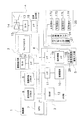
図1は、本発明の一実施形態によるゲーム装置の基本構成を示している。ここでは、ビデオゲーム装置の一例として、家庭用ビデオゲーム装置をとりあげて説明を行うこととする。家庭用ビデオゲーム装置は、家庭用ゲーム機本体および家庭用テレビジョンを備える。家庭用ゲーム機本体には、記録媒体10が装填可能となっており、記録媒体10からゲームデータが適宜読み出されてゲームが実行される。このようにして実行されるゲーム内容が家庭用テレビジョンに表示される。
[Configuration and operation of game device]
FIG. 1 shows a basic configuration of a game device according to an embodiment of the present invention. Here, a home video game device will be described as an example of the video game device. The home video game apparatus includes a home game machine body and a home television. The home game machine body can be loaded with a
家庭用ビデオゲーム装置のゲームシステムは、制御部1と、記憶部2と、画像表示部3と、音声出力部4と、操作入力部5と、コントローラ25とからなっており、それぞれがバス6を介して接続される。このバス6は、アドレスバス、データバス、およびコントロールバスなどを含んでいる。ここで、制御部1、記憶部2、音声出力部4、操作入力部5は、家庭用ビデオゲーム装置の家庭用ゲーム機本体に含まれており、画像表示部3は家庭用テレビジョンに含まれている。
The game system of the home video game apparatus includes a
制御部1は、主に、ゲームプログラムに基づいてゲーム全体の進行を制御するために設けられている。制御部1は、たとえば、CPU(Central Processing Unit)7と、信号処理プロセッサ8と、画像処理プロセッサ9とから構成されている。CPU7と信号処理プロセッサ8と画像処理プロセッサ9とは、それぞれがバス6を介して互いに接続されている。CPU7は、ゲームプログラムからの命令を解釈し、各種のデータ処理や制御を行う。たとえば、CPU7は、信号処理プロセッサ8に対して、画像データを画像処理プロセッサに供給するように命令する。信号処理プロセッサ8は、主に、3次元空間上における計算と、3次元空間上から擬似3次元空間上への位置変換計算と、光源計算処理と、画像および音声データの生成加工処理とを行っている。画像処理プロセッサ9は、主に、信号処理プロセッサ8の計算結果および処理結果に基づいて、描画すべき画像データをRAM12に書き込む処理を行っている。
The
記憶部2は、主に、プログラムデータや、プログラムデータで使用される各種データなどを格納しておくために設けられている。記憶部2は、たとえば、記録媒体10と、インターフェース回路11と、RAM(Random Access Memory)12とから構成されている。記録媒体10には、インターフェース回路11が接続されている。そして、インターフェース回路11とRAM12とはバス6を介して接続されている。記録媒体10は、オペレーションシステムのプログラムデータや、画像データ、音声データ並びに各種プログラムデータからなるゲームデータなどを記録するためのものである。この記録媒体10は、たとえば、ROM(Read Only Memory)カセット、光ディスク、およびフレキシブルディスクなどであり、オペレーティングシステムのプログラムデータやゲームデータなどが記憶される。なお、記録媒体10にはカード型メモリも含まれており、このカード型メモリは、主に、ゲームを中断するときに中断時点での各種ゲームパラメータを保存するために用いられる。RAM12は、記録媒体10から読み出された各種データを一時的に格納したり、制御部1からの処理結果を一時的に記録したりするために用いられる。このRAM12には、各種データとともに、各種データの記憶位置を示すアドレスデータが格納されており、任意のアドレスを指定して読み書きすることが可能になっている。
The
画像表示部3は、主に、画像処理プロセッサ9によってRAM12に書き込まれた画像データや、記録媒体10から読み出される画像データなどを画像として出力するために設けられている。この画像表示部3は、たとえば、テレビジョンモニタ20と、インターフェース回路21と、D/Aコンバータ(Digital-To-Analogコンバータ)22とから構成されている。テレビジョンモニタ20にはD/Aコンバータ22が接続されており、D/Aコンバータ22にはインターフェース回路21が接続されている。そして、インターフェース回路21にバス6が接続されている。ここでは、画像データが、インターフェース回路21を介してD/Aコンバータ22に供給され、ここでアナログ画像信号に変換される。そして、アナログ画像信号がテレビジョンモニタ20に画像として出力される。
The
ここで、画像データには、たとえば、ポリゴンデータやテクスチャデータなどがある。ポリゴンデータはポリゴンを構成する頂点の座標データのことである。テクスチャデータは、ポリゴンにテクスチャを設定するためのものであり、テクスチャ指示データとテクスチャカラーデータとからなっている。テクスチャ指示データはポリゴンとテクスチャとを対応づけるためのデータであり、テクスチャカラーデータはテクスチャの色を指定するためのデータである。ここで、ポリゴンデータとテクスチャデータとには、各データの記憶位置を示すポリゴンアドレスデータとテクスチャアドレスデータとが対応づけられている。このような画像データでは、信号処理プロセッサ8により、ポリゴンアドレスデータの示す3次元空間上のポリゴンデータ(3次元ポリゴンデータ)が、画面自体(視点)の移動量データおよび回転量データに基づいて座標変換および透視投影変換されて、2次元空間上のポリゴンデータ(2次元ポリゴンデータ)に置換される。そして、複数の2次元ポリゴンデータでポリゴン外形を構成して、ポリゴンの内部領域にテクスチャアドレスデータが示すテクスチャデータを書き込む。このようにして、各ポリゴンにテクスチャが貼り付けられた物体つまり各種キャラクタを表現することができる。
Here, the image data includes, for example, polygon data and texture data. Polygon data is coordinate data of vertices constituting a polygon. The texture data is for setting a texture on the polygon, and is composed of texture instruction data and texture color data. The texture instruction data is data for associating polygons and textures, and the texture color data is data for designating the texture color. Here, the polygon data and the texture data are associated with the polygon address data indicating the storage position of each data and the texture address data. In such image data, the
音声出力部4は、主に、記録媒体10から読み出される音声データを音声として出力するために設けられている。音声出力部4は、たとえば、スピーカー13と、増幅回路14と、D/Aコンバータ15と、インターフェース回路16とから構成されている。スピーカー13には増幅回路14が接続されており、増幅回路14にはD/Aコンバータ15が接続されており、D/Aコンバータ15にはインターフェース回路16が接続されている。そして、インターフェース回路16にバス6が接続されている。ここでは、音声データが、インターフェース回路16を介してD/Aコンバータ15に供給され、ここでアナログ音声信号に変換される。このアナログ音声信号が増幅回路14によって増幅され、スピーカー13から音声として出力される。音声データには、たとえば、ADPCM(Adaptive Differential Pulse Code Modulation)データやPCM(Pulse Code Modulation)データなどがある。ADPCMデータの場合、上述と同様の処理方法で音声をスピーカー13から出力することができる。PCMデータの場合、RAM12においてPCMデータをADPCMデータに変換しておくことで、上述と同様の処理方法で音声をスピーカー13から出力することができる。
The
操作入力部5は、主に、操作情報インターフェース回路18と、インターフェース回路19と、ポインティング信号受信部29から構成されている。操作情報インターフェース回路18には、コントローラ25が接続されており、操作情報インターフェース回路18にはインターフェース回路19が接続されている。ポインティング信号受信部29は、後述するポインティング装置27からの信号を受信するためのものである。このポインティング信号受信部29には、インターフェース回路19が接続されている。そして、インターフェース回路19にバス6が接続されている。
The
コントローラ25は、プレイヤが種々の操作命令を入力するために使用する操作装置であり、プレイヤの操作に応じて操作信号をCPU7に送出する。また、コントローラ25には、ポインティング装置27が内蔵されている。
The
加速度センサ24には、たとえば、ピエゾ抵抗型、静電容量型、および磁気センサ型等がある。このような加速度センサ24は、コントローラ25が移動したときに、コントローラ25の移動に応じて加速度の大きさが測定され出力される。ここで用いられている加速度センサ24は、3軸加速度センサであり、コントローラ25の移動に応じて3軸方向の加速度の大きさが測定され出力される。すなわち、コントローラ25が移動すると、加速度センサ24から3軸方向の加速度の大きさが加速度データとして、コントローラ25から操作入力部5へと出力される。この加速度データを制御部1に認識・処理させることにより、3次元空間におけるコントローラ25の動きを制御部1に認識させることができる。
Examples of the
ポインティング装置27は、コントローラの先端に内蔵されている。このポインティング装置27をポインティング信号受信部29側に向けながらコントローラ25を移動させると、テレビジョンモニタ20に表示されたオブジェクトを移動させることができる。すなわち、ポインティング装置27から出力された初期信号がポインティング信号受信部29に入力されると、ポインティング装置27の対象オブジェクトの位置座標が制御部1に認識される。そして、コントローラ25を移動させると、ポインティング装置27からの第2信号がポインティング信号受信部29に入力され、コントローラ25の移動量に対応する対象オブジェクトの位置座標からの移動量が制御部1により算出される。そして、この対象オブジェクトの移動量に応じて、オブジェクトが制御部1からの命令によってテレビジョンモニタ20おいて移動させられる。
The
また、コントローラ25には、たとえば、上方向キー17U、下方向キー17D、左方向キー17L、右方向キー17Rからなる十字方向キーが設けられている。上方向キー17U、下方向キー17D、左方向キー17L及び右方向キー17Rでは、例えば、キャラクタ、オブジェクト、およびカーソルをテレビジョンモニタ20の画面上で上下左右に移動させることができる。上方向キー17U、下方向キー17D、左方向キー17L及び右方向キー17Rが操作されると、各キーに対応する操作信号がコントローラ25から操作入力部5へと出力され、この操作信号に対応したコマンドが制御部1に認識される。
Further, the
なお、コントローラ25の各ボタン及び各キーは、外部からの押圧力によって中立位置から押圧されるとオンになり、押圧力が解除されると中立位置に復帰してオフになるオンオフスイッチになっている。
Each button and each key of the
以上のような構成からなる家庭用ビデオゲーム装置の概略動作を、以下に説明する。電源スイッチ(図示省略)がオンにされゲームシステム1に電源が投入されると、CPU7が、記録媒体10に記憶されているオペレーティングシステムに基づいて、記録媒体10から画像データ、音声データ、およびプログラムデータを読み出す。読み出された画像データ、音声データ、およびプログラムデータの一部若しくは全部は、RAM12に格納される。そして、CPU7が、RAM12に格納されたプログラムデータに基づいて、RAM12に格納された画像データや音声データにコマンドを発行する。
The schematic operation of the home video game apparatus having the above configuration will be described below. When a power switch (not shown) is turned on and the
画像データの場合、CPU7からのコマンドに基づいて、まず、信号処理プロセッサ8が、3次元空間上におけるキャラクタの位置計算および光源計算などを行う。次に、画像処理プロセッサ9が、信号処理プロセッサ8の計算結果に基づいて、描画すべき画像データのRAM12への書き込み処理などを行う。そして、RAM12に書き込まれた画像データが、インターフェース回路13を介してD/Aコンバータ17に供給される。ここで、画像データがD/Aコンバータ17でアナログ映像信号に変換される。そして、画像データはテレビジョンモニタ20に供給され画像として表示される。
In the case of image data, based on a command from the
音声データの場合、まず、信号処理プロセッサ8が、CPU7からのコマンドに基づいて音声データの生成および加工処理を行う。ここでは、音声データに対して、たとえば、ピッチの変換、ノイズの付加、エンベロープの設定、レベルの設定及びリバーブの付加などの処理が施される。次に、音声データは、信号処理プロセッサ8から出力されて、インターフェース回路16を介してD/Aコンバータ15に供給される。ここで、音声データがアナログ音声信号に変換される。そして、音声データは増幅回路14を介してスピーカー13から音声として出力される。
In the case of audio data, first, the
〔ゲーム装置における各種処理概要〕
本ゲーム機1において実行されるゲームは、たとえば野球ゲームである。本ゲーム機1は、画像表示部3のテレビジョンモニタ20に移動体を表示し、加速度センサ24が内蔵されたコントローラ25が移動したときに加速度センサ24が検知した加速度データに基づいて移動体の移動状態を制御するビデオゲームを実現可能になっている。図2は、本発明で主要な役割を果たす機能を説明するための機能ブロック図である。
[Outline of various processes in game devices]
The game executed on the
オブジェクト表示手段50は、オブジェクトに対応する画像データを用いてオブジェクトを画像表示部3のテレビジョンモニタ20に表示する機能を備えている。オブジェクト表示手段50では、オブジェクトに対応する画像データを用いてオブジェクトが画像表示部3のテレビジョンモニタ20に表示される。
The object display means 50 has a function of displaying an object on the
移動状態データ認識手段51は、移動体の移動状態を規定するための移動状態データを制御部1に認識させる機能を備えている。移動状態データ認識手段51では、移動体の移動状態を規定するための移動状態データが制御部1により認識される。
The movement state
加速度データ認識手段52は、コントローラから入力部に連続的に入力される加速度データを制御部1に認識させる機能を備えている。加速度データ認識手段52では、コントローラから入力部に連続的に入力される加速度データが制御部1により認識される。詳細には、加速度データ認識手段52では、制御部1に認識された加速度データの値が所定の値以上であるか否かを制御部1に判断させ、制御部1に認識された加速度データの値が所定の値以上であると制御部1に判断された場合に、加速度データが制御部1により認識される。この場合、制御部1に認識された加速度データが所定の値以上であると制御部1により判断された場合に、加速度データが制御部1により認識されるようになっているので、プレイヤがコントローラを微妙に移動させてしまったとしても、コントローラの移動に連動してオブジェクトたとえば投手キャラクタが投球動作を開始することがないようにすることができる。すなわち、プレイヤが思わずコントローラを移動させてしまったときの誤操作を防止することができる。
The acceleration
時間間隔データ認識手段53は、コントローラから入力部に連続的に入力される加速度データの時間間隔を時間間隔データとして制御部1に認識させる機能を備えている。時間間隔データ認識手段53では、コントローラから入力部に連続的に入力される加速度データの時間間隔が時間間隔データとして制御部1により認識される。
The time interval
時間経過判断手段54は、制御部1に認識された加速度データの認識開始時間を基準として所定の時間が経過したか否かを制御部1に判断させる機能を備えている。時間経過判断手段54では、制御部1に認識された加速度データの認識開始時間を基準として所定の時間が経過したか否かが制御部1により判断される。
The time elapse determination means 54 has a function of causing the
位置データ算出手段55は、制御部1に認識された加速度データおよび時間間隔データに基づいて、コントローラの位置データを制御部1に算出させる機能を備えている。位置データ算出手段55では、制御部1に認識された加速度データおよび時間間隔データに基づいて、コントローラの位置データが制御部1により算出される。詳細には、位置データ算出手段55では、制御部1に認識された加速度データの認識開始時間を基準として所定の時間が経過したと制御部1により判断された場合に、所定の時間内において制御部1に認識された加速度データおよび時間間隔データに基づいて、コントローラの位置データが制御部1により算出される。より詳細には、位置データ算出手段55では、制御部1に認識された加速度データの認識開始時間を基準として所定の時間が経過したと制御部1により判断された場合に、所定の時間内において制御部1に認識された加速度データを時間間隔データを用いて制御部1に積分計算させることにより、コントローラ25の速度の大きさデータが制御部1により算出される。そして、速度の大きさデータを時間間隔データを用いて制御部1に積分計算させることにより、コントローラ25の位置データが制御部1により算出される。
The position
移動量算出手段56は、コントローラの位置データに基づいて、コントローラの変化量を制御部1に算出させる機能を備えている。移動量算出手段56では、コントローラの位置データに基づいて、コントローラの変化量が制御部1により算出される。詳細には、位置データ算出手段55において所定の時間内で算出された位置データの初期位置座標および最終位置座標に基づいて、コントローラの垂直方向および水平方向の移動量が制御部1により算出される。ここでは、コントローラ25を移動させる空間である3次元実空間における位置データの最終位置座標と初期位置座標との差をとることにより、コントローラの垂直方向および水平方向の移動量が制御部1により算出される。
The movement
移動状態データ修正手段57は、コントローラの変化量に応じて移動状態データを制御部1に修正させる機能を備えている。移動状態データ修正手段57では、コントローラの変化量に応じて移動状態データが制御部1により修正される。詳細には、移動状態データ修正手段57では、コントローラの垂直方向の移動量に応じて、移動体の移動速度を規定する移動速度データが制御部1により修正される。また、移動状態データ修正手段57では、コントローラの水平方向の移動量に応じて、移動体の変化量を規定する変化量データが制御部1により修正される。
The movement state data correction means 57 has a function of causing the
移動体表示手段58は、移動状態データに基づいて、移動体を移動体に対応する画像データを用いて画像表示部3のテレビジョンモニタ20に表示する機能を備えている。移動体表示手段58では、移動状態データに基づいて、移動体が移動する状態が、移動体に対応する画像データを用いて画像表示部3のテレビジョンモニタ20に連続的に表示される。
The moving body display means 58 has a function of displaying the moving body on the
〔野球ゲームにおける投球されたボールの制御システムの概要と各種処理フロー〕
ここでは、野球ゲームにおける投球されたボールの制御システムについて説明する。また、図8に示した投球されたボールの制御システムのフローについても同時に説明する。
[Outline of the control system of the pitched ball in the baseball game and various processing flows]
Here, a control system for a pitched ball in a baseball game will be described. The flow of the pitched ball control system shown in FIG. 8 will also be described at the same time.
本野球ゲームにおいて、プレイヤが投手キャラクタを操作する場合、図3に示すように、投手キャラクタ71と、打者キャラクタ72と、捕手キャラクタ73とが、テレビジョンモニタ20に表示される(S1)。なお、ここでは、投手キャラクタ71が右投手である場合を例に説明を行う。
In the baseball game, when the player operates the pitcher character, as shown in FIG. 3, a
まず、コントローラ25を上下左右に移動させると、コントローラ25のポインティング装置27から出力された信号がポインティング信号受信部29に入力され、コントローラ25の移動量が制御部1に認識される。すると、コントローラ25の移動量に応じて捕手キャラクタ73のミット位置が制御部1により移動させられ、捕手キャラクタ73のミット位置に対応する座標が制御部1により認識される(S2)。すなわち、プレイヤは、コントローラ25を移動させることにより、投球コースを制御部1に認識させることができる。なお、捕手キャラクタ73はテレビジョンモニタ20の上部に表示されているが、ここに示したミット位置に対応する投球コースの座標は、ミット位置の移動に連動して、ゲーム空間におけるホームベース手前側の所定位置(所定のx座標位置)のyz平面において移動するようになっている。
First, when the
続いて、十字方向キーが操作されると、十字方向キーの各キー17U,17D,17L,17Rに割り当てられた球種に対応する初期の移動状態データが制御部1に認識される(S3)。この移動状態データはボールキャラクタ74の移動速度を規定する移動速度データおよびボールキャラクタ74の変化量を規定する変化量データからなっており、これら移動速度データおよび変化量データはゲームプログラムにおいて予め規定されている。なお、ここでは、上方向キー17Uにはストレート、下方向キー17Dにはフォーク、右方向キー17Rにはシュート、左方向キー17Lにはカーブが割り当てられており、プレイヤが十字方向キーを押すと、各キー17U,17D,17L,17Rに割り当てられた球種に対応する初期の移動状態データが制御部1に認識される。
Subsequently, when the cross direction key is operated, initial movement state data corresponding to the ball type assigned to each of the
次に、図4に示すように、投手がスローイングするようにコントローラを移動させると、コントローラ25に内蔵された加速度センサ24が検知した加速度データGが、コントローラ25から操作入力部5に連続的に出力され操作入力部5に入力される(S4)。すると、操作入力部5に入力された加速度データGの絶対値が所定の値以上であるか否かが制御部1により判断される(S5)。そして、加速度データGの絶対値が所定の値以上であると制御部1に判断された場合(S5でYes)、最初の加速度データが制御部1に認識される(S6)。このときに、加速度データの認識開始時間が制御部1に認識される(S7)。すると、投手キャラクタ71に投球動作を開始させるためのコマンドが、制御部1から発行される(S8)。そして、最初の加速度データに続く加速度データGが制御部1により順次認識される(S9)。また、このときには、操作入力部5に連続的に入力される加速度データGの時間間隔が、時間間隔データdtとして制御部1により認識される(S10)。一方で、操作入力部5に入力された加速度データGの絶対値が所定の値未満であると制御部1に判断された場合(S5でNo)、加速度データGが制御部1により認識されない(S11)。すなわち、投手キャラクタ71に投球動作を開始させるためのコマンドは制御部1から発行されない。
Next, as shown in FIG. 4, when the controller is moved so that the pitcher throws, the acceleration data G detected by the
続いて、最初に制御部1に認識された加速度データの認識開始時間を基準として所定の時間が経過したか否かが制御部1により判断される(S12)。具体的には、投手キャラクタの投球動作が終了するまでの所定の時間が経過したか否かが制御部1により判断される。なお、ここに示した所定の時間は、投手キャラクタが投球動作を開始してから投手キャラクタがボールをリリースするまでの時間に対応している。この所定の時間は、ゲームプログラムにおいて予め規定されている。
Subsequently, the
そして、認識開始時間を基準として所定の時間が経過したと制御部1により判断された場合に(S12でYes)、図5に示すように、所定の時間内において制御部1に認識された加速度データGが時間間隔データdtを用いて制御部1により積分計算され、コントローラ25の速度の大きさデータVが制御部1により算出される(S13)。また、このコントローラ25の速度の大きさデータVが時間間隔データdtを用いて制御部1により積分計算され、コントローラ25の位置データXが制御部1により算出される(S14)。
Then, when the
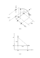
続いて、所定の時間内で算出されたコントローラ25の位置データXの初期位置座標および最終位置座標に基づいて、コントローラの垂直方向および水平方向の移動量が制御部1により算出される(S15)。具体的には、認識開始時間におけるコントローラ25の初期位置座標のz座標値から、認識開始時間から所定の時間が経過したときの時間におけるコントローラ25の最終位置座標のz座標値を減算する計算を制御部1に実行させることにより、コントローラの垂直方向の移動量が制御部1により算出される。また、認識開始時間から所定の時間が経過したときの時間におけるコントローラ25の最終位置座標のy座標値から、認識開始時間におけるコントローラ25の初期位置座標のy座標値を減算する計算を制御部1に実行させることにより、コントローラの水平方向の移動量が制御部1により算出される(図6を参照)。
Subsequently, based on the initial position coordinates and the final position coordinates of the position data X of the
すると、コントローラの垂直方向の移動量に応じて、ボールキャラクタ74の移動速度を規定する移動速度データが制御部1により修正される(S16)。そして、コントローラの水平方向の移動量に応じて、ボールキャラクタ74の変化球の変化量を規定する変化量データが制御部1により修正される(S17)。すると、修正された変化球の変化量データにより規定される変化量を、移動するボールキャラクタ74がテレビジョンモニタ20に表示されている間のフレーム数で除算する計算が、制御部1により実行され、単位フレームあたりの変化球の変化量が制御部1により算出される。そして、移動するボールキャラクタ74がテレビジョンモニタ20に表示される表示時間をフレーム数で除算する計算が制御部1により実行され、単位フレームあたりの表示時間が制御部1により算出される。なお、移動するボールキャラクタ74がテレビジョンモニタ20に表示される表示時間は、球種ごとにゲームプログラムにおいて予め設定されている。
Then, according to the amount of movement of the controller in the vertical direction, the movement speed data defining the movement speed of the
すると、修正された移動速度データおよび変化量データからなる移動状態データに基づいてボールキャラクタ74が移動する状態が、ボールに対応する画像データを用いて画像表示部3のテレビジョンモニタ20に連続的に表示される(S19)。具体的には、ボールに対応する画像データたとえば2次元画像データ又はポリゴンデータを、単位フレームあたりの表示時間表示した後に、単位フレームあたりの変化量ずつ変化球が変化する方向に移動させる。このようにして、投手キャラクタからリリースされたボールキャラクタ74が修正された変化量で捕手キャラクタへと移動する状態が、画像表示部3のテレビジョンモニタ20に表示される。なお、十字方向キーの上方向キー17Uが押されて球種としてストレートが指示された場合は、上記のボールキャラクタ74の変化量データは修正されず、移動速度データのみが修正され、修正された移動速度データに基づいて、ボールキャラクタ74が移動する状態が、ボールに対応する画像データを用いて画像表示部3のテレビジョンモニタ20に連続的に表示される。
Then, the state in which the
〔野球ゲームにおける投球されたボールの制御システムの各手段に対する処理内容および補足説明〕
・位置データ算出手段
3軸方向の加速度の大きさからなる加速度データGが制御部1により認識され、コントローラ25から操作入力部5に連続的に入力される加速度データG(gx,gy,gz,t)の時間間隔が時間間隔データdtとして制御部1により認識されると、図5に示すように、コントローラ25から操作入力部5に連続的に入力された加速度データGが時間間隔データdtを用いて制御部1により積分計算され、コントローラ25の3軸方向の速度の大きさデータV(vx,vy,vz,t)が制御部1により算出される。たとえば、まず時刻t1に制御部1に加速度データG1(gx1,gy1,gz1,t1)が認識され、次に時刻t2に制御部1に加速度データG2(gx2,gy2,gz2,t2)が認識された場合、∫[G2(gx2,gy2,gz2,t2)−G1(gx1,gy1,gz1,t1)]・dtという計算を時刻t2と時刻t1の間で制御部1に実行させることにより、コントローラ25の速度の大きさデータV1(vx1,vy1,vz1,t1)が制御部1により算出される。同様に、時刻t2に続く時刻t3に制御部1に加速度データG3(gx3,gy3,gz3,t3)が認識された場合、∫[G3(gx3,gy3,gz3,t3)−G2(gx2,gy2,gz2,t2)]・dtという計算を時刻t3と時刻t2との間で制御部1に実行させることにより、コントローラ25の速度の大きさデータV2(vx2,vy2,vz2,t2)が制御部1により算出される。また、時刻t3に続く時刻t4に制御部1に加速度データG4(gx4,gy4,gz4,t4)が認識された場合、∫[G4(gx4,gy4,gz4,t4)−G3(gx3,gy3,gz3,t3)]・dtという計算を時刻t4と時刻t3の間で制御部1に実行させることにより、コントローラ25の速度の大きさデータV3(vx3,vy3,vz3,t3)が制御部1により算出される。
[Processing contents and supplementary explanation for each means of the control system of the pitched ball in the baseball game]
Position data calculation means Acceleration data G consisting of the magnitude of acceleration in the three-axis directions is recognized by the
このように算出されたコントローラ25の速度の大きさデータVが時間間隔データdtを用いて制御部1によりさらに積分計算されると、コントローラ25の位置データXが制御部1により算出される。たとえば、∫[V2(vx2,vy2,vz2,t2)−V1(vx1,vy1,vz1,t1)]・dtという計算を時刻t2と時刻t1との間で制御部1に実行させることにより、コントローラ25の位置データX1(x1,y1,z1,t1)が制御部1により算出される。同様に、∫[V3(vx3,vy3,vz3,t3)−V2(vx2,vy2,vz2,t2)]・dtという計算を時刻t3と時刻t2との間で制御部1に実行させることにより、コントローラ25の位置データX2(x2,y2,z2,t2)が制御部1により算出される。
When the speed magnitude data V of the
コントローラ25の加速度データGが制御部1に認識されたときに、上記のような一連の計算を制御部1に実行させることにより、コントローラ25の加速度データGに基づいて、各時刻のコントローラ25の速度の大きさデータおよび位置データを算出することができる。
When the
なお、上記のコントローラ25の速度の大きさデータVおよび位置データXを算出するにあたり、コントローラ25の加速度データGが制御部1に最初に認識された時間tsが、認識開始時間となる。また、認識開始時間から所定の時間が経過したときの時間teが、認識終了時刻となる。
・移動状態データ修正手段
図6に示すように、プレイヤがコントローラを右手に持って投手のようにスローイングを行うと、コントローラ25の初期位置座標As(xs,ys,zs,ts)およびコントローラ25の最終位置座標Ae(xe,ye,ze,te)が、位置データ算出手段において制御部1により算出される。これら初期位置座標Asと最終位置座標Aeとに基づいて、初期位置座標Asと最終位置座標Aeとの差をとることにより、コントローラ25の移動量Lc(|As−Ae|=(|xs−xe|,|ys−ye|,|zs−ze|))が制御部1により算出される。このようにして、コントローラ25の垂直方向の移動量Lcz(=zs−ze))およびコントローラ25の水平方向の移動量Lcy(=ye−ys)が制御部1により算出されると、コントローラの垂直方向の移動量Lczおよび水平方向の移動量Lcyに応じて、ボールキャラクタ74の移動速度を規定する移動速度データおよびボールキャラクタ74の変化量を規定する変化量データが制御部1により修正される。
In calculating the speed magnitude data V and the position data X of the
-Movement state data correction means As shown in FIG. 6, when the player throws the controller in the right hand and throws like a pitcher, the initial position coordinates As (xs, ys, zs, ts) of the
たとえば、ボールキャラクタ74の移動速度が5段階(1〜5)で変化するようになっている場合、図7に示すような対応テーブルに基づいて、ボールキャラクタ74の移動速度を規定する移動速度データが制御部1により修正される。具体的には、コントローラ25の垂直方向の移動量Lczが1cm〜30cmの範囲にあると制御部1により判断された場合は段階1に対応するボールキャラクタ74の移動速度が制御部1により選択され、垂直方向の移動量Lczが30cm〜40cmの範囲にあると制御部1により判断された場合は段階2に対応する移動速度が制御部1により選択され、垂直方向の移動量Lczが40cm〜50cmの範囲にあると制御部1により判断された場合は段階3に対応する移動速度が制御部1により選択される。また、コントローラ25の垂直方向の移動量Lczが50cm〜60cmの範囲にあると制御部1により判断された場合は段階4に対応するボールキャラクタ74の移動速度が制御部1により選択され、垂直方向の移動量Lczが60cm以上であると制御部1により判断された場合は段階5に対応するボールキャラクタ74の移動速度が制御部1により選択される。ここでは、段階1に対応するボールキャラクタ74の移動速度が最低移動速度に対応しており、段階5に対応するボールキャラクタ74の移動速度が最大移動速度に対応している。これら最低移動速度および最大移動速度を規定する移動速度データは、各球種ごとにゲームプログラムにおいて予め規定されている。
For example, when the moving speed of the
たとえば、ボールキャラクタ74の変化球の変化量が5段階(1〜5)で変化するようになっている場合、図7に示すような対応テーブルに基づいて、ボールキャラクタ74の移動量を規定する移動量データが制御部1により修正される。具体的には、コントローラ25の水平方向の移動量Lcyが1cm〜20cmの範囲にあると制御部1により判断された場合は段階1に対応するボールキャラクタ74の移動量が制御部1により選択され、水平方向の移動量Lcyが20cm〜30cmの範囲にあると制御部1により判断された場合は段階2に対応する移動量が制御部1により選択され、水平方向の移動量Lcyが30cm〜40cmの範囲にあると制御部1により判断された場合は段階3に対応する移動量が制御部1により選択される。また、コントローラ25の水平方向の移動量Lcyが40cm〜50cmの範囲にあると制御部1により判断された場合は段階4に対応するボールキャラクタ74の移動量が制御部1により選択され、水平方向の移動量Lcyが50cm以上であると制御部1により判断された場合は段階5に対応するボールキャラクタ74の移動量が制御部1により選択される。ここでは、段階1に対応するボールキャラクタ74の移動量が最低移動量に対応しており、段階5に対応するボールキャラクタ74の移動量が最大移動量に対応している。これら最低移動量および最大移動量を規定する移動量データは、各球種ごとにゲームプログラムにおいて予め規定されている。
For example, when the change amount of the changing sphere of the
上記のことから、コントローラ25の垂直方向の移動量が大きくなればなるほど、ボールキャラクタ74の移動速度を大きくすることができ、コントローラ25の水平方向の移動量が大きくなればなるほど、変化球の変化量を大きくすることができる。
From the above, the movement speed of the
なお、ここでは、コントローラの垂直方向の移動量Lczとボールキャラクタ74の移動速度の段階との対応関係に基づいて、ボールキャラクタ74の移動速度の段階に対応する移動速度が制御部1により選択される場合の例を示したが、コントローラの垂直方向の移動量Lczとボールキャラクタ74の移動速度との対応を示す対応テーブルを作成しておき、コントローラの垂直方向の移動量Lczからボールキャラクタ74の移動速度を直接的に求められるようにしても良い。また、コントローラの水平方向の移動量Lcyとボールキャラクタ74の変化球の移動量の段階との対応関係に基づいて、ボールキャラクタ74の移動量の段階に対応する変化球の移動量が制御部1により選択される場合の例を示したが、コントローラの水平方向の移動量Lcyとボールキャラクタ74の移動量との対応を示す対応テーブルを作成しておき、コントローラの水平方向の移動量Lcyからボールキャラクタ74の変化球の移動量を直接的に求められるようにしても良い。
Here, based on the correspondence between the movement amount Lcz in the vertical direction of the controller and the stage of the moving speed of the
〔他の実施形態〕
(a) 前記実施形態では、コントローラ25の位置データに基づいてボールキャラクタ74の移動量が算出される場合の例を示したが、ボールキャラクタ74の移動量はコントローラ25の角度データに基づいて算出されるようにしても良い。たとえば、図9に示すように、プレイヤがコントローラ25を右手に持って投手のようにスローイングを行ったときに、コントローラ25から出力される加速度データたとえばx’軸まわりの角加速度データに基づいて、コントローラの回転角度を制御部1に算出させるようにしても良い。この場合は、図5に示した関係を角加速度に適用することにより、x’軸まわりの角加速度データが制御部1により積分計算され、x’軸まわりの角速度データが制御部1により算出される。そして、この角速度データが制御部により再度積分計算され、x’軸まわりの回転角度を規定する角度データが制御部1により算出される。そして、たとえばボールキャラクタ74の変化量が5段階(1〜5)で変化するようになっている場合には、図7に示すような対応テーブルに基づいて、x’軸まわりの角度に応じた各段階が制御部1に認識され、各段階に対応するボールキャラクタ74の変化量が制御部1により認識される。なお、各段階に対応するボールキャラクタ74の変化量は、ゲームプログラムにより予め規定されている。そして、この認識されたボールキャラクタ74の変化量に対応する変化量データに基づいて、ボールキャラクタ74が移動する状態がボールキャラクタ74に対応する画像データを用いて画像表示部3のテレビジョンモニタ20に表示される。なお、この場合のボールキャラクタ74の移動速度は、前記実施形態と同様の方法で制御部1により算出される。
[Other Embodiments]
(A) In the above embodiment, an example in which the movement amount of the
(b) 前記実施形態では、ゲームプログラムを適用しうるコンピュータの一例としての家庭用ビデオゲーム装置を用いた場合の例を示したが、ゲーム装置は、前記実施形態に限定されず、モニタが別体に構成されたゲーム装置、モニタが一体に構成されたゲーム装置、ゲームプログラムを実行することによってゲーム装置として機能するパーソナルコンピュータやワークステーションなどにも同様に適用することができる。 (B) In the above-described embodiment, an example in which a home video game apparatus as an example of a computer to which a game program can be applied is used is shown. However, the game apparatus is not limited to the above-described embodiment, and a monitor is separately provided. The present invention can be similarly applied to a game device configured in a body, a game device in which a monitor is integrated, a personal computer functioning as a game device by executing a game program, a workstation, and the like.
(c) 本発明には、前述したようなゲームを実行するプログラムおよびこのプログラムを記録したコンピュータ読み取り可能な記録媒体も含まれる。この記録媒体としては、カートリッジ以外に、たとえば、コンピュータ読み取り可能なフレキシブルディスク、半導体メモリ、CD−ROM、DVD、MO、ROMカセット、その他のものが挙げられる。 (C) The present invention includes a program for executing the above-described game and a computer-readable recording medium on which the program is recorded. Examples of the recording medium include a computer-readable flexible disk, a semiconductor memory, a CD-ROM, a DVD, an MO, a ROM cassette, and the like in addition to the cartridge.
1 制御部
5 操作入力部
20 テレビジョンモニタ
24 加速度センサ
25 コントローラ
27 ポインティング装置
29 ポインティング信号受信部
50 オブジェクト表示手段
51 移動状態データ認識手段
52 加速度データ認識手段
53 時間間隔データ認識手段
54 時間経過判断手段
55 位置データ算出手段
56 移動量算出手段
57 移動状態データ修正手段
58 移動体表示手段
71 投手キャラクタ
72 打者キャラクタ
74 ボールキャラクタ
dt 時間間隔
G コントローラの加速度データ
V コントローラの速度の大きさデータ
X コントローラの位置データ
As コントローラの初期位置座標
Ae コントローラの最終位置座標
Lc コントローラの移動量
Lcy コントローラの水平方向の移動量
Lcz コントローラの垂直方向の移動量
DESCRIPTION OF
Claims (4)
記憶部に格納される、移動体の移動速度を規定する移動速度データおよび移動体の位置の変化量を規定する変化量データを、制御部に認識させる移動状態データ認識機能と、
前記コントローラから連続的に出力される前記加速度データを制御部に認識させる加速度データ認識機能と、
前記コントローラから連続的に出力される前記加速度データの時間間隔を時間間隔データとして制御部に認識させる時間間隔データ認識機能と、
制御部に認識された前記加速度データおよび前記時間間隔データに基づいて、前記コントローラの位置データを制御部に算出させる位置データ算出機能と、
前記コントローラの位置データに基づいて、前記コントローラの垂直方向の移動量および前記コントローラの垂直方向に直交する方向の移動量を、制御部に算出させる変化量算出機能と、
前記コントローラの垂直方向の移動量に応じて前記移動速度データを所定の範囲内で制御部に修正させ、前記コントローラの垂直方向に直交する方向の移動量に応じて前記変化量データを所定の範囲内で制御部に修正させる移動状態データ修正機能と、
修正された前記移動速度データおよび修正された前記変化量データに基づいて、前記移動体が移動する状態を前記移動体に対応する画像データを用いて前記画像表示部に表示する移動体表示機能と、
を実現させるためのビデオゲームプログラム。 A computer capable of displaying a moving object on an image display unit and realizing a video game for controlling a moving state of the moving object based on acceleration data detected by the acceleration sensor when a controller incorporating the acceleration sensor moves.
A movement state data recognition function for causing the control unit to recognize movement speed data defining the movement speed of the moving body and change amount data defining the amount of change in the position of the moving body, which are stored in the storage unit;
An acceleration data recognition function for causing the control unit to recognize the acceleration data continuously output from the controller;
A time interval data recognition function for causing the control unit to recognize the time interval of the acceleration data continuously output from the controller as time interval data;
A position data calculation function for causing the control unit to calculate position data of the controller based on the acceleration data and the time interval data recognized by the control unit;
Based on the controller position data, a change amount calculation function for causing the control unit to calculate a movement amount in the vertical direction of the controller and a movement amount in the direction perpendicular to the vertical direction of the controller ;
The moving speed data is corrected by a control unit within a predetermined range according to the vertical movement amount of the controller, and the change amount data is set within a predetermined range according to the movement amount of the controller in the direction orthogonal to the vertical direction. Movement state data correction function to be corrected by the control unit within ,
A moving body display function for displaying a state in which the moving body moves on the image display unit using image data corresponding to the moving body based on the corrected moving speed data and the corrected change amount data ; ,
A video game program for realizing this.
制御部に認識された前記加速度データの認識開始時間を基準として所定の時間が経過したか否かを制御部に判断させる時間経過判断機能、
をさらに実現させ、
前記位置データ算出機能では、前記所定の時間が経過したと制御部により判断された場合に、制御部に認識された前記加速度データおよび前記時間間隔データに基づいて、前記コントローラの位置データおよび角度データの少なくともいずれか一方のデータが制御部により算出される、
請求項1に記載のビデオゲームプログラム。 In the computer,
A time elapse determination function for causing the control unit to determine whether or not a predetermined time has elapsed with reference to the recognition start time of the acceleration data recognized by the control unit;
Further realized,
In the position data calculation function, when the control unit determines that the predetermined time has elapsed, the position data and angle data of the controller are based on the acceleration data and the time interval data recognized by the control unit. At least one of the data is calculated by the control unit,
The video game program according to claim 1 .
記憶部に格納される、移動体の移動速度を規定する移動速度データおよび移動体の位置の変化量を規定する変化量データを、制御部に認識させる移動状態データ認識手段と、
前記コントローラから連続的に出力される前記加速度データを制御部に認識させる加速度データ認識手段と、
前記コントローラから連続的に出力される前記加速度データの時間間隔を時間間隔データとして制御部に認識させる時間間隔データ認識手段と、
制御部に認識された前記加速度データおよび前記時間間隔データに基づいて、前記コントローラの位置データを制御部に算出させる位置データ算出手段と、
前記コントローラの位置データに基づいて、前記コントローラの垂直方向の移動量および前記コントローラの垂直方向に直交する方向の移動量を、制御部に算出させる変化量算出手段と、
前記コントローラの垂直方向の移動量に応じて前記移動速度データを所定の範囲内で制御部に修正させ、前記コントローラの垂直方向に直交する方向の移動量に応じて前記変化量データを所定の範囲内で制御部に修正させる移動状態データ修正手段と、
修正された前記移動速度データおよび修正された前記変化量データに基づいて、前記移動体が移動する状態を前記移動体に対応する画像データを用いて前記画像表示部に表示する移動体表示手段と、
を備えるゲーム装置。 A game device capable of executing a video game that displays a moving object on an image display unit and controls a moving state of the moving object based on acceleration data detected by the acceleration sensor when a controller with a built-in acceleration sensor moves. There,
A moving state data recognizing means for causing the control unit to recognize movement speed data defining the moving speed of the moving body and change amount data defining the amount of change in the position of the moving body, which are stored in the storage unit;
Acceleration data recognition means for causing the control unit to recognize the acceleration data continuously output from the controller;
Time interval data recognition means for causing the control unit to recognize the time interval of the acceleration data continuously output from the controller as time interval data;
Position data calculating means for causing the controller to calculate position data of the controller based on the acceleration data and the time interval data recognized by the controller ;
Based on the position data of the controller, change amount calculation means for causing the control unit to calculate the movement amount in the vertical direction of the controller and the movement amount in the direction perpendicular to the vertical direction of the controller ;
The moving speed data is corrected by a control unit within a predetermined range according to the vertical movement amount of the controller, and the change amount data is set within a predetermined range according to the movement amount of the controller in the direction orthogonal to the vertical direction. Moving state data correction means to be corrected by the control unit within ,
Moving body display means for displaying a state in which the moving body moves on the image display unit using image data corresponding to the moving body based on the corrected moving speed data and the corrected amount of change data ; ,
A game device comprising:
記憶部に格納される、移動体の移動速度を規定する移動速度データおよび移動体の位置の変化量を規定する変化量データを、制御部に認識させる移動状態データ認識ステップと、
前記コントローラから連続的に出力される前記加速度データを制御部に認識させる加速度データ認識ステップと、
前記コントローラから連続的に出力される前記加速度データの時間間隔を時間間隔データとして制御部に認識させる時間間隔データ認識ステップと、
制御部に認識された前記加速度データおよび前記時間間隔データに基づいて、前記コントローラの位置データを制御部に算出させる位置データ算出ステップと、
前記コントローラの位置データに基づいて、前記コントローラの垂直方向の移動量および前記コントローラの垂直方向に直交する方向の移動量を、制御部に算出させる変化量算出ステップと、
前記コントローラの垂直方向の移動量に応じて前記移動速度データを所定の範囲内で制御部に修正させ、前記コントローラの垂直方向に直交する方向の移動量に応じて前記変化量データを所定の範囲内で制御部に修正させる移動状態データ修正ステップと、
修正された前記移動速度データおよび修正された前記変化量データに基づいて、前記移動体が移動する状態を前記移動体に対応する画像データを用いて前記画像表示部に表示する移動体表示ステップと、
を備えるゲーム制御方法。 A game control method capable of controlling a video game in which a moving body is displayed on an image display unit and a moving state of the moving body is controlled based on acceleration data detected by the acceleration sensor when a controller incorporating the acceleration sensor moves. Because
A movement state data recognition step for causing the control unit to recognize movement speed data defining the movement speed of the moving body and change amount data defining the amount of change in the position of the moving body, which are stored in the storage unit;
An acceleration data recognition step for causing the control unit to recognize the acceleration data continuously output from the controller;
A time interval data recognition step for causing the control unit to recognize the time interval of the acceleration data continuously output from the controller as time interval data;
A position data calculation step for causing the controller to calculate position data of the controller based on the acceleration data and the time interval data recognized by the controller ;
Based on the position data of the controller, a change amount calculation step for causing the control unit to calculate the movement amount in the vertical direction of the controller and the movement amount in the direction perpendicular to the vertical direction of the controller ;
The moving speed data is corrected by a control unit within a predetermined range according to the vertical movement amount of the controller, and the change amount data is set within a predetermined range according to the movement amount of the controller in the direction orthogonal to the vertical direction. Moving state data correction step to be corrected by the control unit within ,
A moving body display step of displaying, on the image display section, image data corresponding to the moving body based on the corrected moving speed data and the corrected change amount data, using the image data corresponding to the moving body; ,
A game control method comprising:
Priority Applications (5)
| Application Number | Priority Date | Filing Date | Title |
|---|---|---|---|
| JP2005372073A JP4029102B2 (en) | 2005-12-26 | 2005-12-26 | Video game program, video game apparatus, and video game control method |
| KR1020087018171A KR100994409B1 (en) | 2005-12-26 | 2006-10-25 | Computer readable medium on which video game program is recorded, video game machine, and video game control method |
| PCT/JP2006/321232 WO2007074573A1 (en) | 2005-12-26 | 2006-10-25 | Video game program, video game machine, and video game control method |
| TW095141172A TW200727953A (en) | 2005-12-26 | 2006-11-07 | Video game program, video game machine, and video game control method |
| US12/139,946 US20080254898A1 (en) | 2005-12-26 | 2008-06-16 | Video game program, video game device, and video game control method |
Applications Claiming Priority (1)
| Application Number | Priority Date | Filing Date | Title |
|---|---|---|---|
| JP2005372073A JP4029102B2 (en) | 2005-12-26 | 2005-12-26 | Video game program, video game apparatus, and video game control method |
Publications (2)
| Publication Number | Publication Date |
|---|---|
| JP2007167533A JP2007167533A (en) | 2007-07-05 |
| JP4029102B2 true JP4029102B2 (en) | 2008-01-09 |
Family
ID=38217799
Family Applications (1)
| Application Number | Title | Priority Date | Filing Date |
|---|---|---|---|
| JP2005372073A Active JP4029102B2 (en) | 2005-12-26 | 2005-12-26 | Video game program, video game apparatus, and video game control method |
Country Status (5)
| Country | Link |
|---|---|
| US (1) | US20080254898A1 (en) |
| JP (1) | JP4029102B2 (en) |
| KR (1) | KR100994409B1 (en) |
| TW (1) | TW200727953A (en) |
| WO (1) | WO2007074573A1 (en) |
Families Citing this family (15)
| Publication number | Priority date | Publication date | Assignee | Title |
|---|---|---|---|---|
| JP4202366B2 (en) | 2006-03-08 | 2008-12-24 | 任天堂株式会社 | Motion discrimination device and motion discrimination program |
| JP4151982B2 (en) * | 2006-03-10 | 2008-09-17 | 任天堂株式会社 | Motion discrimination device and motion discrimination program |
| JP2007300974A (en) | 2006-05-08 | 2007-11-22 | Nintendo Co Ltd | Program, information storage medium and image generation system |
| JP5294442B2 (en) * | 2006-09-13 | 2013-09-18 | 任天堂株式会社 | GAME DEVICE AND GAME PROGRAM |
| JP5173174B2 (en) * | 2006-09-13 | 2013-03-27 | 任天堂株式会社 | GAME DEVICE, GAME PROGRAM, GAME SYSTEM, AND GAME PROCESSING METHOD |
| US20080268943A1 (en) | 2007-04-26 | 2008-10-30 | Sony Computer Entertainment America Inc. | Method and apparatus for adjustment of game parameters based on measurement of user performance |
| US20100292007A1 (en) * | 2007-06-26 | 2010-11-18 | Nintendo Of America Inc. | Systems and methods for control device including a movement detector |
| EP2090346B1 (en) * | 2008-02-11 | 2015-07-08 | Nintendo Co., Ltd. | Method and apparatus for simulating games involving a ball |
| US8077157B2 (en) * | 2008-03-31 | 2011-12-13 | Intel Corporation | Device, system, and method of wireless transfer of files |
| JP4789984B2 (en) * | 2008-07-29 | 2011-10-12 | 任天堂株式会社 | GAME DEVICE, GAME PROGRAM, GAME SYSTEM, AND GAME PROCESSING METHOD |
| JP5074343B2 (en) * | 2008-10-17 | 2012-11-14 | 任天堂株式会社 | GAME DEVICE AND GAME PROGRAM |
| JP5576721B2 (en) * | 2010-06-11 | 2014-08-20 | 任天堂株式会社 | GAME PROGRAM, GAME DEVICE, GAME SYSTEM, AND GAME METHOD |
| JP2013027458A (en) * | 2011-07-27 | 2013-02-07 | Sony Corp | Information processing apparatus, information processing method, and program |
| JP5864406B2 (en) * | 2012-12-18 | 2016-02-17 | 株式会社コナミデジタルエンタテインメント | GAME DEVICE, GAME CONTROL PROGRAM, AND GAME CONTROL DEVICE |
| KR20200018906A (en) | 2018-08-13 | 2020-02-21 | 주식회사 지승개발 | Flexible connector for bridge slab |
Family Cites Families (8)
| Publication number | Priority date | Publication date | Assignee | Title |
|---|---|---|---|---|
| JP3720433B2 (en) * | 1995-10-09 | 2005-11-30 | 株式会社ナムコ | Game device operating method and game device |
| JP4087943B2 (en) * | 1997-03-14 | 2008-05-21 | 株式会社バンダイナムコゲームス | Image generating apparatus and information storage medium |
| JP3697839B2 (en) * | 1997-06-27 | 2005-09-21 | カシオ計算機株式会社 | Motion data estimation apparatus and motion data estimation method |
| JP2000107444A (en) * | 1998-10-08 | 2000-04-18 | Kaze:Kk | Off-line operation type swing input device for electronic game machine |
| JP2000325654A (en) * | 1999-05-17 | 2000-11-28 | Taito Corp | Video type baseball game device |
| JP2001104636A (en) * | 1999-10-04 | 2001-04-17 | Shinsedai Kk | Cenesthesic ball game device |
| JP2002045572A (en) * | 2000-08-01 | 2002-02-12 | Konami Computer Entertainment Osaka:Kk | Game progress control method, game system, and server |
| US7872780B2 (en) * | 2005-06-30 | 2011-01-18 | Hoya Corporation | Flexible printed wiring board arrangement of an imaging device |
-
2005
- 2005-12-26 JP JP2005372073A patent/JP4029102B2/en active Active
-
2006
- 2006-10-25 WO PCT/JP2006/321232 patent/WO2007074573A1/en active Application Filing
- 2006-10-25 KR KR1020087018171A patent/KR100994409B1/en not_active IP Right Cessation
- 2006-11-07 TW TW095141172A patent/TW200727953A/en not_active IP Right Cessation
-
2008
- 2008-06-16 US US12/139,946 patent/US20080254898A1/en not_active Abandoned
Also Published As
| Publication number | Publication date |
|---|---|
| KR20080080662A (en) | 2008-09-04 |
| WO2007074573A1 (en) | 2007-07-05 |
| JP2007167533A (en) | 2007-07-05 |
| US20080254898A1 (en) | 2008-10-16 |
| TWI316413B (en) | 2009-11-01 |
| TW200727953A (en) | 2007-08-01 |
| KR100994409B1 (en) | 2010-11-16 |
Similar Documents
| Publication | Publication Date | Title |
|---|---|---|
| JP4029102B2 (en) | Video game program, video game apparatus, and video game control method | |
| JP3986535B2 (en) | Video game program, video game apparatus, and video game control method | |
| JP3947549B2 (en) | Video game program, video game apparatus, and video game control method | |
| JP2008237387A (en) | Game program, game device and game control method | |
| JP3981389B2 (en) | Video game program, video game apparatus, and video game control method | |
| JP3981388B2 (en) | Video game program, video game apparatus, and video game control method | |
| JP4610971B2 (en) | Game program | |
| JP3934660B1 (en) | Video game program, video game apparatus, and video game control method | |
| WO2007069373A1 (en) | Game program, game machine, and game method | |
| JP4110187B2 (en) | GAME PROGRAM, GAME DEVICE, AND GAME CONTROL METHOD | |
| JP3965198B1 (en) | GAME PROGRAM, GAME DEVICE, AND GAME CONTROL METHOD | |
| JP4070791B2 (en) | GAME PROGRAM, GAME DEVICE, AND GAME CONTROL METHOD | |
| JP4182128B2 (en) | GAME PROGRAM, GAME DEVICE, AND GAME CONTROL METHOD | |
| JP5270445B2 (en) | GAME PROGRAM, GAME DEVICE, GAME CONTROL METHOD | |
| WO2007083444A1 (en) | Video game program, video game apparatus, and video game control method |
Legal Events
| Date | Code | Title | Description |
|---|---|---|---|
| A02 | Decision of refusal |
Free format text: JAPANESE INTERMEDIATE CODE: A02 Effective date: 20070710 |
|
| A521 | Request for written amendment filed |
Free format text: JAPANESE INTERMEDIATE CODE: A523 Effective date: 20070823 |
|
| A911 | Transfer to examiner for re-examination before appeal (zenchi) |
Free format text: JAPANESE INTERMEDIATE CODE: A911 Effective date: 20070913 |
|
| TRDD | Decision of grant or rejection written | ||
| A01 | Written decision to grant a patent or to grant a registration (utility model) |
Free format text: JAPANESE INTERMEDIATE CODE: A01 Effective date: 20071002 |
|
| A61 | First payment of annual fees (during grant procedure) |
Free format text: JAPANESE INTERMEDIATE CODE: A61 Effective date: 20071015 |
|
| FPAY | Renewal fee payment (event date is renewal date of database) |
Free format text: PAYMENT UNTIL: 20101019 Year of fee payment: 3 |
|
| R150 | Certificate of patent or registration of utility model |
Ref document number: 4029102 Country of ref document: JP Free format text: JAPANESE INTERMEDIATE CODE: R150 Free format text: JAPANESE INTERMEDIATE CODE: R150 |
|
| FPAY | Renewal fee payment (event date is renewal date of database) |
Free format text: PAYMENT UNTIL: 20101019 Year of fee payment: 3 |
|
| FPAY | Renewal fee payment (event date is renewal date of database) |
Free format text: PAYMENT UNTIL: 20111019 Year of fee payment: 4 |
|
| R250 | Receipt of annual fees |
Free format text: JAPANESE INTERMEDIATE CODE: R250 |
|
| FPAY | Renewal fee payment (event date is renewal date of database) |
Free format text: PAYMENT UNTIL: 20121019 Year of fee payment: 5 |
|
| R250 | Receipt of annual fees |
Free format text: JAPANESE INTERMEDIATE CODE: R250 |
|
| FPAY | Renewal fee payment (event date is renewal date of database) |
Free format text: PAYMENT UNTIL: 20131019 Year of fee payment: 6 |
|
| R250 | Receipt of annual fees |
Free format text: JAPANESE INTERMEDIATE CODE: R250 |
|
| R250 | Receipt of annual fees |
Free format text: JAPANESE INTERMEDIATE CODE: R250 |
|
| R250 | Receipt of annual fees |
Free format text: JAPANESE INTERMEDIATE CODE: R250 |
|
| R250 | Receipt of annual fees |
Free format text: JAPANESE INTERMEDIATE CODE: R250 |
|
| R250 | Receipt of annual fees |
Free format text: JAPANESE INTERMEDIATE CODE: R250 |
|
| R250 | Receipt of annual fees |
Free format text: JAPANESE INTERMEDIATE CODE: R250 |
|
| R250 | Receipt of annual fees |
Free format text: JAPANESE INTERMEDIATE CODE: R250 |
|
| R250 | Receipt of annual fees |
Free format text: JAPANESE INTERMEDIATE CODE: R250 |
|
| R250 | Receipt of annual fees |
Free format text: JAPANESE INTERMEDIATE CODE: R250 |
|
| R250 | Receipt of annual fees |
Free format text: JAPANESE INTERMEDIATE CODE: R250 |
|
| R250 | Receipt of annual fees |
Free format text: JAPANESE INTERMEDIATE CODE: R250 |
|
| R250 | Receipt of annual fees |
Free format text: JAPANESE INTERMEDIATE CODE: R250 |