JP4027132B2 - Iron core device, method for manufacturing iron core device, permanent magnet motor and hermetic compressor - Google Patents
Iron core device, method for manufacturing iron core device, permanent magnet motor and hermetic compressor Download PDFInfo
- Publication number
- JP4027132B2 JP4027132B2 JP2002077206A JP2002077206A JP4027132B2 JP 4027132 B2 JP4027132 B2 JP 4027132B2 JP 2002077206 A JP2002077206 A JP 2002077206A JP 2002077206 A JP2002077206 A JP 2002077206A JP 4027132 B2 JP4027132 B2 JP 4027132B2
- Authority
- JP
- Japan
- Prior art keywords
- core
- core member
- stacking
- pieces
- stacking direction
- Prior art date
- Legal status (The legal status is an assumption and is not a legal conclusion. Google has not performed a legal analysis and makes no representation as to the accuracy of the status listed.)
- Expired - Lifetime
Links
Images


Description
【0001】
【発明の属する技術分野】
この発明は圧縮機等に用いられる電動機に関するもので、詳しくは固定子鉄心の構成に関するものである。
【0002】
【従来の技術】
出願人は特開2000−201458号公報で、板状の第1コア片を複数個連続的に配列する第1コア部材と、板状の第2コア片を複数個連続的に配列する第2コア部材とが、積層方向に所定枚数毎交互に、第1コア部材の各第1コア片間位置と第2コア部材の各第2コア片間位置とが長手方向にずれて、各コア片の積層方向に相隣る縁部同士が重なり合うように積層され、相隣る各コア片の縁部同士を連結する連結手段が設けられ、磁極ティースに巻線を施した後連結手段で各コア片を回動させることにより環状又は矩形状に形成された電動機鉄心を製造することを提案している。
【0003】
図10は第1コア部材と第2コア部材を一枚毎交互に積層した場合の断面図である。図において、4は第1コア部材、5は第2コア部材、51は積層コアの最上層となる第3コア部材である。このように構成することにより、各コア片の積層方向に相隣る縁部同士が重なるように積層されているので、打ち抜かれた各コア片の端面が重なり合わされた寸法だけ交互にずれて分断され(つまり各コア片の端面が連続しないので)、同一平面内に存在する部分の面積が小さくなるため、渦電流の発生を抑制して鉄損を減少させ磁気性能の向上を図ることができる。
【0004】
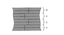
図11は第1コア部材と第2コア部材を二枚毎交互に積層した場合の断面図である。複数枚づつ交互に重ね合わせると、各コア片を連結手段(例えば、凸部及び凹部)で回動するとき、複数枚づつの枚数が多くなるほど、摩擦が減少し、生産性が向上する。
【0005】
【発明が解決しようとする課題】
従来の電動機は以上のように構成されており、第1コア部材4と第2コア部材5の重なりあわせを一枚毎交互にする構成をとる場合は、各コア片を連結手段(例えば、凸部及び凹部)で回動するときの、第1コア部材4と第2コア部材5の摩擦が大きく、特に積層厚さが多い場合や、板厚の薄いコア部材としたため積層枚数が多い場合に回動させるための力が大きく必要となり、生産性が悪化するという問題点があった。
【0006】
又、第1コア部材4と第2コア部材5の重なりあわせを複数枚づつ交互にした構成とした場合は、摩擦の問題は少なくなるものの、積層厚さの微調整がしにくくなる問題がある。電動機鉄心の積層厚さは、鉄心プレス機においてコア材料の厚みを考慮し、コア部材積層枚数を指令値として制御されるのが一般的である。しかしながら、コア材料の厚みがロット内でばらつき変化した場合、鉄心の積厚ばらつきを発生させる。このばらつきが管理許容値を超えた場合、積層端部にあたるコア部材をはがして、積層厚みの微調整を行うことがあるが、この時、一枚毎の重なり合わせならば、一枚毎コア部材をはがし積厚調整ができるものの、複数枚毎交互重なりあわせの場合は、コア部材をはがす際に複数枚まとめてはがれてしまい、微調整が難しいという問題点があった。
【0007】
この発明は、上記のような問題点を解決するためになされたもので、製造時のコア回動力の低減と積厚の微調整が可能な電動機を提供することを目的とする。
【0008】
【課題を解決するための手段】
この発明に係る鉄心装置は、板状の第1コア片を複数個連続的に配列する第1コア部材と、板状の第2コア片を複数個連続的に配列する第2コア部材とを、積層方向に交互に、第1コア部材の各第1コア片間位置と第2コア部材の各第2コア片間位置とが長手方向にずれて、前記各コア片の積層方向に相隣る縁部同士が重なり合うように積層され、相隣る各コア片の縁部同士を連結する連結手段が設けられ、連結手段で各コア片を回動させることにより環状又は矩形状に形成された鉄心装置において、一枚もしくは複数枚毎交互に重ね合わせられる第一コア部材と第2コア部材のそれぞれの積層方向の重なり合わせを、積層中央部よりも積層端部において少ない枚数毎としたことを特徴とする。
【0009】
また、この発明に係る鉄心装置は、第1コア部材と第2コア部材の積層方向の重なり合わせを、積層中央部は複数枚毎とし、積層端部は一枚毎交互に重なり合うようにしたことを特徴とする。
【0011】
また、この発明に係る鉄心装置は、第1コア部材と第2コア部材の積層方向の重なり合わせを、積層中央部よりも、透孔が設けられる積層端部とは逆側の積層端部において少ない枚数毎としたことを特徴とする。
【0012】
また、この発明に係る鉄心装置は、第1コア部材と第2コア部材の積層方向の重なり合わせを、積層中央部は複数枚毎とし、透孔が設けられる積層端部とは逆側の積層端部は一枚毎交互に重なり合うようにしたことを特徴とする。
【0014】
また、この発明に係る鉄心装置は、連結手段は、第1コア部材の第1コア片の一端側縁部表裏面と、第2コア部材の第2コア片の他端側縁部表裏面にそれぞれ形成され、コア片の積層方向に相隣る縁部同士が嵌合可能な凹部および凸部で構成されていることを特徴とする。
【0015】
また、この発明に係る鉄心装置は、連結手段は、ピン部材を用いたピン接続としたことを特徴とする。
【0016】
また、この発明に係る鉄心装置は、連結手段は、バックヨークの薄肉部を折り曲げるものとしたことを特徴とする。
【0017】
この発明に係る永久磁石形電動機は、請求項1〜7の何れかに記載の鉄心装置と、永久磁石を設けた回転子とを備えたことを特徴とする。
【0018】
この発明に係る密閉形圧縮機は、請求項8に記載の永久磁石形電動機を用いたことを特徴とする。
【0019】
この発明に係る鉄心装置の製造方法は、板状の第1コア片を複数個連続的に配列する第1コア部材と、板状の第2コア片を複数個連続的に配列する第2コア部材とを、積層方向に交互に、かつ各コア部材の積層方向の重なり合わせを、積層中央部よりも積層端部において少ない枚数毎に、第1コア部材の各第1コア片間位置と第2コア部材の各第2コア片間位置とが長手方向にずれて、各コア片の積層方向に相隣る縁部同士が重なり合うように積層する工程と、相隣る各コア片の縁部同士を連結する連結手段を設ける工程と、連結手段で各コア片を回動させることにより環状又は矩形状に形成する工程とを備えたことを特徴とする。
【0020】
また、この発明に係る鉄心装置の製造方法は、第1コア部材と第2コア部材の積層方向の重なり合わせを、積層中央部は複数枚毎とし、積層端部は一枚毎交互に重なり合うようにしたことを特徴とする。
【0028】
また、この発明に係る鉄心装置の製造方法は、コア部材逆反り状態で巻線を施したされた後、連結手段で各コア片を回動させることにより環状又は矩形状に形成することを特徴とする。
【0029】
また、この発明に係る鉄心装置の製造方法は、コア片の縁部の凸部および凹部が形成され、積層コアのかしめ結合用凹凸部がコア片の中央部に形成される第1の工程と、第1の工程で凹凸部が形成された周辺部分に、第1コア部材を加工する第2段階として、両端面及び両端面の周辺部を形成する第2の工程と、第1の工程で凹凸部が形成された周辺部分に、第2コア部材を加工する第2段階として、両端面及び両端面の周辺部を形成する第3の工程と、第2の工程と第3の工程で両端面が形成された部分を、順次交互にプレス打ち抜きすることにより、それぞれ第1コア部材、第2コア部材が形成され、これらの第1コア部材、第2コア部材は金型内で順次積層される第4の工程と、とを備え、第1コア部材と第2コア部材をそれぞれ複数枚ずつ交互に積層し、それぞれの積層方向の重なり合わせを、積層中央部よりも、積層端部において少ない枚数毎とする場合、第2の工程と第3の工程のプレス打抜きの間欠動作をそれぞれ重なり合わせ枚数毎複数回毎交互に行うことを特徴とする。
また、この発明に係る鉄心装置の製造方法は、コアの積層厚を測定し、指定寸法値よりも厚い場合には、コア枚数を1枚、もしくは複数枚剥がして積層厚を調整する工程を設けたことを特徴とする。
【0030】
【発明の実施の形態】
実施の形態1.
以下、この発明の実施の形態の一例を図面に基づいて説明する。
図1〜9は実施の形態1を示す図で、図1は鉄心装置の構成を示す平面図、図2は図1に示すコア部材をプレス打ち抜きにより形成する工程を示す平面図、図3は図2に示す工程を経て形成されたコア部材の連結手段の構成を示す断面図、図4は図2に示す工程を経て形成されたコア部材が積層された状態を示す平面図、図5は図4に示すように積層されたコア部材の各コア片の縁部の構成を示す断面図、図6は巻線時のコア部材の姿勢を示す平面図、図7はコア部材の他の連結手段を示す構成図、図8はコア部材のさらに他の連結手段を示す構成図、図9は永久磁石形電動機の縦断面図である。
【0031】
図において、3は磁性材料でなる板状のコア片で、一端側縁部表裏面に連結手段としての凸部3bおよび凹部3aが形成されると共に、その端面3cはこれら凸部3bおよび凹部3aの中心を中心とした凸円弧状に形成され、他端側には相隣るコア片3の端面3cと嵌合可能な凹円弧状の端面3dが形成されている。
【0032】
図2に示すように、4は複数のコア片3が各端面3c、3dを介して連続的に配列された第1コア部材である。5は複数のコア片3が各端面3c、3dを介して連続的に配列された第2コア部材である。第1コア部材4のコア片3は一端側縁部表裏面に連結手段(すなわち連結機構)としての凸部3bおよび凹部3aが形成されており、第2コア部材5のコア片3は他端側縁部表裏面に連結手段(すなわち連結機構)としての凸部3bおよび凹部3aが形成されている。
【0033】
図3〜5に示すように、第1コア部材4と第2コア部材5は交互に積層され、第1コア部材4の各コア片間位置(すなわち各コア片端面3c、3d間位置)と第2コア部材5の各コア片間位置(すなわち各コア片端面3c、3d間位置)とが長手方向にずれて、各コア片の積層方向に相隣る縁部同士が重なり合うように積層されている。そして積層方向に相隣るコア片3の縁部同士において、第1コア部材4のコア片3の一端側縁部の凸部3bおよび凹部3aと、第2コア部材5のコア片3の他端側縁部の凸部3bおよび凹部3aとが嵌合されることにより回動自在に連結されている。
【0034】
この時、図5に示すように、第1コア部材4と第2コア部材5は積層方向中央部22では、複数枚毎に交互に積層され、積層端部20、21では1枚毎交互に積層されている。図5では積層中央部22において2枚ずつ交互に重ねわせているが、後述する特性が許す限り複数枚(例えば、2〜10枚づつ)を交互に重ね合わせても良い。複数枚づつ交互に重ね合わせると、各コア片3を連結手段(例えば、凸部3b及び凹部3a)で回動するとき、複数枚づつの枚数が多くなるほど、摩擦が減少し、生産性が向上する。
【0035】
しかし、一方、枚数が多くなればなるほど、プレスで打ち抜かれた端面3c、3dが同一平面内に存在し、この端面には絶縁皮膜が存在しないため、積層方向に渦電流が発生しやすくなり、この渦電流により鉄損を生じ磁気性能を低下させるという問題点がある。
【0036】
また、第1コア部材4のコア片3の一端側縁部の凸部3bおよび凹部3aと、第2コア部材5のコア片3の他端側縁部の凸部3bおよび凹部3aとの嵌合により持たせていた機械的強度が低下するといった問題が生じる。
【0037】
すなわち、複数枚毎の積層枚数は摩擦力低減による生産性と、磁気性能と、機械的強度を考慮して決定される値である。また、積層端部20、21においては、第1コア部材4と第2コア部材5の重なり合わせを積層中央部22に対し少ない枚数毎としている(図では一枚毎)。この時、積層端部20、21の長さは積層中央部22の長さに対し充分短いものになっており、回動時の摩擦力による生産性、磁気性能、機械強度においてはおおよそ積層中央部22の特性となるようにされている。
【0038】
電動機鉄心の積層厚さは、鉄心プレス機においてコア材料の厚みを考慮し、コア部材積層枚数を指令値として制御されるのが一般的である。しかしながら、コア材料の厚みがロット内でばらつき変化した場合、鉄心の積厚ばらつきを発生させる。このばらつきが管理許容値を超えた場合、積層端部20、21にあたるコア部材をはがして、積層厚みの微調整を行うことがあるが、この時、一枚毎の重なり合わせならば、一枚毎コア部材をはがし積厚調整ができるものの、複数枚毎交互重なりあわせの場合は、コア部材をはがす際に複数枚まとめてはがれてしまい微調整が難しいという問題点がある。
【0039】
しかしながら、本発明によればコア部材をはがすことにより厚みを調整される積厚端部20、21は、1枚毎もしくは必要最小枚毎の重ね合わせになっているため、生産性向上のため積厚中央部22を複数枚ラップとしても、鉄心積厚の微調整ができるものとなっている。また、積層端部は、鉄心上部、下部両側であっても良いし、片側でも良い。
【0040】
通常積層端部20には、図3に示すように透孔3eが設けられ、コア片3の縁部の凸部3b及びコア片3の中央部に配置されるかしめ結合用凸部3gと嵌合される。この透孔3eは連続的に積層されるプレス機金型内にて、所望の厚みに鉄心積層厚みを調整するとともに、凸部が鉄心から出ないように設けられる。このため、鉄心積厚の微調整は透孔3eとは逆側の積層端部21をはがすことによって調整される。つまり、この意味においては積層端部の1枚毎もしくは必要最小枚毎の重ね合わせは、少なくとも透孔3eとは逆側の積層端部21のみにあれば良いことになる。
【0041】
また、図1の6は各コア片3の磁極ティース3f(図4)にそれぞれ巻回された巻線、7は積層された両コア部材4、5の各コア片3の凹、凸部3a、3bを回動させることによって環状に形成された鉄心装置である。なお、図1で、第1コア部材4と第2コア部材5とを積層した積層コアの端部同士(環状体の繋ぎ目)においては、端部同士を当接結合させるために、連結手段(凸部3bおよび凹部3a)が、省略されている。
【0042】
次に、上記のように構成された実施の形態1における鉄心装置の製造方法について説明する。まず、図2に矢印Tで示す位置において、コア部材の表裏面に圧入嵌合可能な凸部および凹部が、各コア片につき3箇所プレス打ち抜き動作によって形成される。この第1段階で、図3に示すように、コア片3の縁部の凸部3bおよび凹部3aが形成され、積層コアのかしめ結合用凹凸部がコア片3の中央部に形成される(図では2個)。
【0043】
矢印Aで示す位置において、矢印Tの段階で凹凸部が形成された周辺部分に、第1コア部材4を加工する第2段階として、図中ハッチングで示す部分をプレス打ち抜きすることにより両端面3c、3d及び両端面3c、3dの周辺部を形成する。又、矢印Bで示す位置においては、矢印Tの段階で凹凸部が形成された周辺部分に、第2コア部材5を加工する第2段階として、図中ハッチングで示す部分をプレス打ち抜きすることにより両端面3c、3d及び両端面3c、3dの周辺部を形成する。
【0044】
次いで、図2に矢印Cで示す位置において、矢印Aの段階で両端面3c、3dが形成された部分と、矢印Bの段階で両端面3c、3dが形成された部分を、順次交互に図中ハッチングで示す部分をプレス打ち抜きすることにより、それぞれ第1コア部材4、第2コア部材5が形成され、これらの第1コア部材4、第2コア部材5は金型内で順次積層される。
【0045】
矢印A部と矢印B部のプレス打抜きは間欠動作ができるようになっており、矢印Aの位置でプレス打ち抜きされた第1コア部材4は、コア部材が金型内で順送りされ、矢印Bの位置では打ち抜きをせずに順送りされ、矢印Cで示す位置にて図中ハッチングで示す部分をプレス打ち抜きする。第1コア部材4と第2コア部材5を交互に積層する場合は、次に、矢印Aの位置では打ち抜きをせずに順送りされ、矢印Bの位置でプレス打ち抜きされた第2コア部材5を矢印Cで示す位置にて図中ハッチングで示す部分をプレス打ち抜きするのと同時に、先に打ち抜かれた第1コア部材4にカシメられ積層される。これを順次繰り返すことにより第1コア部材4と第2コア部材5が交互に積層される。
【0046】
第1コア部材4と第2コア部材5をそれぞれ2枚ずつ交互に積層する場合には、矢印A部と矢印B部のプレス打抜きの間欠動作をそれぞれ2回毎交互に行い、「矢印A部で打ち抜き−矢印B部は打ち抜かず順送り−矢印C部で打ち抜き」を2回連続して行ったあと、「矢印A部は打ち抜かず順送り−矢印B部で打ち抜き−矢印C部で打ち抜き」を2回連続して行う。これを繰り返すことによって第1コア部材4と第2コア部材5が2枚毎交互に重なりあうようになる。このように、プレス打抜きの間欠動作によって、自由に複数枚毎の重なり合わせが可能となる。間欠動作を鉄心積層端部と積層中央部で変化させれば、重なり合わせ枚数も変化させることができる。
【0047】
又、矢印Sで示す位置において、矢印Tの段階で形成する凹凸部と同じ位置に各コア片につき3箇所の透孔がプレス打ち抜き動作によって形成される。これにより、積層コアの最上層となるコア片3に、凸部3bが嵌合可能な3箇所の透孔3eが形成される。矢印Bで示す位置において、矢印Sの段階で透孔3eが形成された部分に、第3コア部材51を加工する第2段階として、図中ハッチングで示す部分をプレス打ち抜きすることにより両端面3c、3d及び両端面3c、3dの周辺部を形成する。矢印Cで示す位置において、矢印Bの段階で両端面3c、3dが形成された部分に図中ハッチングで示す部分をプレス打ち抜きすることにより、第3コア部材51が形成され、積層コアの最上層として、金型内に積層される。
【0048】
例えば、積層厚みを75mmにしたい場合には、コア材料の厚みを0.35mmとした時、コア片の積層枚数は約214枚であり、214枚目に透孔3e付きのコア片とすれば、所望の積層積厚を得ることができる。
【0049】
なお、図2において、第1コア部材4や第2コア部材5の両端のコア片3は、中央のコア片3と縁部において一部不揃いである。これは、両端のコア片3が第1コア部材4と第2コア部材5とを積層した積層コアの端部同士にあたり、端部同士を当接結合させ易くするためである。以下、積層コアの両端のコア片が、中央のコア片と一部不揃いであるのは、このためである。
【0050】
金型内で各コア片3の積層方向で相対向する凹部3aおよび凸部3b、透孔3eおよび凸部3b同士が圧入嵌合されるとともに、抜きかしめがなされ図4に示すように一体化される。そして、積層されたコア部材4、5および51の各コア片3の磁極ティース3fには、図4に示すようにコア部材直線展開状態もしくは、図6で示すようなコア部材逆反り状態で巻線6(図示せず)が施された後、嵌合された凹部3aおよび凸部3b、透孔3eおよび凸部3bを回動させることにより環状に形成して鉄心装置7が完成する。
【0051】
図4はコア片3を直線状に配列させた場合であるが、図6のように逆反り状態にして、巻線を施せばさらに巻線工作性が改善される。
【0052】
上記製造方法においては、コア部材の打ち抜きはコア片を直線状に配置している例を上げているが、コア片を最終電動機鉄心形状の円環状に配置するように打ち抜いても良い。電動機鉄心としての最終形状にて予めプレス打ち抜きをし、その後コア片を展開して巻線をし、打ち抜き状態の円環状に戻せば、より精度のよい電動機を得ることができる。
【0053】
また、本実施の形態では、縁部同士を連結する連結手段として、嵌合可能な凹部および凸部にての例を示しているが、連結手段としては、図7のようにピン部材17を用いたピン接続のものでも良いし、図8のようにバックヨークの薄肉部23を折り曲げるタイプのものでも同様の効果を得ることができるが、コア片に凹部、凸部をつけた本実施の形態のものが最も精度、生産上有効である。
【0054】
また、回転子として永久磁石を用いた電動機、例えばブラシレスDCモータなどの場合には次のような効果も期待できる。図9は永久磁石型電動機の縦断面図であるが、永久磁石型電動機は固定子24よりも回転子25の方が積厚が厚いのが一般的である。これは、永久磁石26の磁力を有効に使用するためで、固定子よりオーバーハングした回転子の永久磁石の矢印で示した磁束28は回転子外周鉄部27を通り、固定子に回り込む。このため、固定子の磁束密度は積層中央部22より積層端部20、21の方が高く、コア片間の端面3c、3dの渦電流が発生しやすくなるが、本発明の形態とすれば、積層端部での重なり合わせ枚数を少ない枚数毎としているため、渦電流の影響を低減でき効率の良い永久磁石形電動機とすることができる。
【0055】
また、上記永久磁石形電動機を密閉形圧縮機に使用すれば、密閉形圧縮機の性能を向上することができる。
【0056】
【発明の効果】
この発明の請求項1に係る鉄心装置は、第一コア部材と第2コア部材のそれぞれの積層方向の重なり合わせを、積層中央部よりも積層端部において少ない枚数毎としたことにより、巻線時に巻線しやすいよう積層鉄心を展開するためにコア片を回動する際の力を軽減できると共に、鉄心積層積厚の微調整が容易になる。
【0057】
また、この発明の請求項2に係る鉄心装置は、第1コア部材と第2コア部材の積層方向の重なり合わせを、積層中央部は複数枚毎とし、積層端部は一枚毎交互に重なり合うようにしたことにより、巻線時に巻線しやすいよう積層鉄心を展開するためにコア片を回動する際の力を軽減できると共に、鉄心積層積厚の微調整が容易になる。
【0059】
また、この発明の請求項3に係る鉄心装置は、第1コア部材と第2コア部材の積層方向の重なり合わせを、積層中央部よりも、透孔が設けられる積層端部とは逆側の積層端部において少ない枚数毎としたことにより、鉄心積層積厚の微調整を確実に行うことができる。
【0060】
また、この発明の請求項4に係る鉄心装置は、第1コア部材と第2コア部材の積層方向の重なり合わせを、積層中央部は複数枚毎とし、透孔が設けられる積層端部とは逆側の積層端部は一枚毎交互に重なり合うようにしたことにより、鉄心積層積厚の微調整を確実に行うことができる。
【0062】
また、この発明の請求項5に係る鉄心装置は、連結手段は、第1コア部材の第1コア片の一端側縁部表裏面と、第2コア部材の第2コア片の他端側縁部表裏面にそれぞれ形成され、コア片の積層方向に相隣る縁部同士が嵌合可能な凹部および凸部で構成されていることにより、精度が良く、生産性の高い鉄心装置を得ることができる。
【0063】
また、この発明の請求項6に係る鉄心装置は、連結手段は、ピン部材を用いたピン接続としたことにより、精度が良く、生産性の高い鉄心装置を得ることができる。
【0064】
また、この発明の請求項7に係る鉄心装置は、連結手段は、バックヨークの薄肉部を折り曲げるものとしたことにより、生産性の高い鉄心装置を得ることができる。
【0065】
この発明の請求項8に係る永久磁石形電動機は、請求項1〜7の何れかに記載の鉄心装置と、永久磁石を設けた回転子とを備えたことにより、高効率な永久磁石形電動機を得ることができる。
【0066】
この発明の請求項9に係る密閉形圧縮機は、請求項8に記載の永久磁石形電動機を用いたことにより、高性能の密閉形圧縮機を得ることができる。
【0067】
この発明の請求項10に係る鉄心装置の製造方法は、板状の第1コア片を複数個連続的に配列する第1コア部材と、板状の第2コア片を複数個連続的に配列する第2コア部材とを、積層方向に交互に、かつ各コア部材の積層方向の重なり合わせを、積層中央部よりも積層端部において少ない枚数毎に、第1コア部材の各第1コア片間位置と第2コア部材の各第2コア片間位置とが長手方向にずれて、各コア片の積層方向に相隣る縁部同士が重なり合うように積層する工程と、相隣る各コア片の縁部同士を連結する連結手段を設ける工程と、連結手段で各コア片を回動させることにより環状又は矩形状に形成する工程とを備えたことにより、巻線時に巻線しやすいよう積層鉄心を展開するためにコア片を回動する際の力を軽減できると共に、鉄心積層積厚の微調整が容易になる。
【0068】
また、この発明の請求項11に係る鉄心装置の製造方法は、第1コア部材と第2コア部材の積層方向の重なり合わせを、積層中央部は複数枚毎とし、積層端部は一枚毎交互に重なり合うようにしたことにより、巻線時に巻線しやすいよう積層鉄心を展開するためにコア片を回動する際の力を軽減できると共に、鉄心積層積厚の微調整が容易になる。
【0076】
また、この発明の請求項12に係る鉄心装置の製造方法は、コア部材逆反り状態で巻線を施したされた後、連結手段で各コア片を回動させることにより環状又は矩形状に形成することにより、巻線工作性が改善される。
【0077】
また、この発明の請求項13に係る鉄心装置の製造方法は、コア片の縁部の凸部および凹部が形成され、積層コアのかしめ結合用凹凸部がコア片の中央部に形成される第1の工程と、第1の工程で凹凸部が形成された周辺部分に、第1コア部材を加工する第2段階として、両端面及び両端面の周辺部を形成する第2の工程と、第1の工程で凹凸部が形成された周辺部分に、第2コア部材を加工する第2段階として、両端面及び両端面の周辺部を形成する第3の工程と、第2の工程と第3の工程で両端面が形成された部分を、順次交互にプレス打ち抜きすることにより、それぞれ第1コア部材、第2コア部材が形成され、これらの第1コア部材、第2コア部材は金型内で順次積層される第4の工程と、とを備え、第1コア部材と第2コア部材をそれぞれ複数枚ずつ交互に積層し、それぞれの積層方向の重なり合わせを、積層中央部よりも、積層端部において少ない枚数毎とする場合、第2の工程と第3の工程のプレス打抜きの間欠動作をそれぞれ重なり合わせ枚数毎複数回毎交互に行うことにより、自由に複数枚毎の重なり合わせが可能となる。
また、この発明の請求項14に係る鉄心装置の製造方法は、コアの積層厚を測定し、指定寸法値よりも厚い場合には、コア枚数を1枚、もしくは複数枚剥がして積層厚を調整する工程を設けたことにより、鉄心積厚の微調整ができる。
【図面の簡単な説明】
【図1】 実施の形態1を示す図で、鉄心装置の構成を示す平面図である。
【図2】 図1に示すコア部材をプレス打ち抜きにより形成する工程を示す平面図である。
【図3】 図2に示す工程を経て形成されたコア部材の連結手段の構成を示す断面図である。
【図4】 図2に示す工程を経て形成されたコア部材が積層された状態を示す平面図である。
【図5】 図4に示すように積層されたコア部材の各コア片の縁部の構成を示す断面図である。
【図6】 実施の形態1を示す図で、巻線時のコア部材の姿勢を示す平面図である。
【図7】 実施の形態1を示す図で、コア部材の他の連結手段を示す構成図である。
【図8】 実施の形態1を示す図で、コア部材のさらに他の連結手段を示す構成図である。
【図9】 実施の形態1を示す図で、永久磁石形電動機の縦断面図である。
【図10】 従来の鉄心装置における積層されたコア部材の各コア片の縁部の構成を示す断面図である。
【図11】 従来の鉄心装置における積層されたコア部材の各コア片の縁部で、図10とは異なる構成を示す断面図である。
【符号の説明】
3 コア片、3a 凹部、3b 凸部、3c,3d 端面、3e 透孔、3f磁極ティース、3g かしめ結合用凸部、4 第1コア部材、5 第2コア部材、6 巻線、7 鉄心装置、17 ピン部材、20,21 積層端部、22 積層中央部、23 薄肉部、24 固定子、25 回転子、26 永久磁石、27 回転子外周鉄部、28 磁束、51 第3コア部材。[0001]
BACKGROUND OF THE INVENTION
The present invention relates to an electric motor used for a compressor or the like, and more particularly to a configuration of a stator core.
[0002]
[Prior art]
The applicant is disclosed in Japanese Patent Application Laid-Open No. 2000-201458 in which a first core member that continuously arranges a plurality of plate-like first core pieces and a second that continuously arranges a plurality of plate-like second core pieces. The core members are alternately displaced by a predetermined number in the stacking direction, the positions between the first core pieces of the first core member and the positions between the second core pieces of the second core member are shifted in the longitudinal direction, and each core piece The adjacent edges in the stacking direction are stacked so that the adjacent edges overlap each other, and connecting means for connecting the edges of the adjacent core pieces are provided. It has been proposed to produce an electric motor core formed in an annular or rectangular shape by rotating a piece.
[0003]
FIG. 10 is a cross-sectional view when the first core member and the second core member are alternately stacked one by one. In the figure, 4 is a first core member, 5 is a second core member, and 51 is a third core member which is the uppermost layer of the laminated core. By being configured in this way, the edges adjacent to each other in the stacking direction of the core pieces are stacked so that the end faces of the punched core pieces are alternately shifted by the overlapped dimension. (That is, since the end faces of the core pieces are not continuous), the area of the portion existing in the same plane is reduced, so that the generation of eddy currents can be suppressed, the iron loss can be reduced, and the magnetic performance can be improved. .
[0004]
FIG. 11 is a cross-sectional view when the first core member and the second core member are alternately laminated every two sheets. When a plurality of sheets are alternately overlapped, when each core piece is rotated by a connecting means (for example, a convex part and a concave part), the friction decreases and the productivity increases as the number of the plurality of sheets increases.
[0005]
[Problems to be solved by the invention]
The conventional electric motor is configured as described above, and in the case where the overlapping of the first core member 4 and the
[0006]
Further, when the first core member 4 and the
[0007]
The present invention has been made to solve the above-described problems, and an object of the present invention is to provide an electric motor capable of reducing the core turning power during manufacture and finely adjusting the thickness.
[0008]
[Means for Solving the Problems]
The iron core device according to the present invention includes a first core member that continuously arranges a plurality of plate-like first core pieces, and a second core member that continuously arranges a plurality of plate-like second core pieces. The positions between the first core pieces of the first core member and the positions between the second core pieces of the second core member are displaced in the longitudinal direction alternately in the stacking direction, and are adjacent to each other in the stacking direction of the core pieces. Are connected so that the edges of the core pieces adjacent to each other are connected to each other, and connecting means for connecting the edges of the adjacent core pieces are provided. In iron core equipment,One or more sheets are stacked alternatelyThe overlapping of the first core member and the second core member in the stacking direction is made smaller at the stack end than at the stack center.
[0009]
Further, in the iron core device according to the present invention, the overlapping of the first core member and the second core member in the stacking direction is made such that the stacking central portion is every plural pieces, and the stacking end portions are overlapped alternately one by one. It is characterized by.
[0011]
In the iron core device according to the present invention, the stacking direction of the first core member and the second core member is overlapped in the stacking end portion opposite to the stacking end portion where the through holes are provided, rather than the stacking central portion. It is characterized by a small number of sheets.
[0012]
In the iron core device according to the present invention, the first core member and the second core member are overlapped in the stacking direction, the stacking center portion is provided for each of a plurality of sheets, and the stacking layer is opposite to the stacking end portion where the through holes are provided. The end portions are alternately overlapped one by one.
[0014]
Moreover, as for the iron core apparatus which concerns on this invention, a connection means is on the one end side edge part front and back of the 1st core piece of a 1st core member, and the other end side edge part front and back of a 2nd core piece of a 2nd core member. It is formed by the recessed part and convex part which are respectively formed and the edge parts adjacent to the lamination direction of a core piece can fit.
[0015]
The iron core device according to the present invention is characterized in that the connecting means is a pin connection using a pin member.
[0016]
The iron core device according to the present invention is characterized in that the connecting means bends the thin portion of the back yoke.
[0017]
A permanent magnet type electric motor according to the present invention comprises:7The iron core device according to any one of the above and a rotor provided with permanent magnets are provided.
[0018]
The hermetic compressor according to the present invention is as follows.8The permanent magnet type motor described in 1 is used.
[0019]
The manufacturing method of the iron core device according to the present invention includes a first core member that continuously arranges a plurality of plate-like first core pieces and a second core that continuously arranges a plurality of plate-like second core pieces. The members are alternately arranged in the stacking direction, and the overlapping in the stacking direction of each core member is made smaller than the center of the stack at the number of the end portions of the stack, and the positions between the first core pieces of the first core member and the first core member. The step of laminating the two core members so that the positions between the second core pieces are shifted in the longitudinal direction and the adjacent edges overlap in the stacking direction of the core pieces, and the edges of the adjacent core pieces It is characterized by comprising a step of providing a connecting means for connecting each other, and a step of forming each core piece in an annular or rectangular shape by rotating the core pieces by the connecting means.
[0020]
In the manufacturing method of the iron core device according to the present invention, the stacking direction of the first core member and the second core member is set to be a plurality of stacked central portions, and the stacked end portions are alternately stacked. It is characterized by that.
[0028]
In addition, the manufacturing method of the iron core device according to the present invention is characterized in that after the core member is wound in a reverse warped state, each core piece is rotated by a connecting means to form an annular or rectangular shape. And
[0029]
Moreover, the manufacturing method of the iron core device according to the present invention includes the first step in which the convex portion and the concave portion of the edge portion of the core piece are formed, and the concave and convex portion for caulking coupling of the laminated core is formed in the central portion of the core piece. As the second step of processing the first core member in the peripheral portion where the uneven portion is formed in the first step, the second step of forming both end surfaces and the peripheral portions of both end surfaces, and the first step As a second step of processing the second core member in the peripheral portion where the irregularities are formed, a third step of forming both end surfaces and peripheral portions of both end surfaces, and both ends in the second step and the third step The first core member and the second core member are respectively formed by sequentially pressing and punching the portion where the surface is formed, and the first core member and the second core member are sequentially laminated in the mold. And a plurality of first core members and a plurality of second core members, respectively. Alternately stacked one byIn each stacking direction, the overlapping in each stacking direction is less than the center of the stack and every few sheets at the stack end.When performing the press punching intermittent operation of the second step and the third step, respectivelyFor each overlapping numberIt is characterized by alternately performing a plurality of times.
In addition, the manufacturing method of the iron core device according to the present invention includes a step of measuring the laminated thickness of the cores and, when thicker than the specified dimension value, removing one or more cores and adjusting the laminated thickness. It is characterized by that.
[0030]
DETAILED DESCRIPTION OF THE INVENTION
Hereinafter, an example of an embodiment of the present invention will be described with reference to the drawings.
1 to 9 are views showing the first embodiment, FIG. 1 is a plan view showing the configuration of the iron core device, FIG. 2 is a plan view showing a process of forming the core member shown in FIG. 1 by press punching, and FIG. FIG. 4 is a cross-sectional view showing the structure of the connecting means for the core member formed through the process shown in FIG. 2, FIG. 4 is a plan view showing a state in which the core members formed through the process shown in FIG. 4 is a cross-sectional view showing the configuration of the edge of each core piece of the core members laminated as shown in FIG. 4, FIG. 6 is a plan view showing the posture of the core member during winding, and FIG. 7 is another connection of the core members FIG. 8 is a block diagram showing still another connecting means for the core member, and FIG. 9 is a longitudinal sectional view of the permanent magnet motor.
[0031]
In the figure,
[0032]
As shown in FIG. 2, reference numeral 4 denotes a first core member in which a plurality of
[0033]
As shown in FIGS. 3-5, the 1st core member 4 and the
[0034]
At this time, as shown in FIG. 5, the first core member 4 and the
[0035]
However, on the other hand, as the number increases, the end faces 3c and 3d punched by the press exist in the same plane, and since there is no insulating film on the end faces, eddy currents are more likely to occur in the stacking direction. This eddy current has a problem of causing iron loss and lowering the magnetic performance.
[0036]
Further, the fitting between the
[0037]
That is, the number of laminated sheets is a value determined in consideration of productivity by reducing frictional force, magnetic performance, and mechanical strength. In addition, in the
[0038]
In general, the thickness of the motor core is controlled by taking the thickness of the core material in the core press as the command value. However, when the thickness of the core material varies within a lot, the core thickness varies. If this variation exceeds the control tolerance, the core member corresponding to the stacking
[0039]
However, according to the present invention, the
[0040]
Normally, the
[0041]
Further, 6 in FIG. 1 is a winding wound around the magnetic pole teeth 3f (FIG. 4) of each
[0042]
Next, a method for manufacturing the iron core device according to the first embodiment configured as described above will be described. First, at a position indicated by an arrow T in FIG. 2, convex portions and concave portions that can be press-fitted and fitted to the front and back surfaces of the core member are formed by press punching operation at three locations for each core piece. In this first stage, as shown in FIG. 3,
[0043]
At the position indicated by arrow A, both end faces 3c are formed by press-punching the portions indicated by hatching in the drawing as a second step in which the first core member 4 is processed in the peripheral portion where the irregularities are formed at the step indicated by arrow T. 3d and peripheral portions of both end faces 3c, 3d are formed. In addition, at the position indicated by the arrow B, as a second stage in which the
[0044]
Next, at a position indicated by an arrow C in FIG. 2, a portion where both end faces 3c, 3d are formed at the stage of the arrow A and a part where both end faces 3c, 3d are formed at the stage of the arrow B are alternately illustrated. The first core member 4 and the
[0045]
The press punching of the arrow A portion and the arrow B portion can perform an intermittent operation, and the first core member 4 press punched at the position of the arrow A is fed forward in the mold, and the arrow B At the position, it is fed forward without punching, and at the position indicated by the arrow C, the portion indicated by hatching in the drawing is press punched. In the case where the first core member 4 and the
[0046]
When the first core member 4 and the
[0047]
Further, at the position indicated by the arrow S, three through holes are formed in each core piece at the same position as the concavo-convex portion formed at the stage of the arrow T by a press punching operation. Thereby, the three through-
[0048]
For example, when it is desired to make the laminated thickness 75 mm, when the thickness of the core material is 0.35 mm, the number of laminated core pieces is about 214, and if the core piece with the through
[0049]
In FIG. 2, the
[0050]
The
[0051]
FIG. 4 shows the case where the
[0052]
In the above manufacturing method, the core member is punched in an example in which the core pieces are arranged in a straight line, but the core pieces may be punched out so as to be arranged in an annular shape of the final motor core. A motor with higher accuracy can be obtained by press punching in advance with the final shape as the motor core, then unfolding the core piece, winding it, and returning it to the punched annular shape.
[0053]
Moreover, in this Embodiment, although the example in the recessed part and convex part which can be fitted is shown as a connection means which connects edge parts, as a connection means, as shown in FIG. The pin connection used may be used, or the same effect can be obtained with the type in which the
[0054]
Further, in the case of an electric motor using a permanent magnet as a rotor, such as a brushless DC motor, the following effects can be expected. FIG. 9 is a longitudinal sectional view of a permanent magnet type electric motor. In general, the permanent magnet type electric motor is thicker in the
[0055]
Further, if the permanent magnet type motor is used in a hermetic compressor, the performance of the hermetic compressor can be improved.
[0056]
【The invention's effect】
In the iron core device according to
[0057]
In the iron core device according to claim 2 of the present invention, the stacking direction of the first core member and the second core member is overlapped in a plurality of sheets in the stacking central portion, and the stacking end portions are alternately stacked in one stack. By doing so, it is possible to reduce the force when the core piece is rotated in order to expand the laminated core so as to be easily wound during winding, and to facilitate fine adjustment of the laminated thickness of the core.
[0059]
Further, the claims of the present invention3In the iron core device according to the present invention, the stacking of the first core member and the second core member in the stacking direction is less than the center of the stack at each stack end opposite to the stack end where the through holes are provided. By doing so, fine adjustment of an iron core lamination layer thickness can be performed reliably.
[0060]
Further, the claims of the present invention4In the iron core device according to the present invention, the stacking direction of the first core member and the second core member is overlapped with each other in the stacking central portion, and the stacking end on the side opposite to the stacking end provided with the through hole is one. By overlapping each sheet alternately, fine adjustment of the core stack thickness can be performed reliably.
[0062]
Further, the claims of the present invention5In the iron core device according to the first aspect of the present invention, the connecting means is formed on one end side edge front and back surfaces of the first core piece of the first core member and on the other end side edge front and back surfaces of the second core piece of the second core member, respectively. By comprising the recessed part and convex part which can fit the edge parts which adjoin in the lamination direction of a core piece, a precision and high productivity iron core apparatus can be obtained.
[0063]
Further, the claims of the present invention6In the iron core apparatus according to the present invention, since the connecting means is a pin connection using a pin member, an iron core apparatus with high accuracy and high productivity can be obtained.
[0064]
Further, the claims of the present invention7In the iron core device according to the present invention, since the connecting means bends the thin portion of the back yoke, a highly productive iron core device can be obtained.
[0065]
Claims of the invention8A permanent magnet type electric motor according to claim 1.7By providing the iron core device according to any one of the above and a rotor provided with a permanent magnet, a highly efficient permanent magnet motor can be obtained.
[0066]
Claims of the invention9A hermetic compressor according to claim8A high-performance hermetic compressor can be obtained by using the permanent magnet type motor described in 1).
[0067]
[0068]
Moreover,
[0076]
Further, the claims of the present invention12According to the manufacturing method of the iron core device according to the present invention, the winding workability is obtained by forming each core piece in an annular or rectangular shape by rotating each core piece with a connecting means after winding in a state where the core member is reversely warped. Is improved.
[0077]
Further, the claims of the present invention13The manufacturing method of the iron core device according to the first step in which the convex part and the concave part of the edge of the core piece are formed, and the concave and convex part for caulking coupling of the laminated core is formed in the center part of the core piece, As a second step of processing the first core member in the peripheral portion where the uneven portion is formed in the process, the second step of forming both end surfaces and the peripheral portion of both end surfaces, and the uneven portion is formed in the first step. As a second step of processing the second core member in the peripheral portion, a third step of forming both end surfaces and peripheral portions of both end surfaces, and both end surfaces are formed in the second step and the third step. The first core member and the second core member are respectively formed by press punching the portions alternately and sequentially, and the first core member and the second core member are sequentially laminated in the mold. And alternately stacking a plurality of first core members and a plurality of second core members.In each stacking direction, the overlapping in each stacking direction is less than the center of the stack and every few sheets at the stack end.When performing the press punching intermittent operation of the second step and the third step, respectivelyFor each overlapping numberBy alternately performing a plurality of times, it is possible to freely overlap each other.
Further, in the method for manufacturing an iron core device according to claim 14 of the present invention, the thickness of the core is measured, and if the thickness is larger than the specified dimension value, one or a plurality of cores are peeled off to adjust the thickness. By providing the step to perform, the iron core thickness can be finely adjusted.
[Brief description of the drawings]
FIG. 1 shows the first embodiment and is a plan view showing the configuration of an iron core device.
FIG. 2 is a plan view showing a step of forming the core member shown in FIG. 1 by press punching.
3 is a cross-sectional view showing a configuration of a connecting means for core members formed through the process shown in FIG. 2;
4 is a plan view showing a state in which core members formed through the steps shown in FIG. 2 are stacked. FIG.
FIG. 5 is a cross-sectional view showing a configuration of an edge portion of each core piece of core members stacked as shown in FIG. 4;
FIG. 6 shows the first embodiment and is a plan view showing the posture of the core member during winding.
FIG. 7 shows the first embodiment, and is a configuration diagram showing another connecting means of the core member.
FIG. 8 is a diagram showing the first embodiment and is a configuration diagram showing still another connecting means of the core member.
FIG. 9 is a view showing the first embodiment and is a longitudinal sectional view of a permanent magnet type electric motor.
FIG. 10 is a cross-sectional view illustrating a configuration of an edge portion of each core piece of a core member stacked in a conventional iron core device.
11 is a cross-sectional view showing a configuration different from that of FIG. 10 at the edge of each core piece of the laminated core member in the conventional iron core device.
[Explanation of symbols]
3 core pieces, 3a concave portions, 3b convex portions, 3c, 3d end faces, 3e through holes, 3f magnetic pole teeth, 3g caulking coupling convex portions, 4 first core member, 5 second core member, 6 windings, 7 iron core device , 17 Pin member, 20, 21 Stack end, 22 Stack center, 23 Thin section, 24 Stator, 25 Rotor, 26 Permanent magnet, 27 Rotor outer peripheral iron section, 28 Magnetic flux, 51 Third core member.
Claims (14)
第1の工程で凹凸部が形成された周辺部分に、第1コア部材を加工する第2段階として、両端面及び両端面の周辺部を形成する第2の工程と、
第1の工程で凹凸部が形成された周辺部分に、第2コア部材を加工する第2段階として、両端面及び両端面の周辺部を形成する第3の工程と、
第2の工程と第3の工程で両端面が形成された部分を、順次交互にプレス打ち抜きすることにより、それぞれ第1コア部材、第2コア部材が形成され、これらの第1コア部材、第2コア部材は金型内で順次積層される第4の工程と、
とを備え、第1コア部材と第2コア部材をそれぞれ複数枚ずつ交互に積層し、それぞれの積層方向の重なり合わせを、積層中央部よりも、積層端部において少ない枚数毎とする場合、第2の工程と第3の工程のプレス打抜きの間欠動作をそれぞれ重なり合わせ枚数毎複数回毎交互に行うことを特徴とする鉄心装置の製造方法。A first step in which a convex portion and a concave portion of the edge of the core piece are formed, and a concave and convex portion for caulking and coupling of the laminated core is formed in the central portion of the core piece;
A second step of forming both end surfaces and peripheral portions of both end surfaces as a second step of processing the first core member in the peripheral portion where the irregularities are formed in the first step;
As a second step of processing the second core member in the peripheral portion where the uneven portion is formed in the first step, a third step of forming both end surfaces and peripheral portions of both end surfaces;
The first core member and the second core member are formed by alternately pressing and punching the portions where both end faces are formed in the second step and the third step, respectively. A fourth step in which the two-core member is sequentially laminated in the mold;
Each of the first core member and the second core member are alternately stacked , and the stacking direction in each stacking direction is set to be smaller at the stacking end portion than at the stacking center portion . A method of manufacturing an iron core device, wherein the intermittent operation of press punching in the step 2 and the third step is alternately performed a plurality of times for each overlapping number of sheets .
Priority Applications (1)
| Application Number | Priority Date | Filing Date | Title |
|---|---|---|---|
| JP2002077206A JP4027132B2 (en) | 2002-03-19 | 2002-03-19 | Iron core device, method for manufacturing iron core device, permanent magnet motor and hermetic compressor |
Applications Claiming Priority (1)
| Application Number | Priority Date | Filing Date | Title |
|---|---|---|---|
| JP2002077206A JP4027132B2 (en) | 2002-03-19 | 2002-03-19 | Iron core device, method for manufacturing iron core device, permanent magnet motor and hermetic compressor |
Publications (3)
| Publication Number | Publication Date |
|---|---|
| JP2003284268A JP2003284268A (en) | 2003-10-03 |
| JP2003284268A5 JP2003284268A5 (en) | 2005-07-21 |
| JP4027132B2 true JP4027132B2 (en) | 2007-12-26 |
Family
ID=29227921
Family Applications (1)
| Application Number | Title | Priority Date | Filing Date |
|---|---|---|---|
| JP2002077206A Expired - Lifetime JP4027132B2 (en) | 2002-03-19 | 2002-03-19 | Iron core device, method for manufacturing iron core device, permanent magnet motor and hermetic compressor |
Country Status (1)
| Country | Link |
|---|---|
| JP (1) | JP4027132B2 (en) |
Families Citing this family (8)
| Publication number | Priority date | Publication date | Assignee | Title |
|---|---|---|---|---|
| JP2006101629A (en) * | 2004-09-29 | 2006-04-13 | Mitsui High Tec Inc | Manufacturing method of laminated core |
| JP2007068310A (en) * | 2005-08-30 | 2007-03-15 | Aisin Seiki Co Ltd | Laminated winding core for rotary machine |
| JP5418186B2 (en) * | 2009-12-02 | 2014-02-19 | 株式会社安川電機 | Laminated core manufacturing apparatus and laminated core manufacturing method |
| BRPI1102872B1 (en) * | 2011-06-22 | 2019-07-30 | Embraco Indústria De Compressores E Soluções Em Refrigeração Ltda. | FORMATION OF A PACKAGE OF OVERLAPED METAL BLADES |
| JP5660993B2 (en) * | 2011-08-04 | 2015-01-28 | 三菱電機株式会社 | Laminated iron core |
| JP5738167B2 (en) * | 2011-12-22 | 2015-06-17 | 三菱電機株式会社 | Laminated iron core |
| JP5623498B2 (en) * | 2012-12-28 | 2014-11-12 | 三菱電機株式会社 | Stator core and stator, electric motor and compressor |
| WO2016208629A1 (en) * | 2015-06-24 | 2016-12-29 | 三菱電機株式会社 | Rotating electrical machine stator, rotating electrical machine, rotating electrical machine stator production method |
Family Cites Families (4)
| Publication number | Priority date | Publication date | Assignee | Title |
|---|---|---|---|---|
| JPS5793058U (en) * | 1980-11-26 | 1982-06-08 | ||
| JP3167640B2 (en) * | 1997-04-11 | 2001-05-21 | 株式会社東芝 | Rotating electric machine stator |
| JP3279279B2 (en) * | 1998-06-30 | 2002-04-30 | 三菱電機株式会社 | Iron core equipment |
| JP3604326B2 (en) * | 2000-05-29 | 2004-12-22 | 三菱電機株式会社 | Stator for rotating electric machine and method of manufacturing the same |
-
2002
- 2002-03-19 JP JP2002077206A patent/JP4027132B2/en not_active Expired - Lifetime
Also Published As
| Publication number | Publication date |
|---|---|
| JP2003284268A (en) | 2003-10-03 |
Similar Documents
| Publication | Publication Date | Title |
|---|---|---|
| JP5296888B2 (en) | Method for manufacturing molded stator of rotating electric machine | |
| JP5859297B2 (en) | Rotating electric machine | |
| JP4121008B2 (en) | Stator and manufacturing method thereof, and stator core member manufacturing apparatus | |
| WO2006028179A1 (en) | Method for manufacturing laminated core | |
| JP2000201458A (en) | Iron core device and its manufacture | |
| JP5212129B2 (en) | Manufacturing method of laminated core and manufacturing jig thereof | |
| WO2013051125A1 (en) | Laminated core manufacturing method and laminated core manufactured using same | |
| JP4934402B2 (en) | Armature manufacturing method and progressive mold apparatus | |
| JP4027132B2 (en) | Iron core device, method for manufacturing iron core device, permanent magnet motor and hermetic compressor | |
| JP2007221927A (en) | Stator core of rotating electric machine and method of manufacturing same | |
| JPH10304608A (en) | Motor | |
| JP3749478B2 (en) | Manufacturing method of laminated core | |
| JP5251384B2 (en) | Laminated core and manufacturing method thereof | |
| JP3439658B2 (en) | Iron core | |
| JP2000116074A (en) | Laminating die apparatus of core member and laminating method therefor | |
| JP3660532B2 (en) | Electric motor and method for manufacturing electric motor core | |
| JP6069475B2 (en) | Rotating electric machine | |
| JP2003061319A (en) | Method for producing stator | |
| JPH10234159A (en) | Formation of core for electric rotating machine | |
| JP2000152526A (en) | Laminated core | |
| JP4290998B2 (en) | Manufacturing method of rotating electrical machine | |
| JP2004320878A (en) | Manufacturing method of laminated core and laminated core | |
| JP4543415B2 (en) | Core structure of smooth armature winding AC servo motor and smooth armature winding AC servo motor using this core structure | |
| JP2003284268A5 (en) | ||
| JP6045638B2 (en) | Manufacturing method of laminated iron core |
Legal Events
| Date | Code | Title | Description |
|---|---|---|---|
| RD04 | Notification of resignation of power of attorney |
Free format text: JAPANESE INTERMEDIATE CODE: A7424 Effective date: 20040518 |
|
| RD04 | Notification of resignation of power of attorney |
Free format text: JAPANESE INTERMEDIATE CODE: A7424 Effective date: 20041025 |
|
| A521 | Request for written amendment filed |
Free format text: JAPANESE INTERMEDIATE CODE: A523 Effective date: 20041202 |
|
| A621 | Written request for application examination |
Free format text: JAPANESE INTERMEDIATE CODE: A621 Effective date: 20041202 |
|
| A977 | Report on retrieval |
Free format text: JAPANESE INTERMEDIATE CODE: A971007 Effective date: 20070927 |
|
| TRDD | Decision of grant or rejection written | ||
| A01 | Written decision to grant a patent or to grant a registration (utility model) |
Free format text: JAPANESE INTERMEDIATE CODE: A01 Effective date: 20071009 |
|
| A61 | First payment of annual fees (during grant procedure) |
Free format text: JAPANESE INTERMEDIATE CODE: A61 Effective date: 20071009 |
|
| FPAY | Renewal fee payment (event date is renewal date of database) |
Free format text: PAYMENT UNTIL: 20101019 Year of fee payment: 3 |
|
| R150 | Certificate of patent or registration of utility model |
Ref document number: 4027132 Country of ref document: JP Free format text: JAPANESE INTERMEDIATE CODE: R150 Free format text: JAPANESE INTERMEDIATE CODE: R150 |
|
| FPAY | Renewal fee payment (event date is renewal date of database) |
Free format text: PAYMENT UNTIL: 20111019 Year of fee payment: 4 |
|
| FPAY | Renewal fee payment (event date is renewal date of database) |
Free format text: PAYMENT UNTIL: 20121019 Year of fee payment: 5 |
|
| FPAY | Renewal fee payment (event date is renewal date of database) |
Free format text: PAYMENT UNTIL: 20131019 Year of fee payment: 6 |
|
| R250 | Receipt of annual fees |
Free format text: JAPANESE INTERMEDIATE CODE: R250 |
|
| R250 | Receipt of annual fees |
Free format text: JAPANESE INTERMEDIATE CODE: R250 |
|
| R250 | Receipt of annual fees |
Free format text: JAPANESE INTERMEDIATE CODE: R250 |
|
| R250 | Receipt of annual fees |
Free format text: JAPANESE INTERMEDIATE CODE: R250 |
|
| R250 | Receipt of annual fees |
Free format text: JAPANESE INTERMEDIATE CODE: R250 |
|
| R250 | Receipt of annual fees |
Free format text: JAPANESE INTERMEDIATE CODE: R250 |
|
| R250 | Receipt of annual fees |
Free format text: JAPANESE INTERMEDIATE CODE: R250 |
|
| EXPY | Cancellation because of completion of term |