JP5660993B2 - Laminated iron core - Google Patents
Laminated iron core Download PDFInfo
- Publication number
- JP5660993B2 JP5660993B2 JP2011171076A JP2011171076A JP5660993B2 JP 5660993 B2 JP5660993 B2 JP 5660993B2 JP 2011171076 A JP2011171076 A JP 2011171076A JP 2011171076 A JP2011171076 A JP 2011171076A JP 5660993 B2 JP5660993 B2 JP 5660993B2
- Authority
- JP
- Japan
- Prior art keywords
- core
- pieces
- laminated
- sheets
- members
- Prior art date
- Legal status (The legal status is an assumption and is not a legal conclusion. Google has not performed a legal analysis and makes no representation as to the accuracy of the status listed.)
- Active
Links
- XEEYBQQBJWHFJM-UHFFFAOYSA-N Iron Chemical group [Fe] XEEYBQQBJWHFJM-UHFFFAOYSA-N 0.000 title claims description 25
- 238000003475 lamination Methods 0.000 claims description 11
- 238000010030 laminating Methods 0.000 claims description 6
- 230000008878 coupling Effects 0.000 claims description 2
- 238000010168 coupling process Methods 0.000 claims description 2
- 238000005859 coupling reaction Methods 0.000 claims description 2
- 230000004907 flux Effects 0.000 description 5
- 238000003466 welding Methods 0.000 description 3
- 238000005336 cracking Methods 0.000 description 2
- 230000000694 effects Effects 0.000 description 2
- 238000006073 displacement reaction Methods 0.000 description 1
- 239000000463 material Substances 0.000 description 1
Images


Description
この発明は、回転電機の固定子鉄心を構成する積層鉄心の構造に関し、特に積層鉄心の磁気特性や組立作業性の改善に関するものである。 The present invention relates to a structure of a laminated core constituting a stator core of a rotating electric machine, and more particularly to improvement of magnetic characteristics and assembly workability of the laminated core.
従来の鉄心装置は、板状の第1コア片を複数個連続的に配列する第1コア部材と、板状の第2コア片を複数個連続的に配列する第2コア部材とが、積層方向に交互に、上記第1コア部材の各第1コア片間位置と上記第2コア部材の各第2コア片間位置とが長手方向にずれて、上記各コア片の積層方向に相隣る縁部同士が重なり合うように積層され、相隣る各コア片の縁部同士を連結する連結手段が設けられ、上記連結手段で上記各コア片を回動させることにより環状又は矩形状に形成されている。そして第1コア部材と第2コア部材とを1枚ずつ、または複数の同一枚数ずつ交互に積層している(例えば、特許文献1参照)。 In the conventional iron core device, a first core member that continuously arranges a plurality of plate-like first core pieces and a second core member that continuously arranges a plurality of plate-like second core pieces are laminated. Alternately in the direction, the position between the first core pieces of the first core member and the position between the second core pieces of the second core member are shifted in the longitudinal direction, and adjacent to each other in the stacking direction of the core pieces. Are connected so that the edges of adjacent core pieces are connected to each other, and are formed into an annular or rectangular shape by rotating the core pieces with the connecting means. Has been. And the 1st core member and the 2nd core member are laminated | stacked alternately one sheet each, or several same number (for example, refer patent document 1).
上記従来の鉄心装置は、第1コア部材と第2コア部材を同一枚数ずつ交互に積層する構成である。例えば第1コア部材と第2コア部材とを1枚ずつ交互に積層する場合など、全ての第1コア部材と第2コア部材の枚数を等しく少なく積層した構造では、連結手段により各コア片を回動するときの摩擦が大きくなり、鉄心装置の寸法精度や組立作業性が悪化するという問題があった。また仮に、第1コア部材と第2コア部材の枚数を等しく多く積層すれば、磁路抵抗が増加し磁気特性が悪化するという問題が生じる。
この発明は、上記のような課題を解決するためになされたもので、連結手段により各コア片を回動する際の摩擦を抑えるとともに、磁路抵抗を低減した積層鉄心を得ることを目的とする。
The conventional iron core device has a configuration in which the same number of first core members and second core members are alternately stacked. For example, when the first core member and the second core member are alternately stacked one by one, in a structure in which the number of all the first core members and the second core members are equally small, each core piece is connected by the connecting means. There was a problem that the friction when rotating increased, and the dimensional accuracy and assembly workability of the iron core device deteriorated. Also, if the first core member and the second core member are laminated in an equal number, the magnetic path resistance increases and the magnetic characteristics deteriorate.
The present invention was made to solve the above-described problems, and has an object to obtain a laminated core with reduced magnetic path resistance while suppressing friction when each core piece is rotated by a connecting means. To do.
この発明に係る積層鉄心は、複数の板状の第1コア片を連続的に配列してなる第1コアシートを1枚又は複数枚重ねて形成される第1コア部材と、複数の板状の第2コア片を連続的に配列してなる第2コアシートを1枚又は複数枚重ねて形成される第2コア部材とが、上記第1コア部材の各第1コア片間位置と上記第2コア部材の各第2コア片間位置とを長手方向にずらして、上記各第1コア片と上記各第2コア片との積層方向に相隣る縁部同士が重なり合うように交互に積層され、上記第1、第2コア片の重なり合う縁部に上記縁部同士を回動自在に連結する連結手段を備えている。そして、上記第1、第2の各コア部材を形成する上記第1、第2コアシートの枚数は、上記各コア部材の積層位置によって異なる箇所があり、更に上記第1、第2の各コア部材のうち、積層方向上下端側に配置されるコア部材を形成する上記第1、第2コアシートの枚数は、積層方向中央部に配置されるコア部材を形成する上記第1、第2コアシートの枚数よりも多いものである。 The laminated core according to the present invention includes a first core member formed by stacking one or more first core sheets formed by continuously arranging a plurality of plate-like first core pieces, and a plurality of plate-like members. A second core member formed by stacking one or a plurality of second core sheets formed by continuously arranging the second core pieces, and a position between each first core piece of the first core member and the second core member. The positions between the second core pieces of the second core member are shifted in the longitudinal direction, and alternately adjacent edges in the stacking direction of the first core pieces and the second core pieces overlap each other. A connecting means is provided which is stacked and rotatably connects the edges to the overlapping edges of the first and second core pieces. The number of the first and second core sheets forming the first and second core members varies depending on the stacking position of the core members, and further, the first and second cores. Among the members, the number of the first and second core sheets forming the core member disposed on the upper and lower ends in the stacking direction is the first and second cores forming the core member disposed in the central portion in the stacking direction. More than the number of sheets.
この発明に係る積層鉄心は、複数の板状の第1コア片を連続的に配列してなる第1コアシートを1枚又は複数枚重ねて形成される第1コア部材と、複数の板状の第2コア片を連続的に配列してなる第2コアシートを1枚又は複数枚重ねて形成される第2コア部材とが、上記第1コア部材の各第1コア片間位置と上記第2コア部材の各第2コア片間位置とを長手方向にずらして、上記各第1コア片と上記各第2コア片との積層方向に相隣る縁部同士が重なり合うように交互に積層され、上記第1、第2コア片の重なり合う縁部に上記縁部同士を回動自在に連結する連結手段を備え、上記第1、第2の各コア部材を形成する上記第1、第2コアシートの枚数は、上記各コア部材の積層位置によって異なる箇所があり、更に上記第1、第2の各コア部材のうち、積層方向上下端側に配置されるコア部材を形成する上記第1、第2コアシートの枚数は、積層方向中央部に配置されるコア部材を形成する上記第1、第2コアシートの枚数よりも多いので、積層間の割れや剥がれにより積層隙間が生じやすい上下端側の第1、第2コア片において、回動時の摩擦を小さくして積層隙間の発生を抑制することができ、これにより積層鉄心の歪みを低減し寸法精度を向上させることができる。 The laminated core according to the present invention includes a first core member formed by stacking one or more first core sheets formed by continuously arranging a plurality of plate-like first core pieces, and a plurality of plate-like members. A second core member formed by stacking one or a plurality of second core sheets formed by continuously arranging the second core pieces, and a position between each first core piece of the first core member and the second core member. The positions between the second core pieces of the second core member are shifted in the longitudinal direction, and alternately adjacent edges in the stacking direction of the first core pieces and the second core pieces overlap each other. The first and second core members are stacked and provided with connecting means for rotatably connecting the edge portions to the overlapping edge portions of the first and second core pieces to form the first and second core members. 2 the number of core sheets, there are different places by stacking position of each core member, further said first, second cores Among the materials, the number of the first and second core sheets forming the core member disposed on the upper and lower end sides in the stacking direction is the first and second cores forming the core member disposed in the center portion in the stacking direction. Since there are more sheets than the number of sheets, in the first and second core pieces on the upper and lower ends where a lamination gap is likely to occur due to cracking or peeling between the laminations, the friction during rotation is reduced to suppress the occurrence of the lamination gap. This can reduce the distortion of the laminated core and improve the dimensional accuracy.
実施の形態1.
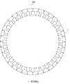
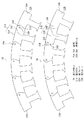
図1はこの発明の実施の形態1における積層鉄心1からなる回転電機の固定子鉄心100の構成を示す平面図、図2は積層鉄心1の構成を示す平面図、図3は積層鉄心1を形成する第1コア部材2Aと第2コア部材2Bの構成を示す平面図、図4は図2の積層鉄心1のX−X線に沿う部分断面図であり、隣接するコア片の連結部分を示す。
図1に示すように、回転電機の固定子鉄心100は、複数の積層鉄心1(ここでは6個)を環状に配置して形成されている。
Embodiment 1 FIG.
FIG. 1 is a plan view showing a configuration of a
As shown in FIG. 1, a
このような積層鉄心1は、図2〜図4に示すように、複数の第1コア片21Aを連続的に配列してなる第1コアシート22Aを1枚又は複数枚重ねて形成される第1コア部材2Aと、複数の第2コア片21Bを連続的に配列してなる第2コアシート22Bを1枚又は複数枚重ねて形成される第2コア部材2Bとが交互に積層されることにより形成されている。なお、図2は、図3に示す第1コア部材2Aと第2コア部材2Bとを積層して形成した積層鉄心1の平面図であり、図面上には積層方向上端側に配置される第1コア部材2Aが見えている。
As shown in FIGS. 2 to 4, such a laminated core 1 is formed by stacking one or a plurality of first core sheets 22 </ b> A formed by continuously arranging a plurality of
第1コア片21Aはバックヨーク部23Aとバックヨーク部23Aの中央部から突出したティース部24Aとを備え、バックヨーク部23Aの一方側の縁部25A(図3中右側)の表面には連結手段26Aとしての凹部260Aが形成され、裏面には連結手段26Aとしての凸部261Aが形成されている。そして、縁部25Aの端面27Aは略凸円弧状に形成され、他方側の端面28Aは一方側の端面27Aと係合する略凹円弧状に形成されている。
このような第1コア片21Aを6個使用し、バックヨーク部23Aの各端面27A、28Aを介して連続的に配列することにより第1コアシート22Aは構成されている。第1コアシート22Aの両端となる第1コア片21Aの端面29Aは直線状に形成され、積層鉄心1の端部11を形成している。
The
The
第2コア片21Bは第1コア片21Aとほぼ同様の構成であるが、連結手段26Bの配置が第1コア片21Aの場合とは逆である。すなわち、第2コア片21Bはバックヨーク部23Bとティース部24Bとを備え、連結手段26Bとしての凹部260Bおよび凸部261Bはバックヨーク部23Bの他方側の縁部25B(図3中左側)に設けられている。凹部260Bは縁部25Bの表面に、凸部261Bは縁部25Bの裏面に設けられている。そして、縁部25Bの端面27Bは略凸円弧状に形成され、一方側の端面28Bは他方側の端面27Bと係合する略凹円弧状に形成されている。
このような第2コア片21Bを6個使用し、バックヨーク部23Bの各端面27B、28Bを介して連続的に配列することにより第2コアシート22Bは構成されている。第2コアシート22Bの両端となる第2コア片21Bの端面29Bは直線状に形成され、積層鉄心1の端部11を形成している。
The second core piece 21B has substantially the same configuration as the
The
積層鉄心1は、第1コア部材2Aと第2コア部材2Bとが交互に積層されることにより形成されるが、その際、第1コア部材2Aの各第1コア片21A間の位置(すなわち第1コア片21Aの端面27A、28A間の位置)と、第2コア部材2Bの各第2コア片21B間の位置(すなわち第2コア片21Bの端面27B、28B間の位置)とが長手方向にずらされ、第1コア片21Aと第2コア片21Bとの積層方向に相隣る縁部25A、25B同士が重なり合うように交互に積層される。
そして、第1コア片21Aと第2コア片21Bとの重なり合う縁部25A、25Bに設けられた凹部260Aと凸部261Bとが、または凸部261Aと凹部260Bとが嵌合されることにより、縁部25A、25B同士が回動自在に連結される。すなわち、積層方向に相隣る第1コア片21Aと第2コア片21Bとが連結手段26A、26Bにより回動自在に連結される。
なお、各第1、第2コア片21A、21Bのティース部24A、24Bの表裏面には、図示しない結合用凹凸部が設けられており、積層方向上下の各コア片21A、21Bの凹凸部を嵌め合うことで積層方向の固着を行っている。
また、複数枚の第1コアシート22Aから形成される第1コア部材2Aでは、連結手段26Aとして設けられた凹部260A、凸部261Aを上下で嵌合させることで、第1コア部材2A内の第1コア片21A同士の積層方向間の固着を図っている。同様に複数枚の第2コアシート22Bから形成される第2コア部材2Bでは、連結手段26Bとして設けられた凹部260Bと凸部261Bを上下で嵌合させることで、第2コア部材2B内の第2コア片21B同士の積層方向間の固着を図っている。
The laminated core 1 is formed by alternately laminating the
Then, the
In addition, on the front and back surfaces of the
Further, in the
積層鉄心1を構成する第1、第2コア部材2A、2Bをそれぞれ形成する第1、第2コアシート22A、22Bの枚数は、各コア部材2A、2Bの積層位置によって異なる箇所がある。本実施の形態1では、積層方向上側から3枚の第1コアシート22Aを重ねた第1コア部材2A、3枚の第2コアシート22Bを重ねた第2コア部材2B、1枚の第1コアシート22Aからなる第1コア部材2A、1枚の第2コアシート22Bからなる第2コア部材2B、1枚の第1コアシート22Aからなる第1コア部材2A、1枚の第2コアシート22Bからなる第2コア部材2B、3枚の第1コアシート22Aを重ねた第1コア部材2A、3枚の第2コアシート22Bを重ねた第2コア部材2Bにより積層鉄心1が形成されている。
The number of the first and
このように構成される積層鉄心1を6個使用し、これらの積層鉄心1の連結手段26A、26Bを回動させて環状に配置し、隣接する積層鉄心1の端部11同士を溶接等により接合して固定子鉄心100が形成される。
なお、積層鉄心1を構成する第1、第2コア部材2A、2Bの積層数、第1、第2コア部材2A、2Bを構成する第1、第2コアシート22A、22Bの枚数、第1、第2コアシート22A、22Bを構成する第1、第2コア片21A、21Bの数は上記構成に限られるものではなく、また、固定子鉄心100を構成する積層鉄心1の数や、ティース部24の数もこれに限られるものではない。
また、本実施の形態1では連結手段26A、26Bは、凹部260Aと凸部261Bとの嵌合、または凸部261Aと凹部260Bとの嵌合による構成としたが、これに限られるものではなく、例えば縁部25A、25Bに貫通孔を設けこの貫通孔にピン部材を挿入することにより連結する構成としてもよい。
Six laminated iron cores 1 configured in this way are used, the connecting means 26A and 26B of these laminated iron cores 1 are rotated and arranged in an annular shape, and the end portions 11 of the adjacent laminated iron cores 1 are welded together. The
In addition, the number of first and
In the first embodiment, the connecting means 26A and 26B are configured by fitting the
ここで、形成する第1、第2コアシート22A、22Bの枚数が多い第1、第2コア部材2A、2Bが配置される箇所では、枚数が少ない第1、第2コア部材2A、2Bが配置される場合に比べて、第1コア片21Aと第2コア片21Bとを連結手段26A、26Bにて回動させる際の積層間の摩擦が減少し、積層鉄心1を変形させる際に必要なトルクを小さくすることができ、組立作業性を向上させることができる。
また、第1コア片21Aと第2コア片21Bとの重なり合う縁部25A、25Bにおいては磁路が積層方向にも形成されるため、第1、第2コアシート22A、22Bの枚数が少ない第1、第2コア部材2A、2Bが配置される箇所では、コアシート22A、22Bの枚数が多い第1、第2コア部材2A、2Bが配置される箇所に比べて磁路抵抗の増加が抑制され、磁気性能を向上させることができる。
本実施の形態1の積層鉄心1は、積層鉄心1を構成する全ての第1、第2コア部材2A、2Bを同一枚数の第1、第2コアシート22A、22Bから構成するのではなく、各コア部材2A、2Bの積層位置によって各コア部材2A、2Bを構成する第1、第2コアシート22A、22Bの枚数が異なる箇所があるため、各コア部材2A、2Bを構成する第1、第2コアシート22A、22Bの枚数が多い場合と少ない場合の双方の効果を得ることができ、連結手段による第1、第2コア片21A、21Bの回動時の摩擦を抑制して積層鉄心の組立作業性を向上させるとともに、磁路抵抗を低減して磁気特性の高い積層鉄心を得ることができる。
Here, in the place where the first and
In addition, since the magnetic paths are also formed in the stacking direction at the overlapping
The laminated iron core 1 according to the first embodiment does not constitute all the first and
特に本実施の形態1では、積層鉄心1の積層方向上下端側に配置される第1、第2コア部材2A、2Bを形成する第1、第2コアシート22A、22Bの枚数を多くしたため(ここでは3枚)、積層間の割れや剥がれにより積層隙間が生じやすい上下端側の第1、第2コア片21A、21Bにおいて、回動時の摩擦を小さくして積層隙間の発生を抑制することができる。これにより積層鉄心1の歪みを低減し寸法精度を向上させることができる。
また、積層鉄心1の寸法精度が向上するため端部11にズレや歪みが生じることを防止できる。これにより、固定子鉄心100を形成する際、隣接する積層鉄心1の端部11同士を確実に突き合わせることができ、端部11同士を溶接等により連結する時の作業性改善や溶接強度の向上を図ることができる。
Particularly in the first embodiment, the number of the first and
Further, since the dimensional accuracy of the laminated core 1 is improved, it is possible to prevent the end 11 from being displaced or distorted. Thereby, when forming the
また、本実施の形態1では、積層鉄心1の積層方向中央部に配置される第1、第2コア部材2A、2Bを形成する第1、第2コアシート22A、22Bの枚数を少なくしている(ここでは1枚)。積層鉄心1は、積層方向上下端側で磁束が漏れやすく、積層方向上下端よりも中央側の方が磁束量が増える。本実施の形態1の構成は、磁束量の多い積層鉄心1の積層方向中央部において磁束を効率よく利用でき、より磁気性能を向上させることができる。そして、磁束が漏れる積層鉄心1の上下端側では回動時の摩擦の減少を図ることができる。
In the first embodiment, the number of the first and
実施の形態2.
図5はこの発明の実施の形態2における積層鉄心10からなる回転電機の固定子鉄心110の構成を示す平面図、図6は積層鉄心10を展開した状態を示す平面図であり、図7は図5の積層鉄心10のY−Y線に沿う部分断面図であり、隣接するコア片の連結部分を示す。
実施の形態1では6個の積層鉄心1を環状に配置することにより固定子鉄心100を構成していたが、本実施の形態2では1個の積層鉄心10により固定子鉄心110を構成している。また、第1、第2コア部材20A、20Bを構成する第1、第2コアシート220A、220Bの枚数、および第1、第2コアシート220A、220Bを構成する第1、第2コア片21A、21Bの個数が実施の形態1とは異なっている。なお、上記実施の形態1と同様の構成については同一符号を付して説明を省略する。
Embodiment 2. FIG.
FIG. 5 is a plan view showing a configuration of a
In the first embodiment, the
積層鉄心10は、9個の第1、第2コア片21A、21Bを連続的に配列して構成された第1、第2コアシート220A、220Bから形成される第1、第2コア部材20A、20Bを交互に積層して構成されている。
そして、積層鉄心10は積層方向上側から5枚の第1コアシート220Aを重ねた第1コア部材20A、3枚の第2コアシート220Bを重ねた第2コア部材20B、1枚の第1コアシート220Aからなる第1コア部材20A、1枚の第2コアシート220Bからなる第2コア部材20B、1枚の第1コアシート220Aからなる第1コア部材20A、1枚の第2コアシート220Bからなる第2コア部材20B、2枚の第1コアシート220Aを重ねた第1コア部材20A、3枚の第2コアシート220Bを重ねた第2コア部材20Bにより形成されている。
The
The
上記実施の形態1で記載の通り、積層方向上下端側では積層間の割れや剥がれにより積層隙間が生じやすいが、上端側と下端側を比較すると、下端側は割れや剥がれが生じても上に積み重なった第1、第2コア片21A、21Bの荷重により加圧され積層隙間の発生が軽減され、上端側は積層隙間の発生が著しい。そして、上端側に積層隙間が発生すると再度加圧する等の手直し作業が必要となり作業性が悪くなる。
本実施の形態2の積層鉄心10は、積層方向上端側に配置される第1コア部材20Aを形成するコアシート220Aの枚数(ここでは5枚)が、積層方向下端側に配置される第2のコア部材20Bを形成するコアシート220Bの枚数(ここでは3枚)よりも多いので、上記実施の形態1の効果に加え、積層隙間がより発生しやすい上端側での積層隙間の発生をより抑制し、手直し作業をなくして生産性を向上できる。
As described in Embodiment 1, the upper and lower ends in the stacking direction are likely to cause stacking gaps due to cracks or peeling between the stacks. However, when the upper end side and the lower end side are compared, the lower end side may be cracked or peeled off. Is pressed by the load of the first and
In the
また、本実施の形態2では固定子鉄心110は1個の積層鉄心10を一円にして構成されているため歪みが一箇所に片寄って表れ、実施の形態1の場合よりも積層鉄心10の端部11の歪みやズレが顕著である。しかし、積層方向上下端側に配置される第1、第2コア部材20A、20Bを形成する第1、第2コアシート220A、220Bの枚数を多くすることによる積層鉄心10の寸法精度の向上により、端部11の歪みやズレを防止することができる。これにより端部11同士をきれいに揃えて突き合わせることができ、端部11同士を溶接等により連結する際の作業性改善や溶接強度の向上を図ることができる。
Further, in the second embodiment, the
なお、積層鉄心10を構成する第1、第2コア部材20A、20Bの積層数、第1、第2コア部材20A、20Bを構成する第1、第2コアシート220A、220Bの枚数、第1、第2コアシート220A、220Bを構成する第1、第2コア片21A、21Bの数は上記構成に限られるものではなく、また、固定子鉄心110を構成するティース部24の数もこれに限られるものではない。
In addition, the number of first and
1,10 積層鉄心、2A 第1コア部材、2B 第2コア部材、
20A 第1コア部材、20B 第2コア部材、21A 第1コア片、
21B 第2コア片、22A 第1コアシート、22B 第2コアシート、
25A,25B 縁部、26,26A,26B 連結手段、220A 第1コアシート、
220B 第2コアシート、260A,260B 凹部、261A,261B 凸部。
1,10 laminated iron core, 2A first core member, 2B second core member,
20A 1st core member, 20B 2nd core member, 21A 1st core piece,
21B 2nd core piece, 22A 1st core sheet, 22B 2nd core sheet,
25A, 25B edge, 26, 26A, 26B connecting means, 220A first core sheet,
220B 2nd core sheet, 260A, 260B recessed part, 261A, 261B Convex part.
Claims (3)
上記第1、第2コア片の重なり合う縁部に上記縁部同士を回動自在に連結する連結手段を備え、
上記第1、第2の各コア部材を形成する上記第1、第2コアシートの枚数は、上記各コア部材の積層位置によって異なる箇所があり、
更に上記第1、第2の各コア部材のうち、積層方向上下端側に配置されるコア部材を形成する上記第1、第2コアシートの枚数は、積層方向中央部に配置されるコア部材を形成する上記第1、第2コアシートの枚数よりも多いことを特徴とする積層鉄心。 A first core member formed by stacking one or more first core sheets formed by continuously arranging a plurality of plate-like first core pieces, and a plurality of plate-like second core pieces continuously. And a second core member formed by stacking one or more second core sheets arranged in a plurality of positions, the positions between the first core pieces of the first core member and the second core members. The position between the core pieces is shifted in the longitudinal direction, and the adjacent edges in the stacking direction of the first core pieces and the second core pieces are alternately stacked,
A connecting means for rotatably connecting the edges to the overlapping edges of the first and second core pieces;
The number of the first and second core sheets forming the first and second core members is different depending on the lamination position of the core members ,
Further, among the first and second core members, the number of the first and second core sheets forming the core member disposed on the upper and lower ends in the stacking direction is the core member disposed in the center in the stacking direction. A laminated iron core characterized in that there are more than the number of the first and second core sheets forming the core.
Priority Applications (1)
| Application Number | Priority Date | Filing Date | Title |
|---|---|---|---|
| JP2011171076A JP5660993B2 (en) | 2011-08-04 | 2011-08-04 | Laminated iron core |
Applications Claiming Priority (1)
| Application Number | Priority Date | Filing Date | Title |
|---|---|---|---|
| JP2011171076A JP5660993B2 (en) | 2011-08-04 | 2011-08-04 | Laminated iron core |
Publications (3)
| Publication Number | Publication Date |
|---|---|
| JP2013038853A JP2013038853A (en) | 2013-02-21 |
| JP2013038853A5 JP2013038853A5 (en) | 2013-11-14 |
| JP5660993B2 true JP5660993B2 (en) | 2015-01-28 |
Family
ID=47887939
Family Applications (1)
| Application Number | Title | Priority Date | Filing Date |
|---|---|---|---|
| JP2011171076A Active JP5660993B2 (en) | 2011-08-04 | 2011-08-04 | Laminated iron core |
Country Status (1)
| Country | Link |
|---|---|
| JP (1) | JP5660993B2 (en) |
Families Citing this family (1)
| Publication number | Priority date | Publication date | Assignee | Title |
|---|---|---|---|---|
| JP6221360B2 (en) * | 2013-06-05 | 2017-11-01 | 株式会社ジェイテクト | Stator |
Family Cites Families (4)
| Publication number | Priority date | Publication date | Assignee | Title |
|---|---|---|---|---|
| JP3279279B2 (en) * | 1998-06-30 | 2002-04-30 | 三菱電機株式会社 | Iron core equipment |
| JP3943338B2 (en) * | 2001-02-02 | 2007-07-11 | 三菱電機株式会社 | Iron core material |
| JP4027132B2 (en) * | 2002-03-19 | 2007-12-26 | 三菱電機株式会社 | Iron core device, method for manufacturing iron core device, permanent magnet motor and hermetic compressor |
| JP5237720B2 (en) * | 2008-08-08 | 2013-07-17 | 三菱電機株式会社 | Laminated fixed iron core |
-
2011
- 2011-08-04 JP JP2011171076A patent/JP5660993B2/en active Active
Also Published As
| Publication number | Publication date |
|---|---|
| JP2013038853A (en) | 2013-02-21 |
Similar Documents
| Publication | Publication Date | Title |
|---|---|---|
| JP5896937B2 (en) | Divided iron core, stator using the divided iron core, and rotating electric machine equipped with the stator | |
| JP6653560B2 (en) | Stator laminated iron core and method of manufacturing the same | |
| JP6334738B2 (en) | Rotating electric machine | |
| JP5971418B2 (en) | Synchronous rotor for rotating electrical machine and method for manufacturing synchronized rotor for rotating electrical machine | |
| JP4730461B2 (en) | Magnetic core manufacturing method | |
| JP6649676B2 (en) | Manufacturing method of laminated core | |
| JP4709114B2 (en) | Stator for rotating electrical machine | |
| JP5609619B2 (en) | Rotating electric machine stator core | |
| JP2019016645A (en) | Reactor and manufacturing method of core body | |
| JP6588504B2 (en) | Reactor with outer peripheral core and core coil | |
| JPWO2019111777A1 (en) | Manufacturing method of stator core and stator core | |
| JP5660993B2 (en) | Laminated iron core | |
| JP6723209B2 (en) | Inner iron transformer core | |
| WO2014115271A1 (en) | Stator core and electric motor | |
| JP2010041893A (en) | Laminated fixed core | |
| CN203456956U (en) | Excitation stator lamination and excitation stator core | |
| EP3723241B1 (en) | Rotor core for rotating electric machine and method for manufacturing rotor core for rotating electric machine | |
| JP2016082627A (en) | Stator for rotary electric machine | |
| JP2009095189A (en) | Split stator and motor | |
| JP3189478U (en) | Assembly structure of steel core | |
| JP5738167B2 (en) | Laminated iron core | |
| JP6942205B2 (en) | Stator and motor | |
| JP2013070494A (en) | Stator core and motor | |
| JP2020072211A (en) | Laminated iron core for stationary induction equipment | |
| CN210668035U (en) | Electric reactor |
Legal Events
| Date | Code | Title | Description |
|---|---|---|---|
| A521 | Request for written amendment filed |
Free format text: JAPANESE INTERMEDIATE CODE: A523 Effective date: 20131001 |
|
| A621 | Written request for application examination |
Free format text: JAPANESE INTERMEDIATE CODE: A621 Effective date: 20131001 |
|
| A977 | Report on retrieval |
Free format text: JAPANESE INTERMEDIATE CODE: A971007 Effective date: 20140820 |
|
| A131 | Notification of reasons for refusal |
Free format text: JAPANESE INTERMEDIATE CODE: A131 Effective date: 20140826 |
|
| A521 | Request for written amendment filed |
Free format text: JAPANESE INTERMEDIATE CODE: A523 Effective date: 20140911 |
|
| TRDD | Decision of grant or rejection written | ||
| A01 | Written decision to grant a patent or to grant a registration (utility model) |
Free format text: JAPANESE INTERMEDIATE CODE: A01 Effective date: 20141104 |
|
| A61 | First payment of annual fees (during grant procedure) |
Free format text: JAPANESE INTERMEDIATE CODE: A61 Effective date: 20141202 |
|
| R150 | Certificate of patent or registration of utility model |
Ref document number: 5660993 Country of ref document: JP Free format text: JAPANESE INTERMEDIATE CODE: R150 |
|
| R250 | Receipt of annual fees |
Free format text: JAPANESE INTERMEDIATE CODE: R250 |
|
| R250 | Receipt of annual fees |
Free format text: JAPANESE INTERMEDIATE CODE: R250 |
|
| R250 | Receipt of annual fees |
Free format text: JAPANESE INTERMEDIATE CODE: R250 |
|
| R250 | Receipt of annual fees |
Free format text: JAPANESE INTERMEDIATE CODE: R250 |
|
| R250 | Receipt of annual fees |
Free format text: JAPANESE INTERMEDIATE CODE: R250 |
|
| R250 | Receipt of annual fees |
Free format text: JAPANESE INTERMEDIATE CODE: R250 |
|
| R250 | Receipt of annual fees |
Free format text: JAPANESE INTERMEDIATE CODE: R250 |