JP4023533B2 - Bag supply device for packaging machine - Google Patents
Bag supply device for packaging machine Download PDFInfo
- Publication number
- JP4023533B2 JP4023533B2 JP2002098122A JP2002098122A JP4023533B2 JP 4023533 B2 JP4023533 B2 JP 4023533B2 JP 2002098122 A JP2002098122 A JP 2002098122A JP 2002098122 A JP2002098122 A JP 2002098122A JP 4023533 B2 JP4023533 B2 JP 4023533B2
- Authority
- JP
- Japan
- Prior art keywords
- liquid
- endless belt
- supported
- base
- top plate
- Prior art date
- Legal status (The legal status is an assumption and is not a legal conclusion. Google has not performed a legal analysis and makes no representation as to the accuracy of the status listed.)
- Expired - Lifetime
Links
Images


Description
【0001】
【発明の属する技術分野】
本発明は、液体注出用口金を装備する多数の包袋を縦列状態に包装機に対して運搬供給する装置に関する。
【0002】
【発明が解決しようとする課題】
多数の包袋を包装機に対し搬送供給する場合、一般的には例えば特開平5−42107号公報に開示し且つ図6に示すごとく、エンドレス丸ベルト2上に鎧重ね状に搭載した多数の包袋1を、両サイドのガイド壁3に沿い包装機に向けて運搬する構造を採用する。例えばスポーツドリンクを封入するプラステイック製の包袋は、その一部に前記液体を注出するためのノズルつまりプラスチック製の口金を装備する。このため前記運搬装置を採用する場合、図7に示すごとく丸ベルト2の搬送力を受ける下側の包袋1bの口金4bが強引に、上側の包袋1aの口金4aの下に潜り込んで、上側の包袋1aを横ずれさせるという問題がある。
【0003】
例えば特開2002−53101に示すように、連続的に引き出される帯状フイルムを2つ折りして製袋化しながら各包袋に前記口金を順次取付け、同口金を通して各包袋の内部にドリンクを充填する工程を一元化している大手企業では、この種包袋にドリンクを封入して製品化することに何らの問題も起こらない。元々この種包袋は、前記のごとく大手業者が液封入の無人化ため開発したものであるから、小規模の業者がこの種の包袋を使用し、例えば石鹸液などを包装して商品化する場合は、作業員が包袋を1枚ずつロータリ包装機に対して手渡しする状態で非常に手間がかかるという問題が生ずる。そこで本発明はこの種の包袋の手渡しを排除し、機械的に前記包袋の包装機への供給を可能にすることを目的とするものである、
【0004】
【その解決手段】
本発明は前記目的のために、位置規制用のストッパに向け、両側のガイド壁の間で、エンドレスベルト上に鎧重ね状に搭載した多数の包袋を運搬する装置であり、前記各包袋に固定し且つ1連に配置した液体注出用口金の移動域上部に、前記口金の上方への遊び動きを規制する天板を設置して構成したもので、後続からの包袋の競り込みがあっても、天板は口金の上方への遊び動きを規制するため、前後の口金が重なることはなく、各包袋は規則正しく縦列移動する。
両側ガイド壁の内側において包袋側縁を下側から支持するスライドプレートの上域に、前記包袋側縁の上方への反り曲がりを規制する押さえガイドを設置するので、包袋の横ずれはなくなり、包袋の縦列移動はより確実化する。
【0005】
【発明の実施形態】
図1に示す側面図の矢印断面は図2に示し、前図の平面は図3に示し、搬送する包袋は図4に示すごとくである。これら図面に示すように両側板10の内部それぞれに固定する軸受11に、2個のプーリ12を固定する軸13を回転自在に支持すると共に、前記各プーリに支持した丸ベルト14は多数の包袋15を鎧重ね状に搭載する。前記側板10れぞれの上端を折り曲げ形成した垂直のガイド壁21と、同ガイド壁の下縁に水平なスライド面22を両サイドに形成し、前記包袋15の両側縁の荷重を前記スライド面22で支える。前記包袋15は図4のごとく片側よりに、ブラステイック製のノズル18及び、同ねじ付きキヤップ19とからなる口金20を装備し、各口金20を同一方向に連ねて配置し、モータ16の回転動力をタイミングベルト17を介し前記丸ベルト17に伝えて前記包袋15を搬送する。
【0006】
図2における左側の側板10に、複数のビス23を用いて断面L字型の天板24を支持するが、当該天板24はスライド面22との間で、包袋の口金20が上下方向に必要以上に遊び動くのを規制するのが目的で、また同右側板10にビス25を用いて設置する断面コの字形の押さえガイド26は、スライド面22との間で包袋15側縁の反り曲りを防止し、包袋15の横ずれを防ぐ目的であって、これら両要素の設置により各包袋は整列正しく運搬されるのである。
【0007】
図1における丸ベルト14のエンド部から、包袋15の移動方向に向けて滑走板30を設置すると共に、前記滑走板30の上面端部に断面L字型のストッパ31を設置し、搬送する包袋15を当該ストッパ31で受け止め、ロット32の矢印33方向への往復運動で、ピン34を軸に上下に揺動するレバー35先端の真空カップ36は、ストッパ31に衝突して停止する包袋15を1枚づつ抜きとって包装機に供給するが、滑走板30のポート37から覗くセンサー38は、前記真空カップ36による包袋15排除により上方に空間が生ずる度に、制御器39を介してモータ16に信号40を送信するので、モータ16は最前の包袋15が前記ポート37を所定の時間間隔で塞ぐ角度だけ断続運転する。
【0008】
図3において天板24は、それに形成する水平方向への長穴にビス23を通して側板10に固定する。従って前記ビス23を緩め、前記天板24を包袋15の移送方向に沿って変位し、同天板24の端とストッパ31との間の、包袋抜き取り間隔41を任意に調整可能であり、一方押さえガイド26も、それに形成する水平方向への長穴にビス25を通して側板10に固定する。従って前記ビス25を緩め、前記押さえガイド26を包袋15の移送方向に沿って変位し、同押さえガイド26の端とストッパ31との間の、包袋抜き取り間隔41を任意に調整可能である。
【0001】
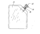
図5に示す包袋15はそのセンターに液注出用の口金20を備えるので、スライドプレート50との間で前記口金20の上下方向への遊び動きを規制する天板45を、図示を省略するが適当な二股材を介して両側板10に、包袋15の搬送方向に変位調整自在に支持する。この場合は両側において一対の押さえガイド26が包袋両側縁の反り曲がりを規制する。なお同図でのその他符号で示す構成要素は、図2の同符号が示す構成要素と同一である。
【図面の簡単な説明】
【図1】 側面図
【図2】 前図におけるII− II線断面図
【図3】 前図の平面図
【図4】 包袋の説明図
【図5】 他の実施形態の説明図
【図6】 従来構成の説明図
【図7】 従来構成の説明図
【符号の説明】
10…側板
14…丸ベルト
15…包袋
20…キヤップ
21…壁板
22…スライド面
23、25…ビス
24…天板
26…押さえガイド
30…滑走板
31…ストッパ
35…レバー
36…真空カツプ
38…センサー
39…制御器[0001]
BACKGROUND OF THE INVENTION
The present invention relates to an apparatus for transporting and supplying a large number of sachets equipped with a liquid dispensing base to a packaging machine in a tandem state.
[0002]
[Problems to be solved by the invention]
When a large number of wrapping bags are conveyed and supplied to a packaging machine, generally, as disclosed in, for example, Japanese Patent Application Laid-Open No. 5-42107 and shown in FIG. A structure in which the wrapping bag 1 is transported toward the packaging machine along the
[0003]
For example, as shown in Japanese Patent Laid-Open No. 2002-53101, the base film is sequentially attached to each wrapping bag while making a continuous fold-out strip-like film into a bag and filling the inside of each wrapping bag through the base. In a large company that unifies the process, there is no problem in putting a drink in this seed bag and commercializing it. Originally, this kind of sachet was developed by a major supplier for unmanned liquid filling as mentioned above, so small-scale traders use this kind of sachet and wrap it with soap liquid for commercialization. In such a case, there is a problem that it takes a lot of labor in a state where an operator hands over the packaging bags one by one to the rotary packaging machine. Therefore, the present invention aims to eliminate the handing of this type of wrapping bag and to enable mechanical supply of the wrapping bag to the packaging machine.
[0004]
[Solution]
For the above-mentioned purpose, the present invention is an apparatus for transporting a large number of wrapping bags mounted on an endless belt in an armor-stacked manner between guide walls on both sides toward a position regulating stopper, A top plate that restricts the upward movement of the base is installed on the upper part of the moving area of the liquid pouring base fixed to the base and placed in a row. Even if there is, the top plate restricts the upward movement of the base, so that the front and rear bases do not overlap, and each packing bag moves in a regular column.
A holding guide that regulates the upward bending of the side edge of the bag is installed in the upper area of the slide plate that supports the side edge of the bag from the lower side inside the guide walls on both sides. The tandem movement of the wrapping bag is more reliable.
[0005]
DETAILED DESCRIPTION OF THE INVENTION
1 is shown in FIG. 2, the plane of the previous figure is shown in FIG. 3, and the package to be conveyed is as shown in FIG. As shown in these drawings, a
[0006]
A top plate 24 having an L-shaped cross section is supported on the
[0007]
A
[0008]
In FIG. 3, the top plate 24 is fixed to the
[0001]
Since the
[Brief description of the drawings]
[Fig. 1] Side view [Fig. 2] II-II sectional view in the previous diagram [Fig. 3] Plan view of the previous diagram [Fig. 4] Explanatory diagram of the wrapping bag [Fig. 5] Explanatory diagram of the other embodiment [Fig. 6] Illustration of conventional configuration [FIG. 7] Illustration of conventional configuration [Explanation of symbols]
DESCRIPTION OF
Claims (3)
前記各包袋それぞれの進行方向側片側コーナの液体注出用口金を、下部の前記スライド面と、前記側板に支持する上部の天板とで支えて、同液体注出用口金の上方への遊び動きを規制する一方、前記液体注出用口金の反対側の包袋側縁を、前記下部のスライド面と、前記側板に支持する上部の押さえガイドとの間で支持して前記側縁の上方への反り曲がりを規制する状態に形成した供給装置。A horizontal slide surface with a downward drop is formed on each of the vertical guide walls inside the upper side plates on both sides, and liquid is poured onto the slide surfaces and the endless belt between the slide surfaces. A large number of sachets provided with bases are mounted in an armor stack so that the liquid pouring base is directed backwards in the direction of travel, and each sachet is transported in an armor stack by the rotational power of the endless belt Device to
Supporting the liquid dispensing base of the one side corner in the direction of travel of each wrapping bag with the lower slide surface and the upper top plate supported by the side plate, the upper part of the liquid dispensing base While restricting the play movement, the side edge of the wrapping bag opposite to the liquid dispensing base is supported between the lower slide surface and the upper pressing guide supported by the side plate. A supply device formed so as to restrict upward bending.
前記各包袋それぞれの進行方向中心の液体注出用口金を、前記複数列のエンドレスベルト間に設置したプレートと、その上部の天板との間で支えて、同液体注出用口金の上方への遊び動きを規制する一方、前記液体注出用口金の両側の包袋側縁を、両サイドの前記側板それぞれに支持する上部の押さえガイドと、その下部の前記スライド面との間で支持して前記側縁の上方への反り曲がりを規制する状態に形成した供給装置。A horizontal slide surface with a downward drop is formed on each of the vertical guide walls inside the upper side plates on both sides, and liquid is poured onto the slide surfaces and the endless belt between the slide surfaces. A large number of sachets provided with bases are mounted in an armor stack so that the liquid pouring base is directed backwards in the direction of travel, and each sachet is transported in an armor stack by the rotational power of the endless belt Device to
A liquid dispensing base at the center in the direction of travel of each sachet is supported between a plate installed between the plurality of rows of endless belts and a top plate on the top, and above the liquid dispensing base. while regulating the play movement of the support between the both sides of the wrapper side edge of the liquid pouring mouthpiece, and an upper retainer guide for supporting said side plates respectively on both sides, and the slide surface of the lower portion And the supply apparatus formed in the state which controls the curvature to the upper direction of the said side edge.
Priority Applications (1)
| Application Number | Priority Date | Filing Date | Title |
|---|---|---|---|
| JP2002098122A JP4023533B2 (en) | 2002-04-01 | 2002-04-01 | Bag supply device for packaging machine |
Applications Claiming Priority (1)
| Application Number | Priority Date | Filing Date | Title |
|---|---|---|---|
| JP2002098122A JP4023533B2 (en) | 2002-04-01 | 2002-04-01 | Bag supply device for packaging machine |
Publications (3)
| Publication Number | Publication Date |
|---|---|
| JP2003291922A JP2003291922A (en) | 2003-10-15 |
| JP2003291922A5 JP2003291922A5 (en) | 2005-09-02 |
| JP4023533B2 true JP4023533B2 (en) | 2007-12-19 |
Family
ID=29240267
Family Applications (1)
| Application Number | Title | Priority Date | Filing Date |
|---|---|---|---|
| JP2002098122A Expired - Lifetime JP4023533B2 (en) | 2002-04-01 | 2002-04-01 | Bag supply device for packaging machine |
Country Status (1)
| Country | Link |
|---|---|
| JP (1) | JP4023533B2 (en) |
Families Citing this family (2)
| Publication number | Priority date | Publication date | Assignee | Title |
|---|---|---|---|---|
| JP4555767B2 (en) * | 2005-01-31 | 2010-10-06 | 株式会社古川製作所 | Method and apparatus for supplying zippered bag |
| US10940657B2 (en) * | 2015-08-24 | 2021-03-09 | Kao Corporation | Pouch container aligned structure, manufacturing device for same, and manufacturing method for same |
-
2002
- 2002-04-01 JP JP2002098122A patent/JP4023533B2/en not_active Expired - Lifetime
Also Published As
| Publication number | Publication date |
|---|---|
| JP2003291922A (en) | 2003-10-15 |
Similar Documents
| Publication | Publication Date | Title |
|---|---|---|
| EP1897808B1 (en) | Device for packing items in a box, and a method for the same | |
| JP5237097B2 (en) | Conveying device and boxing device provided with the same | |
| JP2529721Y2 (en) | Packaging machine | |
| JP5878727B2 (en) | Packaging device | |
| JP6109509B2 (en) | Article alignment supply device | |
| JP2007112515A (en) | Apparatus for arranging small article packed to predetermined location in predetermined posture and sending and delivering article into cup in strip-like sheet | |
| JP4023533B2 (en) | Bag supply device for packaging machine | |
| JP5753643B2 (en) | Cardboard boxing system | |
| JP2015093731A (en) | Pillow packing machine | |
| JP5739637B2 (en) | Alignment method and transfer device | |
| JP2012232765A (en) | Bag feeder | |
| JP2004026444A (en) | Article aligning and conveying device | |
| JPH0648552A (en) | Reversal transfer device of material to be carried | |
| JP5184231B2 (en) | Method and apparatus for positioning and packaging multiple packages | |
| JP6938027B2 (en) | Integration device | |
| JP4159532B2 (en) | Supply device for packaging with cap | |
| GB2128162A (en) | A method of and apparatus for stacking and introducing flat articles into containers | |
| JP4638701B2 (en) | Method and apparatus for bagging and packaging sliced bread | |
| JP2008019085A (en) | Carrying device and boxing apparatus having it | |
| JP6025682B2 (en) | Device for supplying packaged products and accessories to automatic packaging machines | |
| JP2020040759A (en) | Article erecting device, article aligning and feeding device, and article erecting aligning and feeding device | |
| JPH0340724Y2 (en) | ||
| JP2010126310A (en) | Conveying device, and packaging device provided with the same at article conveying-in side | |
| JP5075797B2 (en) | Transport device | |
| JP2011143962A (en) | Carton carrying device |
Legal Events
| Date | Code | Title | Description |
|---|---|---|---|
| A521 | Request for written amendment filed |
Free format text: JAPANESE INTERMEDIATE CODE: A523 Effective date: 20050225 |
|
| A621 | Written request for application examination |
Free format text: JAPANESE INTERMEDIATE CODE: A621 Effective date: 20050225 |
|
| A977 | Report on retrieval |
Free format text: JAPANESE INTERMEDIATE CODE: A971007 Effective date: 20070427 |
|
| A131 | Notification of reasons for refusal |
Free format text: JAPANESE INTERMEDIATE CODE: A131 Effective date: 20070509 |
|
| A521 | Request for written amendment filed |
Free format text: JAPANESE INTERMEDIATE CODE: A523 Effective date: 20070514 |
|
| TRDD | Decision of grant or rejection written | ||
| A01 | Written decision to grant a patent or to grant a registration (utility model) |
Free format text: JAPANESE INTERMEDIATE CODE: A01 Effective date: 20070907 |
|
| A61 | First payment of annual fees (during grant procedure) |
Free format text: JAPANESE INTERMEDIATE CODE: A61 Effective date: 20070925 |
|
| R150 | Certificate of patent or registration of utility model |
Ref document number: 4023533 Country of ref document: JP Free format text: JAPANESE INTERMEDIATE CODE: R150 Free format text: JAPANESE INTERMEDIATE CODE: R150 |
|
| FPAY | Renewal fee payment (event date is renewal date of database) |
Free format text: PAYMENT UNTIL: 20101012 Year of fee payment: 3 |
|
| FPAY | Renewal fee payment (event date is renewal date of database) |
Free format text: PAYMENT UNTIL: 20111012 Year of fee payment: 4 |
|
| R250 | Receipt of annual fees |
Free format text: JAPANESE INTERMEDIATE CODE: R250 |
|
| FPAY | Renewal fee payment (event date is renewal date of database) |
Free format text: PAYMENT UNTIL: 20111012 Year of fee payment: 4 |
|
| FPAY | Renewal fee payment (event date is renewal date of database) |
Free format text: PAYMENT UNTIL: 20121012 Year of fee payment: 5 |
|
| R250 | Receipt of annual fees |
Free format text: JAPANESE INTERMEDIATE CODE: R250 |
|
| FPAY | Renewal fee payment (event date is renewal date of database) |
Free format text: PAYMENT UNTIL: 20121012 Year of fee payment: 5 |
|
| FPAY | Renewal fee payment (event date is renewal date of database) |
Free format text: PAYMENT UNTIL: 20131012 Year of fee payment: 6 |
|
| R250 | Receipt of annual fees |
Free format text: JAPANESE INTERMEDIATE CODE: R250 |
|
| R250 | Receipt of annual fees |
Free format text: JAPANESE INTERMEDIATE CODE: R250 |
|
| R250 | Receipt of annual fees |
Free format text: JAPANESE INTERMEDIATE CODE: R250 |
|
| R250 | Receipt of annual fees |
Free format text: JAPANESE INTERMEDIATE CODE: R250 |
|
| R250 | Receipt of annual fees |
Free format text: JAPANESE INTERMEDIATE CODE: R250 |
|
| R250 | Receipt of annual fees |
Free format text: JAPANESE INTERMEDIATE CODE: R250 |
|
| R250 | Receipt of annual fees |
Free format text: JAPANESE INTERMEDIATE CODE: R250 |
|
| R250 | Receipt of annual fees |
Free format text: JAPANESE INTERMEDIATE CODE: R250 |
|
| R250 | Receipt of annual fees |
Free format text: JAPANESE INTERMEDIATE CODE: R250 |
|
| R250 | Receipt of annual fees |
Free format text: JAPANESE INTERMEDIATE CODE: R250 |
|
| EXPY | Cancellation because of completion of term |