JP4019117B2 - Powder blowing apparatus and refining method - Google Patents
Powder blowing apparatus and refining method Download PDFInfo
- Publication number
- JP4019117B2 JP4019117B2 JP2002288116A JP2002288116A JP4019117B2 JP 4019117 B2 JP4019117 B2 JP 4019117B2 JP 2002288116 A JP2002288116 A JP 2002288116A JP 2002288116 A JP2002288116 A JP 2002288116A JP 4019117 B2 JP4019117 B2 JP 4019117B2
- Authority
- JP
- Japan
- Prior art keywords
- powder
- combustion
- fluid
- fuel
- supply pipe
- Prior art date
- Legal status (The legal status is an assumption and is not a legal conclusion. Google has not performed a legal analysis and makes no representation as to the accuracy of the status listed.)
- Expired - Lifetime
Links
Images


Classifications
-
- Y—GENERAL TAGGING OF NEW TECHNOLOGICAL DEVELOPMENTS; GENERAL TAGGING OF CROSS-SECTIONAL TECHNOLOGIES SPANNING OVER SEVERAL SECTIONS OF THE IPC; TECHNICAL SUBJECTS COVERED BY FORMER USPC CROSS-REFERENCE ART COLLECTIONS [XRACs] AND DIGESTS
- Y02—TECHNOLOGIES OR APPLICATIONS FOR MITIGATION OR ADAPTATION AGAINST CLIMATE CHANGE
- Y02P—CLIMATE CHANGE MITIGATION TECHNOLOGIES IN THE PRODUCTION OR PROCESSING OF GOODS
- Y02P10/00—Technologies related to metal processing
- Y02P10/20—Recycling
Description
【0001】
【発明の属する技術分野】
本発明は、溶融金属などの液体中に、コークス、廃棄物燃料等の粉体を、酸素、酸素富化空気等の流体とともに吹き込む装置および精錬方法に関する。
【0002】
【従来の技術】
液体中に粉体を気体や液体等の流体とともに吹き込む装置(以下、ランスと称する)は、様々な生産プロセスに用いられている。
特に、電気炉製鋼プロセスでは、溶融金属内にコークス等の粉状固体燃料(粉体)を、酸素とともに吹込み、燃焼させ、この燃焼エネルギーを溶融金属に着熱させることで、電力原単位を削減している。
また、精錬プロセスにおいても、溶融金属内に粉状のフラックスを吹込み、冶金反応促進・反応効率の向上が図られている。
これらのプロセスを効率的に行うためには、溶融金属内に粉体を深く浸入させる必要があり、そのためには粉体を高速で吹き込む必要がある。
従来、溶融金属内に粉体を吹き込む装置としては、非水冷型、および水冷型のランスが用いられている。
これらの装置は、高温の溶融金属や溶融スラグ中にランスを浸せきさせて、直接、溶融金属内に粉体を吹き込むことができる。
しかし、非水冷型ランスの場合には、ランス自体が溶損するため、これを頻繁に交換する必要があり、水冷型ランスの場合は、ノズル閉塞防止のため、頻繁にメンテナンスを行う必要がある。このため、いずれのランスにおいても、作業性に問題があった。
【0003】
一方、特許文献1、2には、ランスを高温の溶融金属や溶融スラグに浸せきすることなく、溶融金属から離れた位置から、超高速気体噴流を利用して粉体を搬送し噴出させることによって、粉体を高速で溶融金属等に吹き込むことができる装置が開示されている。
これらの装置では、ランスを溶融金属や溶融スラグに浸せきする必要がないために、ノズルのメンテナンスにかかるコストや作業性を大幅に改善できる。
しかし、特許文献3に記載された装置の場合には、粉体を気体噴流に混合させる位置が超高速噴流の噴出口から離れているため、混合位置において噴流自体が減速しており、また、気体噴流に対し、流れ方向が異なる粉体流を合流させるため、噴流に乱れが生じて噴流が大幅に減速してしまう。このため、粉体流の高速化が困難である。
また、特許文献4で開示された装置の場合には、気体噴流と粉体流とがほぼ同一方向で吹き込まれるため、噴流の乱れは少なくなるものの、この場合も、粉体と気体噴流との混合位置がノズルから離れているため、減速し始めた噴流に対して粉体を混合することとなり、粉体速度の高速化が困難であった。
【0004】
また、非特許文献1や特許文献5に記載されているようなランスも提案されている。
これらに開示された装置は、あらかじめ酸素に粉体を混合するか、または別系統で供給された酸素と粉体をスロート部直前で混合し、その混合流をラバールノズルから噴出させることができるようになっている。
この装置では、高速の酸素噴流と粉体が混合された状態でラバールノズルから噴出されるために、噴流および粉体の高速化が可能である。
この装置では、スロート部手前で高速の酸素噴流に粉体を混合するため、特にスロート部の摩耗が激しい。このため、ノズルが変形しやすく、超音速の噴流を噴出しにくくなることがあった。また、純酸素等の高濃度酸素富化流体を搬送流体として用いる場合には、可燃性粉体の搬送はできなかった。
この他に、特許文献6でもランスが提案されている。このランスは、粉体供給管の外周に酸素供給管を配置し、ノズル出口まで酸素と粉体を別系統で供給するものである。
この装置によれば、粉体供給によるノズル摩耗を防ぐことができる。
【0005】
【特許文献1】
米国特許第5,788,921号
【0006】
【特許文献2】
特開昭56−5914号公報
【0007】
【特許文献3】
米国特許第5,788,921号
【0008】
【特許文献4】
特開昭56−5914号公報
【0009】
【非特許文献1】
土井襄(編)、転炉製鋼法、日刊工業新聞社、p.192
【0010】
【特許文献5】
特開平8−81712号公報
【0011】
【特許文献6】
特開平7−216430号公報
【0012】
【発明が解決しようとする課題】
しかし、このノズルは高速の酸素噴流が、粉体流路を囲む円環状に形成されるため、粉体の飛散防止に効果的であるものの、粉体と酸素の混合位置がノズルから離れており、前述のように粉体流の高速化が困難であった。
また、粉体を高速の酸素噴流出口近傍に供給することができる装置も提案されているが、中心の粉体流を酸素噴流管の方向へ曲げるためのノズルが必要となり、粉体がこのノズルへ衝突し、ノズルが劣化する問題があった。
【0013】
また、鉄鋼精錬プロセスにおいては、高炉などで製造した溶鉄(例えば溶銑や、溶銑を脱炭して得られた溶鋼)に酸素を供給する酸化精錬が行われている。この際、種々の副原料が添加されることがある。
例えば溶湯の昇温や鉄スクラップの溶解などには炭材などの熱補償材が用いられる。不純物除去にはCaOなどの精錬材が用いられる。最終製品の材料特性上必要とされる成分の添加には合金類が用いられる。還元処理を行う際には鉄鉱石、マンガン鉱石などが用いられる。
溶鉄に副原料を添加する方法としては、上方から添加する方法と、浴中に添加する方法があるが、上方添加の場合には溶解性や投入効率などの問題があり、浴中添加の場合には設備的に添加が難しくなることがあった。
近年では、粉体化した副原料を酸素ランスを用いて上方から添加することが行われている。この方法では、直径数mm以下の細かい粒子の添加が可能となるため、副原料の溶解性、反応性を高めることができる。また装置を浴中に浸漬させる必要がないため設備的問題も解消される。
しかし、粉体の吹込みの際には、吹込み速度が不足し、粉体が飛散したり、浴中での粉体の混合が不十分となる問題があった。
本発明は、上記事情に鑑みてなされたもので、粉体の流速を高め、この粉体を効率よく液体に吹き込むことができる装置を提供することを目的とする。
【0014】
【課題を解決するための手段】
本発明の粉体吹込み装置は、液体中に粉体を吹き込む装置であって、粉体を供給する粉体供給管の外周側に、支燃性流体を供給する支燃性流体供給管が設けられた多重管構造のノズルを有し、これら供給管の隙間が支燃性流体流路とされ、粉体供給管と支燃性流体供給管の先端部には、支燃性流体流路が先端方向に向けて徐々に広くなるように形成されたテーパ部が設けられ、これらテーパ部より基端側に、前記隙間が比較的狭いスロート部が形成されていることを特徴とする。供給管中心軸に対するテーパ部の傾斜角度は、4〜11°が好ましく、更には5〜10°が好ましい。
スロート部における支燃性流体流路の断面積A1と、供給管の先端における支燃性流体流路の断面積A2との比率(A2/A1)は、次式で表される範囲内であることが好ましい。
【数2】

本発明の粉体吹込み装置は、支燃性流体供給管に、燃料流体流路から支燃性流体供給管内部に燃料流体を導く燃料流体噴出部が形成され、供給管中心軸に対する燃料流体噴出部の傾斜角度θ3が、5〜90°である構成とすることができる。
本発明の粉体吹込み装置は、燃料流体噴出部より先端側の支燃性流体供給管の内面に、周方向に沿う溝が形成されている構成とすることができる。
本発明の粉体吹込み装置では、支燃性流体供給管の燃料流体噴出部より先端側に、ほぼ一定の内径を有する直胴部が形成されている構成とすることができる。
【0015】
本発明の冷鉄源の溶解・精錬炉の操業方法は、粉体吹込み装置を用いて、酸素を含む支燃性流体と粉体とを、燃料流体とともに冷鉄源に向けて噴出させることによって、冷鉄源を溶解し、精錬する炉の操業方法であって、冷鉄源が溶解する溶解工程と、冷鉄源が溶落ちした後の精錬工程とにおいて、それぞれ独立に燃料流体供給量を設定することを特徴とする。
本発明の冷鉄源の溶解・精錬炉の操業方法では、上記粉体吹込み装置を用いることができる。
本発明の冷鉄源の溶解・精錬炉の操業方法は、脱珪、脱燐、脱硫、脱炭、昇温、熱付加、スクラップ溶解、合金溶解、還元処理、脱ガスのうち1種以上を対象とすることができる。
精錬にあたっては、固体炭素源、炭化水素源、石灰源、マグネシウム源、アルミニウム源、鉄鉱石、マンガン鉱石、合金のうち1種以上を溶鉄に添加することができる。
支燃性流体としては、純酸素ガス、工業用酸素ガス、空気のうち1種または2種以上を用いることができる。
【0016】
本発明の精錬方法は、粉体吹込み装置を用いて、粉体を供給するとともに、この粉体流の周囲から粉体を巻き込むように支燃性流体を供給し、これら粉体および支燃性流体を溶鉄に向けて噴出させることによって、この溶鉄を精錬することを特徴とする。
支燃性流体を噴出させる際の支燃性流体の初速は音速以上、好ましくはマッハ数M≧1.10とするのが好ましい。
本発明の精錬方法では、支燃性流体の周囲に燃料流体を噴出させ、この燃料流体を燃焼しつつ噴出させるのが好ましい。
本発明の精錬方法では、上記粉体吹込み装置を用いることができる。
本発明の精錬方法は、脱珪、脱燐、脱硫、脱炭、昇温、熱付加、スクラップ溶解、合金溶解、還元処理、脱ガスのうち1種以上を対象とすることができる。
精錬にあたっては、固体炭素源、炭化水素源、石灰源、マグネシウム源、アルミニウム源、鉄鉱石、マンガン鉱石、合金のうち1種以上を溶鉄に添加することができる。
支燃性流体としては、純酸素ガス、工業用酸素ガス、空気のうち1種または2種以上を用いることができる。
本発明の精錬方法では、精錬の際に発生する排ガスから顕熱または潜熱を回収することができる。
【0017】
【発明の実施の形態】
図1は、本発明の粉体吹込み装置の第1の実施形態の要部を示す概略構成図である。
図1に示す粉体吹込み装置(以下、ランスと称する)1は、溶融金属などの液体中に、コークス、廃棄物燃料等の粉体を吹き込むノズル2を備えている。
ここに示すノズル2は、コークスや廃棄物燃料等の粉体を空気等の搬送流体とともに供給する粉体供給管3の外周側に、粉体の燃焼を促進する支燃性流体を供給する支燃性流体供給管4が設けられ、その外周側に、燃料流体を供給する燃料流体供給管5が設けられ、さらにその外周側に、管状の水冷ジャケット6が設けられている。
このノズル2は、内周側から外周側にかけて供給管3〜5および水冷ジャケット6が設けられた4重管構造となっている。
【0018】
粉体供給管3は、コークス、廃棄物燃料等の粉体と、粉体搬送用の搬送流体とを含む混合体を、内部に流通させることができるようになっている。
粉体供給管3の先端部の外周には、粉体供給管テーパ部3aが形成されている。粉体供給管テーパ部3aは、粉体供給管3の外径が先端方向に向けて徐々に小さくなるように形成されている。
粉体供給管3の中心軸方向に対する粉体供給管テーパ部3aの傾斜角度θ1は、4°≦θ1≦11°(好ましくは5°≦θ1≦10°)となるように設定するのが好ましい。
なお、図1には、直管状の粉体供給管3を例示したが、粉体供給管は、圧力損失が少なく粉体を安定に供給可能であれば、形状は特に限定されない。
【0019】
支燃性流体供給管4は、酸素等の支燃性流体を、供給管3、4の隙間(供給管3の外面と供給管4の内面との間。以下、支燃性流体流路12と称する)に流通させることができるようになっている。
支燃性流体供給管4の先端部の内周には、支燃性流体供給管テーパ部4aが形成されている。
支燃性流体供給管テーパ部4aは、支燃性流体供給管4の内径が先端方向に向けて徐々に大きくなるように形成されている。
供給管3、4に形成されたテーパ部3a、4aによって、支燃性流体流路12は、供給管3、4の先端方向に向けて徐々に広くなっている。
支燃性流体供給管テーパ部4aの中心軸方向に対する傾斜角度θ2は、4°≦θ2≦11°(好ましくは5°≦θ2≦10°)となるように設定するのが好ましい。
【0020】
供給管3、4のテーパ部3a、4aの傾斜角度θ1、θ2は、上記範囲(4〜11°、好ましくは5〜10°)とすることによって、支燃性流体流路12で、支燃性流体を適度に膨張させ、高速の支燃性流体の流れ(超音速流)を得ることができるようになる。
このため、粉体供給管3内の気圧を先端付近において低くすることができ、粉体供給管3内の粉体の流速を高くすることができる。さらに、高速の支燃性流体により粉体を搬送することができるため、粉体流速をいっそう高めることができる。
傾斜角度θ1、θ2が上記範囲未満であると、支燃性流体の膨張が不十分となるため、支燃性流体の速度が低くなり、粉体の流速が不十分となる。また傾斜角度θ1、θ2が上記範囲を越えると、噴出する支燃性流体が過度に膨張するため、ノズル出口で支燃性流体の速度が低くなり、粉体の流速が不十分となる。
テーパ部4aの傾斜角度θ2は、粉体供給管3のテーパ部3aの傾斜角度θ1にほぼ等しくなるように設定するのが好ましい。
すなわち、傾斜角度θ1と傾斜角度θ2との差は、1°以下であることが好ましい。この差がこの範囲を越えると、支燃性流体の流れに乱れが生じ、粉体の流速が不十分となる。
【0021】
支燃性流体供給管テーパ部4aの基端側には、このテーパ部4aに隣接して、細径部4bが形成されている。細径部4bの内径は、テーパ部4aの最小内径とほぼ同じか、やや小さくなるように形成するのが好ましい。細径部4bの基端側には、この細径部4bよりも内径が大きい太径部4cが形成されている。
このため、細径部4bにおける支燃性流体流路12(以下、スロート部7と称する)は、供給管4の他の部分における支燃性流体流路12に比べて狭くなっている。
スロート部7の断面積A1とし、供給管3、4の先端3b、4dにおける支燃性流体流路12の断面積をA2とすると、これら断面積A1、A2の比率(A2/A1)は、次に示す式(1)で表される範囲にあることが好ましい。
【0022】
【数3】
この断面積比A2/A1が上記範囲未満であると、支燃性流体の膨張が不十分となるため、支燃性流体の速度が低くなり、粉体の流速が不十分となる。また断面積比A2/A1が上記範囲を越えると、噴出する支燃性流体が過度に膨張するため、ノズル出口で支燃性流体の速度が低くなり、粉体の流速が不十分となる。
なおノズル外部の圧力とは、このノズル2がおかれた雰囲気の圧力をいう。例えばノズル2が大気圧下におかれている場合には、ノズル外部の圧力は大気圧となる。
【0024】
スロート部7の内径(細径部4bの内径)は、次のようにして設定するのが好ましい。
一般に、ラバールノズルのスロート部の断面積AL1は、式(2)より求めた値で設計されている。
【0025】
【数4】
支燃性流体供給管4のスロート部7における内径d1(細径部4bにおける内径)は、スロート部7の断面積A1が、上記式(2)によって求められた断面積AL1に等しくなるように設定するのが好ましい。
支燃性流体供給管4の先端4dの内径(出口径)d2は、上記断面積比A2/A1が、ラバールノズルにおける断面積比AL2/AL1(支燃性流体流路の出口断面積(ノズル先端における断面積)AL2とスロート部断面積AL1の比率) (式(3)に示す)に対し、式(4)に示す関係を満たすように決めるのが好ましい。
【0027】
【数5】
(A2/A1)が(AL2/AL1)の1倍未満である場合には、支燃性流体の膨張が不十分となり、支燃性流体の速度が低くなり、粉体の噴出速度が低下する。(A2/A1)が(AL2/AL1)の3.0倍を越える場合には、噴出する支燃性流体が過度に膨張するため、ノズル出口で支燃性流体の速度が低くなり、粉体の噴出速度が低下する。
これに対し、(A2/A1)が(AL2/AL1)の1〜3.0倍である場合には、支燃性流体は若干過膨張となり、高速で流れるようになる(超音速状態になる)。また支燃性流体流路12内の気圧が負圧になりやすくなるため、燃料流体を使用していない時に、支燃性流体が燃料流体の流路に流入することによる逆火の危険性を回避できるという利点もある。
【0029】
支燃性流体供給管4の先端部には、燃料流体を供給管4の内部に導く燃料流体噴出部8が設けられている。
燃料流体噴出部8は、粉体供給管3から噴出される粉体流の周囲に、燃料流体を噴出させることができるように構成するのが好ましい。
燃料流体を粉体流の周囲に噴出させるために、燃料流体噴出部8を、供給管4の周方向にわたって連続的なスリット状に形成し、燃料流体が粉体流を囲むように噴出できるようにする構成を採用できる。
また燃料流体を粉体流の周囲に噴出させるようにするため、燃料流体噴出部8を、供給管4の周方向にわたって断続的に形成した孔部としてもよい。
【0030】
燃料流体噴出部8は、供給管4の外側から内側に向けて先端方向に傾斜して形成されており、供給管4の中心軸方向に対する噴出部8の傾斜角度(供給管4の中心軸に対する噴出部8の中心軸の傾斜角度)θ3は、5°以上90°以下とするのが好ましい。
特に、燃料流体が気体である場合には、傾斜角度θ3は、5°以上60°以下とするのが好ましい。
傾斜角度θ3が上記範囲未満であると、燃料流体と支燃性流体の混合が不十分になり、火炎が不安定となりやすくなる。
傾斜角度θ3が上記範囲を越えると、燃料流体噴出部8から噴出する燃料流体が供給管4内の支燃性流体の流れを妨げ、支燃性流体の速度を低下させるため、粉体供給管3からの粉体の噴出速度が不十分となる。
【0031】
燃料流体供給管5は、LNG(液化天然ガス)等の燃料流体を、供給管4、5の隙間(以下、燃料流体流路13と称する)に流通させることができるようになっている。
燃料流体供給管5の先端と、支燃性流体供給管4の先端との間には、これら供給管4、5間を閉止する閉止壁部9が設けられており、燃料流体の全量が、燃料流体流路13から燃料流体噴出部8を通して噴出することができるようになっている。
【0032】
水冷ジャケット6は、その内部に冷却水を流通させることができるようになっており、この冷却水の流通によって、供給管3〜5の内部温度を調節することができるようになっている。
【0033】
次に、上記ノズル2を備えたランス1の使用方法について説明する。
コークスや廃棄物燃料等の粉体と搬送流体とを含む混合体を粉体供給管3内に供給し、先端側から噴出させる。
搬送流体としては、窒素、空気、酸素、酸素富化空気などを用いることができる。
同時に、支燃性流体を、支燃性流体流路12(供給管3、4の隙間)に供給し、先端側から噴出させる。支燃性流体としては、酸素を含むもの(空気、酸素、酸素富化空気)が用いられる。
【0034】
上述のように、粉体供給管3外周および支燃性流体供給管4内周には、それぞれテーパ部3a、4aが形成されているため、支燃性流体流路12は、先端方向に向けて徐々に広くなっている。
このため、支燃性流体流路12で、支燃性流体を適度に膨張させ、高速の支燃性流体を得ることができる。
よって、粉体供給管3内の圧力を先端付近において十分に低くすることができ、粉体供給管3内の粉体の流速を高くすることができる。さらに、高速の支燃性流体により粉体を搬送することができるため、粉体流速をさらに高めることができる。
【0035】
また同時に、LNG(液化天然ガス)等の燃料流体を、燃料流体流路13(供給管4、5の隙間)に供給し、燃料流体噴出部8を通して供給管4内に噴出させ、燃焼させる。
これによって、支燃性流体と燃料流体との混合流体が燃焼しつつ粉体とともに噴出する。
【0036】
これによって、粉体流の周囲に流れる流体を高速化し、この流体の流れによって搬送される粉体の流速をさらに高めることができる。さらには、粉体が径方向に拡散するのを防ぐことができる。
従って、粉体を効率よく溶融金属等に吹き込むことが可能となる。
また、粉体を、スロート部7を通さずに供給することができるため、スロート部7における摩耗を未然に防ぐことができる。
さらに、粉体および支燃性流体をそれぞれ別系統から、すなわち供給管3、4から供給することができるため、これらが混合する際の流体流速の低下を最小限に抑えることができる。
【0037】
なお、燃料流体としては、LNGのほか、LPG(液化石油ガス)、CO、H 2 、CO/H 2 混合ガスが使用できる。また、重油、灯油などの液体燃料を用いることもできる。
【0038】
次に、本発明のランスの第2の実施形態を、図2を参照して説明する。
図2は、本実施形態のランス21のノズル22を示すもので、このノズル22は、支燃性流体供給管4のテーパ部4aの先端側に、ほぼ一定の内径を有する管状の直胴部23が設けられている。
直胴部23は、テーパ部4aの先端における供給管4の内径とほぼ等しい内径を有する。
直胴部23の内面には、周方向に沿って溝24が形成されている。
溝24は、燃料流体の燃焼炎を安定化させるためのもので、直胴部23の全周にわたって形成されている。
【0039】
次に、このノズル22を備えたランス21を使用する方法について説明する。粉体と搬送流体とを含む混合体を粉体供給管3内に供給し、先端側から噴出させるとともに、支燃性流体を、支燃性流体流路12に供給し、先端側から噴出させる。
同時に、燃料流体を燃料流体流路13に供給し、燃料流体噴出部8を通して供給管4内に噴出させ、燃焼させる。
【0040】
本実施形態のランス21では、供給管4の先端に、ほぼ一定の内径を有する直胴部23が設けられているので、噴出する燃料流体が径方向に拡散するのを防ぎ、燃料流体の燃焼炎を安定化することができる。
また、直胴部23に、溝24が設けられているので、燃料流体噴出部8から噴出した燃料流体が溝24内で循環流を形成する。
このため、支燃性流体供給管4内の支燃性流体の流速が高い場合でも、溝24内の燃料流体の燃焼が支燃性流体の流れに妨げられることがない。よって、燃料流体の燃焼炎を安定に維持することができる。
従って、粉体の流れをいっそう高速化することができる。
【0041】
なお、本発明における流体とは、気体状態、液体状態、および気体中にミスト状の液体が含まれる状態の流体を含む。
【0042】
次に、本発明の冷鉄源の溶解・精錬炉の操業方法について説明する。
固体原料(冷鉄源)を溶解させるには、電気炉を用いて、固体原料を炉内へ装入し、アーク加熱により溶解させる。
炉内には供給熱の不足によりコールドスポットが生じることがあるため、本発明の操業方法では、バーナ・ランスを、コールドスポットを加熱できるように設置することができる。
電気炉溶解では、主に固体原料を溶解させる工程(溶解工程)と、それが溶落ちし液体状態となった液状物(溶鋼など)を昇温、精錬する工程とがある。
【0043】
本発明の操業方法では、粉体吹込み装置を用いて、酸素を含む支燃性流体と燃料流体との混合流体を燃焼させつつ冷鉄源に向けて噴出させることによって、冷鉄源を溶解し、精錬する。
粉体吹込み装置を用いて固体原料(冷鉄源)を溶解するに際しては、固体原料が溶解する工程と、固体原料が溶落ちした後の精錬工程において、それぞれの工程に適した条件となるように、独立的に燃料流体供給量を設定する。
本発明の粉体吹込み装置は、支燃性流体と燃料流体の混合流体を、火炎とともに高速で噴出させることができるため、優れた溶断能力を有する。
溶解工程においては、固体原料を溶断しつつ加熱することができるため、加熱効率を高めることができる。このため、燃料への着熱効率を高め、より多くの燃料を燃焼させ、電力原単位を低減することができる。
【0044】
一方、溶落ち以降の精錬工程では、炉内は、底部に溶鋼やスラグなどがあり、その上方は空間部となるため、多量の燃料を供給したとしても、その着熱効率は低くなる。
このため、流体流速が減衰するのを抑止する効果が得られる範囲で最小限の燃料を供給することによって、炉壁から浴に向けて効率よく支燃性流体(酸素)を吹き込み、脱炭反応やスラグフォーミングを促進させる。
【0045】
溶解工程では、1≦酸素比<3を満たすようにするのが好ましい。これによって、固体原料の溶断、溶解を促すとともに、炉内で発生する一酸化炭素などの可燃成分を燃焼させることができる。
なお酸素比とは、燃料流体の完全燃焼に必要な酸素量に対して供給する酸素量の比をいう。
溶落ち以降の精錬工程では、燃料流体供給量を大幅に低く、好ましくは酸素比が3以上となるようにし、支燃性流体(酸素)を高速で吹き込むことによって、脱炭反応およびスラグフォーミングを促進しつつ、固体原料を溶解させることができる。
【0046】
このように、固体原料が溶解する溶解工程と、固体原料が溶落ちした後の精錬工程において、独立的に燃料流体供給量を設定する方法によれば、燃料流量のみを調整するという単純な方法によって、各工程の効率化を図ることができる。
さらには、溶落ち以降の精錬工程において、コークスなどの炭素源や廃プラスチックなどの廃棄物からなる粉体を、固体原料に高速で吹き込むことができる。また、この粉体を原料中で燃焼させ、原料を効率的に加熱することができる。
【0047】
次に、本発明の精錬方法について説明する。
本発明の精錬方法は、粉体吹込み装置を用いて、粉体を供給するとともに、この粉体流の周囲から粉体を巻き込むように支燃性流体を供給し、これら粉体および支燃性流体を溶鉄に向けて噴出させることによって、この溶鉄を精錬する方法である。
粉体は、搬送気体によって搬送することによって供給することができる。
【0048】
一般に、高炉から出銑された溶銑は、溶銑鍋などの搬送用器に受銑され、脱珪、脱燐、脱硫などの予備処理が施された後に、転炉に装入され、必要に応じて予備処理された後、脱炭される。脱炭された溶鋼は、溶鋼鍋などの搬送容器により搬送され、二次精錬工程に供される。
本発明の精錬方法は、溶鉄(溶銑や溶鋼)を受容する容器、例えば転炉、溶融還元炉、脱炭炉、二次精錬炉などの精錬炉において実施することができる。本発明の精錬方法は、高炉鍋、混銑車(トピードカー)、装入用の鍋などの輸送用容器において実施することもできる。
上記容器は、支燃性流体の排ガスを処理する処理装置を有するものであることが好ましい。
【0049】
以下、本発明の精錬方法を転炉内の溶鉄に対して適用した例を説明する。
一般に、転炉に装入された溶銑は、ランスからの酸素供給(送酸)によって脱炭され、溶鋼として次工程に供される。この際、スラグや溶鋼の成分調整を目的として、精錬剤(CaO、ドロマイトなど)、鉱石類(鉄鉱石、マンガン鉱石など)、合金類などが添加される。
また、鉄スクラップの溶解、昇温などを行う際には、十分な熱量が必要となる。またマンガン鉱石などの鉱石類を用いて還元処理を行う際には、十分な還元熱が必要である。このため、溶鉄中の炭素などの量が十分でない場合には、酸素の供給が十分であっても熱補償が必要となり、コークス、土壌黒鉛、石炭などの炭材が添加される。
【0050】
副原料としては、コークス、石炭などの固体炭素源:プラスチックなどの炭化水素源:CaO、CaCO 3 等を含む石灰源:MgO、MgCO 3 等を含むマグネシウム源:Al、Al 2 O 3 等を含むアルミニウム源:鉄鉱石:マンガン鉱石:合金のうち1種以上を挙げることができる。
固体炭素源、炭化水素源、アルミニウム源は、燃料源として作用する。
上記副原料は、通常、上方から自然落下させることによって添加される。副原料は、溶解性、反応性を高めるため、粒径の小さい粉体とすることが好ましいが、酸素を供給する場合には排ガスによって粉体が飛散しやすくなる。
このため、粒径数十mm以上のものが使用されるが、溶解性、反応性は損なわれる。
【0051】
本発明では、粉体吹込み装置を用いて、粉体を供給するとともに、この粉体流の周囲から粉体を巻き込むように支燃性流体を供給し、これら粉体および支燃性流体を溶鉄に向けて噴出させる。
粉体吹込み装置としては、図1に示すものを使用できる。
また、単独の装置で粉体吹込みと支燃性流体供給とを行ってもよいし、粉体吹込み用の装置と支燃性流体供給用の装置を使用してもよい。
本発明では、支燃性流体の周囲に燃料流体を噴出させ、この燃料流体を燃焼しつつ噴出させることができる。
【0052】
本発明では、粉体流の周囲から粉体を巻き込むように支燃性流体を供給するので、支燃性流体によって粉体を高速化することができる。
このため、粉体を浴中または浴面近くに吹き込むことができる。
従って、粉体の溶解性、反応性を高めることができる。
【0053】
支燃性流体を噴出させる際の支燃性流体の初速は音速以上、好ましくはマッハ数M≧1.10とするのが好ましい。この初速がこの範囲未満であると、粉体の速度が不十分となる。
粉体および支燃性流体が高速となると、浴中への進入深さが大きくなるが、支燃性流体が炉底に達すると、炉が劣化することがあるため、粉体および支燃性流体の速度は、これらが炉底に達しない程度に調整するのが好ましい。
【0054】
本発明の精錬方法は、脱珪、脱燐、脱硫、脱炭、昇温、熱付加、スクラップ溶解、合金溶解、還元処理、脱ガスのうち1種以上に適用することができる。
熱付加は、鉄源や合金源添加時の熱補償のために行われる。還元処理は、鉄鉱石、マンガン鉱石などを用いて行われる。
精錬の際に用いる精錬剤は、精錬の目的に応じて選択使用すればよい。例えば、脱珪や脱燐では、酸素との反応で生成する珪酸や燐酸をスラグとして安定化する必要があるため、安定化効果のある石灰源などを精錬剤として用いるのが好ましい。
石灰源は、CaOとCaCO 3 のうち少なくとも一方を主成分とするものを用いると、迅速に溶融、スラグ化させることができるため好ましい。
【0055】
本発明の精錬方法では、粉体を高速で添加することができるため、粉体の粒径が小さい場合(例えば粒径数百μm以下)である場合でも、飛散等を防ぎ、効率よく粉体吹込みが可能である。
副原料の添加量は、精錬処理量、要求される精錬度、許容される精錬時間などの条件によって設定することができる。
【0056】
また、鉱石を還元処理する際には、鉄鉱石、マンガン鉱石、その他の鉱石に対し、媒溶剤(石灰など)、コークス、石炭などが還元剤や熱付加用の燃料源として添加されることがある。
本発明では、これらを高速で添加することができるため、還元速度や還元効率を高めることができる。
また、鉱石の還元時やスクラップ溶解時の降温の補償や、単なる浴の昇温のために、燃料源を効率的に燃焼し、発生した熱を効果的に着熱させることが可能である。
【0057】
固体炭素源、炭化水素源、アルミニウム源などを燃料源として用いる場合には、これらを粉体として高速で添加することができるため、これらを浴の深部まで供給し、燃焼効率を高めることができる。
粉体の粒度、粉体と支燃性流体の比などを調整することによって、燃焼効率を調整することができる。
粉体と支燃性流体との比については、酸素比(空気比)を増減することによって調整することができる。この際、溶鉄中の被酸化物(炭素、珪素など)の量や、目的とする燃焼状態を考慮して粉体と支燃性流体との比を定めることができる。
【0058】
支燃性流体としては、純酸素ガス、工業用酸素ガス、空気のうち1種または2種以上を用いることができる。
支燃性流体は、気体状態に限らず、液体状態、および気体中にミスト状の液体が含まれる状態の気液混合体であってもよい。
粉体を搬送する搬送流体としては、アルゴンなどの不活性ガス、窒素ガス、一酸化炭素ガスが使用可能である。また、配管内での燃焼などの問題がない限り、支燃性流体を用いることもできる。
また、燃料に関しては、LPG、LNGなどの炭化水素系ガスのほか、製鉄所内で回収される高炉ガス、転炉ガスなども使用できる。
また、本発明では、精錬の際に発生する排ガスから、熱交換器などを用いて顕熱または潜熱を回収することができる。
【0059】
本発明の精錬方法では、支燃性流体を高速化することができるため、従来より浴の深部まで支燃性流体を吹き込むことができ、精錬効率を高めることができる。
【0060】
【実施例】
(実施例1)
図1に示す構成のノズル2を有するランス1を作製した。
装置仕様を表1に示す。表中、ノズル広がり角とは、テーパ部3a、4aの傾斜角度θ1、θ2を意味する。また噴流とは粉体流を指す。
【0061】
(比較例1)
ラバールノズルを有するランスを作製した。
装置仕様を表1に併せて示す。
【0062】
【表1】
ピトー管を用いて、粉体を供給しない状態で実施例1および比較例1における噴流特性を調べた。
噴流速度の評価には、下記の式(5)を用いた。
【0064】
【数6】
結果を図3に示す。図3において、横軸はノズル先端から供給管中心軸方向の距離を示し、縦軸は噴流速度を示す。
図3より、実施例1のランスでは、粉体供給管3を設けているが、断面積比A2/A1を適切な値にすることによって、ラバールノズルを有する比較例1のランスとほぼ同等の噴流速度を得ることができたことがわかる。
【0066】
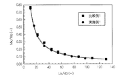
式(5)中のKM値は噴流の速度減衰係数であり、噴流のポテンシャルコアの長さを示す。ポテンシャルコアとは、噴流の初期流速および初期濃度(粉体濃度)が維持されている領域を指し、KM値が大きいほど噴流性能が高いことを意味する。
【0067】
KM値の解析結果を図4に示す。図4において、横軸はLx/d0を示し、縦軸は、Mx/Moを示す。
図4より、実施例1のKM値は、比較例1のKM値にほぼ等しく、実施例1のランス1では、ラバールノズルを備えた比較例1と同等の噴流性能が得られたことがわかる。
【0068】
表1に示した実施例において、断面積比(A2/A1)を2.19とし、ノズル広がり角(テーパ部3a、4aの傾斜角度θ1、θ2)0〜12°とした装置を用いてKM値を求めた。
表1に示した実施例において、ノズル広がり角を8°とし、断面積比(A2/A1)を0.5〜4とした装置を用いてKM値を求めた。
KM値をノズル形状因子で整理した結果を図5および図6に示す。
図5は、ノズル広がり角とKM値との関係を示すグラフである。
図5より、ノズル広がり角を4〜11°(好ましくは5〜10°)とすることによって、高いKM値が得られたことがわかる。
図6は、比較例1の断面積比(AL2/AL1)に対する、実施例1の断面積比(A2/A1)の比率と、KM値との関係を示すグラフである。
図6より、断面積比(AL2/AL1)に対する断面積比(A2/A1)の比率を、1〜3.0とすることによって、高いKM値が得られたことがわかる。
【0069】
(実施例2)
図2に示す構成のノズル22を有するランス21を作製した。装置仕様を表2に示す。
【0070】
(比較例2)
特開昭56-5914号公報で開示された形状のノズル(マルチジェットノズル)を有するランスを作製した。このノズルを図7に示す。
このノズルは、中心に形成された粉体流路33の外周側に、3つの一次支燃性流体流通孔34が形成され、その外周側に複数の燃料流体流通孔35が形成され、その外周側に複数の二次支燃性流体流通孔36が形成され、その外周側に水冷ジャケット37が設けられている。
装置仕様を表2に併せて示す。表中、スロート部とは、流通孔34内のスロート部34aを指す。スロート部断面積、スロート部径、出口断面積は1つの流通孔あたりの値を示す。装置仕様を表2に併せて示す。
【0071】
【表2】
上記実施例2および比較例2のランスを用いて粉体噴出試験を行った。
また、実施例2のランスを用い、燃料流体を用いずに粉体噴出試験を行った。結果を図8に示す。
【0073】
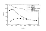
図8において、横軸はノズル先端から中心軸方向の距離を示し、縦軸は粉体速度を示す。なお、粉体速度の計測には、レーザードップラー法を用いた。
【0074】
図8に示すように、実施例2では、比較例2に比べ、粉体速度を大幅に高速化することができたことがわかる。
また、燃料流体を用いた場合には、粉体速度をさらに高めることができたことがわかる。
また燃料流体を用いた場合には、燃料流体を用いない場合に比べ、粉体速度が減衰しにくかったことがわかる。
【0075】
(実施例3)
350kgスケールの誘導溶解炉にて、温度1500℃、炭素濃度[C]が2.5重量%となるように溶鉄200kgを溶製した。
図1に示す構成の粉体吹込み装置1を、溶鉄の浴面から高さ350mmの位置に配置し、粉体および支燃性流体を溶鉄に向けて5分間にわたって噴出させた。
粉体としては、粒径500μm以下のコークス粉体を用いた。添加速度は15kg/hrとした。支燃性流体としては酸素を使用した。
また、攪拌のため、炉底のポーラスノズルよりArガスを炉内に供給した。供給速度は3Nm3/hrとした。装置仕様および試験結果を表3に示す。
【0076】
(実施例4)
燃料としてLPGを供給すること以外は実施例3と同様にして試験を行った。装置仕様および試験結果を表3に示す。
【0077】
(比較例3)
図7に示す装置を用いて試験を行った。装置仕様および試験結果を表3に示す。
【0078】
(比較例4)
単孔型(支燃性流体噴出孔が1つのもの)の装置を用いて試験を行った。装置仕様および試験結果を表3に示す。
【0079】
【表3】
(実施例5)
本発明を溶銑脱燐に適用した。燐濃度が0.08〜0.085重量%の5トンの溶銑を小型転炉に装入し、上方から粉体および純酸素ガスを供給し脱燐した。なお、装入前溶銑のその他の成分は[C]が4.3〜4.4重量%、[Si]が0.08〜0.10重量%であった。温度は1285〜1290℃であった。
粉体としては0.3〜1.5mm径(平均粒径1mm)の石灰を、溶銑トン当たり8kg用いた。
粉体吹込み装置としては、実施例1で用いたものと同様のものを用い、上記石灰粉を毎時5kgで8分間添加した。搬送流体としては純窒素ガス(毎分45Nm3)を用いた。
純酸素ガスは、石灰添加期間を通じ、毎時400Nm3で添加した。試験結果を表4に示す。
【0081】
(比較例5)
粉体吹込み装置を使用せず、袋詰めした5kgの石灰粉を30秒ごとに8回に分けて投入した。純酸素ガスの供給条件は実施例5と同様とした。試験結果を表4に示す。
【0082】
(比較例6)
比較例4で使用した単孔型の装置を用い、実施例5と同様の石灰を純酸素ガスとともに供給した。純酸素ガスの供給条件は実施例5と同様とした。
単孔型装置としては、ラバールノズルを有し、出口径が14.9mmのものを用いた。
処理後溶銑の成分は[C]が3.8〜3.9重量%、[Si]が0.01%以下であった。温度は、1310〜1320℃であった。試験結果を表4に示す。
なお、表中、P分配とは、スラグ中の燐の量に対するメタル中の燐の量の比率を示すものである。
【0083】
【表4】
表4より、実施例では、脱燐効率を高くし、溶銑中の燐濃度を低くすることができたことがわかる。
また、P分配の値より、投入した石灰の脱燐効率を高めることができたことがわかる。
【0085】
(実施例6〜10)
本発明を溶銑のスクラップ溶解に適用した。3トンの溶銑を小型転炉に装入し、上方から粉体および純酸素ガスを供給した。なお、装入前溶銑の成分は、[C]が4.7〜4.8重量%、[Si]が0.05重量%であった。温度は1230〜1240℃であった。
粉体としては0.3〜1.5mm径(平均粒径1mm)のプラスチック、石灰、またはコークスを用い、使用量は溶銑トンあたり40kgとした。
粉体吹込み装置としては、実施例4で用いたものを使用した。
試験開始から毎分0.5Nm3の純窒素ガスを搬送流体として、上記毎時4kgの粉体を添加した。純酸素ガスは、毎分400Nm3添加し、同時に燃料としてLPG(毎時10.9Nm3)を供給した。
30分間で溶解できたスクラップ量を測定した。試験結果を表5に示す。
【0086】
(比較例7〜10)
比較例7、8では、粉体吹込み装置を使用せず、石灰またはコークスを炉上部のシューターから投入し、ランスを用いて純酸素のみを供給した。
比較例9、10では、比較例4で用いた装置を用いた。
30分間で溶解できたスクラップ量を測定した。試験結果を表5に示す。
【0087】
【表5】
表5より、実施例では、スクラップの溶解量を増加できることがわかった。
これは、粉体を効率よく添加できたことに加え、酸素ガスを溶銑に対し効率的に添加できたため、粉体の燃焼による発生熱を有効に浴に着熱できたためであると考えられる。
【0089】
(実施例11、12)
本発明を溶銑の昇温に適用した。5トンの溶銑を小型の転炉に装入し、上方から粉体および純酸素ガスを供給した。なお、装入前の溶銑の[C]は4.0〜4.1重量%であり、温度は1260〜1270℃であった。
粉体としては0.3〜1.5mm径(平均粒径1mm)のプラスチック、石灰、またはコークスを用い、使用量は溶銑トンあたり8kgとした。
粉体吹込み装置としては、実施例4で用いたものを使用した。
試験開始から毎時0.5Nm3の純窒素ガスを搬送流体として、上記毎分5.3kgの粉体を添加した。純酸素ガスは、毎分400Nm3添加した。
8分間の処理を行った際の試験結果を表6に示す。
なお、表中には、溶銑の[C]の低下による昇温差を差し引き、燃料源添加による昇温分を計算で求め、補正昇温量として示した。
【0090】
(比較例11〜14)
比較例11、12では、粉体吹込み装置を使用せず、プラスチックを炉上部のシューターから投入し、ランスを用いて純酸素のみを供給した。
比較例13、14では、比較例4で用いた装置を用いた。
8分間の処理を行った際の試験結果を表6に示す。
【0091】
【表6】
表6より、実施例では、本発明では、昇温量を増加できることがわかった。
これは、粉体を効率よく添加できたことに加え、酸素ガスを溶銑に対し効率的に添加できたため、粉体の燃焼による発生熱を有効に浴に着熱できたためであると考えられる。
【0093】
上記実施例の結果より、本発明の粉体吹込み装置によれば、粉体流速を高め、粉体を浴の深部まで到達させ、燃焼や精錬反応を浴の深部において進行させることができ、精錬効率を向上させることができることがわかる。
【0094】
【発明の効果】
本発明の粉体吹込み装置では、粉体供給管と支燃性流体供給管の先端部に、これら供給管の隙間の支燃性流体流路が先端方向に向けて徐々に広くなるように形成されたテーパ部が設けられているので、支燃性流体を適度に膨張させ、高速の支燃性流体の流れを得ることができる。
よって、粉体供給管内の圧力を、先端付近において十分に低くすることができ、粉体供給管内の粉体の流速を高くすることができる。さらに、高速の支燃性流体流により粉体を搬送することができるため、粉体流速をさらに高めることができる。
従って、粉体を効率よく溶融金属等に吹き込むことが可能となる。
【0095】
また、支燃性流体供給管の外周側に、燃料流体を供給する燃料流体供給管が設けられ、この燃料流体供給管は、粉体供給管からの粉体流を囲むように、燃料流体を噴出させることができる構成を採用することによって、粉体流を囲む流体の流れを高速化し、この流体の流れによって搬送される粉体の流速をさらに高めることができる。さらには、粉体が径方向に拡散するのを防ぐことができる。
従って、粉体をいっそう効率よく溶融金属等に吹き込むことが可能となる。
【0096】
支燃性流体供給管の先端部に、ほぼ一定の内径を有する直胴部が形成された構成を採用することによって、噴出する燃料流体が径方向に拡散するのを防ぎ、燃料流体の火炎を安定化することができる。
また直胴部の内面に、周方向に沿う溝が形成されている構成によって、燃料流体の火炎をさらに安定化し、流体の流れの乱れを防ぐことができる。
従って、粉体の流れをいっそう高速化することができる。
【図面の簡単な説明】
【図1】 本発明の粉体吹込み装置の第1の実施形態を示す断面図である。
【図2】 本発明の粉体吹込み装置の第2の実施形態を示す断面図である。
【図3】 試験結果を示すグラフである。
【図4】 試験結果を示すグラフである。
【図5】 試験結果を示すグラフである。
【図6】 試験結果を示すグラフである。
【図7】 比較例2の粉体吹込み装置に用いられるノズルの断面図である。
【図8】 試験結果を示すグラフである。
【符号の説明】
1、21・・・ランス(粉体吹込み装置)、2・・・ノズル、3・・・粉体供給管、4・・・支燃性流体供給管、5・・・燃料流体供給管、7・・・スロート部、8・・・燃料流体噴出部、12・・・支燃性流体流路[0001]
BACKGROUND OF THE INVENTION
The present invention relates to an apparatus and a refining method in which powders such as coke and waste fuel are blown into a liquid such as molten metal together with a fluid such as oxygen and oxygen-enriched air.
[0002]
[Prior art]
An apparatus (hereinafter referred to as a lance) that blows powder into a liquid together with a fluid such as gas or liquid is used in various production processes.
In particular, in the electric furnace steelmaking process, powdered solid fuel (powder) such as coke is blown into the molten metal together with oxygen, burned, and the combustion energy is applied to the molten metal, thereby reducing the power intensity. Reduced.
Also in the refining process, powdered flux is blown into the molten metal to promote metallurgical reaction and improve reaction efficiency.
In order to perform these processes efficiently, it is necessary to deeply infiltrate the powder into the molten metal. For this purpose, it is necessary to blow the powder at a high speed.
Conventionally, non-water-cooled and water-cooled lances have been used as devices for blowing powder into molten metal.
These apparatuses can immerse the lance in a high-temperature molten metal or molten slag and directly blow powder into the molten metal.
However, in the case of a non-water-cooled lance, the lance itself melts and needs to be replaced frequently. In the case of a water-cooled lance, frequent maintenance is required to prevent nozzle clogging. For this reason, there was a problem in workability in any lance.
[0003]
On the other hand,
In these apparatuses, since it is not necessary to immerse the lance in molten metal or molten slag, the cost and workability required for maintenance of the nozzle can be greatly improved.
However, in the case of the apparatus described in
Further, in the case of the apparatus disclosed in
[0004]
In addition, lances such as those described in Non-Patent
The apparatus disclosed in these documents can mix powder in advance with oxygen, or mix oxygen and powder supplied in a separate system immediately before the throat section, and jet the mixed stream from a Laval nozzle. It has become.
In this apparatus, since a high-speed oxygen jet and powder are mixed and ejected from the Laval nozzle, the jet and powder can be sped up.
In this apparatus, powder is mixed with a high-speed oxygen jet in front of the throat portion, so that the throat portion is particularly worn. For this reason, the nozzle may be easily deformed, and it may be difficult to eject a supersonic jet. In addition, when a high-concentration oxygen-enriched fluid such as pure oxygen is used as a carrier fluid, the combustible powder cannot be conveyed.
In addition,
According to this apparatus, nozzle abrasion due to powder supply can be prevented.
[0005]
[Patent Document 1]
US Pat. No. 5,788,921
[0006]
[Patent Document 2]
JP 56-5914 A
[0007]
[Patent Document 3]
US Pat. No. 5,788,921
[0008]
[Patent Document 4]
JP 56-5914 A
[0009]
[Non-Patent Document 1]
Tsuyoshi Doi (ed.), Converter steelmaking, Nikkan Kogyo Shimbun, p. 192
[0010]
[Patent Document 5]
JP-A-8-81712
[0011]
[Patent Document 6]
JP 7-216430 A
[0012]
[Problems to be solved by the invention]
However, this nozzle is effective in preventing powder scattering because the high-speed oxygen jet is formed in an annular shape surrounding the powder flow path, but the mixing position of the powder and oxygen is separated from the nozzle. As described above, it is difficult to increase the speed of the powder flow.
An apparatus that can supply powder to the vicinity of the high-speed oxygen jet outlet has also been proposed. However, a nozzle for bending the central powder flow in the direction of the oxygen jet tube is required, and the powder is used in this nozzle. There was a problem that the nozzle deteriorated.
[0013]
Further, in the steel refining process, oxidative refining is performed in which oxygen is supplied to molten iron produced in a blast furnace or the like (for example, molten iron or molten steel obtained by decarburizing molten iron). At this time, various auxiliary materials may be added.
For example, a heat compensation material such as a carbon material is used for raising the temperature of molten metal or melting iron scrap. A refining material such as CaO is used for removing impurities. Alloys are used to add components required for the material properties of the final product. When performing the reduction treatment, iron ore, manganese ore and the like are used.
As a method of adding the auxiliary material to the molten iron, there are a method of adding from above and a method of adding in the bath. However, in the case of adding upward, there are problems such as solubility and charging efficiency. In some cases, it was difficult to add them in terms of equipment.
In recent years, powdered auxiliary materials have been added from above using an oxygen lance. In this method, fine particles having a diameter of several mm or less can be added, so that the solubility and reactivity of the auxiliary raw material can be improved. Moreover, since it is not necessary to immerse the apparatus in the bath, the problem of equipment is also eliminated.
However, when the powder is blown, there is a problem that the blowing speed is insufficient, the powder is scattered, and the powder is not sufficiently mixed in the bath.
This invention is made | formed in view of the said situation, and it aims at providing the apparatus which can raise the flow rate of powder and can blow this powder into a liquid efficiently.
[0014]
[Means for Solving the Problems]
The powder blowing device of the present invention is a device for blowing powder into a liquid, and a combustion-supporting fluid supply pipe for supplying a combustion-supporting fluid is provided on the outer peripheral side of the powder supply pipe for supplying powder. A nozzle having a multi-tube structure is provided, and a gap between these supply pipes serves as a combustion-supporting fluid flow path, and at the tip of the powder supply pipe and the combustion-supporting fluid supply pipe, a combustion support fluid flow path is provided. A taper portion formed so as to gradually widen in the distal direction is provided, and a throat portion having a relatively narrow gap is formed on the base end side from the taper portion. The inclination angle of the tapered portion with respect to the supply pipe central axis is preferably 4 to 11 °, and more preferably 5 to 10 °.
The ratio (A2 / A1) between the cross-sectional area A1 of the combustion-supporting fluid flow path at the throat portion and the cross-sectional area A2 of the combustion-supporting fluid flow path at the tip of the supply pipe is within the range represented by the following equation. It is preferable.
[Expression 2]
In the powder blowing device of the present invention, a fuel fluid ejection portion for guiding a fuel fluid from a fuel fluid flow path to the inside of the fuel support fluid supply tube is formed in the fuel support fluid supply tube, and the fuel fluid with respect to the central axis of the supply tube It can be set as the structure whose inclination | tilt angle (theta) 3 of a jet part is 5-90 degrees.
The powder blowing device of the present invention can be configured such that a groove along the circumferential direction is formed on the inner surface of the combustion-supporting fluid supply pipe on the tip side from the fuel fluid ejection portion.
In the powder blowing device of the present invention, a straight body portion having a substantially constant inner diameter may be formed on the tip side from the fuel fluid ejection portion of the combustion-supporting fluid supply pipe.
[0015]
The operation method of the melting / smelting furnace of the cold iron source of the present invention is to spray the combustion-supporting fluid containing oxygen and the powder together with the fuel fluid toward the cold iron source using a powder blowing device. The method of operating the furnace for melting and refining the cold iron source, and independently supplying the fuel fluid supply amount in the melting step in which the cold iron source is melted and in the refining step after the cold iron source is melted down Is set.
In the operation method of the cold iron source melting / smelting furnace of the present invention, the above powder blowing apparatus can be used.
The operation method of the melting / smelting furnace of the cold iron source according to the present invention includes at least one of desiliconization, dephosphorization, desulfurization, decarburization, temperature increase, heat addition, scrap melting, alloy melting, reduction treatment, and degassing. Can be targeted.
In refining, one or more of solid carbon source, hydrocarbon source, lime source, magnesium source, aluminum source, iron ore, manganese ore, and alloy can be added to the molten iron.
As the combustion-supporting fluid, one or more of pure oxygen gas, industrial oxygen gas, and air can be used.
[0016]
The refining method of the present invention supplies powder using a powder blowing apparatus, and supplies a combustion-supporting fluid so as to entrain the powder from the periphery of the powder flow. It is characterized by refining the molten iron by ejecting a sexual fluid toward the molten iron.
The initial velocity of the combustion-supporting fluid when jetting the combustion-supporting fluid is equal to or higher than the speed of sound, and preferably the Mach number M ≧ 1.10.
In the refining method of the present invention, it is preferable that the fuel fluid is ejected around the combustion-supporting fluid, and the fuel fluid is ejected while burning.
In the refining method of the present invention, the above powder blowing device can be used.
The refining method of the present invention can target at least one of desiliconization, dephosphorization, desulfurization, decarburization, temperature increase, heat addition, scrap melting, alloy melting, reduction treatment, and degassing.
In refining, one or more of solid carbon source, hydrocarbon source, lime source, magnesium source, aluminum source, iron ore, manganese ore, and alloy can be added to the molten iron.
As the combustion-supporting fluid, one or more of pure oxygen gas, industrial oxygen gas, and air can be used.
In the refining method of the present invention, sensible heat or latent heat can be recovered from the exhaust gas generated during refining.
[0017]
DETAILED DESCRIPTION OF THE INVENTION
FIG. 1 is a schematic configuration diagram showing a main part of a first embodiment of a powder blowing apparatus of the present invention.
A powder blowing device (hereinafter referred to as a lance) 1 shown in FIG. 1 includes a
The
The
[0018]
The
A powder supply
The inclination angle θ1 of the powder supply
In addition, although the straight tubular
[0019]
The combustion-supporting
A combustion-supporting fluid supply
The combustion-supporting fluid supply
Due to the
It is preferable that the inclination angle θ2 of the combustion-supporting fluid supply
[0020]
The inclination angles θ1 and θ2 of the
For this reason, the atmospheric pressure in the
When the inclination angles θ1 and θ2 are less than the above range, the combustion-supporting fluid is insufficiently expanded, so that the speed of the combustion-supporting fluid is decreased and the powder flow rate is insufficient. When the tilt angles θ1 and θ2 exceed the above range, the jetting combustion-supporting fluid expands excessively, so that the speed of the combustion-supporting fluid becomes low at the nozzle outlet and the powder flow rate becomes insufficient.
The inclination angle θ2 of the
That is, the difference between the inclination angle θ1 and the inclination angle θ2 is preferably 1 ° or less. When this difference exceeds this range, the flow of the combustion-supporting fluid is disturbed, and the flow rate of the powder becomes insufficient.
[0021]
A
For this reason, the combustion-supporting fluid flow path 12 (hereinafter referred to as the throat section 7) in the
Assuming that the cross-sectional area A1 of the
[0022]
[Equation 3]
When the cross-sectional area ratio A2 / A1 is less than the above range, the combustion-supporting fluid is not sufficiently expanded, so that the speed of the combustion-supporting fluid is lowered and the powder flow rate is insufficient. Further, if the cross-sectional area ratio A2 / A1 exceeds the above range, the jetting combustion-supporting fluid expands excessively, so that the speed of the combustion-supporting fluid becomes low at the nozzle outlet and the powder flow rate becomes insufficient.
The pressure outside the nozzle means the pressure of the atmosphere in which the
[0024]
The inner diameter of the throat portion 7 (the inner diameter of the
In general, the cross-sectional area AL1 of the throat portion of the Laval nozzle is designed with a value obtained from Equation (2).
[0025]
[Expression 4]
The inner diameter d1 of the
The inner diameter (outlet diameter) d2 of the
[0027]
[Equation 5]
When (A2 / A1) is less than 1 time of (AL2 / AL1), the combustion-supporting fluid is insufficiently expanded, the speed of the combustion-supporting fluid is decreased, and the ejection speed of the powder is decreased. . If (A2 / A1) is more than 3.0 times (AL2 / AL1), the jet of combustion-supporting fluid will expand excessively, so the speed of the support-supporting fluid will be low at the nozzle outlet, and powder The jetting speed of the is reduced.
On the other hand, when (A2 / A1) is 1 to 3.0 times (AL2 / AL1), the combustion-supporting fluid is slightly overexpanded and flows at high speed (becomes a supersonic state). ). In addition, since the atmospheric pressure in the combustion-supporting
[0029]
A fuel
The fuel
In order to eject the fuel fluid around the powder flow, the fuel
Further, the fuel
[0030]
The fuel
In particular, when the fuel fluid is a gas, the inclination angle θ3 is preferably 5 ° or more and 60 ° or less.
When the inclination angle θ3 is less than the above range, mixing of the fuel fluid and the combustion-supporting fluid becomes insufficient, and the flame tends to become unstable.
When the inclination angle θ3 exceeds the above range, the fuel fluid ejected from the fuel
[0031]
The fuel
Between the front end of the fuel
[0032]
The water-cooling
[0033]
Next, a method of using the
A mixture containing powder such as coke and waste fuel and a carrier fluid is supplied into the
Nitrogen, air, oxygen, oxygen-enriched air, etc. can be used as the carrier fluid.
At the same time, the combustion-supporting fluid is supplied to the combustion-supporting fluid flow path 12 (the gap between the
[0034]
As described above, since the
For this reason, the combustion-supporting
Therefore, the pressure in the
[0035]
At the same time, a fuel fluid such as LNG (liquefied natural gas) is supplied to the fuel fluid flow path 13 (gap between the
As a result, the mixed fluid of the combustion-supporting fluid and the fuel fluid is ejected together with the powder while burning.
[0036]
Thereby, the fluid flowing around the powder flow can be sped up, and the flow velocity of the powder conveyed by this fluid flow can be further increased. Furthermore, it is possible to prevent the powder from diffusing in the radial direction.
Accordingly, the powder can be efficiently blown into the molten metal or the like.
Further, since the powder can be supplied without passing through the
Furthermore, since the powder and the combustion-supporting fluid can be supplied from different systems, that is, from the
[0037]
As fuel fluid, in addition to LNG, LPG (liquefied petroleum gas), CO,H 2 , CO /H 2 A mixed gas can be used. Liquid fuels such as heavy oil and kerosene can also be used.
[0038]
Next, a second embodiment of the lance of the present invention will be described with reference to FIG.
FIG. 2 shows a
The
A
The
[0039]
Next, a method of using the
At the same time, the fuel fluid is supplied to the fuel
[0040]
In the
Further, since the
For this reason, even when the flow rate of the combustion-supporting fluid in the combustion-supporting
Therefore, the flow rate of the powder can be further increased.
[0041]
The fluid in the present invention includes a fluid in a gas state, a liquid state, and a state in which a mist-like liquid is contained in the gas.
[0042]
Next, the operation method of the melting / smelting furnace of the cold iron source of the present invention will be described.
In order to dissolve the solid raw material (cold iron source), an electric furnace is used to charge the solid raw material into the furnace and dissolve it by arc heating.
Since a cold spot may occur in the furnace due to insufficient supply heat, in the operation method of the present invention, the burner lance can be installed so that the cold spot can be heated.
In the electric furnace melting, there are mainly a step of melting a solid raw material (melting step) and a step of heating and refining a liquid material (molten steel or the like) that has melted down into a liquid state.
[0043]
In the operation method of the present invention, the cold iron source is dissolved by spraying the mixed fluid of the combustion-supporting fluid containing oxygen and the fuel fluid to the cold iron source while burning using the powder blowing device. And refine.
When a solid raw material (cold iron source) is dissolved using a powder blowing device, conditions suitable for the respective steps are employed in the step of melting the solid raw material and the refining step after the solid raw material has melted down. Thus, the fuel fluid supply amount is set independently.
The powder blowing device of the present invention has an excellent fusing ability because the mixed fluid of the combustion-supporting fluid and the fuel fluid can be ejected at a high speed together with the flame.
In the melting step, since the solid raw material can be heated while being melted, the heating efficiency can be increased. For this reason, it is possible to increase the heat receiving efficiency of the fuel, burn more fuel, and reduce the power intensity.
[0044]
On the other hand, in the refining process after melting down, the inside of the furnace has molten steel, slag, etc. at the bottom, and the upper part is a space, so even if a large amount of fuel is supplied, the heat receiving efficiency is lowered.
For this reason, by supplying the minimum amount of fuel within a range that can prevent the fluid flow velocity from being attenuated, the combustion supporting fluid (oxygen) is efficiently blown from the furnace wall toward the bath, and the decarburization reaction is performed. And promote slag forming.
[0045]
In the dissolving step, it is preferable to satisfy 1 ≦ oxygen ratio <3.This facilitates fusing and melting of the solid material, and combustible components such as carbon monoxide generated in the furnace can be burned.
The oxygen ratio is the ratio of the amount of oxygen supplied to the amount of oxygen required for complete combustion of the fuel fluid.
In the refining process after smelting, the fuel fluid supply rate is significantly reduced, preferably the oxygen ratio is 3 or more, and the combustion-supporting fluid (oxygen) is blown at a high speed to perform decarburization reaction and slag forming. The solid raw material can be dissolved while promoting.
[0046]
Thus, according to the method of setting the fuel fluid supply amount independently in the melting step in which the solid raw material dissolves and in the refining step after the solid raw material has melted down, a simple method of adjusting only the fuel flow rate Therefore, the efficiency of each process can be improved.
Furthermore, in a refining process after smelting, a powder composed of a carbon source such as coke and waste such as waste plastic can be blown into the solid raw material at a high speed. Moreover, this powder can be burned in a raw material, and a raw material can be heated efficiently.
[0047]
Next, the refining method of the present invention will be described.
The refining method of the present invention supplies powder using a powder blowing apparatus, and supplies a combustion-supporting fluid so as to entrain the powder from the periphery of the powder flow. This is a method of refining the molten iron by ejecting a sexual fluid toward the molten iron.
The powder can be supplied by being conveyed by a carrier gas.
[0048]
In general, the hot metal discharged from the blast furnace is received by a transporting device such as a hot metal ladle, and after pretreatment such as desiliconization, dephosphorization, and desulfurization, it is charged into the converter, and if necessary. And then decarburized. The decarburized molten steel is transported by a transport container such as a molten steel pan and is subjected to a secondary refining process.
The refining method of the present invention can be carried out in a refining furnace such as a converter, a smelting reduction furnace, a decarburizing furnace, or a secondary refining furnace that receives molten iron (hot metal or molten steel). The refining method of the present invention can also be carried out in a transport container such as a blast furnace pan, a chaotic car (topped car), and a charging pot.
It is preferable that the said container has a processing apparatus which processes the waste gas of a combustion-supporting fluid.
[0049]
Hereinafter, the example which applied the refining method of this invention with respect to the molten iron in a converter is demonstrated.
In general, the hot metal charged in the converter is decarburized by supplying oxygen (feeding acid) from the lance, and is supplied to the next process as molten steel. At this time, a refining agent (CaO, dolomite, etc.), ores (iron ore, manganese ore, etc.), alloys and the like are added for the purpose of adjusting the components of slag and molten steel.
In addition, a sufficient amount of heat is required when melting iron scrap, raising the temperature, and the like. In addition, when reduction treatment is performed using ores such as manganese ore, sufficient heat of reduction is required. For this reason, when the amount of carbon or the like in the molten iron is not sufficient, heat compensation is required even if the supply of oxygen is sufficient, and carbonaceous materials such as coke, soil graphite, and coal are added.
[0050]
As auxiliary materials, solid carbon sources such as coke and coal: hydrocarbon sources such as plastics: CaO,CaCO 3 Source of lime containing: MgO,MgCO 3 Magnesium source including: Al,Al 2 O 3 One or more of aluminum sources including: iron ore: manganese ore: alloys can be mentioned.
A solid carbon source, a hydrocarbon source, and an aluminum source act as a fuel source.
The auxiliary material is usually added by being naturally dropped from above. The auxiliary material is preferably a powder having a small particle size in order to improve solubility and reactivity, but when oxygen is supplied, the powder is likely to be scattered by the exhaust gas.
For this reason, those having a particle size of several tens of mm or more are used, but the solubility and reactivity are impaired.
[0051]
In the present invention, the powder blowing device is used to supply the powder and to supply the combustion-supporting fluid so as to entrain the powder from the periphery of the powder flow. It ejects toward the molten iron.
As the powder blowing device, the one shown in FIG. 1 can be used.
In addition, the powder blowing and the combustion-supporting fluid supply may be performed by a single device, or a powder-blowing device and a combustion-supporting fluid supply device may be used.
In the present invention, the fuel fluid can be ejected around the combustion-supporting fluid, and the fuel fluid can be ejected while burning.
[0052]
In the present invention, since the combustion-supporting fluid is supplied so as to entrain the powder from around the powder flow, the speed of the powder can be increased by the combustion-supporting fluid.
For this reason, the powder can be blown into the bath or near the bath surface.
Therefore, the solubility and reactivity of the powder can be improved.
[0053]
The initial velocity of the combustion-supporting fluid when jetting the combustion-supporting fluid is equal to or higher than the speed of sound, and preferably the Mach number M ≧ 1.10. When the initial speed is less than this range, the speed of the powder becomes insufficient.
If the powder and supporting fluid increase in speed, the depth of penetration into the bath will increase, but if the supporting fluid reaches the furnace bottom, the furnace may deteriorate. The fluid velocities are preferably adjusted to the extent that they do not reach the furnace bottom.
[0054]
The refining method of the present invention can be applied to one or more of desiliconization, dephosphorization, desulfurization, decarburization, temperature increase, heat addition, scrap melting, alloy melting, reduction treatment, and degassing.
Heat addition is performed for heat compensation when adding an iron source or an alloy source. The reduction treatment is performed using iron ore, manganese ore and the like.
What is necessary is just to select and use the refining agent used in the case of refining according to the objective of refining. For example, in desiliconization or dephosphorization, silicic acid or phosphoric acid produced by reaction with oxygen needs to be stabilized as slag, and therefore, a lime source having a stabilizing effect is preferably used as a refining agent.
The source of lime is CaOCaCO 3 It is preferable to use one having at least one of them as a main component because it can be rapidly melted and slagged.
[0055]
In the refining method of the present invention, the powder can be added at a high speed, and therefore, even when the particle size of the powder is small (for example, a particle size of several hundreds μm or less), scattering and the like are prevented and the powder is efficiently produced. Insufflation is possible.
The addition amount of the auxiliary raw material can be set according to conditions such as a refining processing amount, a required refining degree, and an allowable refining time.
[0056]
In addition, when reducing ore, iron ore, manganese ore, and other ores may be added with a solvent (such as lime), coke, or coal as a reducing agent or a fuel source for heat addition. is there.
In this invention, since these can be added at high speed, a reduction rate and reduction efficiency can be improved.
In addition, it is possible to efficiently burn the fuel source and to effectively generate the generated heat in order to compensate for the temperature drop during ore reduction or scrap melting, or simply to raise the temperature of the bath.
[0057]
When a solid carbon source, a hydrocarbon source, an aluminum source, or the like is used as a fuel source, these can be added at high speed as powder, so that they can be supplied to the deep part of the bath and combustion efficiency can be improved. .
The combustion efficiency can be adjusted by adjusting the particle size of the powder, the ratio of the powder to the combustion-supporting fluid, and the like.
The ratio between the powder and the combustion-supporting fluid can be adjusted by increasing or decreasing the oxygen ratio (air ratio). At this time, the ratio between the powder and the combustion-supporting fluid can be determined in consideration of the amount of oxide (carbon, silicon, etc.) in the molten iron and the intended combustion state.
[0058]
As the combustion-supporting fluid, one or more of pure oxygen gas, industrial oxygen gas, and air can be used.
The combustion-supporting fluid is not limited to a gas state, but may be a liquid state or a gas-liquid mixture in which a mist-like liquid is contained in the gas.
An inert gas such as argon, nitrogen gas, or carbon monoxide gas can be used as the carrier fluid for conveying the powder. In addition, as long as there is no problem such as combustion in the piping, a combustion-supporting fluid can be used.
As for fuel, in addition to hydrocarbon gases such as LPG and LNG, blast furnace gas and converter gas recovered in the steelworks can be used.
In the present invention, sensible heat or latent heat can be recovered from exhaust gas generated during refining using a heat exchanger or the like.
[0059]
In the refining method of the present invention, since the combustion-supporting fluid can be sped up, the combustion-supporting fluid can be blown to the deeper part of the bath than before, and the refining efficiency can be improved.
[0060]
【Example】
(Example 1)
A
Table 1 shows the device specifications. In the table, the nozzle spread angle means the inclination angles θ1 and θ2 of the
[0061]
(Comparative Example 1)
A lance having a Laval nozzle was produced.
The apparatus specifications are also shown in Table 1.
[0062]
[Table 1]
Using a Pitot tube, the jet characteristics in Example 1 and Comparative Example 1 were examined without supplying powder.
The following formula (5) was used for the evaluation of the jet velocity.
[0064]
[Formula 6]
The results are shown in FIG. In FIG. 3, the horizontal axis indicates the distance from the nozzle tip in the direction of the supply pipe central axis, and the vertical axis indicates the jet velocity.
From FIG. 3, the lance of Example 1 is provided with the
[0066]
The KM value in equation (5) is the velocity attenuation coefficient of the jet, and indicates the length of the potential core of the jet. The potential core refers to a region where the initial flow velocity and the initial concentration (powder concentration) of the jet are maintained, and means that the larger the KM value, the higher the jet performance.
[0067]
The analysis result of KM value is shown in FIG. In FIG. 4, the horizontal axis represents Lx / d0, and the vertical axis represents Mx / Mo.
FIG. 4 shows that the KM value of Example 1 is substantially equal to the KM value of Comparative Example 1, and that the
[0068]
In the embodiment shown in Table 1, KM is used with an apparatus in which the cross-sectional area ratio (A2 / A1) is 2.19 and the nozzle spread angle (inclination angles θ1, θ2 of the
In the examples shown in Table 1, the KM value was determined using an apparatus in which the nozzle divergence angle was 8 ° and the cross-sectional area ratio (A2 / A1) was 0.5-4.
The results of arranging the KM values by the nozzle shape factor are shown in FIGS.
FIG. 5 is a graph showing the relationship between the nozzle spread angle and the KM value.
FIG. 5 shows that a high KM value was obtained by setting the nozzle spread angle to 4 to 11 ° (preferably 5 to 10 °).
FIG. 6 is a graph showing the relationship between the ratio of the cross-sectional area ratio (A2 / A1) of Example 1 to the cross-sectional area ratio (AL2 / AL1) of Comparative Example 1 and the KM value.
FIG. 6 shows that a high KM value was obtained by setting the ratio of the cross-sectional area ratio (A2 / A1) to the cross-sectional area ratio (AL2 / AL1) to 1 to 3.0.
[0069]
(Example 2)
A
[0070]
(Comparative Example 2)
A lance having a nozzle (multi-jet nozzle) having a shape disclosed in Japanese Patent Application Laid-Open No. 56-5914 was produced. This nozzle is shown in FIG.
In this nozzle, three primary combustion-supporting fluid circulation holes 34 are formed on the outer peripheral side of the
The device specifications are also shown in Table 2. In the table, the throat portion refers to the
[0071]
[Table 2]
Using the lances of Example 2 and Comparative Example 2, a powder ejection test was performed.
Further, a powder ejection test was performed using the lance of Example 2 without using the fuel fluid. The results are shown in FIG.
[0073]
In FIG. 8, the horizontal axis indicates the distance from the nozzle tip in the central axis direction, and the vertical axis indicates the powder velocity. A laser Doppler method was used for measuring the powder velocity.
[0074]
As shown in FIG. 8, it can be seen that in Example 2, the powder speed was significantly increased as compared with Comparative Example 2.
It can also be seen that when the fuel fluid was used, the powder velocity could be further increased.
It can also be seen that when the fuel fluid was used, the powder velocity was more difficult to attenuate than when the fuel fluid was not used.
[0075]
(Example 3)
In a 350 kg scale induction melting furnace, 200 kg of molten iron was melted so that the temperature was 1500 ° C. and the carbon concentration [C] was 2.5% by weight.
The
As the powder, a coke powder having a particle size of 500 μm or less was used. The addition rate was 15 kg / hr. Oxygen was used as the combustion-supporting fluid.
For stirring, Ar gas was supplied into the furnace from a porous nozzle at the bottom of the furnace. Supply speed is 3Nm3/ Hr. Table 3 shows the apparatus specifications and test results.
[0076]
Example 4
The test was performed in the same manner as in Example 3 except that LPG was supplied as the fuel. Table 3 shows the apparatus specifications and test results.
[0077]
(Comparative Example 3)
The test was performed using the apparatus shown in FIG. Table 3 shows the apparatus specifications and test results.
[0078]
(Comparative Example 4)
The test was conducted using a single-hole type device (having one combustion-supporting fluid ejection hole). Table 3 shows the apparatus specifications and test results.
[0079]
[Table 3]
(Example 5)
The present invention was applied to hot metal dephosphorization. 5 tons of hot metal having a phosphorus concentration of 0.08 to 0.085 wt% was charged into a small converter, and dephosphorized by supplying powder and pure oxygen gas from above. In addition, the other components of the hot metal before charging were 4.3 to 4.4% by weight of [C] and 0.08 to 0.10% by weight of [Si]. The temperature was from 1285 to 1290 ° C.
As the powder, 8 kg of lime having a diameter of 0.3 to 1.5 mm (average particle diameter of 1 mm) was used per ton of hot metal.
As the powder blowing device, the same one as used in Example 1 was used, and the lime powder was added at 5 kg / hour for 8 minutes. The carrier fluid is pure nitrogen gas (45 Nm / min)3) Was used.
Pure oxygen gas is 400 Nm per hour throughout the lime addition period3Added at. The test results are shown in Table 4.
[0081]
(Comparative Example 5)
Without using a powder blowing device, 5 kg of lime powder packed in a bag was charged in 8 portions every 30 seconds. The conditions for supplying pure oxygen gas were the same as those in Example 5. The test results are shown in Table 4.
[0082]
(Comparative Example 6)
Using the single hole type apparatus used in Comparative Example 4, the same lime as in Example 5 was supplied together with pure oxygen gas. The conditions for supplying pure oxygen gas were the same as those in Example 5.
As the single-hole type device, a device having a Laval nozzle and having an exit diameter of 14.9 mm was used.
The components of the hot metal after the treatment were [C] of 3.8 to 3.9% by weight and [Si] of 0.01% or less. The temperature was 1310-1320 ° C. The test results are shown in Table 4.
In the table, the P distribution indicates the ratio of the amount of phosphorus in the metal to the amount of phosphorus in the slag.
[0083]
[Table 4]
From Table 4, it can be seen that in the examples, the dephosphorization efficiency was increased and the phosphorus concentration in the hot metal could be decreased.
Moreover, it turns out that the dephosphorization efficiency of the input lime was able to be raised from the value of P distribution.
[0085]
(Examples 6 to 10)
The present invention was applied to hot metal scrap melting. Three tons of hot metal was charged into a small converter, and powder and pure oxygen gas were supplied from above. In addition, as for the component of the hot metal before charging, [C] was 4.7 to 4.8% by weight, and [Si] was 0.05% by weight. The temperature was 1230 to 1240 ° C.
As the powder, plastic, lime, or coke having a diameter of 0.3 to 1.5 mm (average particle diameter of 1 mm) was used, and the amount used was 40 kg per ton of hot metal.
As the powder blowing device, the one used in Example 4 was used.
0.5 Nm / min from the start of the test3The pure nitrogen gas was used as a carrier fluid and 4 kg of the above powder was added per hour. Pure oxygen gas is 400 Nm / min3At the same time as LPG (10.9 Nm / h as fuel)3).
The amount of scrap that could be melted in 30 minutes was measured. The test results are shown in Table 5.
[0086]
(Comparative Examples 7-10)
Comparative Examples 7 and 8Then, without using a powder blowing device, lime or coke was introduced from a shooter at the top of the furnace, and pure oxygen was supplied using a lance.
Comparative Examples 9 and 10Then, the apparatus used in Comparative Example 4 was used.
The amount of scrap that could be melted in 30 minutes was measured. The test results are shown in Table 5.
[0087]
[Table 5]
From Table 5, it was found that the amount of scrap dissolved can be increased in the examples.
This is considered to be because the heat generated by the combustion of the powder could be effectively applied to the bath because the oxygen could be efficiently added to the hot metal in addition to the efficient addition of the powder.
[0089]
(Examples 11 and 12)
The present invention was applied to hot metal temperature elevation. Five tons of hot metal was charged into a small converter, and powder and pure oxygen gas were supplied from above. In addition, [C] of the hot metal before charging was 4.0 to 4.1 wt%, and the temperature was 1260 to 1270 ° C.
As the powder, plastic, lime, or coke having a diameter of 0.3 to 1.5 mm (average particle diameter of 1 mm) was used, and the amount used was 8 kg per ton of hot metal.
As the powder blowing device, the one used in Example 4 was used.
0.5 Nm / hour from the start of the test3The above pure nitrogen gas was used as a carrier fluid and 5.3 kg of the powder was added per minute. Pure oxygen gas is 400 Nm / min3Added.
Table 6 shows the test results when the treatment was performed for 8 minutes.
In the table, the difference in temperature rise due to the decrease in hot metal [C] was subtracted, and the temperature rise due to the addition of the fuel source was calculated and indicated as the corrected temperature rise.
[0090]
(Comparative Examples 11-14)
Comparative Examples 11 and 12Then, without using the powder blowing device, plastic was introduced from the shooter at the top of the furnace and only pure oxygen was supplied using a lance.
Comparative Examples 13 and 14Then, the apparatus used in Comparative Example 4 was used.
Table 6 shows the test results when the treatment was performed for 8 minutes.
[0091]
[Table 6]
From Table 6, it was found that, in the examples, the temperature increase amount can be increased in the present invention.
This is considered to be because the heat generated by the combustion of the powder could be effectively applied to the bath because the oxygen could be efficiently added to the hot metal in addition to the efficient addition of the powder.
[0093]
From the results of the above examples, according to the powder blowing device of the present invention, the powder flow rate can be increased, the powder can reach the deep part of the bath, and the combustion and refining reaction can proceed in the deep part of the bath. It can be seen that the refining efficiency can be improved.
[0094]
【The invention's effect】
In the powder blowing apparatus of the present invention, the combustion-supporting fluid flow path in the gap between these supply pipes is gradually widened in the tip direction at the tip of the powder supply pipe and the combustion-supporting fluid supply pipe. Since the formed tapered portion is provided, the combustion-supporting fluid can be appropriately expanded to obtain a high-speed flow of the combustion-supporting fluid.
Therefore, the pressure in the powder supply tube can be sufficiently reduced in the vicinity of the tip, and the flow rate of the powder in the powder supply tube can be increased. Furthermore, since the powder can be conveyed by a high-speed combustion-supporting fluid flow, the powder flow rate can be further increased.
Accordingly, the powder can be efficiently blown into the molten metal or the like.
[0095]
Further, a fuel fluid supply pipe for supplying a fuel fluid is provided on the outer peripheral side of the combustion-supporting fluid supply pipe. The fuel fluid supply pipe encloses the fuel fluid so as to surround the powder flow from the powder supply pipe. By adopting a configuration that can be ejected, the flow of the fluid surrounding the powder flow can be accelerated, and the flow velocity of the powder conveyed by this fluid flow can be further increased. Furthermore, it is possible to prevent the powder from diffusing in the radial direction.
Therefore, the powder can be blown into the molten metal or the like more efficiently.
[0096]
By adopting a configuration in which a straight body portion having a substantially constant inner diameter is formed at the tip of the combustion-supporting fluid supply pipe, the fuel fluid that is ejected is prevented from diffusing in the radial direction, and the flame of the fuel fluid is suppressed. Can be stabilized.
Further, the configuration in which the groove along the circumferential direction is formed on the inner surface of the straight body portion can further stabilize the flame of the fuel fluid and prevent the fluid flow from being disturbed.
Therefore, the flow rate of the powder can be further increased.
[Brief description of the drawings]
FIG. 1 is a cross-sectional view showing a first embodiment of a powder blowing apparatus of the present invention.
FIG. 2 is a sectional view showing a second embodiment of the powder blowing apparatus of the present invention.
FIG. 3 is a graph showing test results.
FIG. 4 is a graph showing test results.
FIG. 5 is a graph showing test results.
FIG. 6 is a graph showing test results.
7 is a cross-sectional view of a nozzle used in the powder blowing device of Comparative Example 2. FIG.
FIG. 8 is a graph showing test results.
[Explanation of symbols]
1, 2 ... Lance (powder blowing device), 2 ... Nozzle, 3 ... Powder supply pipe, 4 ... Combustion fluid supply pipe, 5 ... Fuel fluid supply pipe, 7 ... Throat part, 8 ... Fuel fluid ejection part, 12 ... Combustion fluid flow path
Claims (8)
粉体を供給する粉体供給管の外周側に、支燃性流体を供給する支燃性流体供給管が設けられた多重管構造のノズルを有し、これら供給管の隙間が支燃性流体流路とされ、
粉体供給管と支燃性流体供給管の先端部には、支燃性流体流路が先端方向に向けて徐々に広くなるように形成されたテーパ部が設けられ、これらテーパ部より基端側に、前記隙間が比較的狭いスロート部が形成され、
供給管中心軸に対するテーパ部の傾斜角度が、4〜11°であり、
スロート部における支燃性流体流路の断面積A1と、供給管の先端における支燃性流体流路の断面積A2との比率(A2/A1)が、次式で表される範囲内であることを特徴とする粉体吹込み装置。
On the outer peripheral side of the powder supply pipe for supplying powder, there is a multi-tube structure nozzle provided with a combustion support fluid supply pipe for supplying a combustion support fluid, and the gap between these supply pipes is the combustion support fluid A flow path,
The tip of the powder supply pipe and the combustion-supporting fluid supply pipe is provided with a taper part formed so that the combustion-supporting fluid flow path gradually widens in the tip direction. On the side, a throat portion with a relatively narrow gap is formed,
The inclination angle of the tapered portion to the feed pipe central axis, Ri 4 to 11 ° der,
The ratio (A2 / A1) between the cross-sectional area A1 of the combustion-supporting fluid flow path at the throat portion and the cross-sectional area A2 of the combustion-supporting fluid flow path at the tip of the supply pipe is within the range represented by the following equation. A powder blowing device characterized by that.
支燃性流体供給管の外周側に、燃料流体を供給する燃料流体供給管が設けられ、これら供給管の隙間が燃料流体流路とされ、
燃料流体供給管は、粉体供給管からの粉体流あるいは支燃性流体供給管からの支燃性流体流の周囲に、燃料流体を噴出させることができるように構成されていることを特徴とする粉体吹込み装置。 In the powder blowing apparatus according to claim 1,
A fuel fluid supply pipe for supplying fuel fluid is provided on the outer peripheral side of the combustion-supporting fluid supply pipe, and a gap between these supply pipes serves as a fuel fluid flow path.
The fuel fluid supply pipe is configured such that the fuel fluid can be ejected around the powder flow from the powder supply pipe or the combustion support fluid flow from the support fluid supply pipe. A powder blowing device.
Priority Applications (1)
| Application Number | Priority Date | Filing Date | Title |
|---|---|---|---|
| JP2002288116A JP4019117B2 (en) | 2001-09-28 | 2002-09-30 | Powder blowing apparatus and refining method |
Applications Claiming Priority (3)
| Application Number | Priority Date | Filing Date | Title |
|---|---|---|---|
| JP2001302734 | 2001-09-28 | ||
| JP2001-302734 | 2001-09-28 | ||
| JP2002288116A JP4019117B2 (en) | 2001-09-28 | 2002-09-30 | Powder blowing apparatus and refining method |
Publications (3)
| Publication Number | Publication Date |
|---|---|
| JP2003172584A JP2003172584A (en) | 2003-06-20 |
| JP2003172584A5 JP2003172584A5 (en) | 2004-07-08 |
| JP4019117B2 true JP4019117B2 (en) | 2007-12-12 |
Family
ID=26623377
Family Applications (1)
| Application Number | Title | Priority Date | Filing Date |
|---|---|---|---|
| JP2002288116A Expired - Lifetime JP4019117B2 (en) | 2001-09-28 | 2002-09-30 | Powder blowing apparatus and refining method |
Country Status (1)
| Country | Link |
|---|---|
| JP (1) | JP4019117B2 (en) |
Families Citing this family (25)
| Publication number | Priority date | Publication date | Assignee | Title |
|---|---|---|---|---|
| JP4845078B2 (en) * | 2003-12-16 | 2011-12-28 | Jfeスチール株式会社 | Hot metal desulfurization method |
| JP5031977B2 (en) * | 2004-05-31 | 2012-09-26 | Jfeスチール株式会社 | Hot metal dephosphorization method |
| JP2006291334A (en) * | 2005-04-14 | 2006-10-26 | Sumitomo Metal Ind Ltd | Method for recycling dust at pretreatment of molten iron |
| JP4735169B2 (en) * | 2005-09-30 | 2011-07-27 | Jfeスチール株式会社 | Hot metal dephosphorization method |
| JP5087955B2 (en) * | 2006-03-23 | 2012-12-05 | Jfeスチール株式会社 | Melting reduction method |
| JP5286768B2 (en) * | 2007-06-06 | 2013-09-11 | Jfeスチール株式会社 | Burner lance for charging granular material in smelting reduction furnace and method for producing molten metal by smelting reduction |
| KR101144057B1 (en) * | 2008-12-19 | 2012-05-22 | 주식회사 태성산전 | Lime injector |
| JP5481894B2 (en) * | 2009-03-18 | 2014-04-23 | Jfeスチール株式会社 | Melting reduction method |
| JP5609081B2 (en) * | 2009-12-01 | 2014-10-22 | Jfeスチール株式会社 | Hot metal desulfurization method |
| JP5707702B2 (en) * | 2010-01-29 | 2015-04-30 | Jfeスチール株式会社 | Hot metal dephosphorization method |
| CA2829030C (en) * | 2011-01-15 | 2018-01-30 | Almamet Gmbh | Agent for treating molten metals, method for the production and use thereof |
| JP5962156B2 (en) * | 2011-04-12 | 2016-08-03 | Jfeスチール株式会社 | Method for refining molten iron |
| JP2013209737A (en) * | 2011-04-27 | 2013-10-10 | Jfe Steel Corp | Method for producing molten steel |
| JP2013209738A (en) * | 2011-04-27 | 2013-10-10 | Jfe Steel Corp | Method of manufacturing molten steel |
| JP5870771B2 (en) * | 2011-05-23 | 2016-03-01 | Jfeスチール株式会社 | Manufacturing method of molten steel |
| JP2013047371A (en) * | 2011-07-27 | 2013-03-07 | Jfe Steel Corp | Method for refining molten iron |
| JP5870868B2 (en) * | 2011-07-29 | 2016-03-01 | Jfeスチール株式会社 | Method of refining hot metal in converter |
| JP5928095B2 (en) * | 2012-03-30 | 2016-06-01 | Jfeスチール株式会社 | Method for refining molten iron |
| JP5928094B2 (en) * | 2012-03-30 | 2016-06-01 | Jfeスチール株式会社 | Method for refining molten iron |
| JP5365678B2 (en) * | 2011-10-17 | 2013-12-11 | Jfeスチール株式会社 | Powder blowing lance with burner function, molten iron refining method and molten metal smelting reduction method using the powder blowing lance |
| US9580764B2 (en) | 2011-10-17 | 2017-02-28 | Jfe Steel Corporation | Top-blowing lance and method for refining molten iron using the same |
| JP6051561B2 (en) * | 2012-03-30 | 2016-12-27 | Jfeスチール株式会社 | Manufacturing method of molten steel |
| JP5949627B2 (en) * | 2013-03-28 | 2016-07-13 | Jfeスチール株式会社 | Method of refining hot metal in converter |
| EP4056722A4 (en) * | 2019-11-06 | 2023-01-11 | JFE Steel Corporation | Method for producing molten iron using electric furnace |
| CN114410883B (en) * | 2021-12-30 | 2023-03-03 | 钢铁研究总院 | Oxygen lance for cooperatively injecting oxygen, powder and inert gas and injection method |
-
2002
- 2002-09-30 JP JP2002288116A patent/JP4019117B2/en not_active Expired - Lifetime
Also Published As
| Publication number | Publication date |
|---|---|
| JP2003172584A (en) | 2003-06-20 |
Similar Documents
| Publication | Publication Date | Title |
|---|---|---|
| JP4019117B2 (en) | Powder blowing apparatus and refining method | |
| JP4735169B2 (en) | Hot metal dephosphorization method | |
| EP2752497B1 (en) | Powder injection lance and method of refining molten iron using said powder injection lance | |
| JP6036172B2 (en) | Method of refining hot metal in converter | |
| JP5707702B2 (en) | Hot metal dephosphorization method | |
| JP5382275B1 (en) | Vacuum refining method for molten steel | |
| RU2697113C1 (en) | Refining method of molten steel in equipment for vacuum degassing | |
| KR101018535B1 (en) | Refining ferroalloys | |
| JP3577066B2 (en) | Burner lance and refining method | |
| JP4050195B2 (en) | Method of melting and refining furnace for refrigerating iron source and refining method | |
| JP4715384B2 (en) | Method for dephosphorizing hot metal and top blowing lance for dephosphorization | |
| JP5834980B2 (en) | Manufacturing method of molten steel | |
| JP5928094B2 (en) | Method for refining molten iron | |
| JP2003194307A5 (en) | ||
| JP5962156B2 (en) | Method for refining molten iron | |
| JP5915568B2 (en) | Method of refining hot metal in converter type refining furnace | |
| JP5585633B2 (en) | Method of refining hot metal in converter | |
| JP2012082492A (en) | Converter refining method | |
| JP5870868B2 (en) | Method of refining hot metal in converter | |
| JP2020094247A (en) | Lance for refining, lance apparatus for refining, electric furnace, and steelmaking process | |
| JP5928095B2 (en) | Method for refining molten iron | |
| WO2022163121A1 (en) | Top blowing lance for converter, method for adding auxiliary raw material, and method for refining of molten iron | |
| JP2019090078A (en) | Immersion lance for blowing and refining method of molten iron | |
| JP6939733B2 (en) | Refining method of molten steel under reduced pressure | |
| JP6939828B2 (en) | Acid feeding refining method for molten iron |
Legal Events
| Date | Code | Title | Description |
|---|---|---|---|
| A977 | Report on retrieval |
Free format text: JAPANESE INTERMEDIATE CODE: A971007 Effective date: 20051201 |
|
| A131 | Notification of reasons for refusal |
Free format text: JAPANESE INTERMEDIATE CODE: A131 Effective date: 20061212 |
|
| A521 | Request for written amendment filed |
Free format text: JAPANESE INTERMEDIATE CODE: A523 Effective date: 20070213 |
|
| A521 | Request for written amendment filed |
Free format text: JAPANESE INTERMEDIATE CODE: A821 Effective date: 20070213 |
|
| A02 | Decision of refusal |
Free format text: JAPANESE INTERMEDIATE CODE: A02 Effective date: 20070403 |
|
| A521 | Request for written amendment filed |
Free format text: JAPANESE INTERMEDIATE CODE: A523 Effective date: 20070507 |
|
| A911 | Transfer to examiner for re-examination before appeal (zenchi) |
Free format text: JAPANESE INTERMEDIATE CODE: A911 Effective date: 20070607 |
|
| TRDD | Decision of grant or rejection written | ||
| A01 | Written decision to grant a patent or to grant a registration (utility model) |
Free format text: JAPANESE INTERMEDIATE CODE: A01 Effective date: 20070717 |
|
| A711 | Notification of change in applicant |
Free format text: JAPANESE INTERMEDIATE CODE: A711 Effective date: 20070815 |
|
| A61 | First payment of annual fees (during grant procedure) |
Free format text: JAPANESE INTERMEDIATE CODE: A61 Effective date: 20070815 |
|
| A521 | Request for written amendment filed |
Free format text: JAPANESE INTERMEDIATE CODE: A821 Effective date: 20070815 |
|
| FPAY | Renewal fee payment (event date is renewal date of database) |
Free format text: PAYMENT UNTIL: 20101005 Year of fee payment: 3 |
|
| R150 | Certificate of patent or registration of utility model |
Ref document number: 4019117 Country of ref document: JP Free format text: JAPANESE INTERMEDIATE CODE: R150 Free format text: JAPANESE INTERMEDIATE CODE: R150 |
|
| FPAY | Renewal fee payment (event date is renewal date of database) |
Free format text: PAYMENT UNTIL: 20101005 Year of fee payment: 3 |
|
| FPAY | Renewal fee payment (event date is renewal date of database) |
Free format text: PAYMENT UNTIL: 20101005 Year of fee payment: 3 |
|
| FPAY | Renewal fee payment (event date is renewal date of database) |
Free format text: PAYMENT UNTIL: 20111005 Year of fee payment: 4 |
|
| R250 | Receipt of annual fees |
Free format text: JAPANESE INTERMEDIATE CODE: R250 |
|
| FPAY | Renewal fee payment (event date is renewal date of database) |
Free format text: PAYMENT UNTIL: 20111005 Year of fee payment: 4 |
|
| FPAY | Renewal fee payment (event date is renewal date of database) |
Free format text: PAYMENT UNTIL: 20121005 Year of fee payment: 5 |
|
| R250 | Receipt of annual fees |
Free format text: JAPANESE INTERMEDIATE CODE: R250 |
|
| FPAY | Renewal fee payment (event date is renewal date of database) |
Free format text: PAYMENT UNTIL: 20121005 Year of fee payment: 5 |
|
| FPAY | Renewal fee payment (event date is renewal date of database) |
Free format text: PAYMENT UNTIL: 20121005 Year of fee payment: 5 |
|
| FPAY | Renewal fee payment (event date is renewal date of database) |
Free format text: PAYMENT UNTIL: 20131005 Year of fee payment: 6 |
|
| R250 | Receipt of annual fees |
Free format text: JAPANESE INTERMEDIATE CODE: R250 |
|
| R250 | Receipt of annual fees |
Free format text: JAPANESE INTERMEDIATE CODE: R250 |
|
| R250 | Receipt of annual fees |
Free format text: JAPANESE INTERMEDIATE CODE: R250 |
|
| R250 | Receipt of annual fees |
Free format text: JAPANESE INTERMEDIATE CODE: R250 |
|
| R250 | Receipt of annual fees |
Free format text: JAPANESE INTERMEDIATE CODE: R250 |
|
| R250 | Receipt of annual fees |
Free format text: JAPANESE INTERMEDIATE CODE: R250 |
|
| R250 | Receipt of annual fees |
Free format text: JAPANESE INTERMEDIATE CODE: R250 |
|
| R250 | Receipt of annual fees |
Free format text: JAPANESE INTERMEDIATE CODE: R250 |
|
| R250 | Receipt of annual fees |
Free format text: JAPANESE INTERMEDIATE CODE: R250 |
|
| S111 | Request for change of ownership or part of ownership |
Free format text: JAPANESE INTERMEDIATE CODE: R313111 |
|
| R350 | Written notification of registration of transfer |
Free format text: JAPANESE INTERMEDIATE CODE: R350 |
|
| R250 | Receipt of annual fees |
Free format text: JAPANESE INTERMEDIATE CODE: R250 |
|
| EXPY | Cancellation because of completion of term |