JP4014322B2 - Method and apparatus for transmitting accumulated data and engineering conditions on tires to remote locations - Google Patents
Method and apparatus for transmitting accumulated data and engineering conditions on tires to remote locations Download PDFInfo
- Publication number
- JP4014322B2 JP4014322B2 JP36301398A JP36301398A JP4014322B2 JP 4014322 B2 JP4014322 B2 JP 4014322B2 JP 36301398 A JP36301398 A JP 36301398A JP 36301398 A JP36301398 A JP 36301398A JP 4014322 B2 JP4014322 B2 JP 4014322B2
- Authority
- JP
- Japan
- Prior art keywords
- tire
- data
- transponder
- rim
- antenna
- Prior art date
- Legal status (The legal status is an assumption and is not a legal conclusion. Google has not performed a legal analysis and makes no representation as to the accuracy of the status listed.)
- Expired - Fee Related
Links
Images


Classifications
-
- B—PERFORMING OPERATIONS; TRANSPORTING
- B60—VEHICLES IN GENERAL
- B60C—VEHICLE TYRES; TYRE INFLATION; TYRE CHANGING; CONNECTING VALVES TO INFLATABLE ELASTIC BODIES IN GENERAL; DEVICES OR ARRANGEMENTS RELATED TO TYRES
- B60C23/00—Devices for measuring, signalling, controlling, or distributing tyre pressure or temperature, specially adapted for mounting on vehicles; Arrangement of tyre inflating devices on vehicles, e.g. of pumps or of tanks; Tyre cooling arrangements
-
- H—ELECTRICITY
- H01—ELECTRIC ELEMENTS
- H01Q—ANTENNAS, i.e. RADIO AERIALS
- H01Q1/00—Details of, or arrangements associated with, antennas
- H01Q1/12—Supports; Mounting means
- H01Q1/22—Supports; Mounting means by structural association with other equipment or articles
- H01Q1/2208—Supports; Mounting means by structural association with other equipment or articles associated with components used in interrogation type services, i.e. in systems for information exchange between an interrogator/reader and a tag/transponder, e.g. in Radio Frequency Identification [RFID] systems
- H01Q1/2241—Supports; Mounting means by structural association with other equipment or articles associated with components used in interrogation type services, i.e. in systems for information exchange between an interrogator/reader and a tag/transponder, e.g. in Radio Frequency Identification [RFID] systems used in or for vehicle tyres
-
- B—PERFORMING OPERATIONS; TRANSPORTING
- B60—VEHICLES IN GENERAL
- B60C—VEHICLE TYRES; TYRE INFLATION; TYRE CHANGING; CONNECTING VALVES TO INFLATABLE ELASTIC BODIES IN GENERAL; DEVICES OR ARRANGEMENTS RELATED TO TYRES
- B60C23/00—Devices for measuring, signalling, controlling, or distributing tyre pressure or temperature, specially adapted for mounting on vehicles; Arrangement of tyre inflating devices on vehicles, e.g. of pumps or of tanks; Tyre cooling arrangements
- B60C23/02—Signalling devices actuated by tyre pressure
- B60C23/04—Signalling devices actuated by tyre pressure mounted on the wheel or tyre
- B60C23/0408—Signalling devices actuated by tyre pressure mounted on the wheel or tyre transmitting the signals by non-mechanical means from the wheel or tyre to a vehicle body mounted receiver
- B60C23/0483—Wireless routers between wheel mounted transmitters and chassis mounted receivers
-
- B—PERFORMING OPERATIONS; TRANSPORTING
- B60—VEHICLES IN GENERAL
- B60C—VEHICLE TYRES; TYRE INFLATION; TYRE CHANGING; CONNECTING VALVES TO INFLATABLE ELASTIC BODIES IN GENERAL; DEVICES OR ARRANGEMENTS RELATED TO TYRES
- B60C23/00—Devices for measuring, signalling, controlling, or distributing tyre pressure or temperature, specially adapted for mounting on vehicles; Arrangement of tyre inflating devices on vehicles, e.g. of pumps or of tanks; Tyre cooling arrangements
- B60C23/02—Signalling devices actuated by tyre pressure
- B60C23/04—Signalling devices actuated by tyre pressure mounted on the wheel or tyre
- B60C23/0491—Constructional details of means for attaching the control device
- B60C23/0494—Valve stem attachments positioned inside the tyre chamber
-
- G—PHYSICS
- G06—COMPUTING; CALCULATING OR COUNTING
- G06K—GRAPHICAL DATA READING; PRESENTATION OF DATA; RECORD CARRIERS; HANDLING RECORD CARRIERS
- G06K19/00—Record carriers for use with machines and with at least a part designed to carry digital markings
- G06K19/06—Record carriers for use with machines and with at least a part designed to carry digital markings characterised by the kind of the digital marking, e.g. shape, nature, code
- G06K19/067—Record carriers with conductive marks, printed circuits or semiconductor circuit elements, e.g. credit or identity cards also with resonating or responding marks without active components
- G06K19/07—Record carriers with conductive marks, printed circuits or semiconductor circuit elements, e.g. credit or identity cards also with resonating or responding marks without active components with integrated circuit chips
- G06K19/077—Constructional details, e.g. mounting of circuits in the carrier
- G06K19/07749—Constructional details, e.g. mounting of circuits in the carrier the record carrier being capable of non-contact communication, e.g. constructional details of the antenna of a non-contact smart card
- G06K19/07758—Constructional details, e.g. mounting of circuits in the carrier the record carrier being capable of non-contact communication, e.g. constructional details of the antenna of a non-contact smart card arrangements for adhering the record carrier to further objects or living beings, functioning as an identification tag
- G06K19/07764—Constructional details, e.g. mounting of circuits in the carrier the record carrier being capable of non-contact communication, e.g. constructional details of the antenna of a non-contact smart card arrangements for adhering the record carrier to further objects or living beings, functioning as an identification tag the adhering arrangement making the record carrier attachable to a tire
Description
【0001】
【技術分野】
本発明は空気タイヤについてのさまざまな物理条件をモニターする方法と、タイヤに関する蓄積情報を収納した記憶装置およびタイヤ内の工学条件を検出するモニター装置を有するタイヤに関する。特に、本発明はタイヤの内張りに取付られ、タイヤに関する蓄積データを維持し、好ましくはタイヤのリムに搭載したトランスポンダーとの間でデータの送受信をするためのアンテナと低出力バッテリーを含む記憶装置とモニター装置を有する、タイヤの構成と方法に関する。トランスポンダーは受信したデータをタイヤの外部に設けたアンテナを介して離れた場所に送信する。
【0002】
【従来技術及びその課題】
摩耗、内部温度、内部圧力に関するタイヤの状態をモニターすることが望ましい。特に大型トラックのタイヤについては、高価であること、車両効率を最大にするためには定期的に維持管理をしなければならないことから、タイヤをモニターすることの利点は大きい。過去、こうしたモニター作業には、タイヤ本体内に埋設され、電磁結合(inductive magnetic coupling)によって集積回路を励起(energize)する無線周波数送信(radio frequency transmission)によって起動(activated)されるパッシブ集積回路が一般に使われてきた。電磁結合または容量結合に依存するパッシブ装置は一般に長大なコイル巻線が必要なため、タイヤの構造や組立て工程に大幅な修正が必要になるという欠点がある。こうしたパッシブ装置のもう一つの重大な欠点は、普通タイヤから数インチ以内という極めて近接位置に呼びかけ応答機を配置してタイヤと装置間の通信をしなければならない点である。この近接性という要件のため、呼びかけ応答機を車両の車輪の一つ一つに装着しなければならず、連続モニターを実用レベルで実施できない。駐車中の車両の各タイヤに埋設したパッシブ装置からデータを手作業で収集するのも、近接性の要件があるため煩雑かつ時間のかかる作業になる。
【0003】
タイヤの状態をモニターするために使われるその他の従来装置では、バルブステム(valve stem)など、タイヤの外部に配置した自家動力型(self-powered)回路が使われてきた。外部に装着した装置は天候やいたずらなどによる損傷を受けやすいという欠点がある。さらに、外部に装着した装置はモニターを行っている特定のタイヤから簡単にはずれてしまいやすい。
【0004】
従来のタイヤモニター認識装置のもう一つの欠点として、通信の送受信が従来の無線周波数を使って行われるため、比較的大型のアンテナが必要になり、そのためタイヤの外側に取付けたり、あるいはタイヤの構造や組立工程に比較的大掛かりな修正が必要になるような方法で取付けなけらばならなくなる。
【0005】
こうした問題の多くは、米国特許5,500,065;5,562,787;5,573,610;5,573,611に記載される方法とタイヤ構成によって取り除かれてきた。しかし、これらの装置はタイヤの車輪チェンバー(tire wheel chamber)内に収納されており、タイヤを介して外部の受信機にデータを送信するのがむずかしい。また、いくつかの追加装置が弁ステムの中に収納されていてタイヤに直接取り付いていず、そのため装置が収納されている同一リム上の異なるタイヤが取り外されて別のものと交換される可能性があるため、タイヤについての恒久的な記録が得られない。また、従来装置はタイヤ、車輪、あるいは弁ステムのいずれかのみに取付られているため、多くの用途分野で望まれる設計上の柔軟性がない。わけても重要なのは、RF周波数通信の場合、信号はタイヤ側壁を通さなければならないが、トラックのタイヤの側壁は厚みがあって送信効率が大幅に落ちるため、離れた場所に信号を送信するのが困難な点である。
【0006】
上記4件の特許に記載されるタイヤのモニター方法と装置は、先行技術に比べ多くの利点はあるが、モジュール機能をS/N比、再現性、距離について外部RF通信受信の改善が可能な別個の構成部品、すなわち一つはタイヤの内張りに直接取付て温度と圧力を検出する装置、もう一つはタイヤのリムに装着してタイヤ/車輪からのデータをタイヤの外部に設けたアンテナによって外部の受信機に送信するトランスポンダーに分割し、これら2個の装置を使ってより用途が広く柔軟性に富むタイヤのモニターシステムを提供することが望ましい。
【0007】
【課題を解決するための手段】
本発明の一側面によると、好ましくはタイヤタグ(tire tag)に組込んだ起動可能な記憶装置とモニター装置または検出装置が、車両のタイヤのうち少なくともひとつの内部でその内面に装着され、前記タグにはタイヤに関する蓄積データが収納され、タイヤ内部の工学条件を検出するセンサーが設けられ、タイヤタグはタイヤ内に形成される加圧可能なキャビティ内でタイヤのリム上に装着したトランスポンダーによって起動されることからなる、タイヤのモニター方法が提供される。
【0008】
本発明の他の目的は、記憶装置、検出装置は比較的低出力のバッテリーと、蓄積データと検出状態を直接タイヤのキャビティ内のリムに搭載したトランスポンダーに送信するためのアンテナを有し、トランスポンダーは記憶装置からの蓄積データを外部アンテナを介して離れた場所に送信するために、タイヤタグ内のバッテリーより出力の大きい電源またはバッテリーをもつことができるようにした方法とタイヤ構成を提供することにある。
【0009】
他の目的は、検出装置がタイヤの内部圧力や温度など、タイヤの工学条件を検出するためのセンサーを含み、この情報もトランスポンダーと外部アンテナによって離れた場所にに送信されるような方法とタイヤ構成を提供することにある。
【0010】
さらなる目的は、上記のような方法とタイヤ構成であって、トランスポンダーのアンテナがタイヤのリムまたはタイヤの空気制御弁(air control valve)を直接通って延在することでタイヤの外部にその終端がくるようになっており、その結果、アンテナがタイヤの加圧可能なキャビティ内に完全に位置するために周囲のスチール製ベルト、タイヤ側壁、タイヤのリムによる干渉を受ける場合に比べ、蓄積および検出データを外部源(external source)に送信するための出力が少なくてすむようにする方法とタイヤ構成を提供することにある。
【0011】
本発明のさらなる目的は、検出装置のアンテナがリムを通って加圧可能なキャビティーの外に延在する場合、離れた場所に位置する特定の呼びかけ応答機にアンテナを合わせる(tune)ために、アンテナをさまざまな長さに調整できる方法とタイヤ構成を提供することにある。
【0012】
さらなる目的は、記憶装置と検出装置を収納するタイヤタグを、タイヤ製造過程でタイヤ壁部に取付けるか、あるいは製造後、応力、歪み、循環疲労、衝撃、変化が最小ですむような方法と位置を選んで、化学的にまたは熱によって作用させる(heat activatable)ことができる接着剤を用いてタイヤに取付けることができるような方法とタイヤ構成を提供することにある。
【0013】
本発明のさらに他の目的は、装置の一つがタイヤの内張りに直接取付けられていて温度と圧力を検出するためのものであり、2番目の装置が単純なトランスポンダーであって、このトランスポンダーはタイヤリムに取付けられており、タイヤタグから収集したデータを直接リム内の密封穴を通って、または空気制御弁ステムを通って受信機に送信する方法とタイヤ構成と2つの別個の装置を用いる装備を提供することにある。
【0014】
これらの目的および利点は本発明の改良方法によって達成されるが、その概要は空気タイヤに関する蓄積データと工学条件を離れた場所に送信するものであり、タイヤは内部の圧力キャビティーを形成するリムの上に装着されており、前記方法は、タイヤに関するデータの蓄積を可能にする装置と、タイヤの工学条件を検出する装置をタイヤに設け、前記内部圧力キャビティ内で装置をタイヤに固定し、装置に記憶させたタイヤデータと前記装置が検出した工学条件を検出するために、増幅器、第1のアンテナ、第1の電源、および制御回路を含むトランスポンダーを設け、リムに隣接するが装置からは離れた位置で圧力キャビティ内にトランスポンダーを固定し、第1のアンテナの一部を圧力キャビティの外にくるように配置し、装置からの蓄積データと検出した工学条件をトランスポンダーに送信し、圧力キャビティの外に位置する第1のアンテナによってトランスポンダーから離れた場所に向けて蓄積データと検出工学条件を送信するステップとからなる。
【0015】
これら目的および利点はさらに、リム上に装着される、加圧可能なキャビティをタイヤとリムの間に規定し、タイヤに関するデータを蓄積しタイヤ内部の工学条件を検出するための第1の手段と、前記データと検出工学条件を離れた場所に送信するための手段を有するタイヤにより達成されるもので、前記第1の手段は加圧可能なキャビティ内でタイヤ上に装着され、タイヤに関する蓄積データを収納するデータ蓄積装置と、加圧可能なキャビティ内でタイヤ上に装着されたセンサー装置を含み、第2の手段はリムに隣接するが加圧可能なキャビティ内の第1の手段からは離れた位置に装着され、データ記憶装置とセンサー装置からのデータを収集し、収集データをタイヤに接していない離れた場所に再発信するためのトランスポンダーを含み、前記トランスポンダーはさらに電源と、リムを通ってタイヤのキャビティの外部にある場所に延在して蓄積データと検出工学条件を離れた場所に送信するための第1のアンテナを含んでいる。
【0016】
【実施例】
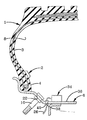
出願人が原理の応用を検討した最善の態様を例示する好ましい実施例を以下に記述し、図面に示すが、これらは特許請求項で特に明確に指摘されかつ規定されている。図1はタイヤの内張りに装着したタイヤタグ内に収納された記憶装置と検出装置、およびタイヤの加圧可能なキャビティ内の空気制御弁に装着したトランスポンダーを有する空気タイヤの半分を示す部分断面略図である。
【0017】
図2はリムに装着したトランスポンダーとリム内部の密封穴を通るアンテナを示す、図2に類似の部分断面略図である。
【0018】
図3は記憶装置と検出装置を収納するタイヤタグの構成部品を示すブロック図である。
【0019】
図4はトランスポンダーの構成部品を示すブロック図である。
【0020】
全図面について同様の部分は同様の数字で表す。
【0021】
図1を参照すると、ビードパッケージ(bead package)4に隣接する区域で内壁または内張り3に固定したタイヤタグ2をもつ空気タイヤ1の部分断面が図示されている。タイヤ1は全体を参照番号6で示す通常の金属製リムに装着され、タイヤ内の空気圧を調節するための空気制御弁10を介して供給される空気を受け入れるキャビティ8の内部圧力チェンバーを形成している。タイヤタグ2の位置は、その内容を参照することで本書の一部となす米国特許5,500,065;5,562,787;5,573,610;5,573,611で論じられるように、タイヤの趾底(toe bottom)から距離にして約1、2インチがタイヤの循環歪みを減らすうえでも好ましい。
【0022】
図3に概略を示すように、タイヤタグ2は記憶装置12、モニターまたは検出装置14を含み、好ましくはアンテナ16とバッテリー18を含む。記憶装置12は好ましくはタグ2を装着した特定のタイヤに関する識別情報などの蓄積データを収納する。検出装置14は好ましくはタイヤの内部温度および/または圧力などのタイヤの工学条件を検出するセンサーを含む。
【0023】
タグ2はタイヤ製造時にタイヤと一緒に組立ててもよく、あるいは前記4件の特許に記載されるような溶剤あるいは熱によって作用する接着剤(solvent or heat activatable adhesive)を使ってタイヤに固定してもよい。
【0024】
本発明の主な特長の一つによれば、トランスポンダー20はリム6に形成した通常の開口22を通って延在する空気制御弁10の上に装着するか、またはその中に組込む。トランスポンダー20は好ましくは被包材料で包み込んで、周囲温度、圧力およびその他暴露を受ける可能性のある厳しい環境条件の影響がおよぶのを少なくする。図4に示すように、トランスポンダー20はバッテリー24、アンテナ26、および前記情報によってアンテナ26を駆動するために、増幅器26に接続されかつこれを作動させるための適切な電子制御回路とを含むマイクロチップを含んでいることが好ましく、前記情報はついでアンテナ26によって離れた場所にある呼びかけ応答ユニットに送信される。必要であれば、1種以上の周波数を使って同時に送受信を行うために一つ以上のアンテナをトランスポンダー20に設けてもよい。この呼びかけ応答ユニットはトラック運転台に設けてもよく、あるいは移動型あるいは固定式にして全く外部の位置に遠く離して設置してもよく、車両が呼びかけ応答ユニットの近辺にあるときユニットが作動可能になる。マイクロチップ28、増幅器30、タイヤタグ2の細部は、先に参照した4件の特許に詳述されるタイプのものであることが好ましく、したがってその詳細に言及しない。
【0025】
図2はトランスポンダーの変形例34であって、弁10に代えてリム6の内部表面36に直接装着されている。アンテナ26はリム6に形成した穴38の中に位置する密封グロメット40を通ってタイヤの外まで延在することにより、収集データの送信における望ましい効率向上、S/N比の向上、信号再現性の強化が得られ、タイヤ内部からタイヤの側壁を通って信号を送信しなければならない場合従来なら生じた信号強度の損失がほとんど無いため、車両のタイヤと、離れた場所にある呼びかけ応答機との間の送信距離を大きくとることが可能になる。
【0026】
本発明のもう一つの主な特長によれば、この改良装置とタイヤ構成ではトランスポンダーの無線通信能力を活用して、タイヤ内部のデータを、タイヤのIDや温度、圧力といった使用歴(service history)を保持する固定式蓄積装置に送受信したり、これらデータやその他同様のデータを無線周波数(RF)通信を介して外部源(external source)に送受信したりする。このことはタイヤ、車輪あるいは弁のステムに全面的に取付けられていて、その構成部品がすべてその中に組込まれている従来のタイヤタグとは対照的である。したがって、本発明の改良装置はタイヤタグのモジュール設計に柔軟性をもたらし、モジュール機能を別個の構成部品に分割することが可能になり、タイヤを通って外部の受信機あるいは呼びかけ応答機に信号を送信する必要がないため、S/N比、再現性、距離に関して外部RF通信の受信が改善される。同様に、本発明の概念を損なうことなくトランスポンダーを直接リムまたは空気制御弁に装着することができるが、いずれの場合もアンテナはリムを通ってタイヤ外部の位置に延在する。
【0027】
改良装備は少なくとも2つの電子部品からなり、その一つは多くの点で上述の特許に規定される内張りに取付けられたタイヤタグに類似している。これはパッチ(patch)を用いることができ、温度や圧力を検出する電子装置を含み、メモリー内のデータのID記憶(ID storage of data in memory)をもたらす。この装置は第2の装置、すなわちタイヤ−車輪で囲まれる部分(within the tire-wheel envelope)またはキャビティ内部に位置するトランスポンダーとの間でデータの送受信を行う。トランスポンダーは比較的単純で安価な装置でありそのため、通信が強化される上に通信コストが低下する。同様に、変換器をリムまたは空気制御弁に直接装着することで、タイヤの製造初期工程や加硫工程、それに続く踏み面つけ直し工程(retreading)など、大型トラックのタイヤでは一般に行われる工程でタイヤに生じる高温の影響が変換器におよぶのを避けることができる。また、特定のマイクロチップやセンサーを特定のタイヤ専用として設ける必要がなく、装着するタイヤを特に考慮せずに交換してさまざまな結果を達成することができる。
【0028】
また、バッテリー24はタイヤタグ2のバッテリー18よりもかなり大型で出力の高いものでもよい。これによりタグ2が簡単になりコストやサイズが従来のモニターシステムのタグ装置に比べて小さくなる。また、バッテリー24は従来装置のようにタイヤの内張りの片側に位置するのではなく、タイヤのリムに搭載されているため、バッテリー24をより大型でパワフルにすることもできる。またバッテリーは加硫熱の影響を受けることがなく、タイヤの一部として組込まれる可能性のあるタイヤタグの組込み構成部品として形成された場合に比べ、より簡単に交換が可能である。
【0029】
本発明の重要な利点は、アンテナ26をグロメット40またはその他タイヤに設けた密封開口の中を通す、あるい図1に示すように空気注入口のステム(inflation stem)の中または上に一体的に組込むかすることで、キャビティ8の外部にアンテナ26を配置させたことにある。これにより、バッテリーが完全にタイヤのキャビティー内部に位置する従来システムのように、通常のスチールベルトとタイヤの側壁で周囲を囲まれることがなく、そのため離れた場所にある呼びかけ応答機に情報を送信するためにバッテリー26が消費する電力が少なくなる。さらに、タイヤの外部で簡単にアクセスできるため、アンテナの長さを変えるだけで、アンテナの「チューニング」が可能になる。
【0030】
タグ2内の記憶装置、検出装置を外部の呼びかけ応答機によって直接起動することができ、それ自身の内部バッテリーなしで機能できることは極めて明白であるが、低出力バッテリーとタイヤタグ内に収納されたアンテナは比較的安価に得られ、装置の用途の幅を広げることになるため、これを使用するのが好ましい。もう一つの利点として、記憶装置12は製造、設置が安価であることから、装置が装着されたタイヤについて固有のメモリーを持つことになり、別のリムに装着された場合、消去してプログラムし直す必要がなく、寿命が有る限りそのタイヤにつけたままにできる点がある。ここでも、タイヤタグの設計に柔軟性がもたらされ、モジュール機能を個別の構成部品に分割して外部RF通信受信のS/N比、再現性、距離などを向上させることが可能だという大きな利点が本発明モニタリングシステムにはある。
【0031】
したがって、タイヤに関する蓄積データや工学条件を離れた場所に送信するための改良方法と装置が簡単になり、列挙した目的のすべてを達成できる効果的で安全、安価かつ効率のよい装置と方法が得られ、従来装置や方法に見られた困難を排除し、問題を解決して本技術分野に新たな成果をもたらす。
【0032】
これまでの記述において、簡潔さ、明解さ、そして理解を助けるために特定の用語を用いてきたが、これらの用語は説明目的のためと広義の解釈を意図して用いられたものであり、これら用語から従来技術の枠組みを越えた不必要な限定が暗示されてはならない。
【0033】
また、本発明の説明及び図面は一例に過ぎず、本発明の範囲は図示あるいは説明が行われた細部そのものによって限定されるものではない。
【0034】
ここまで本発明の特長、発見、原理を説明してきたが、タイヤの蓄積データや工学条件を離れた場所に送信するための改良方法と装置が構成され、使用される態様、構成の特長、有利で新規かつ有用な成果、新規かつ有用な構造、装置、要素、配置、部分および組み合わせ、そして方法ステップを添付のクレームに明記する。
【0035】
本発明の特徴および態様を示せば以下のとおりである。
【0036】
1.内部圧力キャビティを形成しているリム上にタイヤが装着され、空気タイヤについての蓄積データと工学条件を離れた場所に送信する方法であって、タイヤに関するデータの蓄積を可能にし、タイヤの工学条件を検出する装置をタイヤに設け、
前記内部圧力キャビティ内のタイヤに装置を固定し、
装置に蓄積されたタイヤのデータと前記装置によって検出された工学条件を検出するために、増幅器、第1のアンテナ、第1の電源、および制御回路を具備するトランスポンダーを設け、
圧力キャビティ内部であってリムに隣接するが装置からは離れた場所に前記トランスポンダーを固定し、
第1のアンテナの一部分を圧力キャビティの外部に位置させ、
前記装置から蓄積データと検出工学条件をトランスポンダーに送信し、
トランスポンダーからの蓄積データと検出工学条件を、圧力キャビティの外部に位置する第1のアンテナによって、離れた場所に送信する、
ステップからなる空気タイヤの蓄積データと工学条件を離れた場所に送信するための方法。
【0037】
2.データ蓄積・検出装置をタイヤの内張りに固定するステップを含む、上記1に記載の方法。
【0038】
3.データ蓄積・検出装置を、前記タイヤの成型終了後にタイヤの内張りに接着させるステップを含む、上記2に記載の方法。
【0039】
4.トランスポンダーをタイヤの圧力キャビティ内のリムに固定するステップを含む、上記1に記載の方法。
【0040】
5.第1のアンテナを、リムの密封開口部の中を通して圧力キャビティの外部に延在させるステップを含む、上記4に記載の方法。
【0041】
6.トランスポンダーをタイヤの空気制御弁上に装着するステップを含む、上記1に記載の方法。
【0042】
7.第1のアンテナを空気制御弁の中を通して圧力キャビティの外部に延在させるステップを含む、上記6に記載の方法。
【0043】
8.データ蓄積・検出装置に第2のアンテナと第2の電源を設けるステップを含む、上記1に記載の方法。
【0044】
9.データ蓄積・検出装置からトランスポンダーに、また前記トランスポンダーから離れた場所に、蓄積データと検出工学条件を送信するために、無線周波数(RF)を用いるステップを含む、上記1に記載の方法。
【0045】
10.リム上に装着されてタイヤとリムの間に加圧可能なキャビティを規定し、タイヤについてのデータを蓄積し、タイヤ内の工学条件を検出するための第1の手段と、データと検出された工学条件を離れた場所に送信するための第2の手段を具備するタイヤであって、
前記第1の手段は、加圧可能なキャビティ内でタイヤに装着され、該タイヤに関する蓄積データを収納するデータ蓄積装置と、加圧可能なキャビティ内でタイヤに装着されたセンサー装置をを含み、
第2の手段は、リムに隣接するが前記第1の手段からは遠隔の地点である加圧可能なキャビティ内に装着され、データ蓄積装置とセンサー装置からデータを収集し、収集データをタイヤとは接していない離れた場所に送信するためのトランスポンダーを含み、
前記トランスポンダーはさらに電源と、リムを通ってタイヤ外部の地点に延在し、蓄積データと検出工学条件を離れた場所に送信するための第1のアンテナを含む、
タイヤ。
【0046】
11.データ蓄積装置とセンサー装置が材料によって被包され、タイヤのビード近辺でタイヤの内張りに固定されている、上記10に記載のタイヤ。
【0047】
12.リムが空気制御弁を含み、第1のアンテナが前記弁を通って延在する、上記10に記載のタイヤ。
【0048】
13.トランスポンダーがリムに装着され、リムが密封穴を含み、第1のアンテナが前記密封穴を通って延在する、上記10に記載のタイヤ。
【0049】
14.トランスポンダーが収集データを離れた場所に再送信するためのRF回路を含む、上記10に記載のタイヤ。
【0050】
15.データ蓄積・検出装置がバッテリーと、検出工学条件および蓄積データをトランスポンダーに送信するためのRF回路手段を含む、上記10に記載のタイヤ。
【0051】
16.電源がバッテリーである、上記10に記載のタイヤ。
【0052】
17.特定のタイヤに関する蓄積データを収納し、タイヤの圧力チェンバー内でタイヤの内張りに装着される構成としたタイヤタグと、タイヤ内部の工学条件を検出するためのセンサーと、
タイヤが装着されているリム上に装着される構成とした別個のトランスポンダー装置であって、第1のアンテナ、増幅器および第1の電源を具備し、タイヤタグからの検出工学条件と蓄積データを受信し、このデータと検出工学条件を第1のアンテナと第1の電源により離れた場所に送信し、前記第1のアンテナがトランスポンダー装置からタイヤの外部に延在する構成となっているトランスポンダー装置と、
を具備する空気タイヤをモニターするための装備。
【0053】
18.タイヤタグが、タイヤタグをタイヤ内部に固定するのに適した材料でできた外側ハウジングを含む、上記17に記載の装備。
【0054】
19.タイヤタグが第2の電源と第2のアンテナを含む、上記17に記載の装備。
【0055】
20.タイヤタグとトランスポンダー装置がそれぞれデータと検出工学条件を送信するための無線周波数(RF)回路を含む、上記17に記載の装備。
【図面の簡単な説明】
【図1】タイヤの内張りに装着したタイヤタグ内に収納された記憶装置と検出装置、およびタイヤの加圧可能なキャビティ内の空気制御弁に装着したトランスポンダーを有する空気タイヤの半分を示す部分断面略図である。
【図2】リムに装着したトランスポンダーとリム内部の密封穴を通るアンテナを示す、図2に類似の部分断面略図である。
【図3】記憶装置と検出装置を収納するタイヤタグの構成部品を示すブロック図である。
【図4】トランスポンダーの構成部品を示すブロック図である。
【符号の説明】
1 タイヤ
2 タイヤタグ
3 内張り
4 ビートパッケージ
6 リム
10 空気制御弁
12 記憶装置
14 検出装置
16 アンテナ
18 バッテリー
20 トランスポート[0001]
【Technical field】
The present invention relates to a method for monitoring various physical conditions for a pneumatic tire, a storage device storing stored information about the tire, and a tire having a monitoring device for detecting engineering conditions in the tire. In particular, the present invention is attached to a tire lining and maintains stored data relating to the tire, preferably an antenna for transmitting and receiving data to and from a transponder mounted on the tire rim, and a storage device including a low power battery. The present invention relates to a tire configuration and method having a monitoring device. The transponder transmits the received data to a remote location via an antenna provided outside the tire.
[0002]
[Prior art and its problems]
It is desirable to monitor the condition of the tire with respect to wear, internal temperature, and internal pressure. Especially for tires of heavy trucks, the advantage of monitoring the tires is great because they are expensive and must be regularly maintained to maximize vehicle efficiency. In the past, such monitoring operations have involved passive integrated circuits that are embedded in the tire body and activated by radio frequency transmission that energizes the integrated circuit by inductive magnetic coupling. It has been used in general. Passive devices that rely on electromagnetic coupling or capacitive coupling generally require long coil windings, which has the disadvantage of requiring significant modifications to the tire structure and assembly process. Another significant drawback of such passive devices is that the caller must be placed in close proximity, usually within a few inches of the tire, to communicate between the tire and the device. Because of this proximity requirement, a call answering machine must be mounted on each wheel of the vehicle and continuous monitoring cannot be performed at a practical level. Collecting data manually from passive devices embedded in each tire of a parked vehicle is also cumbersome and time consuming due to proximity requirements.
[0003]
Other conventional devices used to monitor the condition of tires have used self-powered circuits located outside the tire, such as a valve stem. The externally mounted device has the disadvantage of being easily damaged by the weather and mischief. Furthermore, an externally mounted device can easily deviate from the specific tire being monitored.
[0004]
Another drawback of the conventional tire monitor recognition device is that communication is performed using conventional radio frequencies, which requires a relatively large antenna, so it can be attached to the outside of the tire or the structure of the tire. And must be mounted in such a way that relatively large modifications are required in the assembly process.
[0005]
Many of these problems have been eliminated by the method and tire configuration described in U.S. Patents 5,500,065; 5,562,787; 5,573,610; 5,573,611. However, these devices are housed in a tire wheel chamber and it is difficult to transmit data to an external receiver through the tire. Also, some additional equipment is housed in the valve stem and not directly attached to the tire, so different tires on the same rim containing the equipment can be removed and replaced with another one There is no permanent record of the tire. Also, since conventional devices are attached only to either tires, wheels, or valve stems, they lack the design flexibility desired in many application areas. Most importantly, in RF frequency communication, the signal must pass through the tire sidewall, but the tire sidewall of the truck is thick and the transmission efficiency is greatly reduced, making it difficult to transmit the signal to a remote location. It is a point.
[0006]
The tire monitoring method and apparatus described in the above four patents have many advantages over the prior art, but the module function can improve the external RF communication reception in terms of S / N ratio, reproducibility, and distance. Separate components, one that is mounted directly on the tire lining and detects the temperature and pressure, and the other is mounted on the rim of the tire and the antenna / wheel data is provided outside the tire. It would be desirable to provide a tire monitoring system that is more versatile and flexible by dividing it into transponders that transmit to an external receiver and using these two devices.
[0007]
[Means for Solving the Problems]
According to one aspect of the invention, a startable storage device and a monitoring device or detection device, preferably incorporated in a tire tag, is mounted on the inner surface of at least one of the vehicle tires, The tag stores accumulated data about the tire and is equipped with a sensor that detects the engineering conditions inside the tire. The tire tag is activated by a transponder mounted on the tire rim in a pressurizable cavity formed in the tire. A method for monitoring a tire is provided.
[0008]
Another object of the present invention is to provide a storage device, a detection device having a battery with a relatively low output, and an antenna for transmitting stored data and detection status directly to a transponder mounted on a rim in a tire cavity. To provide a method and a tire configuration that can have a power source or a battery having a higher output than the battery in the tire tag in order to transmit stored data from the storage device to a remote location via an external antenna It is in.
[0009]
Another object is a method and tire in which the detection device includes sensors for detecting tire engineering conditions, such as tire internal pressure and temperature, and this information is also transmitted to a remote location by a transponder and an external antenna. To provide a configuration.
[0010]
A further object is a method and tire construction as described above, wherein the transponder antenna extends directly through the tire rim or tire air control valve so that its termination is external to the tire. As a result, the antenna is located within the pressurizable cavity of the tire so that it accumulates and detects compared to the interference from the surrounding steel belt, tire sidewall and tire rim. It is to provide a method and tire configuration that requires less power to send data to an external source.
[0011]
A further object of the present invention is to tune the antenna to a specific interrogator located remotely if the detector antenna extends through the rim and out of the pressurizable cavity. It is to provide a method and a tire configuration in which the antenna can be adjusted to various lengths.
[0012]
A further objective is to attach a tire tag that houses the storage and detection device to the tire wall during the tire manufacturing process, or to determine a method and position that minimizes stress, strain, cyclic fatigue, impact, and changes after manufacturing. It is to provide a method and tire configuration that can be selected and attached to a tire using an adhesive that can be chemically or heat activatable.
[0013]
Yet another object of the present invention is that one of the devices is mounted directly on the tire lining for sensing temperature and pressure, and the second device is a simple transponder, which is a tire rim. A method of transmitting data collected from tire tags directly to a receiver through a sealing hole in the rim or through an air control valve stem, a tire configuration, and equipment using two separate devices. It is to provide.
[0014]
These objectives and advantages are achieved by the improved method of the present invention, the summary of which is to transmit accumulated data and engineering conditions regarding pneumatic tires to a remote location, where the tires form a rim that forms an internal pressure cavity. The method includes providing a tire with a device that enables accumulation of data about the tire and a device that detects engineering conditions of the tire, fixing the device to the tire within the internal pressure cavity, In order to detect the tire data stored in the device and the engineering conditions detected by the device, a transponder including an amplifier, a first antenna, a first power source, and a control circuit is provided, adjacent to the rim, but from the device Secure the transponder in the pressure cavity at a remote location and place a part of the first antenna out of the pressure cavity from the device It transmits the detected engineering conditions stored data transponder, and a first step towards away from the transponder via an antenna to transmit the accumulated data and detection engineering condition located outside the pressure cavity.
[0015]
These objects and advantages further define a pressurizable cavity mounted on the rim between the tire and the rim, and a first means for accumulating data about the tire and detecting engineering conditions inside the tire; , Achieved by a tire having means for transmitting the data and detection engineering conditions to a remote location, wherein the first means is mounted on the tire in a pressurizable cavity and accumulates data relating to the tire And a sensor device mounted on the tire in a pressurizable cavity, wherein the second means is adjacent to the rim but separate from the first means in the pressurizable cavity. It includes a transponder that is mounted in a remote location, collects data from data storage and sensor devices, and retransmits the collected data to a remote location that is not in contact with the tire. The transponder includes further a power source, a first antenna for through the rim to send to a remote location extending Mashimashi accumulated data and detection engineering condition to a location outside of the cavity of the tire.
[0016]
【Example】
Preferred embodiments illustrating the best mode for which the applicant has considered the application of the principles are described below and shown in the drawings, which are particularly clearly pointed out and defined in the claims. FIG. 1 is a partial cross-sectional schematic diagram showing a half of a pneumatic tire having a storage device and detection device housed in a tire tag mounted on the tire lining, and a transponder mounted on an air control valve in a tire pressurizable cavity. It is.
[0017]
FIG. 2 is a partial cross-sectional schematic view similar to FIG. 2 showing the transponder mounted on the rim and the antenna passing through the sealing hole inside the rim.
[0018]
FIG. 3 is a block diagram showing components of the tire tag that houses the storage device and the detection device.
[0019]
FIG. 4 is a block diagram showing the components of the transponder.
[0020]
Like parts in all drawings are represented by like numerals.
[0021]
Referring to FIG. 1, a partial cross section of a
[0022]
As schematically shown in FIG. 3, the
[0023]
[0024]
According to one of the main features of the present invention, the
[0025]
FIG. 2 shows a
[0026]
According to another main feature of the present invention, this improved device and tire configuration utilizes the transponder's wireless communication capabilities to provide data inside the tire, such as tire ID, temperature, pressure, and service history. Are transmitted to and received from a fixed storage device that holds the data, and these data and other similar data are transmitted to and received from an external source via radio frequency (RF) communication. This is in contrast to a conventional tire tag that is fully attached to the tire, wheel or valve stem and all of its components are incorporated therein. Thus, the improved device of the present invention provides flexibility in the modular design of the tire tag, allowing the module function to be divided into separate components, and passing signals through the tire to an external receiver or interrogator. Since there is no need to transmit, reception of external RF communications is improved with respect to S / N ratio, reproducibility, and distance. Similarly, the transponder can be mounted directly on the rim or air control valve without compromising the concept of the present invention, but in either case the antenna extends through the rim to a position outside the tire.
[0027]
The improved equipment consists of at least two electronic components, one of which is in many respects similar to a tire tag attached to the lining defined in the above-mentioned patent. This can use a patch, includes electronic devices that detect temperature and pressure, and provides ID storage of data in memory. This device sends and receives data to and from a second device, a tire-wheel envelope or a transponder located inside the cavity. A transponder is a relatively simple and inexpensive device, which enhances communication and reduces communication cost. Similarly, by attaching the transducer directly to the rim or air control valve, it is a process commonly used for heavy truck tires, such as the initial manufacturing process and vulcanization process of the tire, followed by the retreading process. High temperature effects on the tire can be avoided from affecting the transducer. Further, it is not necessary to provide a specific microchip or sensor exclusively for a specific tire, and various results can be achieved by exchanging the tire to be mounted without special consideration.
[0028]
The
[0029]
An important advantage of the present invention is that the
[0030]
It is quite obvious that the storage and detection device in
[0031]
This simplifies improved methods and devices for transmitting tire-related stored data and engineering conditions to remote locations, and provides an effective, safe, inexpensive and efficient device and method that can achieve all of the listed objectives. Therefore, it eliminates the difficulties found in conventional devices and methods, solves the problems and brings new results to this technical field.
[0032]
In the description so far, specific terms have been used for the sake of brevity, clarity and understanding, but these terms have been used for descriptive purposes and in a broad sense, These terms should not imply unnecessary limitations beyond the prior art framework.
[0033]
Also, the description and drawings of the present invention are merely examples, and the scope of the present invention is not limited by the details shown or described.
[0034]
The features, discoveries, and principles of the present invention have been described so far, but an improved method and apparatus for transmitting tire accumulated data and engineering conditions to a remote location is constructed and used, features of construction, advantages Novel and useful results, novel and useful structures, devices, elements, arrangements, parts and combinations, and method steps are specified in the appended claims.
[0035]
The features and aspects of the present invention are as follows.
[0036]
1. A method in which a tire is mounted on a rim forming an internal pressure cavity and the accumulated data and engineering conditions for a pneumatic tire are transmitted to a remote location, enabling the accumulation of tire-related data and the engineering conditions of the tire The tire is equipped with a device to detect
Fixing the device to the tire in the internal pressure cavity;
In order to detect tire data stored in the device and engineering conditions detected by the device, a transponder including an amplifier, a first antenna, a first power source, and a control circuit is provided.
Fix the transponder inside the pressure cavity and adjacent to the rim but away from the device,
Positioning a portion of the first antenna outside the pressure cavity;
Send accumulated data and detection engineering conditions from the device to the transponder,
Transmit accumulated data from the transponder and detection engineering conditions to a remote location by a first antenna located outside the pressure cavity;
A method for transmitting pneumatic tire accumulation data and engineering conditions to remote locations.
[0037]
2. 2. The method according to 1 above, comprising the step of fixing the data storage / detection device to a tire lining.
[0038]
3. 3. The method according to 2 above, comprising a step of adhering a data storage / detection device to a tire lining after molding of the tire.
[0039]
4). The method of
[0040]
5). 5. The method of
[0041]
6). The method of
[0042]
7). 7. The method of
[0043]
8). 2. The method according to 1 above, comprising the step of providing a second antenna and a second power source in the data storage / detection device.
[0044]
9. The method of
[0045]
10. A first means for defining a pressurizable cavity mounted on the rim between the tire and the rim, storing data about the tire and detecting engineering conditions within the tire, and the data detected A tire comprising a second means for transmitting engineering conditions to a remote location,
The first means includes a data storage device that is mounted on a tire in a pressurizable cavity and stores stored data relating to the tire, and a sensor device that is mounted on the tire in a pressurizable cavity,
The second means is mounted in a pressurizable cavity adjacent to the rim but remote from the first means, collecting data from the data storage device and the sensor device, and collecting the collected data to the tire. Includes a transponder for sending to distant locations
The transponder further includes a power source and a first antenna that extends through the rim to a point outside the tire and transmits stored data and detection engineering conditions to a remote location.
tire.
[0046]
11. 11. The tire according to 10 above, wherein the data storage device and the sensor device are encapsulated with a material and fixed to the tire lining in the vicinity of the tire bead.
[0047]
12 The tire of
[0048]
13. The tire of
[0049]
14 11. The tire of
[0050]
15. 11. The tire of
[0051]
16. The tire according to 10 above, wherein the power source is a battery.
[0052]
17. A tire tag configured to store accumulated data related to a specific tire and to be mounted on the tire lining in the tire pressure chamber, and a sensor for detecting engineering conditions inside the tire,
A separate transponder device configured to be mounted on a rim on which a tire is mounted, and includes a first antenna, an amplifier, and a first power source, and receives detection engineering conditions and accumulated data from a tire tag. A transponder device configured to transmit the data and detection engineering conditions to a place separated by a first antenna and a first power source, and wherein the first antenna extends from the transponder device to the outside of the tire; ,
Equipment for monitoring pneumatic tires.
[0053]
18. The apparatus of claim 17, wherein the tire tag includes an outer housing made of a material suitable for securing the tire tag within the tire.
[0054]
19. 18. The equipment of claim 17, wherein the tire tag includes a second power source and a second antenna.
[0055]
20. 18. The equipment of claim 17, wherein the tire tag and transponder device include a radio frequency (RF) circuit for transmitting data and detection engineering conditions, respectively.
[Brief description of the drawings]
FIG. 1 is a partial cross section showing a half of a pneumatic tire having a storage device and detection device housed in a tire tag mounted on the tire lining, and a transponder mounted on an air control valve in a pressurizable cavity of the tire It is a schematic diagram.
FIG. 2 is a partial cross-sectional schematic view similar to FIG. 2 showing a transponder mounted on the rim and an antenna passing through a sealing hole inside the rim.
FIG. 3 is a block diagram showing components of a tire tag that houses a storage device and a detection device.
FIG. 4 is a block diagram showing components of a transponder.
[Explanation of symbols]
DESCRIPTION OF
Claims (3)
タイヤに関するデータの蓄積を可能にし、タイヤの工学条件を検出する装置をタイヤに設け、
前記内部圧力キャビティ内のタイヤに装置を固定し、
増幅器、アンテナ、電源、および装置に蓄積されたタイヤのデータと前記装置によって検出された工学条件を受信するための制御回路を具備するトランスポンダーを設け、
圧力キャビティ内部であってリム上で且つ装置からは離れた場所に前記トランスポンダーを固定し、
アンテナの一部分を圧力キャビティの外部に位置させ、
前記装置から蓄積データと検出工学条件をトランスポンダーに送信し、
トランスポンダーからの蓄積データと検出工学条件を、圧力キャビティの外部に位置するアンテナによって、離れた場所に送信する、
ステップからなる空気タイヤの蓄積データと工学条件を離れた場所に送信するための方法。A tire is mounted on a rim forming an internal pressure cavity and transmits accumulated data and engineering conditions about a pneumatic tire to a remote location,
It is possible to accumulate data related to tires, and to provide tires with a device that detects the engineering conditions of the tires.
Fixing the device to the tire in the internal pressure cavity;
Amplifier, antenna, power supply, and a transponder having a control circuit for receiving the detected engineering conditions stored in the apparatus the tire data by the device provided,
Fixing the transponder inside the pressure cavity on the rim and away from the device;
A portion of the antenna is located outside of the pressure cavity,
Send accumulated data and detection engineering conditions from the device to the transponder,
The accumulated data and detection engineering condition from the transponder, the position to luer container outside the pressure cavity, and transmits to a remote location,
A method for transmitting pneumatic tire accumulation data and engineering conditions to remote locations.
前記第1の手段は、加圧可能なキャビティ内でタイヤに装着され、該タイヤに関する蓄積データを収納するデータ蓄積装置と、加圧可能なキャビティ内でタイヤに装着されたセンサー装置を含み、
第2の手段は、リムに固定されており且つ加圧可能なキャビティ内部の前記第1の手段から遠隔にあり、データ蓄積装置とセンサー装置からデータを収集し、収集データをタイヤとは接していない離れた場所に送信するためのトランスポンダーを含み、
前記トランスポンダーはさらに電源と、リムを通ってタイヤ外部の地点に延在し、蓄積データと検出工学条件を離れた場所に送信するためのアンテナを含む、
タイヤ。A first means for defining a pressurizable cavity mounted on the rim between the tire and the rim, storing data about the tire and detecting engineering conditions within the tire, and the data detected A tire comprising a second means for transmitting engineering conditions to a remote location,
Said first means is mounted to the tire within the pressurizable cavity, comprising: a data storage device for storing the accumulated data about the tire, the sensor equipment mounted on the tire within the pressurizable cavity,
The second means is fixed to the rim and remote from the first means inside the pressurizable cavity , collecting data from the data storage device and the sensor device and contacting the collected data with the tire. Not including a transponder for sending to remote locations,
The transponder further includes a power source, extends through the rim to a point outside of the tire, the antenna for transmission to a remote location storing data and detection engineering condition,
tire.
タイヤが装着されているリム上に装着される構成とした別個のトランスポンダー装置であって、アンテナ、増幅器および電源を具備し、タイヤタグからの検出工学条件と蓄積データを受信し、このデータと検出工学条件をアンテナと電源により離れた場所に送信し、前記アンテナがトランスポンダー装置からタイヤの外部に延在する構成となっているトランスポンダー装置と、
を具備する空気タイヤをモニターするための装備。Accommodated and stored data relating to the sensor and tire for detecting engineering conditions inside the tire, the tire tag configured to be attached to the lining of the tire within a pressure chamber of the tire,
A separate transponder device tire is configured to be mounted on a rim is mounted, comprises a antenna, amplifier and power, receives accumulated data and detection engineering condition from the tire tag, sends this data and detection engineering condition to a remote location by antenna and power, before and transponder Kia antenna is a structure that extends from the transponder device to the outside of the tire system,
Equipment for monitoring pneumatic tires.
Applications Claiming Priority (2)
| Application Number | Priority Date | Filing Date | Title |
|---|---|---|---|
| US08/996,137 US5977870A (en) | 1997-12-22 | 1997-12-22 | Method and apparatus for transmitting stored data and engineering conditions of a tire to a remote location |
| US08/996137 | 1997-12-22 |
Publications (2)
| Publication Number | Publication Date |
|---|---|
| JPH11240315A JPH11240315A (en) | 1999-09-07 |
| JP4014322B2 true JP4014322B2 (en) | 2007-11-28 |
Family
ID=25542552
Family Applications (1)
| Application Number | Title | Priority Date | Filing Date |
|---|---|---|---|
| JP36301398A Expired - Fee Related JP4014322B2 (en) | 1997-12-22 | 1998-12-21 | Method and apparatus for transmitting accumulated data and engineering conditions on tires to remote locations |
Country Status (9)
| Country | Link |
|---|---|
| US (1) | US5977870A (en) |
| EP (1) | EP0925959B1 (en) |
| JP (1) | JP4014322B2 (en) |
| KR (1) | KR100609752B1 (en) |
| BR (1) | BR9805594B1 (en) |
| CA (3) | CA2256590C (en) |
| DE (1) | DE69821888T2 (en) |
| ES (1) | ES2215267T3 (en) |
| ZA (1) | ZA9811667B (en) |
Families Citing this family (90)
| Publication number | Priority date | Publication date | Assignee | Title |
|---|---|---|---|---|
| US7009506B2 (en) * | 1998-02-10 | 2006-03-07 | Bridgestone Firestone North American Tire, Llc | Electronic monitoring device and patch assembly |
| US6309494B1 (en) | 1998-12-04 | 2001-10-30 | Bridgestone/Firestone Research, Inc. | Method of attaching sensitive electronic equipment to the inner surface of a tire |
| DE19900082C2 (en) * | 1999-01-04 | 2003-09-25 | Continental Ag | Friction control system and pneumatic vehicle tires with sensor for it |
| US6208244B1 (en) * | 1999-04-29 | 2001-03-27 | Bridgestone/Firestone Research, Inc. | Combination monitoring device and patch for a pneumatic tire and method of installing the same with a coupled antenna |
| US6407662B1 (en) * | 1999-04-29 | 2002-06-18 | Fernando Gomez De Sebastian | System to monitor conditions in a fluid-containing member |
| US6919799B2 (en) * | 1999-04-29 | 2005-07-19 | Bridgestone/Firestone North American Tire, Llc | Monitoring device and tire combination |
| US6255940B1 (en) * | 1999-10-01 | 2001-07-03 | The Goodyear Tire & Rubber Company | Apparatus for monitoring a condition of a tire |
| US6624748B1 (en) * | 1999-10-01 | 2003-09-23 | The Goodyear Tire & Rubber Company | Method for monitoring a condition of a tire |
| US7229017B2 (en) * | 1999-11-23 | 2007-06-12 | Xerox Corporation | Laser locating and tracking system for externally activated tags |
| DE10000435A1 (en) * | 2000-01-10 | 2001-07-12 | Mann & Hummel Filter | Monitoring maintenance-intensive replacement parts involves storing part specifying data, reading into evaluation unit at predefined times or at predetermined intervals using suitable reader |
| US6967590B2 (en) * | 2000-01-25 | 2005-11-22 | Pirelli Pneumatici S.P.A. | Device for continuously measuring deformations in a tire during the travel movement for a motor vehicle |
| US6688353B1 (en) * | 2000-03-31 | 2004-02-10 | Bridgestone/Firestone North American Tire, Llc | Attachment patch for mounting an electronic monitoring device to the inside of a pneumatic tire |
| FR2807363B1 (en) | 2000-04-07 | 2003-02-07 | Trw France | TIRE PARAMETER MEASUREMENT SENSOR AND MEASUREMENT SYSTEM COMPRISING THE SAME |
| US6825758B1 (en) | 2000-06-26 | 2004-11-30 | Nokian Tyres Plc | System for detecting and communicating operational characteristics of tires telecommunicationally and a method therefor |
| NO20013182L (en) | 2000-06-26 | 2001-12-27 | Nokian Tyres Plc | System and method for converting and transmitting tire operating data |
| US8266465B2 (en) | 2000-07-26 | 2012-09-11 | Bridgestone Americas Tire Operation, LLC | System for conserving battery life in a battery operated device |
| US7161476B2 (en) | 2000-07-26 | 2007-01-09 | Bridgestone Firestone North American Tire, Llc | Electronic tire management system |
| US6742386B1 (en) * | 2000-10-30 | 2004-06-01 | International Truck Intellectual Property Company, Llc | Wheel mounted power generator and wheel condition sensing apparatus |
| US6951143B1 (en) | 2000-11-28 | 2005-10-04 | Michelin Recherche Et Technique S.A. | Three-axis sensor assembly for use in an elastomeric material |
| MXPA03004611A (en) * | 2000-11-30 | 2004-10-14 | Pirelli | System and method for monitoring tyres. |
| US6441728B1 (en) * | 2001-01-02 | 2002-08-27 | Trw Inc. | Tire condition sensor communication with tire location provided via vehicle-mounted identification units |
| US7060216B2 (en) * | 2001-05-11 | 2006-06-13 | Melexis, Nv | Tire pressure sensors and methods of making the same |
| US6973824B2 (en) * | 2001-06-12 | 2005-12-13 | Continental Aktiengesellschaft | Tire status detection system |
| US6769294B2 (en) * | 2001-09-07 | 2004-08-03 | Bridgestone/Firestone North American Tire, Llc | Method of determining potential cause of tire failure by measuring the tire temperature achieved during operating conditions |
| US7676307B2 (en) * | 2001-11-05 | 2010-03-09 | Ford Global Technologies | System and method for controlling a safety system of a vehicle in response to conditions sensed by tire sensors related applications |
| US6724301B2 (en) * | 2001-11-20 | 2004-04-20 | Continental Aktiengesellschaft | Tire to wheel data transfer system |
| TW539627B (en) * | 2001-12-17 | 2003-07-01 | Taiheiyo Kogyo Kk | Apparatus and method for monitoring tire condition |
| JP4326344B2 (en) * | 2002-02-18 | 2009-09-02 | ブリヂストン・フアイヤーストーン・ノース・アメリカン・タイヤ・エルエルシー | Attaching the tire tag |
| JP2003300636A (en) * | 2002-04-08 | 2003-10-21 | Three M Innovative Properties Co | Sheet feeder, sheet separating member, sheet feeding assembly and sheet separating assembly |
| US20030214395A1 (en) * | 2002-05-14 | 2003-11-20 | Johnson Controls Technology Company | Removable tire characteristic receiver |
| US7009576B2 (en) * | 2002-06-11 | 2006-03-07 | Michelin Recherche Et Technique S.A. | Radio frequency antenna for a tire and method for same |
| WO2004000579A1 (en) * | 2002-06-21 | 2003-12-31 | Bridgestone Corporation | Tired wheel with tire-information sending body, installation instrument and fixing instrument for tire-information sending body, and method of installing tire-information sending body |
| US7015802B2 (en) * | 2002-08-08 | 2006-03-21 | Forster Ian J | Vehicle tag reader |
| US7050017B2 (en) * | 2002-08-14 | 2006-05-23 | King Patrick F | RFID tire belt antenna system and method |
| JP3949568B2 (en) * | 2002-12-09 | 2007-07-25 | 太平洋工業株式会社 | Transponder for tire condition monitoring device |
| US7019711B2 (en) * | 2002-12-16 | 2006-03-28 | The Goodyear Tire & Rubber Company | Coupled transponder and antenna system and method |
| US6829925B2 (en) * | 2002-12-20 | 2004-12-14 | The Goodyear Tire & Rubber Company | Apparatus and method for monitoring a condition of a tire |
| JP4347601B2 (en) | 2003-04-14 | 2009-10-21 | 横浜ゴム株式会社 | Wheel information acquisition system and wheel mounting position information setting device |
| JP4260532B2 (en) * | 2003-04-24 | 2009-04-30 | 株式会社ブリヂストン | On-vehicle receiver and tire-specific information management system including the same |
| US6856245B2 (en) * | 2003-07-09 | 2005-02-15 | Julian Smith | Tire condition monitoring system with improved sensor means |
| JP2005100100A (en) * | 2003-09-25 | 2005-04-14 | Toyota Motor Corp | Wheel information processing device and method |
| JP4311723B2 (en) | 2003-09-30 | 2009-08-12 | 横浜ゴム株式会社 | Tire status information collecting device and relay device therefor |
| US7104438B2 (en) * | 2003-10-22 | 2006-09-12 | The Goodyear Tire & Rubber Company | Method of integrating tire identification into a vehicle information system |
| JP2005205977A (en) * | 2004-01-21 | 2005-08-04 | Sumitomo Rubber Ind Ltd | Tire pneumatic pressure lowering detection method and device, and program of tire decompression determination |
| JP4384921B2 (en) * | 2004-01-28 | 2009-12-16 | 住友ゴム工業株式会社 | Tire pressure drop detection method and apparatus, and tire decompression determination program |
| JP2006131195A (en) * | 2004-11-09 | 2006-05-25 | Alps Electric Co Ltd | Tire information detection device |
| JP2006131196A (en) * | 2004-11-09 | 2006-05-25 | Alps Electric Co Ltd | Tire information detection device |
| JP4341559B2 (en) | 2005-01-26 | 2009-10-07 | トヨタ自動車株式会社 | Wheel information processing device |
| DE102005007020A1 (en) * | 2005-02-15 | 2006-08-24 | Mann + Hummel Gmbh | Device for monitoring wear parts |
| US20060192570A1 (en) * | 2005-02-15 | 2006-08-31 | Mann & Hummel Gmbh | Apparatus for monitoring consumable parts |
| WO2006091667A1 (en) * | 2005-02-22 | 2006-08-31 | Kelsey-Hayes Company | Vehicle stability control utilizing static tire data |
| JPWO2006098265A1 (en) * | 2005-03-14 | 2008-08-21 | 株式会社ブリヂストン | Electronic device and tire |
| JP4585357B2 (en) * | 2005-04-04 | 2010-11-24 | 本田技研工業株式会社 | Tire information transfer device, tire information transfer method, and vehicle |
| JP4650077B2 (en) | 2005-04-20 | 2011-03-16 | トヨタ自動車株式会社 | Wheel state acquisition device |
| ES2637368T3 (en) * | 2005-04-26 | 2017-10-13 | Cooper Tire & Rubber Company | RFID transmitter for tires and manufacturing method |
| GB2428844A (en) * | 2005-07-30 | 2007-02-07 | Siemens Ind Turbomachinery Ltd | Rotating machines |
| KR100715864B1 (en) | 2005-08-22 | 2007-05-11 | 금호타이어 주식회사 | Tire using RFID Tag |
| DE602006005126D1 (en) * | 2005-11-29 | 2009-03-26 | Messier Bugatti | End arrangement of a vehicle axle, in particular for aircraft |
| JP4633642B2 (en) | 2006-02-06 | 2011-02-16 | 太平洋工業株式会社 | Tire pressure detecting device and tire monitoring system |
| ES2384188T3 (en) * | 2006-04-28 | 2012-07-02 | Cooper Tire & Rubber Company | Long Range RFID Transponder |
| ES2478217T3 (en) * | 2006-06-22 | 2014-07-21 | Cooper Tire & Rubber Company | Magnetostrictive / piezoelectric remote power generation, battery and method |
| FR2907374B1 (en) * | 2006-10-23 | 2010-04-30 | Ldl Tech | DEVICE FOR MECHANICALLY FIXING THE RIM OF A SENSOR FOR TIRES. |
| BRPI0701225A2 (en) * | 2007-03-27 | 2008-11-11 | Vector Tecnologia E Sistemas Eletronicos Ltda | fleet management system with rfid and data collector used in it |
| US7714707B2 (en) * | 2007-05-18 | 2010-05-11 | Trw Automotive U.S. Llc | System for measuring life expectancy of a tire condition monitoring system |
| KR100800516B1 (en) * | 2007-06-22 | 2008-02-04 | 씨트론 주식회사 | Tire sensor valve |
| US7549330B2 (en) * | 2007-09-14 | 2009-06-23 | The Goodyear Tire & Rubber Company | Leak down device for tire pressure monitoring system |
| JP2008308168A (en) * | 2008-07-09 | 2008-12-25 | Toyota Motor Corp | Wheel information processor and wheel information processing method |
| FR2936185B1 (en) * | 2008-09-25 | 2011-09-23 | Michelin Soc Tech | PNEUMATIC HAVING A DELETED ANTENNA ORGAN |
| IT1392131B1 (en) * | 2008-12-12 | 2012-02-22 | Wonder Spa | VALVE FOR INFLATING TIRES ASSOCIATED WITH A TRANSDUCER FOR TPMS TECHNOLOGY |
| JP2010280389A (en) * | 2010-09-29 | 2010-12-16 | Honda Motor Co Ltd | Wheel pneumatic pressure sensor |
| US8907774B2 (en) | 2011-03-01 | 2014-12-09 | Bendix Commercial Vehicle Systems Llc | System and method for monitoring tire condition |
| US8606461B2 (en) * | 2011-12-09 | 2013-12-10 | Bendix Commercial Vehicle Systems Llc | System and method for monitoring tire status |
| US8650945B2 (en) * | 2012-03-09 | 2014-02-18 | Nissan North America, Inc. | Retention member on valve stem sealing grommet |
| US9310277B2 (en) * | 2012-07-06 | 2016-04-12 | Ta-Min Peng | Tire temperature and tire pressure wireless sensing device |
| DE102012216577B4 (en) | 2012-09-17 | 2023-04-20 | Bayerische Motoren Werke Aktiengesellschaft | Storing tire information in a tire sensor |
| CN103196674B (en) * | 2013-03-18 | 2015-09-09 | 中国汽车技术研究中心 | A kind of vehicle test environment information collection system in altitude environment |
| JP2015089715A (en) * | 2013-11-06 | 2015-05-11 | 太平洋工業株式会社 | Tire valve |
| FR3018737B1 (en) | 2014-03-21 | 2017-05-19 | Michelin & Cie | PNEUMATIC SUPPORT PATCH |
| DE102014110936A1 (en) * | 2014-08-01 | 2016-02-04 | Infineon Technologies Ag | Apparatus, element, passive element, methods and computer programs for obtaining tire properties |
| US10639948B2 (en) | 2014-12-30 | 2020-05-05 | Bridgestone Americas Tire Operations, Llc | Assembly for attaching an electronics package to a tire |
| CN104865081A (en) * | 2015-04-15 | 2015-08-26 | 清华大学 | Device and method used for testing cavity noises of tire |
| ITUB20156068A1 (en) * | 2015-12-02 | 2017-06-02 | Scuola Superiore Di Studi Univ E Di Perfezionamento Santanna | SYSTEM FOR MONITORING THE STATE OF TIRES |
| BE1023700B1 (en) * | 2016-05-04 | 2017-06-19 | Hannecard Nv | DEVICE AND METHOD FOR STORING INFORMATION RELATING TO THE OPERATION OF A ROLE OR WHEEL AND THE OBTAINED ROLE OR OBTAINED WHEEL |
| US11117429B2 (en) | 2017-12-21 | 2021-09-14 | The Goodyear Tire & Rubber Company | Tire with sensor attachment reservoir and method of attaching sensor |
| EP3829901A1 (en) | 2018-08-02 | 2021-06-09 | Pirelli Tyre S.p.A. | Tyre comprising a monitoring device |
| DE102018131401A1 (en) * | 2018-12-07 | 2020-06-10 | B-Horizon GmbH | Sensor system for measuring and / or processing measured pressure and / or moisture values |
| DE102018131303A1 (en) * | 2018-12-07 | 2020-06-10 | B-Horizon GmbH | Process for measuring and / or processing measured pressure and / or moisture values |
| IT201800020335A1 (en) | 2018-12-20 | 2020-06-20 | Pirelli | PNEUMATIC INCLUDING A DETECTION DEVICE |
| DE102019131797A1 (en) * | 2019-11-25 | 2021-05-27 | B-Horizon GmbH | Sensor system for measuring and / or processing measured pressure and / or humidity values based on ambient humidity |
| DE102019131807A1 (en) * | 2019-11-25 | 2021-05-27 | B-Horizon GmbH | Method for measuring and / or processing measured pressure and / or humidity values based on ambient humidity |
Family Cites Families (19)
| Publication number | Priority date | Publication date | Assignee | Title |
|---|---|---|---|---|
| US4067235A (en) * | 1974-11-27 | 1978-01-10 | Consolidated Freightways, Inc. | Method and apparatus for measuring air pressure in pneumatic tires |
| US4160234A (en) * | 1976-03-29 | 1979-07-03 | Gould Inc. | Abnormal tire condition sensing system |
| US4319220A (en) * | 1976-08-31 | 1982-03-09 | Dennis G. Pappas | Alarm system for monitoring pressurized vehicular tires |
| GB2012524A (en) * | 1977-12-09 | 1979-07-25 | Lintech Instr Ltd | Transponders |
| US4137520A (en) * | 1978-05-12 | 1979-01-30 | Deveau Levi J | Tire pressure indicator system |
| US4311985A (en) * | 1980-01-15 | 1982-01-19 | Eaton Corporation | Tire pressure monitor and deenergization circuit therefore |
| US4578992A (en) * | 1982-11-05 | 1986-04-01 | Philip E. Galasko | Detection of a low pressure condition of a vehicle tire |
| US4695823A (en) * | 1984-04-27 | 1987-09-22 | Vernon Roger W | Vehicle tire monitoring apparatus |
| US4609905A (en) * | 1984-05-11 | 1986-09-02 | Eaton Corporation | Tire condition monitoring system |
| DE3446248A1 (en) * | 1984-12-19 | 1986-06-19 | Robert Bosch Gmbh, 7000 Stuttgart | SENSOR FOR MEASURING PHYSICAL SIZES AND METHOD FOR ADJUSTING THE SENSOR |
| US4717905A (en) * | 1985-05-24 | 1988-01-05 | Roger W. Vernon | Warning system including means for remotely energizing condition sensing device |
| US4911217A (en) * | 1989-03-24 | 1990-03-27 | The Goodyear Tire & Rubber Company | Integrated circuit transponder in a pneumatic tire for tire identification |
| DE4100472C1 (en) * | 1991-01-09 | 1992-07-23 | Texas Instruments Deutschland Gmbh, 8050 Freising, De | |
| US5600301A (en) * | 1993-03-11 | 1997-02-04 | Schrader Automotive Inc. | Remote tire pressure monitoring system employing coded tire identification and radio frequency transmission, and enabling recalibration upon tire rotation or replacement |
| US5461385A (en) * | 1994-04-29 | 1995-10-24 | Hughes Identification Devices, Inc. | RF/ID transponder system employing multiple transponders and a sensor switch |
| US5731754A (en) * | 1994-06-03 | 1998-03-24 | Computer Methods Corporation | Transponder and sensor apparatus for sensing and transmitting vehicle tire parameter data |
| US5483827A (en) * | 1994-06-03 | 1996-01-16 | Computer Methods Corporation | Active integrated circuit transponder and sensor apparatus for sensing and transmitting vehicle tire parameter data |
| US5500065A (en) * | 1994-06-03 | 1996-03-19 | Bridgestone/Firestone, Inc. | Method for embedding a monitoring device within a tire during manufacture |
| US5673018A (en) * | 1995-06-07 | 1997-09-30 | Palomar Technologies Corporation | Transponder system for reporting the distance traveled by a wheeled vehicle |
-
1997
- 1997-12-22 US US08/996,137 patent/US5977870A/en not_active Expired - Lifetime
-
1998
- 1998-12-04 ES ES98123156T patent/ES2215267T3/en not_active Expired - Lifetime
- 1998-12-04 EP EP98123156A patent/EP0925959B1/en not_active Expired - Lifetime
- 1998-12-04 DE DE69821888T patent/DE69821888T2/en not_active Expired - Lifetime
- 1998-12-18 ZA ZA9811667A patent/ZA9811667B/en unknown
- 1998-12-18 CA CA002256590A patent/CA2256590C/en not_active Expired - Fee Related
- 1998-12-18 CA CA2646758A patent/CA2646758C/en not_active Expired - Fee Related
- 1998-12-18 CA CA002646772A patent/CA2646772C/en not_active Expired - Fee Related
- 1998-12-21 BR BRPI9805594-1A patent/BR9805594B1/en not_active IP Right Cessation
- 1998-12-21 JP JP36301398A patent/JP4014322B2/en not_active Expired - Fee Related
- 1998-12-22 KR KR1019980058711A patent/KR100609752B1/en not_active IP Right Cessation
Also Published As
| Publication number | Publication date |
|---|---|
| ES2215267T3 (en) | 2004-10-01 |
| US5977870A (en) | 1999-11-02 |
| DE69821888D1 (en) | 2004-04-01 |
| BR9805594A (en) | 1999-11-23 |
| CA2646758C (en) | 2010-04-13 |
| CA2646772C (en) | 2009-11-10 |
| KR100609752B1 (en) | 2006-10-24 |
| EP0925959A3 (en) | 2002-10-02 |
| ZA9811667B (en) | 1999-06-23 |
| DE69821888T2 (en) | 2004-08-05 |
| JPH11240315A (en) | 1999-09-07 |
| EP0925959A2 (en) | 1999-06-30 |
| CA2646772A1 (en) | 1999-06-22 |
| EP0925959B1 (en) | 2004-02-25 |
| CA2256590A1 (en) | 1999-06-22 |
| CA2646758A1 (en) | 1999-06-22 |
| KR19990063483A (en) | 1999-07-26 |
| CA2256590C (en) | 2009-02-24 |
| BR9805594B1 (en) | 2009-05-05 |
Similar Documents
| Publication | Publication Date | Title |
|---|---|---|
| JP4014322B2 (en) | Method and apparatus for transmitting accumulated data and engineering conditions on tires to remote locations | |
| JP4014323B2 (en) | Method and apparatus for monitoring vehicle tire condition | |
| JP4136140B2 (en) | Air spring and suspension assembly including active devices and methods of using the same | |
| KR100817741B1 (en) | Dipole antenna for tire tag | |
| US7021132B2 (en) | Measuring system for wheel parameters and measuring detector for such a system | |
| JP4585183B2 (en) | Annular antenna and transponder device and method for placing them in a pneumatic tire | |
| US6724301B2 (en) | Tire to wheel data transfer system | |
| JP4585357B2 (en) | Tire information transfer device, tire information transfer method, and vehicle | |
| US7084750B2 (en) | Counterbalance annular tire transponder assembly and method | |
| CA2482242A1 (en) | Method of integrating tire identification into a vehicle information system | |
| EP1037754B1 (en) | Pressure sensor for a tire and method therefor | |
| US20040172180A1 (en) | Wireless communications device for use in tires | |
| US20210016614A1 (en) | Tire with an integrated rfid and tpms sensor | |
| US11641053B2 (en) | Reader system for tire with an integrated RFID and TPMS sensor | |
| CN111516439B (en) | In-tire type tire condition monitoring structure | |
| JP4076291B2 (en) | Spare tire pressure monitoring device | |
| US20050172708A1 (en) | Tyre sensor interrogation and valve therefore | |
| JP4458790B2 (en) | Annular assembly | |
| MXPA98010815A (en) | Method and apparatus for transmitting stored data and engineering conditions from a pneumatic to a rem site | |
| MXPA98010816A (en) | Method and apparatus for verifying conditions of a vehicle tire | |
| MXPA00005599A (en) | Pressure sensor for a tire and method therefor |
Legal Events
| Date | Code | Title | Description |
|---|---|---|---|
| A621 | Written request for application examination |
Free format text: JAPANESE INTERMEDIATE CODE: A621 Effective date: 20050907 |
|
| A131 | Notification of reasons for refusal |
Free format text: JAPANESE INTERMEDIATE CODE: A131 Effective date: 20070612 |
|
| A521 | Written amendment |
Free format text: JAPANESE INTERMEDIATE CODE: A523 Effective date: 20070808 |
|
| TRDD | Decision of grant or rejection written | ||
| A01 | Written decision to grant a patent or to grant a registration (utility model) |
Free format text: JAPANESE INTERMEDIATE CODE: A01 Effective date: 20070904 |
|
| A61 | First payment of annual fees (during grant procedure) |
Free format text: JAPANESE INTERMEDIATE CODE: A61 Effective date: 20070911 |
|
| FPAY | Renewal fee payment (event date is renewal date of database) |
Free format text: PAYMENT UNTIL: 20100921 Year of fee payment: 3 |
|
| R150 | Certificate of patent or registration of utility model |
Free format text: JAPANESE INTERMEDIATE CODE: R150 |
|
| FPAY | Renewal fee payment (event date is renewal date of database) |
Free format text: PAYMENT UNTIL: 20100921 Year of fee payment: 3 |
|
| FPAY | Renewal fee payment (event date is renewal date of database) |
Free format text: PAYMENT UNTIL: 20110921 Year of fee payment: 4 |
|
| FPAY | Renewal fee payment (event date is renewal date of database) |
Free format text: PAYMENT UNTIL: 20120921 Year of fee payment: 5 |
|
| FPAY | Renewal fee payment (event date is renewal date of database) |
Free format text: PAYMENT UNTIL: 20130921 Year of fee payment: 6 |
|
| R250 | Receipt of annual fees |
Free format text: JAPANESE INTERMEDIATE CODE: R250 |
|
| R250 | Receipt of annual fees |
Free format text: JAPANESE INTERMEDIATE CODE: R250 |
|
| R250 | Receipt of annual fees |
Free format text: JAPANESE INTERMEDIATE CODE: R250 |
|
| R250 | Receipt of annual fees |
Free format text: JAPANESE INTERMEDIATE CODE: R250 |
|
| R250 | Receipt of annual fees |
Free format text: JAPANESE INTERMEDIATE CODE: R250 |
|
| LAPS | Cancellation because of no payment of annual fees |