JP4458790B2 - Annular assembly - Google Patents
Annular assembly Download PDFInfo
- Publication number
- JP4458790B2 JP4458790B2 JP2003279084A JP2003279084A JP4458790B2 JP 4458790 B2 JP4458790 B2 JP 4458790B2 JP 2003279084 A JP2003279084 A JP 2003279084A JP 2003279084 A JP2003279084 A JP 2003279084A JP 4458790 B2 JP4458790 B2 JP 4458790B2
- Authority
- JP
- Japan
- Prior art keywords
- tire
- housing
- antenna
- transponder
- annular
- Prior art date
- Legal status (The legal status is an assumption and is not a legal conclusion. Google has not performed a legal analysis and makes no representation as to the accuracy of the status listed.)
- Expired - Fee Related
Links
Images


Classifications
-
- H—ELECTRICITY
- H01—ELECTRIC ELEMENTS
- H01Q—ANTENNAS, i.e. RADIO AERIALS
- H01Q1/00—Details of, or arrangements associated with, antennas
- H01Q1/12—Supports; Mounting means
- H01Q1/22—Supports; Mounting means by structural association with other equipment or articles
- H01Q1/2208—Supports; Mounting means by structural association with other equipment or articles associated with components used in interrogation type services, i.e. in systems for information exchange between an interrogator/reader and a tag/transponder, e.g. in Radio Frequency Identification [RFID] systems
- H01Q1/2241—Supports; Mounting means by structural association with other equipment or articles associated with components used in interrogation type services, i.e. in systems for information exchange between an interrogator/reader and a tag/transponder, e.g. in Radio Frequency Identification [RFID] systems used in or for vehicle tyres
-
- B—PERFORMING OPERATIONS; TRANSPORTING
- B60—VEHICLES IN GENERAL
- B60C—VEHICLE TYRES; TYRE INFLATION; TYRE CHANGING; CONNECTING VALVES TO INFLATABLE ELASTIC BODIES IN GENERAL; DEVICES OR ARRANGEMENTS RELATED TO TYRES
- B60C23/00—Devices for measuring, signalling, controlling, or distributing tyre pressure or temperature, specially adapted for mounting on vehicles; Arrangement of tyre inflating devices on vehicles, e.g. of pumps or of tanks; Tyre cooling arrangements
- B60C23/02—Signalling devices actuated by tyre pressure
- B60C23/04—Signalling devices actuated by tyre pressure mounted on the wheel or tyre
- B60C23/0491—Constructional details of means for attaching the control device
- B60C23/0493—Constructional details of means for attaching the control device for attachment on the tyre
Description
本発明は、概して、タイヤ監視システムに用いられる環状の組立体に関し、特に、このような環状の組立体用のタグハウジングおよび組立方法に関する。 The present invention relates generally to an annular assembly for use in a tire monitoring system, and more particularly to a tag housing and assembly method for such an annular assembly .
タイヤまたは車輪に関する識別データまたは他のデータを無線周波数で電子的に送信する、アンテナを含む環状の装置(組立体)が一般に使用されている。この装置は、少なくともタイヤまたは車輪についての識別情報を保持するのに十分なデータ容量を有する集積回路チップを備えた無線周波数トランスポンダを有している。タイヤの膨張圧やトランスポンダの位置でのタイヤまたは車輪の温度のようなその他のデータを、トランスポンダによって識別データとともに送信することができる。 Transmitting tire or identification data or other data relating to the wheel electronically at radio frequencies, annular apparatus, including an antenna (assembly) is generally used. The apparatus has a radio frequency transponder with an integrated circuit chip having a data capacity sufficient to hold at least identification information about the tire or wheel. Other data such as tire inflation pressure and tire or wheel temperature at the transponder location can be transmitted by the transponder along with the identification data .
後述の文献によって明示されているように、環状のアンテナを用いて、タイヤまたはタイヤと車輪の組立体の構造内に収容されているトランスポンダからデータを無線周波数で送信することが、当該技術分野において公知である。しかし、それを、タイヤの製造工程中にタイヤに組み込まれたアンテナを用いて行うのは実際には非常に困難である。ラジアルプライタイヤとバイアスプライタイヤはいずれも、製造工程中に直径方向にかなり広げられる。バイアスプライタイヤは、グリーンタイヤを収容している金型の円環状部内にグリーンタイヤを押し込むブラダーを通常有する硬化プレス内に挿入されたときに、直径方向に広げられる。ラジアルプライタイヤは、タイヤの組立工程または成形工程中に直径方向に広げられ、硬化工程中に直径方向にさらに広げられる。タイヤに組み込まれている環状のアンテナとそれに関連する電子回路は全て、製造中にタイヤが直径方向に広げられる間、構造的に完全な状態を維持可能なものでなければならない。さらに、環状のアンテナは、タイヤの使用中に繰り返し生じる変形と、再生前のタイヤに課せられる試験工程によってもたらされる過酷な条件に耐えられなければならない。したがって、環状の装置および方法には、組立工程中および効果工程中にタイヤが直径方向に広げられる間、トランスポンダとアンテナのループ接続部が機械的かつ構造的に完全な状態を維持するのに十分なものでなければならないという必要条件が存在する。さらに、アンテナと、トランスポンダとアンテナのループ接続部は耐久性がなければならず、性能の低下や、ワイヤすなわち電気接続部の破損による動作不良を生じることなく、タイヤの動作およびタイヤ再生工程の過酷な環境の間じゅう構造的に完全な状態を維持可能でなければならない。 In the art, transmitting data at a radio frequency from a transponder housed within the structure of a tire or a tire and wheel assembly using an annular antenna, as will be demonstrated by the following literature. It is known. However, it is actually very difficult to do that with an antenna built into the tire during the tire manufacturing process. Both radial ply tires and bias ply tires are considerably diametrically widened during the manufacturing process. The bias-ply tire is diametrically expanded when inserted into a curing press that normally has a bladder that pushes the green tire into the annular portion of the mold containing the green tire. Radial ply tires are diametrically expanded during the tire assembly or molding process and further diametrically expanded during the curing process. All annular antennas and associated electronic circuits incorporated in the tire must be able to remain structurally complete while the tire is diametrically expanded during manufacture. Furthermore, the annular antenna must be able to withstand the harsh conditions brought about by the deformations that occur repeatedly during the use of the tire and the test process imposed on the tire before regeneration. Thus, the annular device and method is sufficient to maintain the mechanical and structural integrity of the transponder and antenna loop connections while the tire is diametrically expanded during the assembly and effect steps. There is a requirement that it must be. In addition, the antenna and the loop connection between the transponder and the antenna must be durable, and the tire operation and tire regeneration process can be severe without degradation of performance or malfunction due to damage to the wire or electrical connection. It must be possible to maintain structural integrity throughout the environment.
環状の組立体内のアンテナとトランスポンダの磁気結合は、通常、環状変成器によって行われる。アンテナは、一次巻線によって変成器に結合され、二次巻線によってトランスポンダに結合されている。しかし、アンテナおよびトランスポンダの変成器への機械接続部は、製造中またはその後の使用中にタイヤ内に生じる応力によって破壊される。アンテナおよび変成器が、環状体の開口部を直接貫通するアンテナの通路によって直接結合されている環状変成器を使用することが提案されている。トランシーバの磁界のためにループアンテナに生じる電流によってループの近くに磁気が発生するため、ループと環状体の間、したがって二次巻線内に磁気結合が生じる。磁界は、アンテナループのワイヤを密に囲む環状体内に直接生じる。アンテナと環状体のこのような関係は、アンテナと変成器との固定接続または巻線を利用する従来技術に伴う問題を解消する。 The magnetic coupling of the antenna and transponder in the annular assembly is usually performed by an annular transformer. The antenna is coupled to the transformer by a primary winding and to the transponder by a secondary winding. However, the mechanical connections to the antenna and transponder transformer are broken by stresses that occur in the tire during manufacturing or subsequent use. It has been proposed to use an annular transformer in which the antenna and transformer are directly coupled by an antenna passage directly through the opening of the annular body. Magnetic coupling occurs between the loop and the annulus, and thus in the secondary winding, because magnetism is generated near the loop by the current generated in the loop antenna due to the transceiver magnetic field. The magnetic field occurs directly in the annulus that tightly surrounds the wire of the antenna loop. Such a relationship between the antenna and the annular body eliminates the problems associated with the prior art utilizing fixed connections or windings between the antenna and the transformer.
さらに、電気絶縁性の弾性材料で形成された環状のストリップまたはリング内に、アンテナ、変成器、およびトランスポンダを封入することが提案されている。システムの構成部材は金型内に配置され、キャリアストリップ材料は金型内に導入されて構成部材を囲む。それによって、タイヤ組立後の工程で接着剤によってうまい具合にタイヤに組み込むことができる単一の環状のシステムが形成される。
しかし、単一のリング状組立体を形成するためにアンテナ、環状変成器、およびトランスポンダをキャリアストリップ内に封入することは、ある種の問題および危険を伴う。アンテナ、変成器、およびトランスデューサの相対位置を維持しなければならない。さらに、関連する構成部材間の接続を完全な状態に保たなければならない。さらに、トランスポンダのセンサおよび通信電子機器を、導入されるキャリアストリップ材料にさらされることによる損傷または汚染から保護しなければならない。 However, encapsulating antennas, annular transformers, and transponders within a carrier strip to form a single ring assembly entails certain problems and dangers. The relative position of the antenna, transformer, and transducer must be maintained. Furthermore, the connections between the relevant components must be kept intact. In addition, the transponder sensors and communication electronics must be protected from damage or contamination from exposure to the introduced carrier strip material.
したがって、トランスポンダ、変成器、およびアンテナを含む環状の装置をキャリアストリップ内に一体化して組み立てるのを容易にする、環状の装置用のタグハウジングおよび組立方法が必要とされている。タグハウジングは、トランスポンダ、変成器、およびアンテナがキャリアストリップまたはリングに組み込まれる間、それらの相対的な向きを維持し、関連する構成部材間の接続を完全な状態に保ち、構成部材を、その周りに成形されたキャリアストリップ材料による損傷または汚染から保護するようにしなければならない。さらに、満足のいくタグハウジングおよび組立方法とは、製造し、実施し、設置するためのコストが安く、変成器、トランスポンダ、およびアンテナの、タイヤの状態の監視の実行を能率的かつ容易にするものである。 Accordingly, there is a need for a tag housing and assembly method for an annular device that facilitates the integration and assembly of an annular device including a transponder, transformer, and antenna within a carrier strip. The tag housing maintains the relative orientation of the transponder, transformer, and antenna while they are incorporated into the carrier strip or ring, keeping the connection between the associated components intact, It must be protected from damage or contamination by the carrier strip material molded around it. Furthermore, a satisfactory tag housing and assembly method is inexpensive to manufacture, implement, and install, and makes it efficient and easy to perform the monitoring of tire conditions for transformers, transponders, and antennas. Is.
本発明は、タイヤ監視システムの環状の装置用のタグハウジングおよび組立方法の要件を満たす。タグハウジングは、それぞれの間に内部室を形成している、互いに間隔を置いて配置された側壁と、底壁と、端部壁とを有する細長い形状の基部構成部材を含んでいる。貫通穴は、端部壁を貫通して延び、内部室と共に、ハウジングベースを通る通路を形成している。一実施態様の、貫通穴を有する環状変成器は、変成器の貫通穴がハウジングの基部構成部材の貫通穴に軸線方向に整列するように、ハウジングの基部構成部材内に位置している。センサと、関連する電子機器とを含むトランスポンダ回路板はハウジングの基部構成部材の内部室内で変成器の上方に取り付けられており、トランスポンダと変成器の間に電気結合が確立されている。キャップ部材が、ハウジングを覆うように設けられ、基部構成部材の上面を密封している。キャップは、概ね角錐状であり、下部のリムフランジと、リムフランジと交差する側壁の垂直方向部分と、平坦な上面に向かって内側に先細になっている側壁上部とを有している。キャップの先細の上部は、通常、ハウジング「鼻状部(snout)」を形成している。開口すなわち入口部が、上面の中央部を貫通して延びるように配置されている。側壁の垂直方向部分とリムフランジの上部の棚状面はほぼ直交する。 The present invention meets the requirements of a tag housing and assembly method for an annular device of a tire monitoring system. The tag housing includes an elongated base component having spaced apart side walls, a bottom wall, and an end wall that define an interior chamber therebetween. The through hole extends through the end wall and, together with the internal chamber, forms a passage through the housing base. In one embodiment, the annular transformer having a through hole is located within the base component of the housing such that the through hole of the transformer is axially aligned with the through hole of the base component of the housing. A transponder circuit board containing the sensor and associated electronics is mounted above the transformer in the interior chamber of the base component of the housing, and electrical coupling is established between the transponder and the transformer. A cap member is provided to cover the housing and seals the upper surface of the base component member. The cap is generally pyramidal and has a lower rim flange, a vertical portion of the sidewall intersecting the rim flange, and an upper sidewall portion that tapers inwardly toward a flat top surface. The tapered upper portion of the cap typically forms a housing “ snout ”. An opening, i.e., an inlet portion, is arranged to extend through the central portion of the upper surface. The vertical portion of the side wall and the shelf surface at the top of the rim flange are substantially orthogonal.
アンテナループの環状変成器への結合は、必ずしもそうである必要はないが、好ましくは、アンテナループをハウジングの貫通穴を通過させてアンテナを変成器に電磁結合させることによって行われる。 The coupling of the antenna loop to the annular transformer is not necessarily so, but is preferably done by electromagnetically coupling the antenna to the transformer by passing the antenna loop through a through hole in the housing.
タグハウジングの、内側への先細で階段状の形状によって、ハウジングは、金型のキャビティ内で容易に自ら中心合わせする。リムフランジの上部の棚状面と側壁の垂直方向部分は、側壁の、金型のキャビティを形成する部分に当たり、ハウジング鼻状部を、金型のキャビティの保護領域に対して中心合わせし、かつ離れさせている。金型が閉じられ、ハウジングの下部と環状のアンテナとを囲む金型内にキャリアストリップの材料が導入される。導入された材料からの圧力が、ハウジングのキャップを金型ブロックのキャビティ内に押し込む働きをし、キャップと金型ブロックの当接面間をよりよく密封する。それによって、キャップの上面内のポートを囲む金型ブロックのキャビティはキャリアストリップの材料に接しない状態に維持され、そうでなければトランスポンダセンサすなわち電子機器を汚染または損傷する、タグハウジングのポートを通るキャリアストリップ材料の進入が回避される。 The inwardly tapered and stepped shape of the tag housing allows the housing to easily center itself within the mold cavity. The upper shelf-like surface of the rim flange and the vertical portion of the side wall hit the part of the side wall that forms the mold cavity, the housing nose is centered with respect to the protective area of the mold cavity, and I'm separated. The mold is closed and the carrier strip material is introduced into the mold surrounding the lower part of the housing and the annular antenna. The pressure from the introduced material serves to push the cap of the housing into the cavity of the mold block and provides a better seal between the cap and the abutment surface of the mold block. Thereby, the cavity of the mold block surrounding the port in the top surface of the cap is kept out of contact with the material of the carrier strip, otherwise it passes through the port of the tag housing, which contaminates or damages the transponder sensor or electronics. Ingress of carrier strip material is avoided.
完成した形態では、キャリアストリップ、アンテナ、およびタグハウジングは、移送、保管、取り扱い、および適切な接着剤によるタイヤサイドウォールへの取付が容易な、単一のリング状組立体に相当する。タグハウジングの鼻状部は、キャリアストリップに接触せずに延び、キャリアストリップによって、タイヤの空洞に露出した位置関係に配置される。したがって、環状の装置をタイヤのライナに取り付けると、ハウジング内のトランスポンダセンサは、ハウジングのポートを通してタイヤの空洞と直接連通し、監視されるタイヤの空洞のパラメータの確実で正確な読取が容易になる。
In the finished form, the carrier strip, antenna, and tag housing, the transport, storage, Handling, and easy mounting of the tire sidewall by suitable adhesives, corresponding to a single ring-shaped assembly. The nose of the tag housing extends without contacting the carrier strip and is placed in a positional relationship exposed by the carrier strip in the tire cavity. Thus, when the annular device is attached to the tire liner, the transponder sensor in the housing communicates directly with the tire cavity through the housing port, facilitating reliable and accurate reading of the monitored tire cavity parameters. .
本発明の他の態様によれば、タグハウジングは細長く、「直立した」向きまたは「平らにした」向きでキャリアストリップ内に部分的に埋め込まれる。「直立した」向きでは、タグハウジングの鼻状部は、タイヤの空洞内に比較的長い距離にわたって突出するが、サイドウォールの半径方向に沿った取付長さが短くなるため、高剛性のタグの、タイヤのサイドウォールの湾曲に対する影響が低下する。「平らにした」向きでは、取り付けられているトランスポンダハウジングは、より低い形状になり、タイヤの動作によるタグハウジングに対する遠心力の曲げ効果が低下する。 According to another aspect of the invention, the tag housing is elongated and partially embedded in the carrier strip in an “upright” or “flattened” orientation. In the “upright” orientation, the nose of the tag housing protrudes over a relatively long distance into the tire cavity, but the mounting length along the radial direction of the sidewall is reduced, so that the high rigidity tag In addition, the influence on the curvature of the tire sidewall is reduced. In the “flattened” orientation, the attached transponder housing has a lower shape, reducing the bending effect of centrifugal force on the tag housing due to tire movement.
[定義]
「軸線方向の」および「軸線方向に」は、タイヤの回転軸に平行なラインまたは方向を意味する。
[Definition]
“Axial” and “axially” mean a line or direction parallel to the axis of rotation of the tire.
「ビード」または「ビードコア」は、概して、タイヤの、タイヤをリムに保持することに関連する、半径方向内側のビードの環状の引っ張り部材を含む部分を意味し、ビードは、プライコードで覆われて成形されており、他の補強部材を含んでいても含んでいなくてもよい。 “Bead” or “bead core” generally refers to the portion of a tire that includes the annular tension member of the radially inner bead associated with holding the tire to the rim, the bead being covered with a ply cord. And may or may not include other reinforcing members.
「周方向の」は、軸線方向に垂直な、環状のトレッドの表面の周縁に沿って延びる円状のラインまたは方向を意味することが最も多く、断面を見たときに半径がトレッドの軸線方向の曲率を定める、互いに隣接する複数組の円曲線の方向を指すこともある。 “Circumferential” most often means a circular line or direction perpendicular to the axial direction and extending along the periphery of the surface of the annular tread, where the radius is the axial direction of the tread when viewed in cross section The direction of a plurality of sets of circular curves adjacent to each other that define the curvature of the curve may be indicated.
「インナー」はタイヤの内側に向かうことを意味し、「アウター」はタイヤの外側に向かうことを意味する。 “Inner” means toward the inside of the tire, and “outer” means toward the outside of the tire.
「横方向の」は、軸線方向に平行な方向を意味する。 “Lateral” means a direction parallel to the axial direction.
「半径方向の」および「半径方向に」は、半径方向にタイヤの回転軸に向かう方向または回転軸から離れる方向を意味する。 “Radial” and “radially” mean a direction radially toward or away from the axis of rotation of the tire.
「ショルダ」は、トレッド縁部のすぐ下の、サイドウォールの上部を意味する。 “Shoulder” means the top of the sidewall, just below the tread edge.
「サイドウォール」は、タイヤの、トレッドとビードの間の部分を意味する。 “Sidewall” means the portion of a tire between the tread and the bead.
以下、本発明の実施の形態について図面を参照して説明する。 Hereinafter, embodiments of the present invention will be described with reference to the drawings.
本明細書中で「トランスポンダ」は、空気入りタイヤ内の空気圧などの条件を監視し、次にその情報を外部装置に送信することのできる電子装置である。外部装置は、RF(無線周波数)読取り装置/呼掛器であってもよく、単なるRF受信機であってもよい。トランスポンダが「能動型」トランスポンダであり、それ自体の電源を有するときには、単なるRF受信機を使用することができる。トランスポンダが「受動型」トランスポンダであり、読取り装置/呼掛器からのRF信号によって電力を供給されるときには、読取り装置/呼掛器が使用される。いずれの場合も、トランスポンダは、外部装置と共に、タイヤ条件の監視/警告システム全体の中の一構成部材を形成する。高い電磁透過率を有する材料で構成された環状体は巻線によってトランスポンダに結合させられている。従来の装置では、アンテナは一次巻線によって環状体に結合させられ、トランスポンダは二次巻線によって環状体に結合させられている。後述するように、好ましい実施形態では一次巻線は無い。したがって、トランスポンダを環状体に結合させる「二次」巻線を、本明細書では単に「巻線」と呼ぶ。本発明およびその開示の目的では、環状の装置はトランスポンダに特定されるものではない。すなわち、広範な市販の、トランスポンダ、センサ、および関連する電子機器を、本発明の装置と共にパッケージし利用することができる。 As used herein, a “transponder” is an electronic device that can monitor conditions such as air pressure in a pneumatic tire and then send the information to an external device. The external device may be an RF (Radio Frequency) reader / interrogator or a simple RF receiver. When the transponder is an “active” transponder and has its own power supply, a simple RF receiver can be used. The reader / interrogator is used when the transponder is a “passive” transponder and is powered by the RF signal from the reader / interrogator. In any case, the transponder, together with the external device, forms one component in the overall tire condition monitoring / warning system. An annulus made of a material having a high electromagnetic transmission is coupled to the transponder by a winding. In conventional devices, the antenna is coupled to the annulus by a primary winding, and the transponder is coupled to the annulus by a secondary winding. As described below, in the preferred embodiment there is no primary winding. Thus, the “secondary” winding that couples the transponder to the annulus is simply referred to herein as the “winding”. For purposes of the present invention and its disclosure, the annular device is not specific to a transponder. That is, a wide variety of commercially available transponders, sensors, and associated electronics can be packaged and utilized with the apparatus of the present invention.
本明細書では、「環状体」は、高い電磁透過率を有する材料からなり、連続する曲面によって形成された物体であり、中央の貫通穴を含んでいる。環状体は、本明細書に記載された発明から逸脱しなければ、円筒状であっても、楕円形であっても、対称形であっても、非対称形であってもよい。 In the present specification, the “annular body” is an object made of a material having a high electromagnetic transmittance, formed by a continuous curved surface, and includes a central through hole. The annulus may be cylindrical, elliptical, symmetric, or asymmetric without departing from the invention described herein.
トランスポンダは、RF信号を送信または受信するために、アンテナを有していなければならない。アンテナは、本発明では環状の形状を有し、製造中にタイヤに組み込んでもよく、また製造後の処理によってタイヤに取り付けてもよい。本明細書で用いられる「環状のアンテナ」は、本発明の原理から逸脱しなければ、円筒状であっても、楕円形であっても、対称形であっても、非対称形であってもよい。しかし、アンテナの好ましい形状は円形であり、それが取り付けられるタイヤのサイドウォール領域に重なる大きさである。アンテナは、1本のワイヤから構成されていてもよく、または複数の撚り線から構成されていてもよい。様々な市販のトランスポンダと、センサと、従来の導電性材料から形成された環状のアンテナと組み合わせて配置されるその他の電気装置は、本発明の原理に従って使用するのに適している。 The transponder must have an antenna in order to transmit or receive RF signals. In the present invention, the antenna has an annular shape, and may be incorporated into the tire during manufacturing, or may be attached to the tire by post-manufacturing processing. As used herein, an “annular antenna” may be cylindrical, elliptical, symmetric, or asymmetric without departing from the principles of the present invention. Good. However, the preferred shape of the antenna is circular and is large enough to overlap the sidewall region of the tire to which it is attached. The antenna may be composed of a single wire or may be composed of a plurality of stranded wires. A variety of commercially available transponders, sensors, and other electrical devices arranged in combination with an annular antenna formed from conventional conductive materials are suitable for use in accordance with the principles of the present invention.
アンテナワイヤの、許容される材料は、スチール、アルミニウム、銅、または他の導電ワイヤを含む。この特許明細書で開示されるように、ワイヤの直径は一般に、トランスポンダ用のアンテナとしての作用にとって重要であるとは考えられていない。耐久性のために、微細なワイヤの複数の撚り線が撚られて形成されているスチールワイヤが好ましい。利用可能なその他のワイヤとして選択できるものには、リボンケーブル、可撓性の回路、導電性フィルム、導電性ゴムなどが含まれる。 Acceptable materials for antenna wires include steel, aluminum, copper, or other conductive wires. As disclosed in this patent specification, the diameter of the wire is generally not considered critical for its function as an antenna for a transponder. For durability, a steel wire formed by twisting a plurality of stranded wires of fine wires is preferable. Other available wires that can be selected include ribbon cables, flexible circuits, conductive films, conductive rubber, and the like.
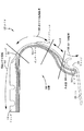
まず、図1を参照すると、環状の組立体の好ましい実施形態の装置10がタイヤ12内に配置されているのが示されている。タイヤ12は、従来の手段によって、ゴムやゴム複合材料のような従来の材料から形成され、ラジアルプライ構成またはバイアスプライ構成を有している。一般的なタイヤ12は、トレッド14、ショルダ16、環状のサイドウォール18、および末端のビード20を有する構成である。インナーライナ22が形成されて、タイヤの空洞24を形成している。タイヤ12は、周縁部のリムフランジ28とリムフランジ外表面30を有する環状のリム26上の位置に取り付けられるようになっている。リム26は、スチールのような適度に強い金属からなり、従来通りの構成である。
Referring first to FIG. 1, a
環状のアンテナ32が設けられており、好ましい実施形態では、正弦曲線状の形状になっている。あるいは、アンテナ32は、他のパターンに構成されていてもよく、また、必要に応じて直線状のワイヤからなっていてもよく、フィラメントワイヤ、あるいはコードすなわち撚られたワイヤであってもよい。許容されるワイヤの材料にはスチール、アルミニウム、銅、またはその他の導電線が含まれる。前述したように、ワイヤの直径は、一般に、アンテナとしての作用にとって重要であるとは考えられておらず、微細なワイヤの複数の撚り線であるのが好ましい。アンテナ32は曲線形状であるため可撓性を有し、後述するように製造中および使用中に破損する可能性が最小限に抑えられる。
An
引き続き図1を参照すると、上述した一般的な種類のトランスポンダモジュール34が設けられており、このトランスポンダモジュール34は、圧力や温度などのタイヤのパラメータを検知する手段を含んでいてもよい。図示するように環状の形状に形成された材料のキャリアストリップ36が、装置10の一部として含まれている。キャリアストリップ36は、ゴムや合成樹脂のような、工業で一般に使用されている、電気絶縁性で、好ましくは半剛性の弾性材料から形成されている。キャリアストリップ36は、アンテナワイヤ32およびトランスポンダモジュール34の少なくとも一部を、後述する方法で実質的に封入するように形成されている。したがって、製造後の状態では、アンテナ32、トランスポンダモジュール34、およびキャリアストリップ36を有する装置10は、容易に移送可能でありタイヤ12に取り付けるための取り扱いが容易な、一体になっている概ね円形で半剛性の組立体である。装置組立体10の直径は、タイヤ12のサイズとタイヤ12上の好ましい取付け位置の関数である。
With continued reference to FIG. 1, there is provided a
図2は、本発明による環状の装置10の、タイヤ12上の好ましい位置を示している。タイヤ12は、従来通りのやり方でリム26に取り付けられている。タイヤ12のビード20は、リム26内に、フランジ28に接するように配置されている。フランジ28の上面30は、タイヤのビード20の下縁部の上方に位置している。理解されるように、フランジ28は、ビード20を有するタイヤ12の下部を遮蔽し、タイヤの「RF干渉」領域38を形成している。さらに、タイヤ12の、RF干渉領域38の上方のサイドウォール18の領域40は「高ひずみ振幅」領域として形成されている。乗物のタイヤの動作時にサイドウォール18が撓むと、領域40は高レベルのひずみを受ける。タイヤ12のトレッド部に位置する領域42を、本明細書では説明のために「圧縮ひずみ」領域と呼ぶ。タイヤ12は、タイヤ12が動作可能な状態で用いられると、領域42において高レベルの圧縮ひずみを受ける。
FIG. 2 shows a preferred position on the tire 12 of the
図1と図2を共に参照すると、装置10は、タイヤ12の製造中に、または好ましくは製造後の組立て工程で、タイヤ12のライナ22に取り付けられる。接着剤によって取付けを行ってもよく、または製造中に装置10をタイヤ12自体に埋め込んでもよい。タイヤ業界でタイヤに継ぎをあてたり修理するのに一般に利用されている接着剤を使用することができる。タイヤ12上の、本発明によって装置10が取り付けられる位置は、図2の、RF干渉領域38と高ひずみ振幅領域40との間に位置する領域44である。RF干渉領域38は、比較的剛性があり、リムフランジ28によって保護されており、タイヤ12の動作中に受けるひずみが比較的低レベルであるので、機械的な観点からは理にかなっていることが理解されるであろう。しかし、リムフランジ28によって遮蔽されている、タイヤ12のRF干渉領域38は、電気的な観点からはトランスポンダモジュール34用の位置として適していない。
Referring to FIGS. 1 and 2 together, the
タイヤサイドウォール18の高ひずみ振幅領域40内の装置10の位置は任意に決められる。このような位置では、リム26によって生じるRF干渉が回避される。しかし、タイヤサイドウォール18は、タイヤの動作中に高レベルのひずみを受ける。その結果、タイヤサイドウォール18に取り付けられている構成部材の損傷や破損が起こるおそれがある。同様に、タイヤ12のトレッド領域42における装置10の位置は、リム26からのRF干渉を回避する位置であるが、トレッド領域42は、タイヤ12の動作中に高レベルの圧縮ひずみを受ける。したがって、タイヤ監視システムの装置がこのような位置にあるのは、機械的な観点から望ましくない。
The position of the
その結果、装置10はタイヤ12の領域44内に位置することが好ましい。領域44は、一般に、タイヤ12がリム26に取り付けられたときにリムフランジ28の上面30より上方の実質的に10ミリメートルから30ミリメートルの間に位置する環状の領域である。装置10は、領域44内では、リム26のリムフランジ28からRF干渉を受けない。さらに、領域44は、タイヤ12の比較的低ひずみ振幅の領域である。したがって、タイヤ12の領域44は、タイヤ12の動作中にタイヤ12に加わるひずみ力による損傷から装置10を機械的に保護しつつ、リム26からのRF干渉を最小限に抑えるという要件のバランスを取る、装置10のための最適な位置に相当する。
As a result, the
図3は、キャリアストリップ36が取り除かれ、アンテナ32およびトランスポンダモジュール34がタイヤ12の製造中にタイヤ12内に直接埋め込まれている、本発明の装置10の参考例を示している。この場合も、アンテナ32の位置は、前段落で最適な位置として説明した領域44内にあり、すなわち、タイヤ12がリム26に取り付けられたときにリムフランジ面30の上方の約10ミリメートルから30ミリメートルの位置である。本発明によるとタイヤ12の製造中に装置10をタイヤ12内に取り付けることが可能であるが、このような方法は、タイヤ12が形成されるときにトランスポンダモジュール34およびアンテナ32が、損傷を与えるおそれのある力に必ずさらされるため好ましくない。さらに、このような力にさらされる環状のアンテナ32およびトランスポンダモジュール34が埋め込まれていると、損傷や破損が起こった場合の組立体の交換および修理に問題が生じる。したがって、製造後の工程で接着剤などによって装置10をタイヤ12に取り付けるのが好ましい。製造後に組立てることの利点は、装置10がタイヤ製造工程の応力を受けず、破損が起こった場合に装置10を容易に取り外して交換できることである。さらに、図1に示されている単体の装置10は、製造前のタイヤまたは使用済みのタイヤに、接着剤によって容易に後から取り付けることができる。最後に、環状の装置10は単一の組立体であり、様々なサイズの製造前のタイヤ12に適合するように、一連の直径の大きさのものを簡便に在庫として保管することができる。
FIG. 3 shows a reference example of the
図4は、タイヤ12上の好ましい位置にありタイヤの空洞24に露出しているトランスポンダモジュール34を示している。トランスポンダモジュール34は、空洞24の状態を監視する圧力センサおよび温度センサを含んでいてもよく、乗物のフレーム46に取り付けられた遠隔トランシーバ48にこのような情報を送信することができる。トランシーバ48は、装置10のアンテナ32と向かい合って位置しており、タイヤ14の360度の回転の間じゅうアンテナ32と連続的に通信する。トランシーバ48は、当該産業界で市販されている種類のトランシーバであり、リード線50によって、乗物の従来の論理電子機器、処理用電子機器、および表示用電子機器(不図示)に電気接続されている。前述したように、トランスポンダモジュール34の位置は、トランスポンダモジュール34とトランシーバ48との間のRF通信を損なわないように、リムフランジ28よりも上方である。
FIG. 4 shows the
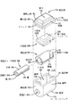
図5〜12を全て参照して、環状の装置10の構成について詳しく説明する。トランスポンダモジュール34は、一般に、従来の手段によってゴムまたは合成樹脂の材料で形成されたベースハウジング52を有している。ベースハウジング52は、丸み付けられた底面55に沿って、互いに向かい合う垂直方向の端部壁58、60に連結されている、互いに向かい合う側壁54、56を含んでいる。壁54、55、56、58、および60は中央室62を形成している。貫通穴64は、端部壁58、60の下部を貫通して延び、中央室62と連通している。
The configuration of the
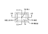
ベースハウジング52は、射出成形のような従来の手段によって従来のゴム材料または合成樹脂材料で従来同様に形成されたキャップ部材68をさらに含んでいる。キャップ部材68は、内側に先細の上部の突出部すなわち「鼻状部」70を含んでいる。センサポートすなわち開口76は、上面74の中央に位置し、その上面74を貫通して延びている。フランジ78は、周縁でキャップ部材68の下側の境界を形成し、水平方向の棚状面80を備えている。キャップ部材68の垂直方向の側壁が、棚状面80から実質的に垂直に延び、平らな上面74に向かって内側に先細になっているキャップ上面81に隣接している。中央のセンサポート76は、上面74を貫通して延びハウジングの中央室62に連通するように配置されている。フランジ78の下面は、トランスポンダモジュールのベースハウジング52上面の上に置かれるような大きさになっており、接合面は一般的な封止材で封止され、ベースハウジング52とキャップ部材68を含む単一のハウジングを形成している。
The
このように、本発明の好ましい実施形態のハウジングは、縦方向に細長い対称形の四辺形であり、上端部に内側向きの階段形状を有している。本発明から逸脱しなければ、ハウジングの、好ましい他の形態および構成を代用して使用することができる。例えば、何ら限定するものではないが、タグハウジングは、もし望まれるならば、または必要であれば、頂部が内側向きの階段形状である弓状の側壁を有する円筒形状や、回路板、トランスポンダセンサ、および/または電子部品を収容する非対称形であってもよい。 As described above, the housing of the preferred embodiment of the present invention is a symmetrical quadrilateral elongated in the vertical direction, and has an inwardly-facing stepped shape at the upper end. Other preferred configurations and configurations of the housing can be used instead without departing from the present invention. For example, without limitation, the tag housing can be a cylindrical shape with an arcuate side wall with a stepped inward-facing top, if desired or necessary, a circuit board, a transponder sensor And / or an asymmetric shape that accommodates electronic components.
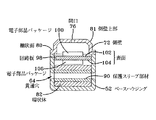
図示されている実施形態では、トランスポンダモジュール34は、高い電磁透過率を有する、フェライトなどの材料からなる環状体(トロイド)82をさらに含んでいる。環状体82は、一般に、楕円形の断面形状を有する円筒を有している。環状体82が楕円形の断面形状であることによって、その垂直方向の寸法が小さくなり、環状体82をトランスポンダモジュール34内に、よりコンパクトにパッケージ可能になる。環状体82は、図示されているように、導電リード線86を終端とする巻線84を含んでいる。中央の貫通穴88は、環状体82を貫通して軸線方向すなわち長手方向に延びている。
In the illustrated embodiment, the
さらに、保護スリーブ部材90が、環状体82の貫通穴88に受け入れられ保持されるような大きさに形成されている。保護スリーブ部材90は、楕円形の断面を有する概ね細長い円筒形を有している。保護スリーブ部材90は、外周部の側壁92と、軸線方向すなわち長手方向の貫通穴94とをさらに含んでいる。貫通穴94は、保護スリーブ部材90の外側に、より厚い壁95を形成するように、保護スリーブ部材90の長手方向の中心軸に対してずれている。図示するように、外側に開放された長手方向の溝96が壁95内に形成されている。保護スリーブ部材90は、環状体82の貫通穴88内に密に受け入れられ、巻線84は、保護スリーブ部材90の溝96内に受け入れられる。
Further, the protective sleeve member 90 is sized to be received and held in the through
引き続き図5〜12を参照すると、回路板98が、トランスポンダモジュール34のベースハウジング52の中央室62内に取り付けられている。回路板98は、通常、上表面102に取り付けられた電子部品パッケージ100を有する構成であり、下面104に取り付けられた電子部品パッケージ106を含んでいてもよい。電子部品パッケージ100、106は、図5〜12に概略的に示されており、タイヤの空洞の監視活動を行うのに必要なトランスポンダセンサシステム、論理システム、およびRF送信システムを含んでいる。本発明は、トランスポンダの構成に固有のものではなく、多数の従来のトランスポンダシステムのうちの任意のシステムが利用でき、それを回路板98の表面102、104の一方または両方に取り付けることができる。回路板98は、回路板98の側面に形成されている、リード線を受け入れる溝108をさらに含んでいる。
With continued reference to FIGS. 5-12, a circuit board 98 is mounted within the
トランスポンダモジュール34の組立は一般に以下のように進行する。保護スリーブ部材90を環状体82の貫通穴88内に挿入し、次に、環状体82をベースハウジング52の中央室62内に挿入する。中央室62内に置かれると、保護スリーブ部材90の貫通穴94と環状体82の貫通穴88は、貫通穴64を通ってベースハウジング52と同軸に整列する。環状体82の巻線84は保護スリーブ部材90の溝96内に受け入れられ、リード線86は上方に向けられる。巻線84は、従来通りのやり方でトランスポンダ電子機器のインピーダンスを整合させるような巻数に構成されている。好ましい実施形態では、回路板98を、ベースハウジング52内に、通路を貫通する保護スリーブ部材90および環状体82の上方に水平に取り付ける。巻線84からのリード線86を溝108内を通し、回路板98上の電子部品パッケージ100、106と電気接続する。その後、キャップ部材68の周縁のフランジ78をベースハウジング52の上面66上に位置させ、適切な接着剤を塗布することによって接合面を封止する。
The assembly of the
組立状態では、トランスポンダモジュール34は図7に示されている状態になる。トランスポンダモジュール34のハウジング、内部組立体、および構成部材の向きは、本発明を実施する際に望まれるならば変えることができる。したがって、トランスポンダモジュール34は、回路板98と、圧力や温度などのタイヤ空洞のパラメータを監視するトランスポンダ電子機器とを含む、密封された、必要なものを全て内蔵したユニットからなる。トランスポンダモジュール34の電子機器は、さらにタイヤ識別情報を含んでいてもよい。環状体82は、巻線84によって、トランスポンダモジュール34に電磁的かつ機械的に結合している。
In the assembled state, the
アンテナ32は、図5から最も良く分かるようにトランスポンダモジュール34を貫通して延び、連続的なループを構成する。好ましい実施形態のアンテナ32は正弦曲線形状に形成されており、この正弦曲線形状は、タイヤ12の動作によるタイヤ12内のひずみ力に対抗するようにアンテナ32を伸ばすことができるようにするために役立つ。アンテナ32は、保護スリーブ部材90の貫通穴94、環状体82の貫通穴88、およびハウジング52の貫通穴64を、接触しないように貫通して突出している。したがって、アンテナ32はトランスポンダモジュール34に機械結合されていないが、電磁的に結合されている。環状体82は、一次巻線が取り除かれた変成器として働くことに留意されたい。アンテナループ32は、環状体82の貫通穴88を直接貫通して通過し、一次巻線のない環状体82に磁気結合されている。トランシーバ48の磁界のためにアンテナループ32に生じる電流によってアンテナループ32の近くに磁気が発生するため、アンテナループ32と環状体82の間、したがって巻線84内に電気結合が生じる。磁界は、アンテナループ32のワイヤを密に取り囲む環状体82内に直接発生する。
The
本明細書で直接磁気結合(DMC)と呼ばれるこのような結合は、いくつかの異なる利点をもたらす。DMC手法は、アンテナループ32が機械的に接続されることなく、トランスポンダパッケージを通過できるようにし、したがって、ループワイヤとトランスポンダパッケージを接続しその接続を維持することに伴う前述した問題を解消する。巻線84の巻数比は、最適なインピーダンス整合に適合するように変えることができる。第2に、DMC技術は高エネルギー結合をもたらす。さらに、アンテナループ32をトランスポンダモジュール34に取り付ける工程が簡略化され、ワイヤ束すなわちケーブルとトランスポンダモジュール34を離れた状態で結合することがかなり容易になる。さらに、DMC技術を用いた環状のアンテナ32とトランスポンダモジュール34との磁気結合は、360度に亘る連続的な読取りのあいだ維持され、呼び掛け領域内の不感域が回避される。好ましいアンテナと変成器の直接磁気結合が本実施形態に示されているが、直接結合は、本発明の必須の実施形態ではない。必要であれば、巻線またはその他の公知技術を用いてアンテナを変成器に結合してもよい。
Such coupling, referred to herein as direct magnetic coupling (DMC), provides several different advantages. The DMC approach allows the
好ましくはないが、図5の組立体はタイヤ12の製造中にタイヤ12に埋め込むことができ、その結果、図3に示されているタイヤ組立体が得られる。タイヤ12の組立中に環状の装置10を組み込むと、タイヤ12を監視する部材にかなり大きなひずみが加えられ、その部材が破損するおそれがある。硬化後の状態では、環状の組立体または組立体内の任意の構成部材を取り外すことは困難であるかまたは不可能である。したがって、本発明の環状の組立体は、タイヤ組立後の工程でタイヤ12に取り付けるのが好ましい。
Although not preferred, the assembly of FIG. 5 can be embedded in the tire 12 during manufacture of the tire 12, resulting in the tire assembly shown in FIG. If the
そうするために、まず、アンテナ32とトランスポンダモジュール34の半組立体を、図1および6に示されている剛性または半剛性のキャリアストリップ36内に埋め込む。キャリアストリップ36は、ゴムや合成樹脂のような非導電性の密封材料から形成されており、その結果、単体で、移送、保管、および取り扱いが容易な環状の組立体が得られる。アンテナ32とトランスポンダモジュール34とキャリアストリップ36を一体に組合せたものを形成することによって、タイヤ組立後の工程で環状の組立体をタイヤに組み込むのが容易になる。環状の組立体を、前述した最適な領域44内の位置でタイヤのライナ22に接するように配置する。市販の接着剤を塗布することによってキャリアストリップ36をタイヤに接着する。万一、搬送時または誤動作時にアンテナ32とトランスポンダモジュール34が破損した場合には、タイヤ12を損傷させずに組立体10を取り外して交換することができる。さらに、密封材料は、アンテナ32および環状体の互いの向きを所望の向きに維持する働きをする。
To do so, the
トランスポンダモジュール34をキャリアストリップ36に前もって容易に組み込めるように、キャップ部材68およびベースハウジング52を含むトランスポンダモジュール34のハウジングは、階段状で先細の固有の形状を有している。キャップ部材68は、内側に先細の表面81によって形成された上端部に、先細の鼻状部70を有している。キャップ部材68は、下方の周縁部のフランジ78で、外側に階段状になっている。図7および11を見ると最も良く分かるように、ハウジングの鼻状部70は、金型ブロック110内のキャビティ112内に受け入れられる。この先細形状によって、トランスポンダモジュール34のハウジングは自ら位置合わせし、キャリアストリップ36の材料が導入される前に、ハウジングはキャビティ112内で中心合わせされる。金型ブロック110の側壁114は、中心合わせされた位置でキャップ表面72に密に当接し、金型ブロック110の下面115はキャップフランジ78の上面80に当接して、キャップ部材68の鼻状部70を金型のキャビティ112内で非接触状態にして保護する。ハウジングの当接面と金型ブロックの間に形成されている曲がりくねった経路は、導入されたキャリアストリップの材料の、キャビティ内への、センサポート76の下方への、およびハウジングの中央室62内への進行を抑止する。金型ブロック110の下半分(図11には示されていない)は、金型ブロック110の下面115に対して近接し、キャリアストリップ36を形成する材料が金型のキャビティ112に導入される。当接面114、115とキャップ表面72、80が、キャリアストリップ36の材料がキャビティ112に進入し、次にトランスポンダの開口76に進入するのを防止する。本実施形態で示しているように、キャリアストリップ36を形成する材料は、フランジ78の表面80まで充填され、アンテナ32を完全に封入するとともに、トランスポンダモジュール34のベースハウジング52を部分的に封入する。しかし、ハウジングとアンテナ32がキャリアストリップ36内に封入される程度は、もしも望まれるならばまたは必要であれば、変更可能である。
The
金型の2つの半分部を分離し、一体的に取り込まれたアンテナ32およびトランスポンダモジュール34とともに環状のキャリアストリップ36を金型から取り外す。その後、本発明の環状の組立体を、すでに説明したやり方で、図1および6に示すようにタイヤ12のインナーライナ22に取り付ける。トランスポンダモジュール34は、図3に示されているようにキャリアストリップ36に対して平らな向きにしても、符号34’を付与され破線で示されているように直立する向きにしてもよい。どちらの向きを採用しても、ストリップ材料36は、トランスポンダモジュール34およびアンテナ32を好ましい最適な相互の向きに維持し、トランスポンダモジュール34をタイヤ12の空洞24に対して最適な向きに維持する働きをする。キャップ部材68の上面74のポート76は、開口して空洞24に露出し、キャリアストリップ36の制約を受けずに突出した状態に維持されている。それによって、タイヤ12の空洞24と、回路板98に取り付けられたセンサは、ポート76を通して容易に直接連通する。トランスポンダモジュール34の階段状で先細の形状は、トランスポンダモジュール34が自ら中心合わせし、金型とトランスポンダモジュール34の外面との間を確実に封止できるようにするために好ましい。棚状面80および垂直方向の表面と、キャップ部材68の側壁72と、金型の側壁の内側を向いた面114との間に形成されている環状の経路は、キャリアストリップ36の材料がキャビティ112内へ流れるのを妨げる。材料の流れが抑止されない場合、その材料は、キャビティ112に入りポート76を通って回路板90まで流れる可能性がある。したがって、回路板98上に取り付けられた電子機器およびセンサは、トランスポンダモジュール34のベースハウジング52の周りにキャリアストリップ36を成形する工程の間、トランスポンダモジュール34のハウジングの階段状の形状によって保護される。
The two halves of the mold are separated and the
図14は、トランシーバ、トランスポンダ、およびアンテナシステムの概略図を示している。 FIG. 14 shows a schematic diagram of a transceiver, transponder, and antenna system.
以上の説明から、図示している実施形態は、トランスポンダと変成器を環状のタイヤ監視システム内に収容する公知のシステムおよび方法の欠点を克服することが理解されるであろう。図示している実施形態によれば、タグハウジングは、アンテナとタグハウジングを一体的に搬送できるようにリング状の組立体を形成する非導電性のキャリアストリップに少なくとも部分的に埋め込まれている。キャリアストリップはさらに、アンテナループおよびトランスポンダの構成部材を完全な状態に保つ働きをする。このような組立体は、タイヤの製造工程中にタイヤに組み込んでもよいが、好ましくは製造後の取付け工程において、接着剤または他の公知の方法によってタイヤに取り付けられる。キャリアストリップは、それに封入されたアンテナワイヤおよびトランスポンダを完全な状態に保ち、必要に応じて、既存のタイヤに監視システムを後から取り付けるか、または欠陥のある構成部材を交換するために、うまい具合に移送し、保管し、設置することのできる単一の組立体を形成し、アンテナを、それが貫通して延びるトランスポンダの環状体に対して最適な関係に維持し、トランスポンダをタイヤの空洞に対して最適な向きにするのを容易にするように働く。 From the foregoing description, it will be appreciated that the illustrated embodiment overcomes the shortcomings of known systems and methods for housing transponders and transformers within an annular tire monitoring system. According to the illustrated embodiment, the tag housing is at least partially embedded in a non-conductive carrier strip that forms a ring-like assembly so that the antenna and tag housing can be carried together. The carrier strip further serves to keep the antenna loop and transponder components intact. Such an assembly may be incorporated into the tire during the manufacturing process of the tire, but is preferably attached to the tire by an adhesive or other known method in the post-manufacturing mounting process. The carrier strip is perfect for keeping the antenna wires and transponders enclosed in it intact and, if necessary, retrofitting the existing tire with a monitoring system or replacing defective components. A single assembly that can be transported, stored, and installed, maintaining the antenna in an optimal relationship with respect to the transponder annulus through which it extends and the transponder into the tire cavity It works to make it easier to get the optimal orientation.
本発明によれば、タグハウジングは、環状の装置の製造および組立における利点をもたらす階段状の細長い形状を有している。このタグハウジングの構成によって、タグハウジングは金型内で自ら中心合わせし、かつ金型ブロックの側壁に当接して、キャリアストリップの材料が金型ブロックのキャビティ内に流れ込むのを妨げる傾斜した側面が形成される。それによって、ハウジング鼻状部の上面を貫通するセンサポートは開口して動作可能な状態に維持され、損傷を生じさせる可能性のある、ハウジングの室内のキャリアストリップの材料とトランスポンダの接触が回避される。 In accordance with the present invention, the tag housing has a stepped elongated shape that provides advantages in the manufacture and assembly of annular devices. With this tag housing configuration, the tag housing is centered itself in the mold and abuts against the side wall of the mold block to provide an inclined side surface that prevents the carrier strip material from flowing into the cavity of the mold block. It is formed. Thereby, the sensor port that penetrates the top surface of the housing nose is kept open and operable, avoiding contact between the carrier strip material and the transponder in the housing chamber, which can cause damage. The
10 環状の装置(組立体)
12 タイヤ
14 トレッド
16 ショルダ
18 サイドウォール
20 ビード
22 インナーライナ
24 空洞
26 リム
28 リムフランジ
30 外表面
32 アンテナ
34 トランスポンダモジュール
36 キャリアストリップ
38 RF干渉領域
40 高ひずみ振幅領域
42 圧縮ひずみ領域
44 領域
46 フレーム
48 トランシーバ
50 リード線
52 ベースハウジング
54、56 側壁
55 底面
58、60 壁
62 中央室
68 キャップ部材
70 鼻状部
72 側壁
74 上面
76 開口(ポート)
78 フランジ
80 棚状面
81 側壁上部
82 環状体
84 巻線
86 導電リード線
88 貫通穴
90 保護スリーブ部材
92 側壁
94 貫通穴
95 壁
96 溝
98 回路板
100 電子部品パッケージ
102、104 表面
106 電子部品パッケージ
110 金型ブロック
112 キャビティ
114 側壁
115 下面
10 Annular device (assembly)
12
78 Flange 80 Shelf surface 81 Side wall
Claims (3)
該環状の組立体(10)は、前記空気圧を監視するためのトランスポンダ電子機器を収容しているタグハウジングと、前記タグハウジングを囲んで前記タイヤ内に固定され該タグハウジングを支持しているキャリアストリップ(36)とを含み、
前記タグハウジングは、互いの間に内部室(62)を形成している、互いに向かい合う側壁(54,56)および底壁(55)と、上部フランジ面(80)を有するフランジ(78)と、前記上部フランジ面(80)の上方に配置され、前記上部フランジ面(80)に対して所定の角度で交差する側壁の第1部分(72)と、上面(74)まで延び、前記上面(74)と共にハウジング鼻状部(70)を形成する側壁上部の収束部(81)と、前記上面(74)を通って延び前記内部室(62)と連通する入口部(76)と、を有し、前記フランジ(78)は、前記ハウジング鼻状部(70)の前記側壁の第1部分(72)から前記タグハウジングの周縁部まで外側に突出している
環状の組立体。 An annular assembly (10) housed in a tire (12) for monitoring the air pressure inside the tire (12),
The annular assembly (10) includes a tag housing that houses the transponder electronics for monitoring the air pressure, and a carrier that surrounds the tag housing and is fixed within the tire to support the tag housing. A strip (36),
The tag housing includes a flange (78) having opposing side walls (54, 56) and a bottom wall (55), and an upper flange surface (80) forming an internal chamber (62) therebetween. A first portion (72) of a side wall disposed above the upper flange surface (80) and intersecting the upper flange surface (80) at a predetermined angle, extends to the upper surface (74), and extends to the upper surface (74). ) And a converging portion (81) at the upper side wall forming a housing nose-like portion (70), and an inlet portion (76) extending through the upper surface (74) and communicating with the inner chamber (62). The flange (78) protrudes outward from the first portion (72) of the side wall of the housing nose (70) to the peripheral edge of the tag housing.
The annular assembly according to claim 2, wherein the tag housing is embedded in the carrier strip (36) up to the flange (78) at the periphery.
Applications Claiming Priority (1)
| Application Number | Priority Date | Filing Date | Title |
|---|---|---|---|
| US39806502P | 2002-07-24 | 2002-07-24 |
Publications (3)
| Publication Number | Publication Date |
|---|---|
| JP2004069694A JP2004069694A (en) | 2004-03-04 |
| JP2004069694A5 JP2004069694A5 (en) | 2006-09-07 |
| JP4458790B2 true JP4458790B2 (en) | 2010-04-28 |
Family
ID=32030614
Family Applications (1)
| Application Number | Title | Priority Date | Filing Date |
|---|---|---|---|
| JP2003279084A Expired - Fee Related JP4458790B2 (en) | 2002-07-24 | 2003-07-24 | Annular assembly |
Country Status (4)
| Country | Link |
|---|---|
| EP (1) | EP1384602B1 (en) |
| JP (1) | JP4458790B2 (en) |
| BR (1) | BR0302382A (en) |
| DE (1) | DE60305803T2 (en) |
Cited By (1)
| Publication number | Priority date | Publication date | Assignee | Title |
|---|---|---|---|---|
| JP2012027022A (en) * | 2010-07-22 | 2012-02-09 | Robert Bosch Gmbh | Pressure sensor and method for manufacturing pressure sensor |
Families Citing this family (4)
| Publication number | Priority date | Publication date | Assignee | Title |
|---|---|---|---|---|
| JP4204833B2 (en) * | 2002-09-25 | 2009-01-07 | 株式会社ブリヂストン | tire |
| WO2007049093A1 (en) | 2005-10-28 | 2007-05-03 | Pirelli Tyre S.P.A. | A tyre comprising an electronic unit and a method of installing said electronic unit into said tyre |
| TWM526197U (en) * | 2016-02-23 | 2016-07-21 | 莊秀萍 | Transmitter for wireless tire pressure monitoring system |
| JP2019098852A (en) * | 2017-11-30 | 2019-06-24 | 株式会社ブリヂストン | Function component mounting pedestal, function component and tire |
Family Cites Families (6)
| Publication number | Priority date | Publication date | Assignee | Title |
|---|---|---|---|---|
| US5119066A (en) * | 1988-06-06 | 1992-06-02 | Jan Ballyns | Pressure sensor system |
| AU5692798A (en) * | 1997-12-09 | 1999-06-28 | Goodyear Tire And Rubber Company, The | Antenna for radio transponder |
| US6161430A (en) * | 1998-10-16 | 2000-12-19 | Bridgestone/Firestone Research Inc. | Device to encapsulate a substrate containing sensitive electronic components and a pressure sensor pack |
| US6016102A (en) * | 1999-01-29 | 2000-01-18 | Eaton Corporation | Pressure sensor housing |
| US6357833B1 (en) * | 1999-07-12 | 2002-03-19 | Smartire Systems, Inc. | Wheel component with cavity for mounting a housing for measurement apparatus |
| DE10154494A1 (en) * | 2001-11-08 | 2003-05-22 | Continental Ag | Transmitting and / or receiving device for installation in elastic structures and antennas therefor |
-
2003
- 2003-07-10 BR BR0302382-6A patent/BR0302382A/en not_active Application Discontinuation
- 2003-07-16 DE DE60305803T patent/DE60305803T2/en not_active Expired - Fee Related
- 2003-07-16 EP EP03102181A patent/EP1384602B1/en not_active Expired - Fee Related
- 2003-07-24 JP JP2003279084A patent/JP4458790B2/en not_active Expired - Fee Related
Cited By (1)
| Publication number | Priority date | Publication date | Assignee | Title |
|---|---|---|---|---|
| JP2012027022A (en) * | 2010-07-22 | 2012-02-09 | Robert Bosch Gmbh | Pressure sensor and method for manufacturing pressure sensor |
Also Published As
| Publication number | Publication date |
|---|---|
| EP1384602B1 (en) | 2006-06-07 |
| EP1384602A1 (en) | 2004-01-28 |
| DE60305803D1 (en) | 2006-07-20 |
| JP2004069694A (en) | 2004-03-04 |
| DE60305803T2 (en) | 2006-11-23 |
| BR0302382A (en) | 2004-08-24 |
Similar Documents
| Publication | Publication Date | Title |
|---|---|---|
| JP4585183B2 (en) | Annular antenna and transponder device and method for placing them in a pneumatic tire | |
| US7019711B2 (en) | Coupled transponder and antenna system and method | |
| US6772505B1 (en) | Method of assembly an annular antenna to a transponder | |
| JP4763401B2 (en) | Mounting method of annular tire transponder assembly that also serves as counterbalance | |
| CN110072713B (en) | Pneumatic tire equipped with electronic component | |
| JP4630035B2 (en) | Method for integrating tire identification data and OEM vehicle identification data | |
| KR100817741B1 (en) | Dipole antenna for tire tag | |
| CN110035913B (en) | Pneumatic tire equipped with electronic component | |
| JP4014322B2 (en) | Method and apparatus for transmitting accumulated data and engineering conditions on tires to remote locations | |
| EP0925958B1 (en) | Method and apparatus for monitoring conditions of a vehicle tire | |
| US8142600B2 (en) | Method for mounting a tag in a tire sidewall | |
| EP1657083A2 (en) | Method of assembly of an annular wire antenna and a transponder apparatus | |
| JP4458790B2 (en) | Annular assembly | |
| US20230161993A1 (en) | Antenna connection for integrated rfid tag and tpms sensor |
Legal Events
| Date | Code | Title | Description |
|---|---|---|---|
| A521 | Written amendment |
Free format text: JAPANESE INTERMEDIATE CODE: A523 Effective date: 20060721 |
|
| A621 | Written request for application examination |
Free format text: JAPANESE INTERMEDIATE CODE: A621 Effective date: 20060721 |
|
| A977 | Report on retrieval |
Free format text: JAPANESE INTERMEDIATE CODE: A971007 Effective date: 20090423 |
|
| A131 | Notification of reasons for refusal |
Free format text: JAPANESE INTERMEDIATE CODE: A131 Effective date: 20090427 |
|
| A601 | Written request for extension of time |
Free format text: JAPANESE INTERMEDIATE CODE: A601 Effective date: 20090727 |
|
| A602 | Written permission of extension of time |
Free format text: JAPANESE INTERMEDIATE CODE: A602 Effective date: 20090730 |
|
| A521 | Written amendment |
Free format text: JAPANESE INTERMEDIATE CODE: A523 Effective date: 20090731 |
|
| A131 | Notification of reasons for refusal |
Free format text: JAPANESE INTERMEDIATE CODE: A131 Effective date: 20090915 |
|
| A521 | Written amendment |
Free format text: JAPANESE INTERMEDIATE CODE: A523 Effective date: 20091215 |
|
| TRDD | Decision of grant or rejection written | ||
| A01 | Written decision to grant a patent or to grant a registration (utility model) |
Free format text: JAPANESE INTERMEDIATE CODE: A01 Effective date: 20100113 |
|
| A01 | Written decision to grant a patent or to grant a registration (utility model) |
Free format text: JAPANESE INTERMEDIATE CODE: A01 |
|
| A61 | First payment of annual fees (during grant procedure) |
Free format text: JAPANESE INTERMEDIATE CODE: A61 Effective date: 20100209 |
|
| R150 | Certificate of patent or registration of utility model |
Free format text: JAPANESE INTERMEDIATE CODE: R150 |
|
| FPAY | Renewal fee payment (event date is renewal date of database) |
Free format text: PAYMENT UNTIL: 20130219 Year of fee payment: 3 |
|
| LAPS | Cancellation because of no payment of annual fees |