JP3992488B2 - Liquid processing apparatus and liquid processing method - Google Patents

Liquid processing apparatus and liquid processing method Download PDF

Info

Publication number
JP3992488B2
JP3992488B2 JP2001378543A JP2001378543A JP3992488B2 JP 3992488 B2 JP3992488 B2 JP 3992488B2 JP 2001378543 A JP2001378543 A JP 2001378543A JP 2001378543 A JP2001378543 A JP 2001378543A JP 3992488 B2 JP3992488 B2 JP 3992488B2
Authority
JP
Japan
Prior art keywords
chamber
cleaning
processing
liquid
wafer
Prior art date
Legal status (The legal status is an assumption and is not a legal conclusion. Google has not performed a legal analysis and makes no representation as to the accuracy of the status listed.)
Expired - Fee Related
Application number
JP2001378543A
Other languages
Japanese (ja)
Other versions
JP2002246361A (en
JP2002246361A5 (en
Inventor
裕二 上川
太一 坂口
Current Assignee (The listed assignees may be inaccurate. Google has not performed a legal analysis and makes no representation or warranty as to the accuracy of the list.)
Tokyo Electron Ltd
Original Assignee
Tokyo Electron Ltd
Priority date (The priority date is an assumption and is not a legal conclusion. Google has not performed a legal analysis and makes no representation as to the accuracy of the date listed.)
Filing date
Publication date
Application filed by Tokyo Electron Ltd filed Critical Tokyo Electron Ltd
Priority to JP2001378543A priority Critical patent/JP3992488B2/en
Publication of JP2002246361A publication Critical patent/JP2002246361A/en
Publication of JP2002246361A5 publication Critical patent/JP2002246361A5/ja
Application granted granted Critical
Publication of JP3992488B2 publication Critical patent/JP3992488B2/en
Anticipated expiration legal-status Critical
Expired - Fee Related legal-status Critical Current

Links

Images

Description

【0001】
【発明の属する技術分野】
本発明は、半導体ウエハやLCD基板等の各種基板に対して液処理や乾燥処理を施す液処理装置と液処理方法に関する。
【0002】
【従来の技術】
例えば、半導体デバイスの製造工程においては、基板としての半導体ウエハを所定の薬液や純水等によって洗浄することによって、ウエハからパーティクル、有機汚染物、金属不純物等のコンタミネーション、エッチング処理後のポリマー等を除去するウエハ洗浄装置や、窒素(N)ガス等の不活性ガスや揮発性および親水性の高いIPA蒸気等によってウエハから液滴を取り除いてウエハを乾燥させるウエハ乾燥装置が使用されている。
【0003】
このような洗浄・乾燥装置としては、複数枚のウエハをバッチ式に処理するものが知られており、例えば、複数枚のウエハがその主面が略平行になるようにして収容された容器を洗浄・乾燥装置の所定位置に載置し、搬送機構を用いてこの容器内に収容された複数のウエハを同時に取り出して、ウエハを保持するロータに移し替え、チャンバ内においてロータに保持されたウエハに所定の液処理と乾燥処理を施した後に、再び搬送機構を用いて容器へウエハを搬送するという作業が行われる。
【0004】
ここで洗浄から乾燥に至る工程については、薬液を用いた薬液処理の後にIPAを用いて薬液を洗い流し、次いで純水を用いた水洗処理を行い、最後にIPA蒸気やNガス乾燥処理を行うという処理工程が一般的に用いられている。
【0005】
【発明が解決しようとする課題】
しかしながら、近年、このような一連の処理工程において、IPAによって薬液を洗い流す処理工程を省いて処理工程を短縮し、スループットを向上させたいという要望や、IPAを使用しないようにすることで処理コストを低減させたいという要望が大きくなっている。ところが、薬液処理の後にはチャンバの内壁等に薬液が付着しており、またチャンバ底部にも薬液が完全には排出されずにある程度の量が残留しているために、このような状態で薬液処理の後に水洗処理を行うと、薬液が純水により希釈されることによって、例えば、強アルカリ性水溶液が生成する。この強アルカリ性水溶液がチャンバ内にある程度長い時間存在すると、ウエハがダメージを受けるおそれがある。
【0006】
また、一般的に、液処理を行う処理空間を形成するチャンバは液処理中には処理液が外部に飛散しないようにシール構造を有し、このシール部についてはゴム等のシール材が用いられることが一般的である。このようなシール材は薬液等による劣化や経時的な劣化が生ずるために突発的にまたは定期的に交換する必要が生じるが、従来の液処理装置では、シール材を交換するためにチャンバ自体を取り外さなければならない等、作業性やメンテナンス性は必ずしも良いものではなかった。
【0007】
さらに、薬液処理や乾燥処理時において、基板の主面のパーティクル付着量が少なく、薬液滴等の痕跡が残り難いようにすることにより、基板の品質を高く保持し、信頼性を高めることが求められているが、未だ十分とは言えない。
【0008】
本発明はこのような事情に鑑みてなされたものであり、処理液が混合されることによって基板に損傷が生ずることを防止した液処理装置と液処理方法を提供することを目的とする。また本発明は、異なる処理液の混合を防止するために中間的に使用されていた処理液を使用することなく液処理を行うことを可能とする液処理装置を提供することを目的とする。
【0009】
【課題を解決するための手段】
上記課題を解決するために、本発明の第1の観点によれば、複数の基板に処理液を供給して液処理を行う液処理装置であって、前記複数の基板を所定間隔で保持可能なロータと、前記複数の基板に対して処理を行う処理位置と、この処理位置とは別の位置にある退避位置との間でスライド自在に設けられ、前記処理位置において前記ロータを収容する処理室を形成するチャンバと、前記処理室内に収容された基板に前記処理液を吐出する処理液吐出ノズルと、前記チャンバを洗浄するクリーニング機構と、を具備し、前記クリーニング機構は、前記チャンバが前記退避位置にあるときに、前記チャンバとの間で洗浄処理室を形成するように設けられた洗浄処理室形成用部材と、前記洗浄処理室に洗浄液を吐出する洗浄液吐出ノズルと、前記洗浄処理室に乾燥用ガスを吐出するガス吐出ノズルと、
を有することを特徴とする液処理装置、が提供される。
【0010】
本発明の第2の観点によれば、固定して設けられた略筒状の外側チャンバと、前記外側チャンバの内部にある処理位置と、前記外側チャンバの外側にある退避位置との間でスライド自在に設けられた略筒状の内側チャンバと、前記内側チャンバが前記退避位置にあるときに、前記内側チャンバとの間で洗浄処理室を形成するように設けられた洗浄処理室形成用部材を有し、前記内側チャンバを前記退避位置において洗浄するクリーニング機構と、を具備した液処理装置を用いて、複数の基板を所定間隔で保持可能なロータに保持された基板に処理液を供給して液処理を行う液処理方法であって、前記処理位置において前記内側チャンバを用いて前記基板の液処理を行う第1工程と、前記内側チャンバを退避させた後に前記外側チャンバを用いて前記基板の液処理を行う第2工程と、前記クリーニング機構による前記内側チャンバの洗浄処理を前記退避位置において所定のタイミングで行う第3工程と、を有することを特徴とする液処理方法、が提供される。
【0011】
このような液処理装置と液処理方法によれば、チャンバのクリーニング機構が設けられているために、複数の処理液を連続して用いる液処理を行う場合において、ある処理液に対してその前段で使用された処理液が混入することが好ましくないときには、処理液を変えて液処理を行う前にチャンバの洗浄を行うことができる。これにより処理液のコンタミネーションの発生が防止され、処理液の特性を引き出して精度の高い液処理を行うことが可能となり、ひいては基板の品質を高く保持することが可能となる。
【0012】
なお、チャンバとして内側チャンバと外側チャンバとからなる二重構造を有するチャンバを用いた場合には、一方のチャンバを用いて処理液による液処理を行った後に、他方のチャンバを用いて別の処理液による液処理を行うことができる。これによって処理液の混合を防止することが可能であり、また、スループットを向上させることができる。しかしながら、この場合には、あるバッチの基板について一連の処理が終了した後に、次のバッチの基板について液処理を開始するにあたって、最初に使用された一方のチャンバを清浄な状態に戻しておかなければならないという新たな問題が生ずる。本発明の液処理装置は、クリーニング機構を有していることから、このような二重構造を有するチャンバを用いることによって生ずる新たな問題をも解決することが可能であり、スループットの向上のみならず、処理コストの低減にも効果を奏する。
【0013】
【発明の実施の形態】
以下、添付図面を参照しながら本発明の実施の形態について具体的に説明する。本発明の1つである液処理装置は、例えば、各種基板を被処理体とする洗浄処理装置や乾燥処理装置等に適用できるが、本実施形態においては、半導体ウエハ(ウエハ)の搬送、洗浄、乾燥をバッチ式に一貫して行うように構成された洗浄処理装置を例として説明することとする。
【0014】
図1は洗浄処理装置1の外観を示す斜視図である。図1に示されるように、洗浄処理装置1は、複数枚のウエハWを収容可能なフープ(Front Opening Unified Pod)Fを載置するためのフープステージ2a〜2cが設けられたフープ搬入出部2と、ウエハWに対して洗浄処理を実施する洗浄処理ユニット3と、フープ搬入出部2と洗浄処理ユニット3との間に設けられ、ウエハWの搬送を行うウエハ搬送ユニット4と、洗浄処理のための薬液を貯蔵等する薬液貯蔵ユニット5から主に構成されている。
【0015】
また、洗浄処理装置1に設けられた各種の電動駆動機構や電子制御装置のための電源ボックス6と、洗浄処理装置1を構成する各ユニットの温度制御を行うための温度制御ボックス7が洗浄処理ユニット3の上部に設けられており、ウエハ搬送ユニット4の上部には、洗浄処理装置1に設けられた各種の表示パネルを制御する表示ボックス9と、ウエハ搬送ユニット4に設けられたウエハ搬送機構16の制御装置が収容された搬送機構制御ボックス10が設けられている。また、薬液貯蔵ユニット5の上部には各ボックスからの熱排気を集めて排気する熱排気ボックス8が設けられている。
【0016】
図2に洗浄処理装置1の概略平面図を、図3に洗浄処理装置1の概略側面図を、図4に図3の概略側面図において一部の駆動機構を駆動させた状態を示した概略側面図をそれぞれ示す。ここで図2〜図4においては、フープ搬入出部2、洗浄処理ユニット3、ウエハ搬送ユニット4、薬液貯蔵ユニット5のみを示し、洗浄処理ユニット3、ウエハ搬送ユニット4、薬液貯蔵ユニット5の上部に設けられた電源ボックス6その他各種のボックス部については図示していない。また、後述するように、洗浄処理ユニット3は搬送部3aと洗浄部3bとに分けられるが、図3および図4においては、搬送部3aの概略構造が示されている。
【0017】
フープステージ2a〜2cに載置されるフープFは、ウエハWを複数枚、例えば25枚を所定間隔で主面が水平になるように収容することが可能となっており、フープFの一側面にはウエハWを搬入出するためのウエハ搬入出口が設けられている。フープFはウエハ搬入出口を開閉する蓋体11を有しており、この蓋体11は、後述する蓋体開閉機構15a〜15cによってフープFに脱着可能となっている。
【0018】
ウエハ搬送ユニット4とフープ搬入出部2との間の境界壁12には窓部12a〜12cが設けられており、フープFに形成されたウエハ搬入出口の外周部が窓部12a〜12cを閉塞し、また、蓋体11が蓋体開閉機構15a〜15cによって脱着可能な状態となるようにして、フープFはフープステージ2a〜2c上に載置される(図4参照)。
【0019】
境界壁12の内側(ウエハ搬送ユニット4側)には、窓部12a〜12cのそれぞれの位置に、窓部12a〜12cを開閉するシャッター13a〜13cとシャッター13a〜13cを昇降させる昇降機構14a〜14cからなる蓋体開閉機構15a〜15cが設けられている。蓋体開閉機構15a〜15cは図示しない吸着パッド等の蓋体把持手段を有しており、これによりフープFの蓋体11をシャッター13a〜13cとともに昇降させることができるようになっている。
【0020】
フープFがフープステージ2a〜2cに載置されていないときには、シャッター13a〜13cが窓部12a〜12cを閉塞した状態にあるため、外部からウエハ搬送ユニット4へのパーティクル等の侵入が防止される。一方、ウエハWをフープFから搬出し、またはフープFへ搬入する際には、後述するウエハ搬送機構16の搬送用ピック17a・17bがフープFにアクセスできるように、シャッター13a〜13cおよびフープFの蓋体11が蓋体開閉機構15a〜15cにより降下され、窓部12a〜12cは開口した状態とされる。
【0021】
ウエハ搬送ユニット4には、蓋体開閉機構15a〜15cのそれぞれに隣接して、フープF内のウエハWの枚数を計測するためのウエハ検査機構110が設けられている。このウエハ検査機構110は、例えば、赤外線レーザを用いた発信部と受信部を有する反射式光センサ111を有している。モータ113を用いてガイド112に沿ってこの反射式センサ111をZ方向(鉛直方向)にスキャンさせながら、ウエハWに向けて赤外線レーザを発振しながらウエハWの端面からの反射光を受信する。これによりフープFに収容されたウエハWの枚数や収容状態、例えば、ウエハWが所定のピッチで略平行に1枚ずつ収容されているかどうか、2枚のウエハWが重なって収容されていないかどうか、ウエハWが段差ずれして斜めに収容されていないかどうか、ウエハWがフープF内の所定位置から飛び出していないかどうか等を検査することができるようになっている。
【0022】
なお、ウエハ搬送機構16にウエハ検査機構110を取り付けて、ウエハ検査機構110をウエハ搬送機構16とともに移動可能な構造とすれば、ウエハ検査機構110は1カ所のみに設ければよい。また、例えば、ウエハWの収容枚数を確認するセンサと、ウエハWの収容状態を検査するセンサを別に設けることもできる。さらに、蓋体開閉機構15a〜15cにウエハ検査機構110を取り付けてもよい。
【0023】
ウエハ搬送ユニット4には、清浄な空気をウエハ搬送ユニット4内に送風するためのフィルターファンユニット(FFU)24aが天井部に設けられている。このFFU24aからのダウンフローの一部は、窓部12a〜12cが開口されている状態において、窓部12a〜12cから外部に流れ出てフープステージ2a〜2cに載置されたフープFに流入する。これによりフープF内のウエハWに清浄な空気が供給されるため、ウエハWへのパーティクルの付着が防止される。なお、FFU24aの下部に図示しないイオナイザを設けてウエハWの除電を行うこともできる。
【0024】
ウエハ搬送ユニット4にはウエハ搬送機構16が設けられている。このウエハ搬送機構16は、X方向に延在するガイドを具備するリニア駆動機構19と、ウエハWを保持する搬送用ピック17a・17bと、搬送用ピック17a・17bをそれぞれ保持する保持部18a・18bと、搬送用ピック17a・17bおよび保持部18a・18bがそれぞれ取り付けられたスライド機構20a・20bと、スライド機構20a・20bが取り付けられた回転自在なテーブル21と、テーブル21を回転させる回転機構22と、回転機構22から上の部分を昇降させる昇降機構23と、を有している。
【0025】
ウエハ搬送機構16に2系統の搬送用ピック17a・17bを設けることによって、例えば、搬送用ピック17aを未処理のウエハWを搬送するために用い、搬送用ピック17bを洗浄処理済みのウエハWを搬送するために用いることができる。この場合には、例えば、1系統の搬送アームのみが設けられている場合と比較すると、未処理のウエハWに付着していたパーティクル等が搬送アームに付着してさらに処理済みのウエハWに付着するといった事態が有効に防止される。また、2系統の搬送アームを設けることによって、洗浄処理ユニット3との間で処理済みのウエハWを受け取った直後に次の未処理のウエハWを受け渡すことができる。
【0026】
1個の搬送用ピック17aは1枚のウエハWを搬送する。フープFに収容されている25枚のウエハWを一度に搬送可能なように、25個の搬送用ピック17aが略平行に所定間隔で保持部18aに保持されている。同様に25個の搬送用ピック17bもまた略平行に所定間隔で保持部18bに保持されている。
【0027】
フープFまたは後述するロータ34と搬送用ピック17a・17bとの間でウエハWの受け渡しを行う際には、搬送用ピック17a・17bを所定距離ほど上下させる必要があるが、この搬送用ピック17a・17bの昇降動作は昇降機構23より行うことができる。なお、保持部18a・18bに別途搬送用ピック17a・17bを上下させる昇降機構を設けてもよい。
【0028】
搬送用ピック17a・17bはスライド機構20a・20bによって保持部18a・18bともに搬送用ピック17a・17bの長さ方向にスライド可能となっている。また、テーブル21は回転機構22によって水平面内で回転(図2に示すθ方向)可能に構成されている。さらに搬送用ピック17a・17bの高さは昇降機構23により調節可能であり、搬送用ピック17a・17bは昇降機構23等とともにリニア駆動機構19によってX方向に移動可能である。これにより搬送用ピック17a・17bは、フープステージ2a〜2cに載置されたいずれのフープFおよびロータ34にもアクセスでき、こうしてフープステージ2a〜2cに載置されたフープFとロータ34との間でウエハWを水平状態として搬送することができる。
【0029】
例えば、搬送用ピック17aを未処理のウエハWを搬送するために用いて、フープステージ2bに載置されたフープFから洗浄処理ユニット3に設けられたロータ34へ搬送する場合には、最初に搬送用ピック17aがフープステージ2bに載置されたフープFにアクセスできるようにリニア駆動機構19を駆動させて搬送用ピック17aをX方向に移動させる。次いで昇降機構23を駆動させて搬送用ピック17aの高さを調節した後にスライド機構20aを動作させて搬送用ピック17aおよび保持部18aをフープステージ2b側にスライドさせる。搬送用ピック17aにウエハWを保持させて搬送用ピック17aおよび保持部18aを元の位置に戻すことにより、フープFからウエハWが搬出される。
【0030】
続いて、回転機構22を動作させてテーブル21を180°回転させつつ、リニア駆動機構19を駆動して搬送用ピック17aがロータ34にアクセスできる状態とする。搬送用ピック17aおよび保持部18aをロータ34側にスライドさせてウエハWをロータ34に受け渡し(図4参照)、再び搬送用ピック17aおよび保持部18aを元の位置に戻せば、ウエハWのロータ34への搬送が終了する。
【0031】
このウエハ搬送機構16においては、搬送用ピック17a・17bがテーブル21の回転中心に対して点対称な位置に設けられているために、スライド機構20a・20bが伸張していない状態でテーブル21を回転させると、搬送用ピック17a・17bがウエハWを保持した状態であっても、搬送用ピック17a・17bが回転時に通過する軌跡の範囲を狭くすることができる。このように洗浄処理装置1ではウエハ搬送ユニット4が省スペース化されている。
【0032】
ウエハ搬送ユニット4と洗浄処理ユニット3とを仕切る境界壁25には、ウエハWの搬送のための窓部25aが形成されており、この窓部25aは昇降機構26bにより昇降自在となっているシャッター26aによって開閉される。シャッター26aはウエハ搬送ユニット4側に設けられているが、洗浄処理ユニット3側に設けることもできる。ウエハ搬送ユニット4と洗浄処理ユニット3との間でのウエハWの搬送はこの窓部25aを介して行われる。
【0033】
なお、シャッター26aによりウエハ搬送ユニット4と洗浄処理ユニット3の雰囲気が分離できるようになっているために、例えば、洗浄処理ユニット3において洗浄液が飛散したり、洗浄液の蒸気が拡散等した場合でも、ウエハ搬送ユニット4にまでその汚染が拡大することが防止される。
【0034】
洗浄処理ユニット3は搬送部3aと洗浄部3bから構成されている。搬送部3aの天井部分にはフィルターファンユニット(FFU)24bが設けられており、ここから搬送部3a内にパーティクルを除去した清浄な空気等が送風されるようになっている。なお、FFU24bの下部に図示しないイオナイザを設けてウエハWの除電を行うこともできる。
【0035】
搬送部3aには、ロータ回転機構27と、ロータ回転機構27の姿勢を制御する姿勢変換機構28と、ロータ回転機構27および姿勢変換機構28を垂直方向に移動させるZ軸リニア駆動機構29と、Z軸リニア駆動機構29を水平方向に移動させるX軸リニア駆動機構30と、姿勢変換機構28およびZ軸リニア駆動機構29から発生するパーティクルがロータ回転機構27側へ飛散してウエハWに付着等することを防止するためのカバー45と、X軸リニア駆動機構30から発生するパーティクルがロータ回転機構27側へ飛散してウエハWに付着等することを防止するためのカバー46が設けられている。
【0036】
ロータ回転機構27は、ウエハWを所定間隔で保持可能なロータ34と、ロータ34に保持されたウエハWが面内回転するようにロータ34を回転させるモータ(回転機構)31と、姿勢変換機構28との連結部32と、ロータ34を後述する外側チャンバ71aに挿入した際に外側チャンバ71aに形成されたロータ搬入出口62cを閉塞する蓋体33と、連結部32と蓋体33を貫通してロータ34とモータ31を連結している回転軸50(後に示す図5・図7・図8参照)から構成されている。
【0037】
図5はロータ34の概略構造を示す斜視図である。ロータ34は、所定の間隔をおいて配置された一対の円盤35a・35bと、ウエハWを保持するための溝等が形成された係止部材36aと、係止部材36aと同様に溝等が形成され開閉可能なホルダー36bと、ホルダー36bの開閉の可不可を制御するロックピン36cと、を有する。
【0038】
このホルダー36bの開閉を行うホルダー開閉機構80は境界壁25に設けられており(図3および図4参照)、ホルダー開閉機構80は、ロックピン押圧シリンダ81と、ホルダー開閉シリンダ82と、を有している。なお、境界壁25においてホルダー開閉機構80が設けられている部分にはカバー40が設けられているために、ウエハ搬送ユニット4と洗浄処理ユニット3は隔離されている。
【0039】
円盤35bの回転軸50への固定は、例えばネジ35cを用いて行われ、係止部材36aは円盤35a・35bの外側からネジ止め等することで円盤35a・35b間に固定することができる。ロックピン36cは、例えば、通常の状態では外側に突出した状態にあり、この状態ではホルダー36bの開閉動作を行うことができない。一方、ホルダー開閉機構80がロータ34にアクセスして、ロックピン押圧シリンダ81からの押圧力によってロックピン36cがロータ34の内側に向かって押し込まれた状態となっているときには、ホルダー36bがホルダー開閉シリンダ82によって開閉自在な状態となる。
【0040】
ホルダー36bが開かれた状態においては、ロータ34と搬送用ピック17a・17bとの間でのウエハWの受け渡しが可能であり、一方、ホルダー36bが閉じた状態では、ロータ34内のウエハWはロータ34から外部に飛び出すことがない状態に保持される。
【0041】
ホルダー開閉機構80は、ロータ34と搬送用ピック17a・17bとの間でウエハWの受け渡しが行われる位置において、ロックピン押圧シリンダ81およびホルダー開閉シリンダ82がそれぞれロックピン36cとホルダー36bにアクセスできるように、図3に示した退避位置と図4に示した処理位置との間で回転自在となっている。上述したホルダー36bの開閉動作を行うことができるように、ロックピン押圧シリンダ81は処理位置においてロックピン36cをロータ34の内部に押し込むことができる押圧機構を有しており、ホルダー開閉シリンダ82は円盤35aの外側においてホルダー36bにアクセスしてホルダー36bを開閉するように動作可能となっている。
【0042】
上述したホルダー36b、ロックピン36c、ホルダー開閉機構80の動作形態にしたがってホルダー36bを開閉する場合には、例えば、最初に退避位置にあるホルダー開閉機構80を処理位置に移動させてロータ34にアクセスさせ、ロックピン押圧シリンダ81によってロックピン36cがロータ34の内部に押し込まれた状態に保持する。この状態においてホルダー開閉シリンダ82を動作させてホルダー36bを開く。これによりウエハWの搬入出が可能となる。
【0043】
ウエハWの搬入出作業が終了したら、ホルダー36bを閉じた状態とした後にロックピン押圧シリンダ81の押圧力を解除して、ロックピン36cが円盤35aから突出した状態、つまりホルダー36bにロックが掛かった状態に戻し、さらにホルダー開閉機構80を退避位置に戻す。
【0044】
ロータ回転機構27の姿勢を制御する姿勢変換機構28は、回転機構42と回転機構42に取り付けられた回転軸41とを有しており、回転軸41はロータ回転機構27の連結部32に固定されている。回転機構42によってロータ回転機構27全体を、図3または図4に示すようにウエハWが水平状態で保持されるような姿勢(縦姿勢)に保持することができ、また、後に図6に示すようにウエハWが垂直状態で保持されるような姿勢(横姿勢)に変換して保持することができるようになっている。
【0045】
Z軸リニア駆動機構29は、モータ43と、モータ43の回転駆動力を姿勢変換機構28に伝える動力伝達部44と、ガイド47と、ガイド47を支持する支持体48と、を有している。姿勢変換機構28はガイド47に沿って移動できるようにガイド47と嵌合しており、モータ43を回転させるとこの回転駆動力が動力伝達部44を介して姿勢変換機構28に伝えられ、姿勢変換機構28がロータ回転機構27とともにガイド47に沿ってZ方向(垂直方向)に所定距離移動することができるようになっている。
【0046】
なお、Z軸リニア駆動機構29としてモータ43の回転変位を直線変位に変換する機構を示したが、このような機構に限定されるものではなく、例えば、モータ43の代わりにエアーシリンダ等の直接に直線変位を生ずる駆動機構を用いても構わない。
【0047】
X軸リニア駆動機構30は、ガイド49と、図示しないモータと、モータに連結されたボールネジ39aと、ボールネジ39aに噛み合わされた噛み合わせ部材39bと、ガイド49に嵌合して噛み合わせ部材39bと支持体48とを連結する連結部材38と、を有している。
【0048】
モータを回転させることによってボールネジ39aが動作し、ボールネジ39aの動作にしたがって噛み合わせ部材39bはX方向に移動する。このとき連結部材38が噛み合わせ部材39bと支持体48を連結しているために、連結部材38と支持体48もまた噛み合わせ部材39bとともにX方向に移動する。つまり、噛み合わせ部材39bがX方向に移動する際には、ロータ回転機構27と姿勢変換機構28とZ軸リニア駆動機構29が同時にX方向に移動するようになっている。
【0049】
図6は、姿勢変換機構28とZ軸リニア駆動機構29とX軸リニア駆動機構30を用いて、ロータ回転機構27を移動させるときの形態の一例を示す説明図である。図6(a)はロータ回転機構27における連結部32の移動軌跡を示したものであり、図6(b)〜(e)はそれぞれ連結部32が図6(a)に示される位置P1〜P4にあるときのロータ回転機構27の状態(姿勢)を示している。以下、ウエハWを保持したロータ34をチャンバ70に挿入するために、連結部32が位置P1から位置P4へ移動するようにロータ回転機構27を移動させる場合を例について説明する。
【0050】
連結部32が位置P1にあるときは、ロータ回転機構27はロータ34とウエハ搬送機構16との間でウエハWの受け渡しを行うことができる位置にあり、このときにロータ回転機構27は縦姿勢の状態にある。ウエハWがロータ34に収容された状態において、最初にZ軸リニア駆動機構29を動作させて、ロータ回転機構27および姿勢変換機構28を連結部32が位置P2に移動するように上昇させる。位置P2においては、姿勢変換機構28を動作させて、ウエハWが水平保持から垂直保持の状態になるようにロータ回転機構27全体を90°回転させ、ロータ回転機構27全体を横姿勢の状態とする。
【0051】
次に、再びZ軸リニア駆動機構29を動作させて、ロータ回転機構27全体を横姿勢のままで連結部32が位置P3に移動するように上昇させる。このように位置P2というロータ回転機構27を上昇させるときの中間地点でロータ回転機構27の姿勢変換を行うと、連結部32が位置P1や位置P3にあるときにロータ回転機構27を回転させる場合と比較して、ロータ回転機構27の回転に必要な空間が狭くとも足りる。これにより搬送部3aの占有容積を小さくすることが可能となる。
【0052】
連結部32が位置P3に到達したら、次にX軸リニア駆動機構30を動作させて連結部32の位置を位置P4まで水平移動させる。連結部32が位置P4にあるときには、ロータ34がチャンバ70に挿入されて洗浄処理を行うことが可能となっている。このようにしてロータ34をウエハ搬送機構16との受け渡し位置から洗浄処理位置まで移動させることができる。
【0053】
なお、連結部32が位置P4にあってロータ34がチャンバ70に挿入された状態は、後に示す図7、図8に詳しく示している。また、ウエハWの洗浄処理が終了した後には、連結部32が位置P4から位置P1に移動するように、前述したロータ回転機構27の移動経路を逆にたどることによって、ロータ34内のウエハWをウエハ搬送機構16に受け渡し可能となる位置まで移動させることができることはいうまでもない。
【0054】
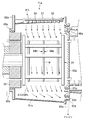
次に洗浄部3bについて説明する。図2に示すように、洗浄部3bには固定された外側チャンバ71aと水平方向にスライド自在な内側チャンバ71bとからなる二重構造を有するチャンバ70が設けられている。図7と図8は洗浄部3bに設けられたチャンバ70にロータ34が挿入されている状態を示す断面図である。ここで図7は内側チャンバ71bを外側チャンバ71aの外側に退避させた退避位置にある状態を、図8は内側チャンバ71bを外側チャンバ71aに収容した処理位置にある状態をそれぞれ示している。
【0055】
外側チャンバ71aは、筒状体61aと、筒状体61aの端面に設けられたリング部材62a・62bと、リング部材62a・62bの内周面に設けられたシール機構63a・63bと、水平方向に多数の洗浄液吐出口54が形成され、筒状体61aに取り付けられた洗浄液吐出ノズル53と、洗浄液吐出ノズル53を収容するノズルケース57と、外側チャンバ71aの下部に設けられ、洗浄液を排出し、また排気をも行うことができる排気/排液管65aを有している。
【0056】
内側チャンバ71bは、筒状体61bと、筒状体61bの端面に設けられたリング部材66a・66bと、リング部材66a・66bの内周面にそれぞれ2箇所ずつ設けられたシール機構67a・67bと、水平方向に多数の洗浄液吐出口56が形成され、筒状体61bに取り付けられた洗浄液吐出ノズル55と、洗浄液吐出ノズル55を収容したノズルケース58と、内側チャンバ71bの下部に設けられ、洗浄液を排出するとともに排気を行うことができる排気/排液管65bを有している。
【0057】
図7および図8に示すように、洗浄部3bには内側チャンバ71bを洗浄、乾燥するクリーニング機構90が設けられている。クリーニング機構90は、筒状体91と、筒状体91の一端面に取り付けられた円盤92aと、筒状体91の別の端面に取り付けられたリング部材92bと、筒状体91に取り付けられたガス吐出ノズル93および排気管94と、を有し、円盤92aには純水吐出ノズル73aと排気管73cが設けられている。なお、後に示す図15および図16に示されるように、洗浄部3bには、内側チャンバ71bのスライド機構120と、クリーニング機構90のスライド機構130が設けられている。
【0058】
まず外側チャンバ71aについてより詳細に説明する。図9はリング部材62b側から見た正面図(但しリング部材62bは図示せず)である。外側チャンバ71aの外形を形成する筒状体61aとリング部材62a・62bは互いに固定されている。外側チャンバ71a全体は筒状体61aを支持するようにして、フレーム99a・99bを用いて所定位置に保持されている。ここでフレーム99a・99bは、外側チャンバ71aの高さ位置と水平位置を微調整する位置調節機構98a・98bを具備しており、ロータ回転機構27の進入・退出がスムーズに所定位置で行えるように調節可能となっている。なお、フレーム99a・99bは、洗浄部3bの外枠を構成する底板97a、天井板97bにそれぞれ固定されている。
【0059】
リング部材62aにはロータ34が進入または退出するためのロータ搬入出口62cが形成されており、このロータ搬入出口62cは図2に示すように蓋体62dによって開閉自在となっている。ロータ搬入出口62cは、ロータ34が外側チャンバ71aに進入した状態では、ロータ回転機構27に設けられた蓋体33により閉塞され、蓋体33の外周面とロータ搬入出口62cとの間隙はシール機構63aによりシールされる。こうしてチャンバ70から搬送部3aへの洗浄液の飛散が防止される。
【0060】
リング部材62aの外側下部には、ロータ回転機構27を搬出する際に蓋体33やシール機構63a等に付着していた洗浄液等がロータ搬入出口62cから液漏れすることを防止するために、液受け62eが設けられている。これにより洗浄部3bの床面の洗浄液による汚れを防止して、洗浄部3bを清浄に保つことができる。
【0061】
図10はシール機構63a・63bの一例を示した説明図である。シール機構63a・63bとしては、例えば、非シール時においては図10(a)に示すように断面略M字型であるが、シール時には図10(b)に示すように所定圧力の空気等を供給することによって中央の凹部が突出して山型となり、この頂点の部分が図示しない蓋体33等に接触することでシール機能が生ずるゴム製チューブ85を用いたものが好適に用いられる。シール機構63a・63bはリング部材62a・62bのそれぞれについて2箇所ずつ形成されており、外側チャンバ71aのシール性をより確かなものとしている。
【0062】
ゴム製チューブ85は、リング部材62a・62bに形成された溝部86に嵌合されている。薬液による劣化や経時劣化によってゴム製チューブ85が使用不能となった場合には、ゴム製チューブ85のみを交換することができる。なお、リング部材62a・62bにゴム製チューブ85が嵌合された別のリング部材を取り付け、ゴム製チューブ85と別のリング部材とを一括して交換する構造としてもよい。このゴム製チューブ85の交換方法については後に詳細に説明する。
【0063】
このようなガス圧を用いたシール機構63a・63bを用いた場合には、ゴム製チューブ85に供給するガス圧を大きくすることによって、外側チャンバ71a内の処理圧力が高い場合であっても良好なシール性を確保することが可能である。このようなシール機構は、後述するシール機構67a・67bについても同様に用いられる。空気圧を用いないゴム製シールリング等を用いることもできるが、この場合にはシール性の強弱を調節することはできないために、洗浄液の漏れ等が生じないように、適宜注意を払うことが好ましい。
【0064】
筒状体61aに設けられた洗浄液吐出ノズル53には、薬液貯蔵ユニット5等の洗浄液供給源から各種薬液や純水、IPAといった洗浄液や窒素(N)ガス等の乾燥ガスが供給されて、洗浄液吐出口54からロータ34に保持されたウエハWに向かってこれらの洗浄液を吐出することができるようになっている。洗浄液吐出ノズル53は、図7と図8では1本のみ示されているが、複数本設けることも可能であり、また、必ずしも筒状体61aの真上に設けなければならないものでもない。このことは洗浄液吐出ノズル55についても同様である。
【0065】
筒状体61aはリング部材62b側の外径がリング部材62a側の外径よりも大きく設定された略円錐状の形状を有している。また、筒状体61aはリング部材62a側よりもリング部材62b側が低く位置するように勾配を設けて配置されている。このために洗浄液吐出ノズル53からウエハWに向けて吐出された各種の洗浄液は、自然に筒状体61aの底面をリング部材62a側からリング部材62b側に流れ、排気/排液管65aを通してドレイン(外部)に排出される。
【0066】
排気/排液管65aからは排気も行うことができるために、洗浄液吐出ノズル53からウエハWに向けて吐出された窒素ガス等の乾燥ガスは、洗浄液吐出ノズル53から排気/排液管65aの向きに流れやすくなっている。
【0067】
図11はこのような乾燥ガスの流れを模式的に示した説明図である。外側チャンバ71aにロータ34を挿入して所定位置に保持した際に、ウエハWの主処理面(鏡面)84aが風下側であるリング部材62b側内側を向き、ウエハWの裏面84bがリング部材62a側を向くようにウエハWがロータ34に保持されていると、気流はウエハWの主処理面84aに衝突し難くなる。これによって、例えば、パーティクル等を含んだ気流が流れてきた場合には、パーティクル等はウエハWの主処理面84aには付着し難いために、主処理面84aへのパーティクル等の付着が低減される。こうしてウエハWの品質を高く維持し、製品への信頼性を高めることが可能となる。
【0068】
また、ウエハWの主処理面84aがリング部材62b側を向き、ウエハWの裏面84bがリング部材62a側を向くようにウエハWがロータ34に保持されていると、外側チャンバ71a内を処理液が流れるときに、この洗浄液が気流の影響等により液跳ねを起こしても、跳ねた洗浄液は洗浄液の流れの向きの影響を受けてウエハWの主処理面84aに衝突し難くなる。これによりウエハWの主処理面84aに液滴が付着して液痕が残るといった問題の発生を抑制することが可能となる。
【0069】
次に、内側チャンバ71bとクリーニング機構90について説明する。内側チャンバ71bを構成する筒状体61bは、外側チャンバ71aの筒状体61aとは異なり、リング部材66a側とリング部材66b側とで同じ外径を有する円筒形状を有しており、水平に設けられている。このために、筒状体61bの下部には洗浄液の外部への排出を容易ならしめるために、筒状体61bから突出し所定の勾配を有する溝部69が形成されている。例えば、内側チャンバ71bが処理位置にあるときに、洗浄液吐出ノズル55からウエハWに向かって吐出された洗浄液は溝部69を流れ、排気/排液管65bを通してドレインから排出される。
【0070】
洗浄液吐出ノズル55には、薬液貯蔵ユニット5等の洗浄液供給源から所定の薬液が供給されて、洗浄液吐出口56からロータ34に保持されたウエハWに向かって吐出することができるようになっている。また、洗浄液吐出ノズル55からは、クリーニング機構90を用いて内側チャンバ71bを洗浄するために、純水および窒素ガス等の乾燥ガスを吐出することができるようになっている。
【0071】
内側チャンバ71bが処理位置にある場合には、図8に示されるように、リング部材66aと蓋体33との間はシール機構67aによってシールされ、またリング部材66bとリング部材62bとの間がシール機構63bによってシールされ、かつ、リング部材66bと円盤92aとの間がシール機構67bによってシールされる。こうして、内側チャンバ71bが処理位置にある場合には、筒状体61b、リング部材66a・66b、円盤92a、蓋体33によって処理室52が形成される。
【0072】
一方、内側チャンバ71bが退避位置にある状態では、リング部材66aとリング部材62bとの間がシール機構63bによってシールされ、かつ、リング部材66aと円盤92aとの間がシール機構67aによってシールされるようになっている。またロータ34が外側チャンバ71a内に挿入されている場合には、蓋体33とリング部材62aとの間がシール機構63aによってシールされている。このために内側チャンバ71bが退避位置にあるときには、図7に示されるように、筒状体61a、リング部材62a・62b、円盤92a、内側チャンバ71bのリング部材66a、ロータ回転機構27の蓋体33から処理室51が形成される。
【0073】
内側チャンバ71bが退避位置にある状態では、上述のように処理位置で処理室51が形成されるとともに、リング部材66aと円盤92aとの間がシール機構67aによってシールされ、リング部材66bとリング部材92bとの間がシール機構67bによってシールされて、筒状体91の外周と筒状体61bの内周との間に狭い略筒状の洗浄処理室72が形成されるようになっている。筒状体91の複数箇所に設けられたガス吐出ノズル93からは洗浄処理室72に向かって窒素ガスや空気等の乾燥ガスを噴射することが可能となっており、こうして、噴射された乾燥ガスは排気管94から排気される。
【0074】
したがって、内側チャンバ71bを処理位置に移動させて、処理室52においてウエハWに所定の薬液を供給した洗浄処理を行った後に、内側チャンバ71bを退避位置に移動させれば、外側チャンバ71aによって形成される処理室51においては引き続き、例えば、純水を用いた洗浄処理を行うことができる。
【0075】
このときに、内側チャンバ71bを用いた洗浄処理に使用した薬液に純水を加えた場合に生成する希釈液が、例えば、強アルカリ性であっても、外側チャンバ71aには薬液が付着していないことから、薬液が付着しているウエハWやロータ34に純水が供給されても、生成する強アルカリ性希釈液の量は少なく、処理室51内に留まる時間も短いことから、ウエハWは強アルカリ性希釈液によるダメージを受け難い。これにより、従来、薬液処理の後に行っていたIPA洗浄工程を省略して、洗浄処理のスループットを向上させ、処理コストを低減することが可能となる。
【0076】
なお、ウエハWの水洗処理が終了した後には引き続いて乾燥処理が行われるが、この乾燥処理が終了した後には、外側チャンバ71aの内部もまた洗浄、乾燥された状態となる。これにより次のバッチのウエハWの洗浄処理において、内側チャンバ71bを用いた薬液処理の後すぐに外側チャンバ71aを用いた水洗処理を行うことができる。
【0077】
このようにウエハWが純水によって洗浄され、また乾燥ガスによって乾燥される際に、円盤35aにおいて円盤92aと対向している面と、円盤35bにおいて蓋体33と対向している面には、純水や乾燥ガスが直接にはあたり難い。このために円盤92aに設けられた純水吐出ノズル73aから円盤35aを洗浄、乾燥するために、また、蓋体33に設けられた純水吐出ノズル73bから円盤35bを洗浄、乾燥するために、それぞれ純水や乾燥ガスが吐出可能となっている。
【0078】
なお、純水吐出ノズル73a・73bを用いて、処理室51・52を所定のガス雰囲気とするために所定のガス、例えば、酸素(O)ガスや二酸化炭素(CO)ガス等を吐出することも可能である。また、処理室51・52に供給されたガスは、排気/排液管65a・65bのみならず、円盤92aに設けられた排気管73cからも排気が可能である。
【0079】
薬液処理が行われた後に退避位置にスライドされた内側チャンバ71bについては、洗浄液吐出ノズル55から洗浄処理室72に純水を吐出することによって自己洗浄を行う。洗浄処理室72は狭く、また、吐出される純水が筒状体91から跳ね返ることから、少量の純水を用いて効果的に内側チャンバ71bの洗浄を行うことができる。洗浄液吐出ノズル55から純水を吐出させることによって、洗浄液吐出ノズル55の内部の洗浄をも同時に行うことができる。なお、筒状体91に純水吐出ノズルを設けることも可能である。
【0080】
こうして洗浄処理室72に吐出された純水が排気/排液管65bから排出された後には、筒状体91に設けられたガス吐出ノズル93から窒素ガスや空気等の乾燥ガスを洗浄処理室72に噴射する。こうして噴射されたガスは排気管94および排気/排液管65bから排気される。このとき洗浄液吐出ノズル55からも乾燥ガスを噴射させることにより、洗浄液吐出ノズル55内の乾燥処理を行うことができる。このようにして、内側チャンバ71bの内部が清浄な状態とされることにより、内側チャンバ71bを次のウエハWの薬液処理に用いることが可能となる。
【0081】
このような内側チャンバ71bの洗浄、乾燥を行う場合には、特にマランゴニ効果を利用することが好ましい。図12はマランゴニ効果を利用した内側チャンバ71bの洗浄処理を行うクリーニング機構90の構成の一形態を示す概略説明図である。図12においては、内側チャンバ71bの筒状体61bとクリーニング機構90の筒状体91は簡略化して示している。
【0082】
図12に示すように、マランゴニ効果を利用して内側チャンバ71bを洗浄する場合には、内側チャンバ71bの上部に排気口144を設ける。また、洗浄液吐出ノズル55へ薬液等を送液する送液管に切替バルブ141a・141bが設けられ、この切替バルブ141a・141bを操作することにより、薬液もしくは純水またはIPA蒸気を含む窒素ガスもしくは窒素ガスを選択して洗浄処理室72へ送ることができるようになっている。IPA蒸気を含む窒素ガスは、例えば、IPAを貯留したタンク143へ窒素ガスをバブリングさせることによって得ることができる。
【0083】
溝部69から廃棄される排液は、切替バルブ142a〜142eを操作することによって、分別回収、廃棄される。例えば、内側チャンバ71bによるウエハWの薬液処理中は、使用された薬液は切替バルブ142aを通して薬液を回収するタンク1に回収される。切替バルブ142bを通してタンク2へ所定の薬液が回収され、切替バルブ142cを通してタンク3へ所定の薬液が回収される構成とすることにより、複数の種類の薬液を使用してウエハWの処理を行う場合の薬液毎の回収が可能となっている。
【0084】
切替バルブ142dは、例えば、30dm/分〜70dm/分で洗浄液を流すことができ、切替バルブ142eは、例えば、5dm/分〜25dm/分で洗浄液を流すことができるようになっている。後述するように切替バルブ142dは内側チャンバ71bの洗浄時に用いられる多量の純水を流す場合等に使用され、切替バルブ142eは洗浄処理室72に貯留した純水を一定流量で排出する際に使用される。
【0085】
図13は、このような構成を有するクリーニング機構90を用いた内側チャンバ71bの洗浄方法の一形態を示すフローチャートであり、図14は図13に示すステップ2〜ステップ5における洗浄処理の形態を模式的に示す説明図である。最初に内側チャンバ71bを用いたウエハWの薬液処理の後に内側チャンバ71bを退避位置へスライドさせて洗浄処理室72を形成する(ステップ1)。洗浄液吐出ノズル55から純水を吐出させて、洗浄処理室72を形成している壁面に付着した薬液を洗い流す(ステップ2)。このステップ2の状態は図14(a)に示されている。また、ステップ2では、排気口144は閉じた状態とされ、薬液を含む純水は切替バルブ142dを通して廃棄される。
【0086】
ドレインから排出される純水に薬液が殆ど含まれないようになったら、切替バルブ142a〜142eを全て閉じた状態とし、かつ、排気口144を開口して、洗浄処理室72内に純水を貯留する(ステップ3)。このステップ3の状態は図14(b)に示されている。このとき排気口144からは洗浄処理室72に純水が貯留される体積に相当するだけのガスが抜ければよい。洗浄処理室72内に貯留する純水の量は、例えば、洗浄液吐出ノズル55が貯留した純水に触れない程度とすることができる。
【0087】
続いて、所定量のIPAを含んだ窒素ガスを洗浄液吐出ノズル55から洗浄処理室72に吐出させながら、洗浄処理室72内が一定の圧力となるように排気口144からの排気を行い、かつ、切替バルブ142eを通じて洗浄処理室72内に貯留された純水を排出する(ステップ4)。このステップ4の状態は図14(c)に示されている。
【0088】
ステップ4では、洗浄処理室72に供給されたIPAが純水の表面近傍に多く溶け込む。そこで、洗浄処理室72内の純水の水面が一定速度で降下するように、切替バルブ142eの開閉量を制御する。これによりIPAの多く溶け込んだ純水が洗浄処理室72を形成する壁面を伝って降下する際に、マランゴニ効果が生じる。このマランゴニ効果により、洗浄処理室72を形成する壁面に純水の液滴が残ることなく均一に乾燥させることができる。
【0089】
洗浄処理室72から純水を排出した後には、排気口144を閉じて切替バルブ142dから排気を行える状態とし、洗浄液吐出ノズル55から窒素ガスのみを吐出させて洗浄処理室72を乾燥させる(ステップ5)。このステップ5の状態は図14(d)に示されている。ステップ5では筒状体91に設けられたガス吐出ノズル93(図7、図8参照)からも窒素ガスを吐出させることも好ましい。なお図14(d)にはガス吐出ノズル93は図示していないが、ガス吐出ノズル93からの窒素ガスの吐出形態を付記している。このような窒素ガスによる乾燥処理は、洗浄処理室72を形成する壁面は適度に湿った状態が保持されて完全には乾燥しないように行う。これによりパーティクルの発生を防止することができる。
【0090】
このような内側チャンバ71bの洗浄処理は、ウエハWの1バッチ処理毎に行うことができる。また、複数バッチ、例えば、5バッチ分のウエハWの処理が終了した後に内側チャンバ71bの洗浄処理を1度行うようにしてもよい。さらに、予め決められた一定時間が経過したときに内側チャンバ71bの洗浄処理を行ってもよい。この場合にはウエハWの処理の進行状況を確認してそのウエハWの処理に支障が生じないようにする。
【0091】
さらにまた、洗浄処理装置1を使用しない時間が一定時間経過した場合、例えば、メンテナンス等のために洗浄処理装置1の稼働を長時間停止した場合には、内側チャンバ71bが完全に乾燥することによってパーティクルが発生していると考えられるために、その後に行う最初の1バッチの処理前に内側チャンバ71bの洗浄処理を行うことも好ましい。これにより内側チャンバ71b内に存在するパーティクル等を除去して清浄な環境でウエハWの処理を行うことができる。
【0092】
次に、洗浄部3bにおける内側チャンバ71bのスライド機構120とクリーニング機構90のスライド機構130について説明する。図15は、内側チャンバ71bを処理位置に移動させ、かつ、クリーニング機構90をメンテナンス位置に移動させた状態を示した平面図であり、図16は、内側チャンバ71bとクリーニング機構90をともにメンテナンス位置に移動させた状態を示す平面図である。
【0093】
なお、クリーニング機構90が内側チャンバ71bの退避位置にある状態は図7および図8に示されており、その位置は、外側チャンバ71aの位置を基準として明確に把握されることから、クリーニング機構90が内側チャンバ71bの退避位置にある状態を示す平面図は示していない。また、図7および図8に示されるように、ウエハWの洗浄処理を行う状態においては、クリーニング機構90は内側チャンバ71bの退避位置にあり、洗浄処理室72を形成することができる位置にある。このために内側チャンバ71bの退避位置がクリーニング機構90にとっての「処理位置」ということができるが、本説明においては、便宜上、クリーニング機構90が内側チャンバ71bの退避位置にあるときはクリーニング機構も退避位置にあるものということとする。
【0094】
クリーニング機構90の構成部材である筒状体91の内部には、円盤92aとリング部材92bとの間に架設されたフレーム95と、フレーム95に取り付けられ、後述するガイド132を貫通させるための空間を形成することができる貫通孔形成部材96a(円盤92a側)・96b(リング部材92b側)が設けられている。また、クリーニング機構90のスライド機構130は、境界壁25に固定して設けられた支柱131と、2本のガイド132と、ガイド132間に架設して設けられたストッパ133a・133bと、ガイド132と支柱131とを連結する連結部材134と、を有している。支柱131と連結部材134とはネジ135等を用いて固定されているために、クリーニング機構90とガイド132および連結部材134とを一体的に支柱131に取り付け、また、支柱131から取り外すことができるようになっている。
【0095】
2本のガイド132は固定されており、2本のガイド132のそれぞれがフレーム95と貫通孔形成部材96a・96bによって形成される空洞を貫通するようにして、クリーニング機構90は配置されている。これによりクリーニング機構90は退避位置とメンテナンス位置との間をスライドできるようになっている。
【0096】
クリーニング機構90を退避位置へ移動させる場合には、貫通孔形成部材96aがストッパ133aに当接することにより筒状体91が位置決めされ、また、図示しないストッパにより筒状体91が移動しないように保持される。
【0097】
クリーニング機構90をメンテナンス位置へ移動させる場合には、貫通孔形成部材96bがストッパ133bに当接することにより筒状体91が位置決めされるようになっている。なお、クリーニング機構90のメンテナンス位置における位置決めは、リング部材92bを連結部材134に当接させることによって行うこともできる。
【0098】
内側チャンバ71bのスライド機構120は、ガイド121と、ガイド121に沿って移動可能な移動体123と、移動体123と内側チャンバ71bのリング部材66bとを連結する連結部材122と、移動体123のスライド範囲を制限するストッパ124とを有し、連結部材122はリング部材66bと脱着可能となっている。洗浄処理時には、ストッパ124が内側チャンバ71bのスライド範囲を処理位置と退避位置との間に制限するが、メンテナンス時にストッパ124を取り外すことによって、内側チャンバ71bをメンテナンス位置にスライドさせることが可能となる。
【0099】
スライド機構120とスライド機構130を用いて、内側チャンバ71bとクリーニング機構90の位置を適宜調節することによって、外側チャンバ71aや内側チャンバ71bを取り外すことなく、シール機構63a・63b・67a・67bにおけるゴム製チューブ85の交換を容易に行うことができる。
【0100】
具体的には、内側チャンバ71bとクリーニング機構90の位置に関係なく、シール機構63aには搬送部3a側からロータ搬入出口62cを通してアクセスできる。また図8または図15に示したように、内側チャンバ71bが処理位置にある場合には、シール機構67aには搬送部3a側からロータ搬入出口62cを通してアクセスすることが可能である。これにより、例えば、シール機構63aとシール機構67aのゴム製チューブ85の交換を容易に行うことができる。
【0101】
また、図15に示すように、内側チャンバ71bを処理位置に保持し、クリーニング機構90をメンテナンス位置に移動させることによって、内側チャンバ71bのシール機構67bにアクセスして、シール機構67bのゴム製チューブ85の交換を行うことができる。さらに図16に示すように、内側チャンバ71bをメンテナンス位置に保持し、クリーニング機構90もまたメンテナンス位置に移動させることによって、外側チャンバ71aのシール機構63bにアクセスして、シール機構63bのゴム製チューブ85の交換を容易に行うことができるようになっている。
【0102】
なお、内側チャンバ71bを処理位置に移動させた状態でクリーニング機構90を取り外した後に、内側チャンバ71bをメンテナンス位置に移動させることによって、内側チャンバ71bも取り外しが容易である。こうして定期的なメンテナンス等において、容易に洗浄部3bの細部にわたる清掃を行うことが可能となる。
【0103】
次に、フープステージ2aに載置されたフープFをフープF1とし、フープステージ2bに載置されたフープFをフープF2として、これら2個のフープF1・F2に収容されたウエハWの洗浄処理を行う場合を例に、その洗浄処理工程について説明する。まず、25枚のウエハWが所定の間隔で平行に収容されたフープF1・F2を、フープF1・F2においてウエハWの出し入れを行うウエハ搬入出口が窓部12a・12bと対面するように、それぞれフープステージ2a・2bに載置する。
【0104】
まずフープF1に収容されたウエハWを搬出するために、窓部12aを開口させてフープF1の内部とウエハ搬送ユニット4の内部が連通した状態とする。その後に、フープF1内のウエハWの枚数および収容状態の検査をウエハ検査機構110を用いて行う。ここでウエハWの収容状態に異常が検出された場合にはフープF1のウエハWについては処理を中断し、例えば、フープF2に収容されたウエハWの搬出を行う。
【0105】
フープF1内におけるウエハWの収容状態に異常が検出されなかった場合には、フープF1に収容された全てのウエハWをウエハ搬送機構16を動作させて搬送用ピック17aに移し替え、続いてリニア駆動機構19および回転機構22を動作させて、搬送用ピック17aがロータ34にアクセスできる状態とする。昇降機構23により搬送用ピック17aの高さ位置を調節し、窓部25aを開口させ、ホルダー開閉機構80を用いてホルダー36bを開き、ウエハWを保持した搬送用ピック17aをロータ34に挿入する。ホルダー36bを閉じた後に搬送用ピック17aを引き戻すことによりウエハWはロータ34に移し替えられる。
【0106】
ホルダー開閉機構80を退避させた後に、ロータ34が外側チャンバ70aに挿入され、また、ロータ搬入出口62cに蓋体33が位置するように、姿勢変換機構28とZ軸リニア駆動機構29とX軸リニア駆動機構30を駆動させてロータ回転機構27を移動させる。そして、シール機構63aを動作させてリング部材62aと蓋体33との間をシールし、さらに内側チャンバ71bを処理位置に移動させて処理室52を形成する。ロータ34をモータ31の駆動によって回転させ、この状態で洗浄液吐出ノズル55から所定の薬液をウエハWに供給して薬液処理を行う。
【0107】
薬液処理の終了後は内側チャンバ71bを退避位置に移動させ、内側チャンバ71bについてはクリーニング機構90による洗浄、乾燥処理を行い、次バッチのウエハWの処理のための準備を行う。一方、外側チャンバ71aによって形成される処理室51にあるウエハWについては、ウエハWを回転させながら、洗浄液吐出ノズル53から純水を吐出して水洗処理を行い、次いで窒素ガスによる乾燥処理を行う。
【0108】
このように洗浄処理ユニット3においてウエハWの処理が行われている間に、ウエハ搬送ユニット4においては、ウエハWを保持していない状態となったウエハ搬送機構16を、搬送用ピック17aがフープステージ2bに載置されたフープF2にアクセスできるように移動させて、フープF1からウエハWを搬出した方法と同様の方法を用いて搬送用ピック17aにフープF2に収容されているウエハWを移し替える。続いてウエハWを保持していない搬送用ピック17bが窓部25aを介してロータ34にアクセスできるように、ウエハ搬送機構16を移動させる。このとき、搬送用ピック17aが未処理のウエハWを保持している。
【0109】
洗浄処理ユニット3においてウエハWの洗浄処理が終了した後に、ウエハWを保持したロータ回転機構27をX軸リニア駆動機構30等を駆動させて、ウエハWを搬送用ピック17a・17bとロータ34との間で受け渡し可能な位置へ移動させる。窓部25aを開口させて、最初に搬送用ピック17bをロータ34にアクセスさせて、ロータ34に保持されたウエハWを搬送用ピック17bに移し替える。続いて搬送用ピック17aがロータ34にアクセスできるように回転機構22を動作させてテーブル21を180°回転させ、搬送用ピック17aに保持された未処理のウエハWをロータ34へ移し替える。
【0110】
ロータ34に保持されたフープF2のウエハWについては、前述したフープF1に収容されていたウエハWの洗浄処理と同様の工程により洗浄処理を施す。その間に、ウエハ搬送機構16については、搬送用ピック17bがフープF1にアクセスできるように移動させ、洗浄処理の終了したウエハWをフープF1に移し替える。その後に、ウエハ搬送機構16を搬送用ピック17bがロータ34にアクセスできる状態としておく。洗浄処理が終了したフープF2のウエハWは、洗浄処理が終了したフープF1のウエハWをフープF1へ戻した手順と同様の手順フープF2に収容される。こうしてフープF1・F2に収容されたウエハWについての洗浄処理が終了する。
【0111】
なお、例えば、フープステージ2cにウエハWが収容されたフープF3がさらに配置されている場合については、フープF1のウエハWの処理が終了した後に、搬送用ピック17aにフープF3に収容されたウエハWを移し替え、洗浄処理が終了したフープF2のウエハWをロータ34から搬出した後に、搬送用ピック17aに保持されたウエハWをロータ34に移し替えることによって、連続してフープF3のウエハWの洗浄処理を行うことができる。
【0112】
以上、本発明の実施の形態について説明してきたが、本発明は上記実施の形態に限定されるものではない。例えば、上記実施の形態では、クリーニング機構90を構成する筒状体91にガス吐出ノズル93を設けた例を示したが、筒状体91には洗浄処理室72に純水を吐出する純水吐出ノズルを設けもよく、また、ガス吐出ノズル93から純水もまた吐出可能な構成とすることも好ましい。また、内側チャンバ71bの乾燥を促進させるために、内側チャンバ71bを構成する筒状体61bにヒータを設けることも好ましい。
【0113】
さらにクリーニング機構90の構成の変更も可能である。図17はクリーニング機構90の別の実施形態であるクリーニング機構90´の概略構造と動作形態を示す説明図である。クリーニング機構90´は、伸縮可能な筒状体(ベローズ)91´と、ベローズ91´を保持するベローズ保持部材151とを有しており、ベローズ保持部材151は内側チャンバ71bのリング部材66bに固定されている。ベローズ保持部材151には純水や窒素ガスを吐出可能な純水吐出ノズル152が設けられており、円盤92aにも純水やガスを吐出する純水吐出ノズル153が設けられている。この純水吐出ノズル153を保持する配管に円盤92を保持する役割を持たせることができる。
【0114】
図17(a)に示されるように、内側チャンバ71bが処理位置にあるときには、ベローズ91´は縮んだ状態となる。一方、図17(b)に示されるように、内側チャンバ71bが退避位置にあるときには、ベローズ91´が延びることで洗浄処理室72´が形成される。この洗浄処理室72´内に純水吐出ノズル152から純水やガスを吐出することにより内側チャンバ71bの洗浄処理を行うことができる。なお、前述したマランゴニ効果を利用して内側チャンバ71bの洗浄処理を行う場合には、洗浄処理室72´の排気を行う排気口はベローズ保持部材151の上部に設ければよい。
【0115】
このようなクリーニング機構90´においては、内側チャンバ71bが処理位置にあるときに、ベローズ91´とベローズ保持部材151との間で形成される空間は密閉されるために、内側チャンバ71bの洗浄処理を行った後にベローズ91´に薬液や純水が付着していた場合にも、これらの洗浄液が外部へ蒸発することを防止することができ、また、ベローズ91´からの液だれを防止することもできる。
【0116】
上記実施の形態においては、本発明を洗浄処理装置に適用した場合について示したが、本発明は、複数の処理液を連続して用いる液処理を行う場合において、ある処理液による液処理に対してその前段階で使用された処理液が混入することが好ましくないために、用いる処理液を変える際にチャンバの洗浄を行っておく必要がある液処理装置全般に用いることが可能である。例えば、本発明の液処理装置は、所定の塗布液を塗布する塗布処理やエッチング処理等に適用することも可能である。
【0117】
また、チャンバ70として二重構造を有する場合を例に説明したが、チャンバは1個でもよく、また、三重構造であってもよい。1個のチャンバを用いる場合には、薬液処理後にチャンバを洗浄している際には基板に対しては続いて液処理を行うことができない場合が多くなり、スループットの向上という効果は得られ難いが、前段で使用された薬液と後段で使用される薬液との混合を防止するために、これらの薬液処理の中間において前段の薬液を洗い流すために用いられていた処理液を使用する必要がなくなるために、処理コストを低減させる効果を得ることが可能となる。さらに、基板としては半導体ウエハを例に挙げたが、これに限らず、液晶表示装置(LCD)用基板等、他の基板の処理にも適用することができる。
【0118】
【発明の効果】
上述の通り、本発明の液処理装置にはチャンバのクリーニング機構が設けられているために、複数の処理液を連続して用いる液処理を行う場合において、ある処理液に対してその前段階で使用された処理液が混入することが好ましくないときには、処理液を変える前にチャンバの洗浄を行うことが可能である。これにより処理液のコンタミネーションの発生が防止され、処理液の特性を引き出して精度の高い液処理を行うことが可能となり、ひいては基板の品質を高く保持することが可能となるという効果が得られる。また、例えば、所定の薬液を用いた液処理の後に、その処理液を除去するための予備的な処理液を供給する必要があった場合には、チャンバを洗浄することができるために、予備的な処理液による処理工程を省略して、次の所定の処理液による液処理を行うことが可能となる。これにより予備的な処理液に要する費用を削減し、また処理時間を短縮することも可能となり、処理コストが低減されるという効果が得られる。特に、二重構造のチャンバを用いた場合には、一方のチャンバを用いて液処理を行った後に時間を空けることなく別のチャンバを用いて液処理を行うことができ、これによってスループットを向上させることができるために、処理コストの低減の効果をより大きく得ることが可能となる。
【図面の簡単な説明】
【図1】 本発明の一実施形態である洗浄処理装置を示す斜視図。
【図2】 図1に示した洗浄処理装置の平面図。
【図3】 図1に示した洗浄処理装置の側面図。
【図4】 図1に示した洗浄処理装置の別の側面図。
【図5】 ロータの構造を示す説明図。
【図6】 ロータ回転機構の移動形態を示す説明図。
【図7】 ロータをチャンバに挿入した状態の一形態を示す断面図。
【図8】 ロータをチャンバに挿入した状態の別の形態を示す断面図。
【図9】 外側チャンバの保持状態を示す正面図。
【図10】 シール機構の非シール時とシール時の状態を示す説明図。
【図11】 外側チャンバ内での気流の状態を示す説明図。
【図12】 クリーニング機構の構成の一形態を示す説明図。
【図13】 内側チャンバの洗浄方法の一形態を示すフローチャート。
【図14】 内側チャンバの洗浄形態を模式的に示す説明図。
【図15】 洗浄部におけるチャンバとクリーニング機構の位置関係の一形態を示す平面図。
【図16】 洗浄部におけるチャンバとクリーニング機構の位置関係の別の形態を示す平面図。
【図17】 クリーニング機構の構成の別の形態を示す説明図。
【符号の説明】
1;洗浄処理装置
2;フープ搬入出部
3;洗浄処理ユニット
4;ウエハ搬送ユニット
5;薬液貯蔵ユニット
6;電源ボックス
16;ウエハ搬送機構
27;ロータ回転機構
34;ロータ
63a・63b;シール機構
67a・67b;シール機構
71a;外側チャンバ
71b;内側チャンバ
90;クリーニング機構
91;筒状体
92a;円盤
92b;リング部材
93;ガス吐出ノズル
94;排気管
120;スライド機構(内側チャンバ用)
130;スライド機構(クリーニング機構用)
F;フープ
W;半導体ウエハ(基板)
[0001]
BACKGROUND OF THE INVENTION
  The present invention relates to a liquid processing apparatus and a liquid processing method for performing liquid processing and drying processing on various substrates such as semiconductor wafers and LCD substrates.
[0002]
[Prior art]
  For example, in a semiconductor device manufacturing process, a semiconductor wafer as a substrate is washed with a predetermined chemical solution or pure water to contaminate particles, organic contaminants, metal impurities, etc. from the wafer, polymer after etching, etc. Wafer cleaning device to remove nitrogen and nitrogen (N2) Wafer drying apparatuses are used that dry a wafer by removing droplets from the wafer with an inert gas such as a gas or IPA vapor having high volatility and hydrophilicity.
[0003]
  As such a cleaning / drying apparatus, one that batch-processes a plurality of wafers is known. For example, a container in which a plurality of wafers are accommodated so that their main surfaces are substantially parallel to each other is known. A wafer placed on a predetermined position of a cleaning / drying device, and simultaneously taking out a plurality of wafers contained in the container using a transport mechanism, and transferring the wafers to a rotor that holds the wafers. After performing predetermined liquid processing and drying processing, the wafer is transferred to the container again using the transfer mechanism.
[0004]
  Here, with respect to the process from washing to drying, after the chemical treatment using the chemical solution, the chemical solution is washed away using IPA, and then the water washing treatment using pure water is performed. Finally, the IPA vapor or N2A processing step of performing a gas drying process is generally used.
[0005]
[Problems to be solved by the invention]
  However, in recent years, in such a series of processing steps, the processing step of washing away the chemical solution by IPA is omitted, the processing step is shortened, and the processing cost is reduced by not using IPA. There is a growing demand for reduction. However, since the chemical solution adheres to the inner wall of the chamber after the chemical treatment and the chemical solution is not completely discharged at the bottom of the chamber, a certain amount of the chemical solution remains. When the water washing treatment is performed after the treatment, for example, a strong alkaline aqueous solution is generated by diluting the chemical solution with pure water. If this strong alkaline aqueous solution exists in the chamber for a long time, the wafer may be damaged.
[0006]
  In general, a chamber forming a processing space for performing liquid processing has a seal structure so that the processing liquid does not scatter to the outside during the liquid processing, and a seal material such as rubber is used for the seal portion. It is common. Such a sealing material needs to be replaced suddenly or periodically due to deterioration due to chemicals or the like, or deterioration over time. However, in a conventional liquid processing apparatus, the chamber itself is used to replace the sealing material. Workability and maintainability were not always good, such as having to be removed.
[0007]
  Furthermore, during chemical processing and drying processing, it is required to maintain high substrate quality and improve reliability by making the amount of particles adhering to the main surface of the substrate small and preventing traces of chemical droplets from remaining. However, it is still not enough.
[0008]
  The present invention has been made in view of such circumstances, and an object of the present invention is to provide a liquid processing apparatus and a liquid processing method that prevent the substrate from being damaged by mixing the processing liquid. It is another object of the present invention to provide a liquid processing apparatus that can perform liquid processing without using a processing liquid that has been used intermediately to prevent mixing of different processing liquids.
[0009]
[Means for Solving the Problems]
  In order to solve the above problems, the first aspect of the present invention.1'sAccording to an aspect, a liquid processing apparatus that performs liquid processing by supplying a processing liquid to a plurality of substrates, the rotor capable of holding the plurality of substrates at a predetermined interval;A processing chamber is provided that is slidable between a processing position for processing the plurality of substrates and a retracted position that is different from the processing position, and that accommodates the rotor at the processing position.A chamber;Processing roomA treatment liquid discharge nozzle for discharging the treatment liquid onto a substrate accommodated in the substrate, and a cleaning mechanism for cleaning the chamber.When the chamber is in the retracted position,Provided to form a cleaning treatment chamber with the chamberWashingA processing chamber forming member, a cleaning liquid discharge nozzle for discharging a cleaning liquid into the cleaning processing chamber, a gas discharge nozzle for discharging a drying gas into the cleaning processing chamber,
  There is provided a liquid processing apparatus characterized by comprising:
[0010]
  According to the second aspect of the present invention, a substantially cylindrical outer chamber provided in a fixed manner, and an inside of the outer chamber.is thereProcessing position andOutside the outer chamberA substantially cylindrical inner chamber slidably provided between the retracted position;A cleaning processing chamber forming member provided to form a cleaning processing chamber with the inner chamber when the inner chamber is in the retracted position;Using a liquid processing apparatus having a cleaning mechanism for cleaning the inner chamber at the retracted position, the processing liquid is supplied to the substrate held by a rotor capable of holding a plurality of substrates at predetermined intervals to perform liquid processing. A liquid processing method for performing a liquid processing on the substrate using the inner chamber at the processing position, and liquid processing on the substrate using the outer chamber after the inner chamber is retracted. There is provided a liquid processing method comprising: a second step to be performed; and a third step of performing a cleaning process of the inner chamber by the cleaning mechanism at a predetermined timing at the retracted position.
[0011]
  According to such a liquid processing apparatus and a liquid processing method, since a chamber cleaning mechanism is provided, when performing liquid processing using a plurality of processing liquids continuously, a certain processing liquid is preceded by the preceding stage. When it is not preferable to mix the processing liquid used in the above, the chamber can be cleaned before the liquid processing is performed by changing the processing liquid. As a result, the occurrence of contamination of the processing liquid is prevented, the characteristics of the processing liquid can be extracted, and high-precision liquid processing can be performed, and as a result, the quality of the substrate can be kept high.
[0012]
  When a chamber having a double structure consisting of an inner chamber and an outer chamber is used as a chamber, after performing liquid treatment with a treatment liquid using one chamber, another treatment is performed using the other chamber. Liquid treatment with liquid can be performed. As a result, mixing of the treatment liquid can be prevented, and the throughput can be improved. However, in this case, after a series of processing is completed for one batch of substrates, the first used chamber must be returned to a clean state before starting the liquid processing for the next batch of substrates. A new problem arises. Since the liquid processing apparatus of the present invention has a cleaning mechanism, it is possible to solve a new problem caused by using a chamber having such a double structure. In addition, it is effective in reducing processing costs.
[0013]
DETAILED DESCRIPTION OF THE INVENTION
  Hereinafter, embodiments of the present invention will be specifically described with reference to the accompanying drawings. The liquid processing apparatus according to one embodiment of the present invention can be applied to, for example, a cleaning processing apparatus or a drying processing apparatus using various substrates as objects to be processed. In this embodiment, the semiconductor wafer (wafer) is transported and cleaned. A cleaning processing apparatus configured to perform drying in a batch manner will be described as an example.
[0014]
  FIG. 1 is a perspective view showing an appearance of the cleaning processing apparatus 1. As shown in FIG. 1, the cleaning processing apparatus 1 includes a FOUP loading / unloading section provided with FOUP stages 2 a to 2 c for mounting a FOUP (Front Opening Unified Pod) F capable of accommodating a plurality of wafers W. 2, a cleaning processing unit 3 that performs a cleaning process on the wafer W, a wafer transfer unit 4 that is provided between the FOUP loading / unloading unit 2 and the cleaning processing unit 3, and that transfers the wafer W, and a cleaning process It is mainly comprised from the chemical | medical solution storage unit 5 which stores the chemical | medical solution for.
[0015]
  Further, a power supply box 6 for various electric drive mechanisms and electronic control devices provided in the cleaning processing apparatus 1 and a temperature control box 7 for controlling the temperature of each unit constituting the cleaning processing apparatus 1 are cleaned. Provided above the unit 3, and above the wafer transfer unit 4 are a display box 9 for controlling various display panels provided in the cleaning processing apparatus 1 and a wafer transfer mechanism provided in the wafer transfer unit 4. A transport mechanism control box 10 in which 16 control devices are accommodated is provided. Further, a hot exhaust box 8 for collecting and exhausting hot exhaust from each box is provided above the chemical solution storage unit 5.
[0016]
  FIG. 2 is a schematic plan view of the cleaning processing apparatus 1, FIG. 3 is a schematic side view of the cleaning processing apparatus 1, and FIG. 4 is a schematic diagram illustrating a state in which some drive mechanisms are driven in the schematic side view of FIG. Each side view is shown. Here, in FIGS. 2 to 4, only the hoop carry-in / out unit 2, the cleaning processing unit 3, the wafer transfer unit 4, and the chemical solution storage unit 5 are shown, and the upper portion of the cleaning processing unit 3, the wafer transfer unit 4, and the chemical solution storage unit 5. The power supply box 6 and other various box portions provided in FIG. As will be described later, the cleaning processing unit 3 is divided into a transport unit 3a and a cleaning unit 3b. FIGS. 3 and 4 show a schematic structure of the transport unit 3a.
[0017]
  The FOUP F mounted on the FOUP stages 2a to 2c can accommodate a plurality of wafers W, for example, 25 wafers at a predetermined interval so that the main surface is horizontal, and one side surface of the FOUP F. Is provided with a wafer loading / unloading port for loading and unloading the wafer W. The FOUP F has a lid 11 that opens and closes the wafer loading / unloading port. The lid 11 can be attached to and detached from the FOUP F by lid opening / closing mechanisms 15a to 15c described later.
[0018]
  Window portions 12a to 12c are provided in the boundary wall 12 between the wafer transfer unit 4 and the hoop loading / unloading portion 2, and the outer peripheral portion of the wafer loading / unloading port formed in the hoop F closes the window portions 12a to 12c. In addition, the hoop F is placed on the hoop stages 2a to 2c so that the lid 11 can be detached by the lid opening / closing mechanisms 15a to 15c (see FIG. 4).
[0019]
  On the inner side of the boundary wall 12 (on the wafer transfer unit 4 side), shutters 13a to 13c for opening and closing the windows 12a to 12c and lifting mechanisms 14a to 14c for raising and lowering the shutters 13a to 13c are positioned at the positions of the windows 12a to 12c. Lid opening / closing mechanisms 15a to 15c made of 14c are provided. The lid opening / closing mechanisms 15a to 15c have a lid gripping means such as a suction pad (not shown) so that the lid 11 of the hoop F can be lifted and lowered together with the shutters 13a to 13c.
[0020]
  When the FOUP F is not placed on the FOUP stages 2a to 2c, the shutters 13a to 13c are in a state of closing the windows 12a to 12c, so that intrusion of particles and the like from the outside to the wafer transfer unit 4 is prevented. . On the other hand, when the wafer W is unloaded from the FOUP F or loaded into the FOUP F, the shutters 13a to 13c and the FOUP F so that transfer picks 17a and 17b of the wafer transfer mechanism 16 described later can access the FOUP F. The lid body 11 is lowered by the lid body opening / closing mechanisms 15a to 15c, and the windows 12a to 12c are opened.
[0021]
  The wafer transfer unit 4 is provided with a wafer inspection mechanism 110 for measuring the number of wafers W in the FOUP F adjacent to the lid opening / closing mechanisms 15a to 15c. The wafer inspection mechanism 110 includes, for example, a reflective optical sensor 111 having a transmitter and a receiver using an infrared laser. The reflected light from the end surface of the wafer W is received while oscillating an infrared laser toward the wafer W while scanning the reflective sensor 111 in the Z direction (vertical direction) along the guide 112 using the motor 113. Thereby, the number of wafers W accommodated in the FOUP F and the accommodation state, for example, whether the wafers W are accommodated one by one in a substantially parallel manner at a predetermined pitch, whether the two wafers W are not accommodated in an overlapping manner. It is possible to inspect whether or not the wafer W is not accommodated obliquely with a step difference, whether or not the wafer W has jumped out of a predetermined position in the FOUP F, and the like.
[0022]
  If the wafer inspection mechanism 110 is attached to the wafer transfer mechanism 16 so that the wafer inspection mechanism 110 can be moved together with the wafer transfer mechanism 16, the wafer inspection mechanism 110 may be provided only at one location. Further, for example, a sensor for confirming the number of wafers W accommodated and a sensor for inspecting the accommodation state of the wafers W may be provided separately. Further, the wafer inspection mechanism 110 may be attached to the lid opening / closing mechanisms 15a to 15c.
[0023]
  The wafer transfer unit 4 is provided with a filter fan unit (FFU) 24a for blowing clean air into the wafer transfer unit 4 at the ceiling. A part of the downflow from the FFU 24a flows out of the window portions 12a to 12c and flows into the FOUP F placed on the FOUP stages 2a to 2c in a state where the window portions 12a to 12c are opened. As a result, clean air is supplied to the wafer W in the FOUP F, thereby preventing particles from adhering to the wafer W. Note that an ionizer (not shown) may be provided below the FFU 24a so that the wafer W can be neutralized.
[0024]
  The wafer transfer unit 4 is provided with a wafer transfer mechanism 16. The wafer transfer mechanism 16 includes a linear drive mechanism 19 having a guide extending in the X direction, transfer picks 17a and 17b for holding the wafer W, and holding units 18a and 17b for holding the transfer picks 17a and 17b, respectively. 18b, slide mechanisms 20a and 20b to which transfer picks 17a and 17b and holding portions 18a and 18b are respectively attached, a rotatable table 21 to which slide mechanisms 20a and 20b are attached, and a rotation mechanism for rotating the table 21 22 and a lifting mechanism 23 that lifts and lowers the upper part from the rotating mechanism 22.
[0025]
  By providing two types of transfer picks 17a and 17b in the wafer transfer mechanism 16, for example, the transfer pick 17a is used for transferring an unprocessed wafer W, and the transfer pick 17b is used for cleaning a wafer W that has been cleaned. Can be used to transport. In this case, for example, compared with a case where only one transfer arm is provided, particles or the like adhering to the unprocessed wafer W adhere to the transfer arm and further adhere to the processed wafer W. The situation where it does is prevented effectively. Also, by providing two transfer arms, the next unprocessed wafer W can be delivered immediately after receiving the processed wafer W with the cleaning processing unit 3.
[0026]
  One transfer pick 17a transfers one wafer W. Twenty-five transfer picks 17a are held by the holding portion 18a substantially at a predetermined interval so that 25 wafers W accommodated in the FOUP F can be transferred at a time. Similarly, the 25 conveyance picks 17b are also held by the holding portion 18b at a predetermined interval substantially in parallel.
[0027]
  When the wafer W is transferred between the FOUP F or the rotor 34 described later and the transfer picks 17a and 17b, the transfer picks 17a and 17b must be moved up and down by a predetermined distance. The raising / lowering operation of 17b can be performed from the raising / lowering mechanism 23. In addition, you may provide the raising / lowering mechanism which raises / lowers the picks 17a * 17b for conveyance separately in holding | maintenance part 18a * 18b.
[0028]
  The transport picks 17a and 17b are slidable in the length direction of the transport picks 17a and 17b by the slide mechanisms 20a and 20b together with the holding portions 18a and 18b. The table 21 is configured to be rotatable (horizontal direction θ shown in FIG. 2) in a horizontal plane by a rotation mechanism 22. Further, the heights of the transport picks 17a and 17b can be adjusted by the elevating mechanism 23, and the transport picks 17a and 17b can be moved in the X direction by the linear drive mechanism 19 together with the elevating mechanism 23 and the like. As a result, the transfer picks 17a and 17b can access any of the hoops F and the rotors 34 placed on the hoop stages 2a to 2c, and thus the hoops F and the rotors 34 placed on the hoop stages 2a to 2c are connected to each other. The wafer W can be transferred in a horizontal state.
[0029]
  For example, when the transfer pick 17a is used to transfer an unprocessed wafer W and is transferred from the FOUP F placed on the FOUP stage 2b to the rotor 34 provided in the cleaning processing unit 3, first, The linear drive mechanism 19 is driven to move the transport pick 17a in the X direction so that the transport pick 17a can access the hoop F placed on the hoop stage 2b. Next, after the elevation mechanism 23 is driven to adjust the height of the transport pick 17a, the slide mechanism 20a is operated to slide the transport pick 17a and the holding portion 18a toward the hoop stage 2b. The wafer W is unloaded from the FOUP F by holding the wafer W on the transfer pick 17a and returning the transfer pick 17a and the holding portion 18a to their original positions.
[0030]
  Subsequently, while the rotation mechanism 22 is operated to rotate the table 21 by 180 °, the linear drive mechanism 19 is driven so that the transfer pick 17a can access the rotor 34. When the transfer pick 17a and the holding portion 18a are slid to the rotor 34 side, the wafer W is transferred to the rotor 34 (see FIG. 4), and the transfer pick 17a and the holding portion 18a are returned to their original positions again. The conveyance to 34 is completed.
[0031]
  In this wafer transfer mechanism 16, since the transfer picks 17a and 17b are provided at point-symmetrical positions with respect to the rotation center of the table 21, the table 21 is moved in a state where the slide mechanisms 20a and 20b are not extended. When rotated, even if the transfer picks 17a and 17b hold the wafer W, the range of the locus through which the transfer picks 17a and 17b pass can be narrowed. Thus, in the cleaning processing apparatus 1, the wafer transfer unit 4 is saved in space.
[0032]
  A window 25a for transferring the wafer W is formed on the boundary wall 25 that partitions the wafer transfer unit 4 and the cleaning processing unit 3, and the window 25a can be moved up and down by an elevating mechanism 26b. It is opened and closed by 26a. The shutter 26a is provided on the wafer transfer unit 4 side, but may be provided on the cleaning processing unit 3 side. The wafer W is transferred between the wafer transfer unit 4 and the cleaning processing unit 3 through the window 25a.
[0033]
  In addition, since the atmosphere of the wafer transfer unit 4 and the cleaning processing unit 3 can be separated by the shutter 26a, for example, even when the cleaning liquid is scattered in the cleaning processing unit 3 or the vapor of the cleaning liquid is diffused, The contamination is prevented from spreading to the wafer transfer unit 4.
[0034]
  The cleaning processing unit 3 includes a transport unit 3a and a cleaning unit 3b. A filter fan unit (FFU) 24b is provided on the ceiling portion of the transport unit 3a, and clean air from which particles are removed is blown into the transport unit 3a. Note that an ionizer (not shown) may be provided at the lower part of the FFU 24b to remove the charge from the wafer W.
[0035]
  The transport unit 3 a includes a rotor rotation mechanism 27, a posture conversion mechanism 28 that controls the posture of the rotor rotation mechanism 27, a Z-axis linear drive mechanism 29 that moves the rotor rotation mechanism 27 and the posture conversion mechanism 28 in the vertical direction, The X-axis linear drive mechanism 30 that moves the Z-axis linear drive mechanism 29 in the horizontal direction, the particles generated from the attitude conversion mechanism 28 and the Z-axis linear drive mechanism 29 scatter to the rotor rotation mechanism 27 side, adhere to the wafer W, etc. And a cover 46 for preventing particles generated from the X-axis linear drive mechanism 30 from scattering to the rotor rotating mechanism 27 and adhering to the wafer W. .
[0036]
  The rotor rotation mechanism 27 includes a rotor 34 that can hold the wafers W at predetermined intervals, a motor (rotation mechanism) 31 that rotates the rotor 34 so that the wafers W held by the rotor 34 rotate in-plane, and an attitude conversion mechanism. 28, a lid 33 that closes the rotor loading / unloading port 62c formed in the outer chamber 71a when the rotor 34 is inserted into an outer chamber 71a described later, and the coupling portion 32 and the lid 33 are passed through. The rotating shaft 50 (see FIGS. 5, 7, and 8 shown later) connecting the rotor 34 and the motor 31.
[0037]
  FIG. 5 is a perspective view showing a schematic structure of the rotor 34. The rotor 34 includes a pair of disks 35a and 35b arranged at a predetermined interval, a locking member 36a in which a groove for holding the wafer W is formed, and a groove or the like similar to the locking member 36a. A holder 36b that is formed and can be opened and closed, and a lock pin 36c that controls whether the holder 36b can be opened and closed.
[0038]
  A holder opening / closing mechanism 80 for opening and closing the holder 36b is provided on the boundary wall 25 (see FIGS. 3 and 4). The holder opening / closing mechanism 80 includes a lock pin pressing cylinder 81 and a holder opening / closing cylinder 82. is doing. Since the cover 40 is provided in the boundary wall 25 where the holder opening / closing mechanism 80 is provided, the wafer transfer unit 4 and the cleaning processing unit 3 are separated from each other.
[0039]
  The disk 35b is fixed to the rotating shaft 50 using, for example, a screw 35c, and the locking member 36a can be fixed between the disks 35a and 35b by screwing or the like from the outside of the disks 35a and 35b. For example, the lock pin 36c protrudes outward in a normal state, and the holder 36b cannot be opened and closed in this state. On the other hand, when the holder opening / closing mechanism 80 accesses the rotor 34 and the lock pin 36c is pushed inward by the pressing force from the lock pin pressing cylinder 81, the holder 36b opens / closes the holder. The cylinder 82 can be opened and closed freely.
[0040]
  When the holder 36b is opened, the wafer W can be transferred between the rotor 34 and the transfer picks 17a and 17b. On the other hand, when the holder 36b is closed, the wafer W in the rotor 34 can be transferred. The rotor 34 is held in a state where it does not jump out.
[0041]
  The holder opening / closing mechanism 80 allows the lock pin pressing cylinder 81 and the holder opening / closing cylinder 82 to access the lock pin 36c and the holder 36b, respectively, at a position where the wafer W is transferred between the rotor 34 and the transfer picks 17a and 17b. Thus, it is freely rotatable between the retracted position shown in FIG. 3 and the processing position shown in FIG. The lock pin pressing cylinder 81 has a pressing mechanism capable of pressing the lock pin 36c into the rotor 34 at the processing position so that the above-described opening / closing operation of the holder 36b can be performed. It is operable to access the holder 36b outside the disk 35a to open and close the holder 36b.
[0042]
  When the holder 36b is opened / closed according to the operation mode of the holder 36b, the lock pin 36c, and the holder opening / closing mechanism 80 described above, for example, the holder opening / closing mechanism 80 in the retracted position is first moved to the processing position to access the rotor 34. The lock pin pressing cylinder 81 holds the lock pin 36c in a state of being pushed into the rotor 34. In this state, the holder opening / closing cylinder 82 is operated to open the holder 36b. As a result, the wafer W can be loaded and unloaded.
[0043]
  When the loading / unloading operation of the wafer W is completed, the pressing force of the lock pin pressing cylinder 81 is released after the holder 36b is closed, and the lock pin 36c protrudes from the disk 35a, that is, the holder 36b is locked. The holder opening / closing mechanism 80 is returned to the retracted position.
[0044]
  The attitude converting mechanism 28 that controls the attitude of the rotor rotating mechanism 27 includes a rotating mechanism 42 and a rotating shaft 41 attached to the rotating mechanism 42, and the rotating shaft 41 is fixed to the connecting portion 32 of the rotor rotating mechanism 27. Has been. The entire rotor rotation mechanism 27 can be held by the rotation mechanism 42 in a posture (vertical posture) such that the wafer W is held in a horizontal state as shown in FIG. 3 or FIG. Thus, the wafer W can be converted and held in a posture (horizontal posture) in which the wafer W is held in a vertical state.
[0045]
  The Z-axis linear drive mechanism 29 includes a motor 43, a power transmission unit 44 that transmits the rotational driving force of the motor 43 to the attitude conversion mechanism 28, a guide 47, and a support body 48 that supports the guide 47. . The posture conversion mechanism 28 is fitted with the guide 47 so that it can move along the guide 47. When the motor 43 is rotated, this rotational driving force is transmitted to the posture conversion mechanism 28 via the power transmission unit 44, and the posture conversion mechanism 28 is moved. The conversion mechanism 28 can move along the guide 47 together with the rotor rotation mechanism 27 in the Z direction (vertical direction) by a predetermined distance.
[0046]
  In addition, although the mechanism which converts the rotational displacement of the motor 43 into a linear displacement was shown as the Z-axis linear drive mechanism 29, it is not limited to such a mechanism, for example, instead of the motor 43, an air cylinder or the like directly Alternatively, a drive mechanism that generates a linear displacement may be used.
[0047]
  The X-axis linear drive mechanism 30 includes a guide 49, a motor (not shown), a ball screw 39a coupled to the motor, a meshing member 39b meshed with the ball screw 39a, and a meshing member 39b fitted to the guide 49. And a connecting member 38 that connects the support 48.
[0048]
  The ball screw 39a operates by rotating the motor, and the meshing member 39b moves in the X direction according to the operation of the ball screw 39a. At this time, since the connecting member 38 connects the engagement member 39b and the support body 48, the connection member 38 and the support body 48 also move in the X direction together with the engagement member 39b. That is, when the meshing member 39b moves in the X direction, the rotor rotating mechanism 27, the attitude converting mechanism 28, and the Z-axis linear drive mechanism 29 are simultaneously moved in the X direction.
[0049]
  FIG. 6 is an explanatory diagram showing an example of a mode in which the rotor rotation mechanism 27 is moved using the attitude conversion mechanism 28, the Z-axis linear drive mechanism 29, and the X-axis linear drive mechanism 30. FIG. 6A shows the movement trajectory of the connecting portion 32 in the rotor rotating mechanism 27. FIGS. 6B to 6E show the positions P1 to P1 at which the connecting portion 32 is shown in FIG. The state (attitude) of the rotor rotation mechanism 27 when it is in P4 is shown. Hereinafter, an example will be described in which the rotor rotating mechanism 27 is moved so that the connecting portion 32 moves from the position P1 to the position P4 in order to insert the rotor 34 holding the wafer W into the chamber 70.
[0050]
  When the connecting portion 32 is at the position P1, the rotor rotating mechanism 27 is in a position where the wafer W can be transferred between the rotor 34 and the wafer transfer mechanism 16, and at this time, the rotor rotating mechanism 27 is in the vertical posture. It is in the state of. In a state where the wafer W is accommodated in the rotor 34, first, the Z-axis linear drive mechanism 29 is operated to raise the rotor rotating mechanism 27 and the posture changing mechanism 28 so that the connecting portion 32 moves to the position P2. At the position P2, the attitude changing mechanism 28 is operated to rotate the entire rotor rotating mechanism 27 by 90 ° so that the wafer W is changed from the horizontal holding state to the vertical holding state. To do.
[0051]
  Next, the Z-axis linear drive mechanism 29 is operated again, and the entire rotor rotation mechanism 27 remains in the horizontal posture so that the connecting portion 32 is moved to the position P3. When the posture of the rotor rotation mechanism 27 is changed at the intermediate point when the rotor rotation mechanism 27 is raised at the position P2, the rotor rotation mechanism 27 is rotated when the connecting portion 32 is at the position P1 or the position P3. Compared to the above, it is sufficient that the space required for the rotation of the rotor rotation mechanism 27 is narrow. This makes it possible to reduce the occupied volume of the transport unit 3a.
[0052]
  When the connecting portion 32 reaches the position P3, the X-axis linear drive mechanism 30 is then operated to move the position of the connecting portion 32 horizontally to the position P4. When the connecting portion 32 is at the position P4, the rotor 34 is inserted into the chamber 70 so that the cleaning process can be performed. In this way, the rotor 34 can be moved from the transfer position to the wafer transfer mechanism 16 to the cleaning processing position.
[0053]
  The state in which the connecting portion 32 is at the position P4 and the rotor 34 is inserted into the chamber 70 is shown in detail in FIGS. In addition, after the cleaning process of the wafer W is completed, the moving path of the rotor rotation mechanism 27 described above is reversed so that the connecting portion 32 moves from the position P4 to the position P1, thereby the wafer W in the rotor 34 is moved. Needless to say, the wafer can be moved to a position where it can be transferred to the wafer transfer mechanism 16.
[0054]
  Next, the cleaning unit 3b will be described. As shown in FIG. 2, the cleaning unit 3b is provided with a chamber 70 having a double structure including a fixed outer chamber 71a and an inner chamber 71b slidable in the horizontal direction. 7 and 8 are sectional views showing a state in which the rotor 34 is inserted into the chamber 70 provided in the cleaning unit 3b. Here, FIG. 7 shows a state where the inner chamber 71b is retracted to the outside of the outer chamber 71a, and FIG. 8 shows a state where the inner chamber 71b is in the processing position where the inner chamber 71b is accommodated in the outer chamber 71a.
[0055]
  The outer chamber 71a includes a cylindrical body 61a, ring members 62a and 62b provided on an end surface of the cylindrical body 61a, seal mechanisms 63a and 63b provided on inner peripheral surfaces of the ring members 62a and 62b, and a horizontal direction. A large number of cleaning liquid discharge ports 54 are formed on the cylindrical body 61a, a cleaning liquid discharge nozzle 53 attached to the cylindrical body 61a, a nozzle case 57 for housing the cleaning liquid discharge nozzle 53, and a lower portion of the outer chamber 71a for discharging the cleaning liquid. In addition, an exhaust / drainage pipe 65a capable of exhausting is also provided.
[0056]
  The inner chamber 71b includes a cylindrical body 61b, ring members 66a and 66b provided on the end surface of the cylindrical body 61b, and seal mechanisms 67a and 67b provided at two locations on the inner peripheral surface of the ring members 66a and 66b. A large number of cleaning liquid discharge ports 56 are formed in the horizontal direction, provided at the lower part of the inner chamber 71b, a cleaning liquid discharge nozzle 55 attached to the cylindrical body 61b, a nozzle case 58 containing the cleaning liquid discharge nozzle 55, It has an exhaust / drainage pipe 65b that can exhaust the cleaning liquid and exhaust it.
[0057]
  As shown in FIGS. 7 and 8, the cleaning unit 3b is provided with a cleaning mechanism 90 for cleaning and drying the inner chamber 71b. The cleaning mechanism 90 is attached to the tubular body 91, a disk 92 a attached to one end face of the tubular body 91, a ring member 92 b attached to another end face of the tubular body 91, and the tubular body 91. The gas discharge nozzle 93 and the exhaust pipe 94 are provided, and the disk 92a is provided with a pure water discharge nozzle 73a and an exhaust pipe 73c. 15 and 16, which will be described later, the cleaning unit 3b is provided with a slide mechanism 120 of the inner chamber 71b and a slide mechanism 130 of the cleaning mechanism 90.
[0058]
  First, the outer chamber 71a will be described in more detail. FIG. 9 is a front view as seen from the ring member 62b side (however, the ring member 62b is not shown). The cylindrical body 61a and the ring members 62a and 62b that form the outer shape of the outer chamber 71a are fixed to each other. The entire outer chamber 71a is held at a predetermined position using frames 99a and 99b so as to support the cylindrical body 61a. Here, the frames 99a and 99b are provided with position adjusting mechanisms 98a and 98b for finely adjusting the height position and the horizontal position of the outer chamber 71a so that the rotor rotating mechanism 27 can smoothly enter and exit at a predetermined position. It is adjustable. The frames 99a and 99b are fixed to a bottom plate 97a and a ceiling plate 97b that constitute the outer frame of the cleaning unit 3b, respectively.
[0059]
  A rotor loading / unloading port 62c through which the rotor 34 enters or leaves is formed in the ring member 62a. The rotor loading / unloading port 62c can be opened and closed by a lid 62d as shown in FIG. When the rotor 34 enters the outer chamber 71a, the rotor loading / unloading port 62c is closed by the lid 33 provided in the rotor rotation mechanism 27, and the gap between the outer peripheral surface of the lid 33 and the rotor loading / unloading port 62c is a sealing mechanism. Sealed by 63a. In this way, scattering of the cleaning liquid from the chamber 70 to the transport unit 3a is prevented.
[0060]
  In the lower part of the outer side of the ring member 62a, in order to prevent the cleaning liquid or the like adhering to the lid 33, the seal mechanism 63a and the like when the rotor rotating mechanism 27 is carried out from leaking from the rotor carry-in / out port 62c, A receptacle 62e is provided. Thereby, the stain | pollution | contamination by the washing | cleaning liquid of the floor surface of the washing | cleaning part 3b can be prevented, and the washing | cleaning part 3b can be kept clean.
[0061]
  FIG. 10 is an explanatory view showing an example of the sealing mechanisms 63a and 63b. The sealing mechanisms 63a and 63b have, for example, a substantially M-shaped cross section as shown in FIG. 10A when not sealed, but air with a predetermined pressure is used when sealing as shown in FIG. 10B. By using this, it is preferable to use a rubber tube 85 in which the central concave portion protrudes into a mountain shape, and this apex portion comes into contact with the lid 33 (not shown) or the like, thereby generating a sealing function. The seal mechanisms 63a and 63b are formed at two locations for each of the ring members 62a and 62b, thereby making the sealing performance of the outer chamber 71a more reliable.
[0062]
  The rubber tube 85 is fitted in a groove 86 formed in the ring members 62a and 62b. When the rubber tube 85 becomes unusable due to deterioration due to chemicals or deterioration over time, only the rubber tube 85 can be replaced. In addition, it is good also as a structure which attaches another ring member by which the rubber tube 85 was fitted to ring member 62a * 62b, and replaces the rubber tube 85 and another ring member collectively. The method for replacing the rubber tube 85 will be described in detail later.
[0063]
  When the sealing mechanisms 63a and 63b using such a gas pressure are used, it is possible to increase the gas pressure supplied to the rubber tube 85 even when the processing pressure in the outer chamber 71a is high. It is possible to ensure a good sealing property. Such a sealing mechanism is similarly used for sealing mechanisms 67a and 67b described later. A rubber seal ring or the like that does not use air pressure can be used, but in this case, since the strength of the sealing property cannot be adjusted, it is preferable to take appropriate care so as not to cause a leakage of the cleaning liquid. .
[0064]
  The cleaning liquid discharge nozzle 53 provided in the cylindrical body 61a is supplied with cleaning liquid such as various chemical liquids, pure water, IPA, and nitrogen (N) from a cleaning liquid supply source such as the chemical liquid storage unit 5.2) A dry gas such as a gas is supplied so that the cleaning liquid can be discharged from the cleaning liquid discharge port 54 toward the wafer W held by the rotor 34. Although only one cleaning liquid discharge nozzle 53 is shown in FIGS. 7 and 8, a plurality of cleaning liquid discharge nozzles 53 may be provided, and it is not always necessary to provide the cleaning liquid discharge nozzle 53 directly above the cylindrical body 61a. The same applies to the cleaning liquid discharge nozzle 55.
[0065]
  The cylindrical body 61a has a substantially conical shape in which the outer diameter on the ring member 62b side is set larger than the outer diameter on the ring member 62a side. Further, the cylindrical body 61a is disposed with a gradient so that the ring member 62b side is positioned lower than the ring member 62a side. For this purpose, various cleaning liquids discharged from the cleaning liquid discharge nozzle 53 toward the wafer W naturally flow from the ring member 62a side to the ring member 62b side through the bottom surface of the cylindrical body 61a, and drain through the exhaust / drainage pipe 65a. It is discharged (outside).
[0066]
  Since exhaust can be performed from the exhaust / drain pipe 65a, dry gas such as nitrogen gas discharged from the cleaning liquid discharge nozzle 53 toward the wafer W is discharged from the cleaning liquid discharge nozzle 53 to the exhaust / drain pipe 65a. It is easy to flow in the direction.
[0067]
  FIG. 11 is an explanatory view schematically showing the flow of such a dry gas. When the rotor 34 is inserted into the outer chamber 71a and held at a predetermined position, the main processing surface (mirror surface) 84a of the wafer W faces the inner side of the ring member 62b, which is the leeward side, and the rear surface 84b of the wafer W is the ring member 62a. When the wafer W is held by the rotor 34 so as to face the side, the airflow hardly collides with the main processing surface 84a of the wafer W. As a result, for example, when an air flow containing particles or the like flows, the particles or the like hardly adhere to the main processing surface 84a of the wafer W, so that the adhesion of particles or the like to the main processing surface 84a is reduced. The Thus, the quality of the wafer W can be maintained high and the reliability of the product can be improved.
[0068]
  When the wafer W is held by the rotor 34 so that the main processing surface 84a of the wafer W faces the ring member 62b and the back surface 84b of the wafer W faces the ring member 62a, the inside of the outer chamber 71a is treated with the processing liquid. Even when the cleaning liquid splashes due to the influence of an air flow, etc., the splashed cleaning liquid is less likely to collide with the main processing surface 84a of the wafer W due to the influence of the flow direction of the cleaning liquid. As a result, it is possible to suppress the occurrence of a problem that droplets adhere to the main processing surface 84a of the wafer W and a liquid trace remains.
[0069]
  Next, the inner chamber 71b and the cleaning mechanism 90 will be described. Unlike the cylindrical body 61a of the outer chamber 71a, the cylindrical body 61b constituting the inner chamber 71b has a cylindrical shape having the same outer diameter on the ring member 66a side and the ring member 66b side. Is provided. For this reason, a groove 69 protruding from the cylindrical body 61b and having a predetermined gradient is formed in the lower part of the cylindrical body 61b in order to facilitate the discharge of the cleaning liquid to the outside. For example, when the inner chamber 71b is at the processing position, the cleaning liquid discharged from the cleaning liquid discharge nozzle 55 toward the wafer W flows through the groove 69 and is discharged from the drain through the exhaust / drain pipe 65b.
[0070]
  A predetermined chemical liquid is supplied to the cleaning liquid discharge nozzle 55 from a cleaning liquid supply source such as the chemical liquid storage unit 5 and can be discharged from the cleaning liquid discharge port 56 toward the wafer W held by the rotor 34. Yes. The cleaning liquid discharge nozzle 55 can discharge pure water and dry gas such as nitrogen gas in order to clean the inner chamber 71 b using the cleaning mechanism 90.
[0071]
  When the inner chamber 71b is in the processing position, as shown in FIG. 8, the ring member 66a and the lid 33 are sealed by the seal mechanism 67a, and the ring member 66b and the ring member 62b are not sealed. Sealing is performed by the sealing mechanism 63b, and the space between the ring member 66b and the disk 92a is sealed by the sealing mechanism 67b. Thus, when the inner chamber 71b is at the processing position, the processing chamber 52 is formed by the cylindrical body 61b, the ring members 66a and 66b, the disk 92a, and the lid 33.
[0072]
  On the other hand, in a state where the inner chamber 71b is in the retracted position, the gap between the ring member 66a and the ring member 62b is sealed by the seal mechanism 63b, and the gap between the ring member 66a and the disk 92a is sealed by the seal mechanism 67a. It is like that. When the rotor 34 is inserted into the outer chamber 71a, the gap between the lid 33 and the ring member 62a is sealed by the seal mechanism 63a. Therefore, when the inner chamber 71b is in the retracted position, as shown in FIG. 7, a cylindrical body 61a, ring members 62a and 62b, a disk 92a, a ring member 66a of the inner chamber 71b, and a lid of the rotor rotating mechanism 27. A processing chamber 51 is formed from 33.
[0073]
  In the state where the inner chamber 71b is in the retracted position, the processing chamber 51 is formed at the processing position as described above, and the space between the ring member 66a and the disk 92a is sealed by the seal mechanism 67a, and the ring member 66b and the ring member are sealed. 92b is sealed by the sealing mechanism 67b, and a narrow substantially cylindrical cleaning chamber 72 is formed between the outer periphery of the cylindrical body 91 and the inner periphery of the cylindrical body 61b. A dry gas such as nitrogen gas or air can be jetted from the gas discharge nozzles 93 provided at a plurality of locations of the cylindrical body 91 toward the cleaning treatment chamber 72, and thus the jetted dry gas is injected. Is exhausted from the exhaust pipe 94.
[0074]
  Therefore, if the inner chamber 71b is moved to the processing position and the inner chamber 71b is moved to the retracted position after performing the cleaning process in which the predetermined chemical solution is supplied to the wafer W in the processing chamber 52, the outer chamber 71a is formed. In the processing chamber 51 to be performed, for example, a cleaning process using pure water can be performed.
[0075]
  At this time, even if the diluted solution generated when pure water is added to the chemical used for the cleaning process using the inner chamber 71b is strong alkaline, for example, the chemical is not attached to the outer chamber 71a. Therefore, even if pure water is supplied to the wafer W or the rotor 34 to which the chemical solution is attached, the amount of strong alkaline dilution liquid generated is small, and the time for staying in the processing chamber 51 is short. Less susceptible to damage from alkaline diluents. As a result, the IPA cleaning step that has been conventionally performed after the chemical solution processing can be omitted, the throughput of the cleaning processing can be improved, and the processing cost can be reduced.
[0076]
  In addition, after the washing process of the wafer W is completed, the drying process is performed continuously. After the drying process is completed, the inside of the outer chamber 71a is also cleaned and dried. Thereby, in the cleaning process of the wafer W of the next batch, the water cleaning process using the outer chamber 71a can be performed immediately after the chemical solution process using the inner chamber 71b.
[0077]
  Thus, when the wafer W is cleaned with pure water and dried with a dry gas, the surface of the disk 35a facing the disk 92a and the surface of the disk 35b facing the lid 33 are: Pure water and dry gas are difficult to hit directly. For this purpose, in order to clean and dry the disk 35a from the pure water discharge nozzle 73a provided in the disk 92a, and in order to clean and dry the disk 35b from the pure water discharge nozzle 73b provided in the lid 33, Pure water and dry gas can be discharged respectively.
[0078]
  Note that a predetermined gas, for example, oxygen (O) is used to make the processing chambers 51 and 52 a predetermined gas atmosphere using the pure water discharge nozzles 73a and 73b.2) Gas and carbon dioxide (CO2It is also possible to discharge gas or the like. Further, the gas supplied to the processing chambers 51 and 52 can be exhausted not only from the exhaust / drain pipes 65a and 65b but also from the exhaust pipe 73c provided in the disk 92a.
[0079]
  The inner chamber 71b that has been slid to the retracted position after the chemical processing is performed is self-cleaned by discharging pure water from the cleaning liquid discharge nozzle 55 to the cleaning processing chamber 72. The cleaning chamber 72 is narrow and the discharged pure water rebounds from the cylindrical body 91, so that the inner chamber 71b can be cleaned effectively using a small amount of pure water. By discharging pure water from the cleaning liquid discharge nozzle 55, the inside of the cleaning liquid discharge nozzle 55 can be cleaned at the same time. It is also possible to provide a pure water discharge nozzle on the cylindrical body 91.
[0080]
  After the pure water discharged into the cleaning processing chamber 72 is discharged from the exhaust / drain pipe 65b in this way, a dry gas such as nitrogen gas or air is removed from the gas discharge nozzle 93 provided in the cylindrical body 91 in the cleaning processing chamber. 72 is injected. The gas thus injected is exhausted from the exhaust pipe 94 and the exhaust / drainage pipe 65b. At this time, the drying process in the cleaning liquid discharge nozzle 55 can be performed by injecting the dry gas also from the cleaning liquid discharge nozzle 55. In this way, the inside of the inner chamber 71b is brought into a clean state, so that the inner chamber 71b can be used for the chemical treatment of the next wafer W.
[0081]
  When performing such cleaning and drying of the inner chamber 71b, it is particularly preferable to use the Marangoni effect. FIG. 12 is a schematic explanatory diagram showing one form of the configuration of the cleaning mechanism 90 that performs the cleaning process of the inner chamber 71b using the Marangoni effect. In FIG. 12, the cylindrical body 61b of the inner chamber 71b and the cylindrical body 91 of the cleaning mechanism 90 are shown in a simplified manner.
[0082]
  As shown in FIG. 12, when the inner chamber 71b is cleaned using the Marangoni effect, an exhaust port 144 is provided on the upper portion of the inner chamber 71b. Further, switching valves 141a and 141b are provided in a liquid supply pipe for supplying a chemical liquid or the like to the cleaning liquid discharge nozzle 55, and by operating the switching valves 141a and 141b, a nitrogen gas containing chemical liquid or pure water or IPA vapor or Nitrogen gas can be selected and sent to the cleaning treatment chamber 72. Nitrogen gas containing IPA vapor can be obtained, for example, by bubbling nitrogen gas into a tank 143 storing IPA.
[0083]
  The drainage liquid discarded from the groove 69 is separated and collected and discarded by operating the switching valves 142a to 142e. For example, during the chemical treatment of the wafer W by the inner chamber 71b, the used chemical solution is collected in the tank 1 that collects the chemical solution through the switching valve 142a. When processing a wafer W using a plurality of types of chemical solutions by adopting a configuration in which a predetermined chemical solution is collected into the tank 2 through the switching valve 142b and a predetermined chemical solution is collected into the tank 3 through the switching valve 142c. Each chemical solution can be collected.
[0084]
  The switching valve 142d is, for example, 30 dm3/ Min ~ 70dm3The switching liquid 142e can flow at 5 dm, for example.3/ Min ~ 25dm3The cleaning liquid can be made to flow at / min. As will be described later, the switching valve 142d is used when flowing a large amount of pure water used when cleaning the inner chamber 71b, and the switching valve 142e is used when discharging pure water stored in the cleaning processing chamber 72 at a constant flow rate. Is done.
[0085]
  FIG. 13 is a flowchart showing an embodiment of the cleaning method of the inner chamber 71b using the cleaning mechanism 90 having such a configuration, and FIG. 14 schematically shows the cleaning process in steps 2 to 5 shown in FIG. FIG. First, after the chemical processing of the wafer W using the inner chamber 71b, the inner chamber 71b is slid to the retracted position to form the cleaning processing chamber 72 (step 1). Pure water is discharged from the cleaning liquid discharge nozzle 55 to wash away the chemical liquid adhering to the wall surface forming the cleaning processing chamber 72 (step 2). The state of step 2 is shown in FIG. In step 2, the exhaust port 144 is closed, and the pure water containing the chemical solution is discarded through the switching valve 142d.
[0086]
  When almost no chemical is contained in the pure water discharged from the drain, all the switching valves 142a to 142e are closed, and the exhaust port 144 is opened to supply pure water into the cleaning treatment chamber 72. Store (step 3). The state of step 3 is shown in FIG. At this time, it suffices that the gas corresponding to the volume in which pure water is stored in the cleaning treatment chamber 72 escape from the exhaust port 144. The amount of pure water stored in the cleaning processing chamber 72 can be set, for example, such that it does not touch the pure water stored by the cleaning liquid discharge nozzle 55.
[0087]
  Subsequently, while discharging a nitrogen gas containing a predetermined amount of IPA from the cleaning liquid discharge nozzle 55 to the cleaning processing chamber 72, exhausting is performed from the exhaust port 144 so that the inside of the cleaning processing chamber 72 has a constant pressure, and Then, the pure water stored in the cleaning processing chamber 72 is discharged through the switching valve 142e (step 4). The state of step 4 is shown in FIG.
[0088]
  In step 4, a large amount of IPA supplied to the cleaning processing chamber 72 is dissolved near the surface of the pure water. Therefore, the opening / closing amount of the switching valve 142e is controlled so that the surface of the pure water in the cleaning processing chamber 72 descends at a constant speed. As a result, when pure water in which a large amount of IPA is dissolved descends along the wall surface forming the cleaning treatment chamber 72, a Marangoni effect is produced. Due to the Marangoni effect, pure water droplets can be uniformly dried on the wall surface forming the cleaning chamber 72.
[0089]
  After the pure water is discharged from the cleaning processing chamber 72, the exhaust port 144 is closed to enable exhaust from the switching valve 142d, and only the nitrogen gas is discharged from the cleaning liquid discharge nozzle 55 to dry the cleaning processing chamber 72 (step) 5). The state of step 5 is shown in FIG. In step 5, it is also preferable to discharge nitrogen gas from a gas discharge nozzle 93 (see FIGS. 7 and 8) provided in the cylindrical body 91. In FIG. 14D, the gas discharge nozzle 93 is not shown, but the discharge form of nitrogen gas from the gas discharge nozzle 93 is additionally shown. The drying process using such nitrogen gas is performed so that the wall surface forming the cleaning chamber 72 is kept in a moderately moist state and is not completely dried. Thereby, generation of particles can be prevented.
[0090]
  Such a cleaning process of the inner chamber 71b can be performed for each batch of wafers W. Further, the cleaning process of the inner chamber 71b may be performed once after the processing of a plurality of batches, for example, five batches of wafers W is completed. Further, the inner chamber 71b may be cleaned when a predetermined time has elapsed. In this case, the progress of the processing of the wafer W is confirmed so as not to hinder the processing of the wafer W.
[0091]
  Furthermore, when the time during which the cleaning apparatus 1 is not used has elapsed for a certain period of time, for example, when the operation of the cleaning apparatus 1 is stopped for a long time for maintenance or the like, the inner chamber 71b is completely dried. Since it is considered that particles are generated, it is also preferable to perform the cleaning process of the inner chamber 71b before the first batch of processes performed thereafter. As a result, the wafers W can be processed in a clean environment by removing particles and the like existing in the inner chamber 71b.
[0092]
  Next, the slide mechanism 120 of the inner chamber 71b and the slide mechanism 130 of the cleaning mechanism 90 in the cleaning unit 3b will be described. FIG. 15 is a plan view showing a state in which the inner chamber 71b is moved to the processing position and the cleaning mechanism 90 is moved to the maintenance position. FIG. 16 is a plan view showing that both the inner chamber 71b and the cleaning mechanism 90 are in the maintenance position. It is a top view which shows the state moved to.
[0093]
  The state where the cleaning mechanism 90 is at the retracted position of the inner chamber 71b is shown in FIGS. 7 and 8, and the position is clearly grasped with reference to the position of the outer chamber 71a. The top view which shows the state which exists in the retracted position of the inner side chamber 71b is not shown. Further, as shown in FIGS. 7 and 8, in the state where the cleaning process of the wafer W is performed, the cleaning mechanism 90 is in the retracted position of the inner chamber 71b and is in a position where the cleaning process chamber 72 can be formed. . For this reason, the retracted position of the inner chamber 71b can be referred to as the “processing position” for the cleaning mechanism 90. However, for convenience, when the cleaning mechanism 90 is at the retracted position of the inner chamber 71b, the cleaning mechanism is also retracted. Suppose that it is in position.
[0094]
  Inside the cylindrical body 91 which is a constituent member of the cleaning mechanism 90, there is a frame 95 installed between the disk 92a and the ring member 92b, and a space that is attached to the frame 95 and penetrates a guide 132 that will be described later. A through hole forming member 96a (disk 92a side) and 96b (ring member 92b side) are provided. The slide mechanism 130 of the cleaning mechanism 90 includes a column 131 fixed to the boundary wall 25, two guides 132, stoppers 133 a and 133 b provided between the guides 132, and the guide 132. And a connecting member 134 that connects the support 131 to the support 131. Since the column 131 and the connecting member 134 are fixed using screws 135 or the like, the cleaning mechanism 90, the guide 132, and the connecting member 134 can be integrally attached to the column 131 and can be detached from the column 131. It is like that.
[0095]
  The two guides 132 are fixed, and the cleaning mechanism 90 is arranged so that each of the two guides 132 penetrates the cavity formed by the frame 95 and the through-hole forming members 96a and 96b. As a result, the cleaning mechanism 90 can slide between the retracted position and the maintenance position.
[0096]
  When the cleaning mechanism 90 is moved to the retracted position, the cylindrical body 91 is positioned by the contact of the through-hole forming member 96a with the stopper 133a, and the cylindrical body 91 is held by the stopper (not shown) so as not to move. Is done.
[0097]
  When the cleaning mechanism 90 is moved to the maintenance position, the cylindrical body 91 is positioned by the contact of the through-hole forming member 96b with the stopper 133b. The positioning of the cleaning mechanism 90 at the maintenance position can also be performed by bringing the ring member 92b into contact with the connecting member 134.
[0098]
  The sliding mechanism 120 of the inner chamber 71 b includes a guide 121, a moving body 123 that can move along the guide 121, a connecting member 122 that connects the moving body 123 and the ring member 66 b of the inner chamber 71 b, The connecting member 122 is detachable from the ring member 66b. During the cleaning process, the stopper 124 limits the sliding range of the inner chamber 71b between the processing position and the retracted position, but the inner chamber 71b can be slid to the maintenance position by removing the stopper 124 during maintenance. .
[0099]
  By appropriately adjusting the positions of the inner chamber 71b and the cleaning mechanism 90 using the slide mechanism 120 and the slide mechanism 130, the rubber in the seal mechanisms 63a, 63b, 67a, and 67b is removed without removing the outer chamber 71a and the inner chamber 71b. The tube 85 can be easily replaced.
[0100]
  Specifically, regardless of the positions of the inner chamber 71b and the cleaning mechanism 90, the seal mechanism 63a can be accessed from the transfer unit 3a side through the rotor loading / unloading port 62c. As shown in FIG. 8 or FIG. 15, when the inner chamber 71b is at the processing position, the seal mechanism 67a can be accessed from the transfer unit 3a side through the rotor loading / unloading port 62c. Thereby, for example, the rubber tube 85 of the seal mechanism 63a and the seal mechanism 67a can be easily replaced.
[0101]
  Further, as shown in FIG. 15, the inner chamber 71b is held at the processing position, and the cleaning mechanism 90 is moved to the maintenance position, thereby accessing the sealing mechanism 67b of the inner chamber 71b and the rubber tube of the sealing mechanism 67b. 85 can be exchanged. Further, as shown in FIG. 16, the inner chamber 71b is held at the maintenance position, and the cleaning mechanism 90 is also moved to the maintenance position, thereby accessing the seal mechanism 63b of the outer chamber 71a and the rubber tube of the seal mechanism 63b. 85 can be easily exchanged.
[0102]
  The inner chamber 71b can be easily removed by moving the inner chamber 71b to the maintenance position after removing the cleaning mechanism 90 with the inner chamber 71b moved to the processing position. Thus, it becomes possible to easily clean the details of the cleaning unit 3b in regular maintenance and the like.
[0103]
  Next, the FOUP F placed on the FOUP stage 2a is designated as a FOUP F1, and the FOUP F placed on the FOUP stage 2b is designated as a FOUP F2. The cleaning process will be described by taking the case of performing the above as an example. First, the FOUPs F1 and F2 in which 25 wafers W are accommodated in parallel at predetermined intervals are arranged so that the wafer loading / unloading ports for loading and unloading the wafers W in the FOUPs F1 and F2 face the windows 12a and 12b, respectively. Place on the hoop stages 2a and 2b.
[0104]
  First, in order to carry out the wafer W accommodated in the FOUP F1, the window portion 12a is opened so that the inside of the FOUP F1 and the inside of the wafer transfer unit 4 are in communication. Thereafter, the number of wafers W in the FOUP F1 and the accommodation state are inspected using the wafer inspection mechanism 110. If an abnormality is detected in the accommodation state of the wafer W, the process is interrupted for the wafer W in the FOUP F1, and, for example, the wafer W accommodated in the FOUP F2 is unloaded.
[0105]
  If no abnormality is detected in the accommodation state of the wafer W in the FOUP F1, all the wafers W accommodated in the FOUP F1 are moved to the transfer pick 17a by operating the wafer transfer mechanism 16, and then linearly operated. The drive mechanism 19 and the rotation mechanism 22 are operated so that the transport pick 17 a can access the rotor 34. The height of the transfer pick 17a is adjusted by the elevating mechanism 23, the window 25a is opened, the holder 36b is opened using the holder opening / closing mechanism 80, and the transfer pick 17a holding the wafer W is inserted into the rotor 34. . The wafer W is transferred to the rotor 34 by pulling back the transfer pick 17a after closing the holder 36b.
[0106]
  After retracting the holder opening / closing mechanism 80, the attitude changing mechanism 28, the Z-axis linear drive mechanism 29, and the X-axis are set so that the rotor 34 is inserted into the outer chamber 70a and the lid 33 is positioned at the rotor loading / unloading port 62c. The linear drive mechanism 30 is driven to move the rotor rotation mechanism 27. Then, the sealing mechanism 63a is operated to seal between the ring member 62a and the lid 33, and the inner chamber 71b is moved to the processing position to form the processing chamber 52. The rotor 34 is rotated by driving the motor 31, and in this state, a predetermined chemical solution is supplied from the cleaning solution discharge nozzle 55 to the wafer W to perform a chemical treatment.
[0107]
  After completion of the chemical processing, the inner chamber 71b is moved to the retracted position, and the inner chamber 71b is cleaned and dried by the cleaning mechanism 90, and preparations for processing the wafer W of the next batch are performed. On the other hand, with respect to the wafer W in the processing chamber 51 formed by the outer chamber 71a, the wafer W is rotated, the pure water is discharged from the cleaning liquid discharge nozzle 53, the water cleaning process is performed, and then the drying process by the nitrogen gas is performed. .
[0108]
  In this way, while the processing of the wafer W is being performed in the cleaning processing unit 3, the transfer pick 17 a hoops the wafer transfer mechanism 16 that has not held the wafer W in the wafer transfer unit 4. The FOUP F2 placed on the stage 2b is moved so as to be accessible, and the wafer W accommodated in the FOUP F2 is transferred to the transfer pick 17a using a method similar to the method of unloading the wafer W from the FOUP F1. Change. Subsequently, the wafer transfer mechanism 16 is moved so that the transfer pick 17b not holding the wafer W can access the rotor 34 through the window 25a. At this time, the transfer pick 17a holds the unprocessed wafer W.
[0109]
  After the cleaning processing of the wafer W is completed in the cleaning processing unit 3, the rotor rotating mechanism 27 holding the wafer W is driven by the X-axis linear drive mechanism 30 and the like to transfer the wafer W to the picks 17 a and 17 b for transfer and the rotor 34. Move to a position that can be passed between. The window 25a is opened, the transfer pick 17b is first accessed to the rotor 34, and the wafer W held by the rotor 34 is transferred to the transfer pick 17b. Subsequently, the rotation mechanism 22 is operated so that the transfer pick 17 a can access the rotor 34, the table 21 is rotated by 180 °, and the unprocessed wafer W held on the transfer pick 17 a is transferred to the rotor 34.
[0110]
  The wafer W of the FOUP F2 held by the rotor 34 is subjected to a cleaning process by the same process as the cleaning process of the wafer W accommodated in the FOUP F1 described above. Meanwhile, the wafer transfer mechanism 16 is moved so that the transfer pick 17b can access the FOUP F1, and the wafer W after the cleaning process is transferred to the FOUP F1. Thereafter, the wafer transfer mechanism 16 is set in a state in which the transfer pick 17 b can access the rotor 34. The wafer W of the FOUP F2 that has been subjected to the cleaning process is similar to the procedure in which the wafer W of the FOUP F1 that has been cleaned is returned to the FOUP F1.soHoused in the hoop F2. Thus, the cleaning process for the wafers W accommodated in the FOUPs F1 and F2 is completed.
[0111]
  For example, in the case where the FOUP F3 in which the wafer W is accommodated in the FOUP stage 2c is further arranged, the wafer accommodated in the FOUP F3 in the transfer pick 17a after the processing of the wafer W in the FOUP F1 is completed. After transferring the wafer W of the FOUP F2 having been subjected to the cleaning process from the rotor 34, the wafer W held on the transfer pick 17a is transferred to the rotor 34, whereby the wafer W of the FOUP F3 is continuously transferred. The cleaning process can be performed.
[0112]
  As mentioned above, although embodiment of this invention has been described, this invention is not limited to the said embodiment. For example, in the above-described embodiment, an example in which the gas discharge nozzle 93 is provided in the cylindrical body 91 constituting the cleaning mechanism 90 has been shown. However, the cylindrical body 91 includes pure water that discharges pure water into the cleaning treatment chamber 72. A discharge nozzle may be provided, and it is also preferable that pure water can be discharged from the gas discharge nozzle 93. In order to promote drying of the inner chamber 71b, it is also preferable to provide a heater in the cylindrical body 61b constituting the inner chamber 71b.
[0113]
  Furthermore, the configuration of the cleaning mechanism 90 can be changed. FIG. 17 is an explanatory diagram showing a schematic structure and operation mode of a cleaning mechanism 90 ′ which is another embodiment of the cleaning mechanism 90. The cleaning mechanism 90 ′ includes a telescopic cylindrical body (bellows) 91 ′ and a bellows holding member 151 that holds the bellows 91 ′. The bellows holding member 151 is fixed to the ring member 66 b of the inner chamber 71 b. Has been. The bellows holding member 151 is provided with a pure water discharge nozzle 152 capable of discharging pure water or nitrogen gas, and the disk 92a is also provided with a pure water discharge nozzle 153 for discharging pure water or gas. The pipe holding the pure water discharge nozzle 153 can have a role of holding the disk 92.
[0114]
  As shown in FIG. 17A, when the inner chamber 71b is at the processing position, the bellows 91 'is contracted. On the other hand, as shown in FIG. 17B, when the inner chamber 71b is in the retracted position, the bellows 91 ′ is extended to form the cleaning chamber 72 ′. The inner chamber 71 b can be cleaned by discharging pure water or gas into the cleaning chamber 72 ′ from the pure water discharge nozzle 152. When performing the cleaning process of the inner chamber 71b using the above-described Marangoni effect, an exhaust port for exhausting the cleaning process chamber 72 ′ may be provided above the bellows holding member 151.
[0115]
  In such a cleaning mechanism 90 ', the space formed between the bellows 91' and the bellows holding member 151 is sealed when the inner chamber 71b is at the processing position. Even if chemicals or pure water adheres to the bellows 91 ′ after performing the above, it is possible to prevent these cleaning liquids from evaporating to the outside, and to prevent dripping from the bellows 91 ′. You can also.
[0116]
  In the above embodiment, the case where the present invention is applied to a cleaning processing apparatus has been shown. However, the present invention relates to liquid processing using a certain processing liquid when performing liquid processing using a plurality of processing liquids continuously. In addition, since it is not preferable that the processing liquid used in the previous stage is mixed, it can be used for all liquid processing apparatuses in which the chamber needs to be cleaned when changing the processing liquid to be used. For example, the liquid processing apparatus of the present invention can also be applied to a coating process, an etching process, and the like that apply a predetermined coating liquid.
[0117]
  Moreover, although the case where it has a double structure as the chamber 70 was demonstrated to the example, one chamber may be sufficient and a triple structure may be sufficient. In the case of using one chamber, when the chamber is cleaned after the chemical processing, there are many cases where the substrate cannot be subsequently subjected to the liquid processing, and it is difficult to obtain the effect of improving the throughput. However, in order to prevent the chemical solution used in the former stage and the chemical solution used in the latter stage from being mixed, it is not necessary to use the treatment liquid used to wash away the former chemical liquid in the middle of these chemical treatments. Therefore, it is possible to obtain an effect of reducing the processing cost. Furthermore, although the semiconductor wafer was mentioned as an example as a board | substrate, it is not restricted to this, It can apply also to processing of other board | substrates, such as a board | substrate for liquid crystal display devices (LCD).
[0118]
【The invention's effect】
  As described above, since the liquid processing apparatus of the present invention is provided with a chamber cleaning mechanism, when performing liquid processing using a plurality of processing liquids continuously, a certain processing liquid is in the previous stage. When it is not desirable to mix the used processing solution, the chamber can be cleaned before changing the processing solution. As a result, the occurrence of contamination of the processing liquid is prevented, the characteristics of the processing liquid can be extracted and high-precision liquid processing can be performed, and as a result, the quality of the substrate can be maintained high. . Further, for example, when it is necessary to supply a preliminary processing liquid for removing the processing liquid after the liquid processing using a predetermined chemical liquid, the chamber can be cleaned. It is possible to omit the processing step using a typical processing liquid and perform the liquid processing using the next predetermined processing liquid. As a result, the cost required for the preliminary processing liquid can be reduced, and the processing time can be shortened, so that the processing cost can be reduced. In particular, when a dual-structure chamber is used, liquid processing can be performed using another chamber without taking time after performing liquid processing using one chamber, thereby improving throughput. Therefore, it is possible to obtain a greater effect of reducing the processing cost.
[Brief description of the drawings]
FIG. 1 is a perspective view showing a cleaning processing apparatus according to an embodiment of the present invention.
FIG. 2 is a plan view of the cleaning processing apparatus shown in FIG.
FIG. 3 is a side view of the cleaning processing apparatus shown in FIG.
4 is another side view of the cleaning processing apparatus shown in FIG. 1. FIG.
FIG. 5 is an explanatory diagram showing the structure of a rotor.
FIG. 6 is an explanatory view showing a moving form of a rotor rotating mechanism.
FIG. 7 is a cross-sectional view showing one embodiment of a state in which a rotor is inserted into a chamber.
FIG. 8 is a cross-sectional view showing another embodiment in a state where the rotor is inserted into the chamber.
FIG. 9 is a front view showing a holding state of the outer chamber.
FIG. 10 is an explanatory diagram showing a state of the sealing mechanism when not sealed and when sealed.
FIG. 11 is an explanatory diagram showing a state of airflow in the outer chamber.
FIG. 12 is an explanatory diagram showing an embodiment of a configuration of a cleaning mechanism.
FIG. 13 is a flowchart showing an embodiment of a cleaning method for an inner chamber.
FIG. 14 is an explanatory view schematically showing a cleaning mode of the inner chamber.
FIG. 15 is a plan view showing one form of a positional relationship between a chamber and a cleaning mechanism in a cleaning unit.
FIG. 16 is a plan view showing another form of the positional relationship between the chamber and the cleaning mechanism in the cleaning unit.
FIG. 17 is an explanatory diagram showing another configuration of the cleaning mechanism.
[Explanation of symbols]
  1: Cleaning processing equipment
  2: Hoop carry-in / out section
  3; Cleaning unit
  4; Wafer transfer unit
  5; Chemical solution storage unit
  6; Power box
  16: Wafer transfer mechanism
  27; Rotor rotation mechanism
  34; Rotor
  63a, 63b; sealing mechanism
  67a, 67b; sealing mechanism
  71a; outer chamber
  71b; inner chamber
  90; Cleaning mechanism
  91; cylindrical body
  92a; disc
  92b; ring member
  93; Gas discharge nozzle
  94; exhaust pipe
  120; slide mechanism (for inner chamber)
  130; slide mechanism (for cleaning mechanism)
  F: Hoop
  W: Semiconductor wafer (substrate)

Claims (15)

複数の基板に処理液を供給して液処理を行う液処理装置であって、
前記複数の基板を所定間隔で保持可能なロータと、
前記複数の基板に対して処理を行う処理位置と、この処理位置とは別の位置にある退避位置との間でスライド自在に設けられ、前記処理位置において前記ロータを収容する処理室を形成するチャンバと、
前記処理室内に収容された基板に前記処理液を吐出する処理液吐出ノズルと、
前記チャンバを洗浄するクリーニング機構と、
を具備し、
前記クリーニング機構は、
前記チャンバが前記退避位置にあるときに、前記チャンバとの間で洗浄処理室を形成するように設けられた洗浄処理室形成用部材と、
前記洗浄処理室に洗浄液を吐出する洗浄液吐出ノズルと、
前記洗浄処理室に乾燥用ガスを吐出するガス吐出ノズルと、
を有することを特徴とする液処理装置。
A liquid processing apparatus for supplying a processing liquid to a plurality of substrates to perform liquid processing,
A rotor capable of holding the plurality of substrates at predetermined intervals;
A processing chamber is provided that is slidable between a processing position for processing the plurality of substrates and a retreat position that is different from the processing position, and forms a processing chamber for housing the rotor at the processing position. A chamber;
A processing liquid discharge nozzle for discharging the processing liquid to a substrate housed in the processing chamber,
A cleaning mechanism for cleaning the chamber;
Comprising
The cleaning mechanism includes:
A cleaning processing chamber forming member provided to form a cleaning processing chamber with the chamber when the chamber is in the retracted position ;
A cleaning liquid discharge nozzle for discharging a cleaning liquid into the cleaning processing chamber;
A gas discharge nozzle for discharging a drying gas into the cleaning treatment chamber;
A liquid processing apparatus comprising:
前記ロータに保持された基板が面内回転するように前記ロータに連結して設けられた回転手段と、前記ロータおよび前記回転手段を処理位置と前記ロータにおいて基板の搬入出が行われる基板受渡位置との間で移動させる移動機構と、
をさらに具備することを特徴とする請求項1に記載の液処理装置。
Rotating means connected to the rotor so that the substrate held by the rotor rotates in-plane, a processing position for the rotor and the rotating means, and a substrate delivery position at which the substrate is carried in and out of the rotor A moving mechanism for moving between
The liquid processing apparatus according to claim 1, further comprising:
前記チャンバは、固定して設けられた略筒状の外側チャンバと、前記外側チャンバの内部に収容可能であって処理位置と退避位置との間でスライド自在に設けられた略筒状の内側チャンバとからなる二重構造を有し、
前記クリーニング機構は前記内側チャンバを前記退避位置において洗浄し、
前記処理室形成用部材は、前記内側チャンバの退避位置において前記内側チャンバの内壁との間に略筒状の洗浄処理室を形成する筒状体であることを特徴とする請求項1または請求項2に記載の液処理装置。
The chamber includes a substantially cylindrical outer chamber that is fixedly provided, and a substantially cylindrical inner chamber that is slidable between a processing position and a retracted position that can be accommodated inside the outer chamber. Having a double structure consisting of
The cleaning mechanism cleans the inner chamber in the retracted position;
The said process chamber formation member is a cylindrical body which forms a substantially cylindrical cleaning process chamber between the inner wall of the said inner chamber in the retracted position of the said inner chamber. 2. The liquid processing apparatus according to 2.
前記外側チャンバの一方の端面において前記ロータが進入および退出可能であり、前記外側チャンバの他方の端面において前記内側チャンバが進入および退出可能であることを特徴とする請求項3に記載の液処理装置。  The liquid processing apparatus according to claim 3, wherein the rotor can enter and exit at one end face of the outer chamber, and the inner chamber can enter and exit at the other end face of the outer chamber. . 前記ガス吐出ノズルは少なくとも前記筒状体に設けられていることを特徴とする請求項3または請求項4に記載の液処理装置。  The liquid processing apparatus according to claim 3, wherein the gas discharge nozzle is provided at least on the cylindrical body. 前記ガス吐出ノズルから吐出されるガスを排気する排気口は前記筒状体に設けられていることを特徴とする請求項3から請求項5のいずれか1項に記載の液処理装置。  The liquid processing apparatus according to claim 3, wherein an exhaust port that exhausts the gas discharged from the gas discharge nozzle is provided in the cylindrical body. 前記洗浄液吐出ノズルは前記ロータに保持された基板に処理液を吐出する別の処理液吐出ノズルとして用いられることを特徴とする請求項1から請求項6のいずれか1項に記載の液処理装置。  The liquid processing apparatus according to claim 1, wherein the cleaning liquid discharge nozzle is used as another processing liquid discharge nozzle that discharges a processing liquid onto a substrate held by the rotor. . 前記処理液吐出ノズルもまた前記チャンバを洗浄する洗浄液を吐出可能であることを特徴とする請求項1から請求項7のいずれか1項に記載の液処理装置。  The liquid processing apparatus according to claim 1, wherein the processing liquid discharge nozzle is also capable of discharging a cleaning liquid for cleaning the chamber. 固定して設けられた略筒状の外側チャンバと、
前記外側チャンバの内部にある処理位置と、前記外側チャンバの外側にある退避位置との間でスライド自在に設けられた略筒状の内側チャンバと、
前記内側チャンバが前記退避位置にあるときに、前記内側チャンバとの間で洗浄処理室を形成するように設けられた洗浄処理室形成用部材を有し、前記内側チャンバを前記退避位置において洗浄するクリーニング機構と、
を具備した液処理装置を用いて、
複数の基板を所定間隔で保持可能なロータに保持された基板に処理液を供給して液処理を行う液処理方法であって、
前記処理位置において前記内側チャンバを用いて前記基板の液処理を行う第1工程と、
前記内側チャンバを退避させた後に前記外側チャンバを用いて前記基板の液処理を行う第2工程と、
前記クリーニング機構による前記内側チャンバの洗浄処理を前記退避位置において所定のタイミングで行う第3工程と、
を有することを特徴とする液処理方法。
A substantially cylindrical outer chamber provided fixedly;
A substantially cylindrical inner chamber slidably provided between a processing position inside the outer chamber and a retracted position outside the outer chamber ;
A cleaning processing chamber forming member provided so as to form a cleaning processing chamber with the inner chamber when the inner chamber is in the retracted position, and cleaning the inner chamber at the retracting position; A cleaning mechanism;
Using a liquid processing apparatus equipped with
A liquid processing method for performing liquid processing by supplying a processing liquid to a substrate held by a rotor capable of holding a plurality of substrates at predetermined intervals,
A first step of liquid processing the substrate using the inner chamber at the processing position;
A second step of performing a liquid treatment of the substrate using the outer chamber after the inner chamber is retracted;
A third step of performing the cleaning process of the inner chamber by the cleaning mechanism at a predetermined timing in the retracted position;
The liquid processing method characterized by having.
前記第3工程は、
前記内側チャンバ内に筒状体を配置して洗浄処理室を形成する第1副工程と、
前記洗浄処理室に純水を供給して前記内側チャンバを洗浄する第2副工程と、
前記洗浄処理室をマランゴニ効果を利用して乾燥する第3副工程と、
を有することを特徴とする請求項9に記載の液処理方法。
The third step includes
A first sub-process in which a cylindrical body is disposed in the inner chamber to form a cleaning treatment chamber;
A second sub-process for cleaning the inner chamber by supplying pure water to the cleaning chamber;
A third sub-process for drying the cleaning treatment chamber using the Marangoni effect;
The liquid processing method according to claim 9, comprising:
前記第3工程は、
前記内側チャンバ内に筒状体を配置して洗浄処理室を形成する第1副工程と、
前記洗浄処理室に純水を供給しながら、前記洗浄処理室から使用済み純水を一定量廃棄する第2副工程と、
前記洗浄処理室に純水を貯留する第3副工程と、
前記洗浄処理室に不活性ガスと水溶性溶剤を供給しながら、前記洗浄処理室に貯留された純水を外部へ一定流量で排出し、マランゴニ効果を利用して前記内側チャンバの内壁を乾燥させる第4副工程と、
を有することを特徴とする請求項9に記載の液処理方法。
The third step includes
A first sub-process in which a cylindrical body is disposed in the inner chamber to form a cleaning treatment chamber;
A second sub-process for discarding a certain amount of used pure water from the cleaning processing chamber while supplying pure water to the cleaning processing chamber;
A third sub-process for storing pure water in the cleaning treatment chamber;
While supplying an inert gas and a water-soluble solvent to the cleaning processing chamber, the pure water stored in the cleaning processing chamber is discharged to the outside at a constant flow rate, and the inner wall of the inner chamber is dried using the Marangoni effect. A fourth sub-process;
The liquid processing method according to claim 9, comprising:
前記第3工程を前記第2工程と並行して行うことを特徴とする請求項9から請求項11のいずれか1項に記載の液処理方法。  The liquid processing method according to claim 9, wherein the third step is performed in parallel with the second step. 前記複数の基板のバッチ処理が所定回数行われた後に前記第3工程を行うことを特徴とする請求項9から請求項12のいずれか1項に記載の液処理方法。  13. The liquid processing method according to claim 9, wherein the third step is performed after batch processing of the plurality of substrates is performed a predetermined number of times. 所定時間が経過した際に前記第3工程を定期的に行うことを特徴とする請求項9から請求項12のいずれか1項に記載の液処理方法。  The liquid processing method according to claim 9, wherein the third step is periodically performed when a predetermined time has elapsed. 前記基板の液処理が所定時間行われていない場合において、前記基板の処理が開始または再開される直前に前記第3工程を行うことを特徴とする請求項9から請求項12のいずれか1項に記載の液処理方法。  13. The method according to claim 9, wherein the third step is performed immediately before the processing of the substrate is started or resumed when the liquid processing of the substrate is not performed for a predetermined time. The liquid processing method as described in any one of.
JP2001378543A 2000-12-15 2001-12-12 Liquid processing apparatus and liquid processing method Expired - Fee Related JP3992488B2 (en)

Priority Applications (1)

Application Number Priority Date Filing Date Title
JP2001378543A JP3992488B2 (en) 2000-12-15 2001-12-12 Liquid processing apparatus and liquid processing method

Applications Claiming Priority (3)

Application Number Priority Date Filing Date Title
JP2000-381716 2000-12-15
JP2000381716 2000-12-15
JP2001378543A JP3992488B2 (en) 2000-12-15 2001-12-12 Liquid processing apparatus and liquid processing method

Publications (3)

Publication Number Publication Date
JP2002246361A JP2002246361A (en) 2002-08-30
JP2002246361A5 JP2002246361A5 (en) 2005-06-23
JP3992488B2 true JP3992488B2 (en) 2007-10-17

Family

ID=26605892

Family Applications (1)

Application Number Title Priority Date Filing Date
JP2001378543A Expired - Fee Related JP3992488B2 (en) 2000-12-15 2001-12-12 Liquid processing apparatus and liquid processing method

Country Status (1)

Country Link
JP (1) JP3992488B2 (en)

Cited By (1)

* Cited by examiner, † Cited by third party
Publication number Priority date Publication date Assignee Title
KR20120016011A (en) * 2010-08-12 2012-02-22 도쿄엘렉트론가부시키가이샤 Liquid processing apparatus, liquid processing method and storage medium

Families Citing this family (4)

* Cited by examiner, † Cited by third party
Publication number Priority date Publication date Assignee Title
JP4907310B2 (en) 2006-11-24 2012-03-28 東京エレクトロン株式会社 Processing apparatus, processing method, and recording medium
JP5800705B2 (en) * 2011-12-22 2015-10-28 株式会社Screenホールディングス Substrate processing apparatus and substrate processing method
JP6876417B2 (en) 2016-12-02 2021-05-26 東京エレクトロン株式会社 Substrate processing equipment cleaning method and substrate processing equipment cleaning system
JP7277137B2 (en) * 2018-12-28 2023-05-18 株式会社Screenホールディングス Substrate processing equipment and transfer module

Cited By (1)

* Cited by examiner, † Cited by third party
Publication number Priority date Publication date Assignee Title
KR20120016011A (en) * 2010-08-12 2012-02-22 도쿄엘렉트론가부시키가이샤 Liquid processing apparatus, liquid processing method and storage medium

Also Published As

Publication number Publication date
JP2002246361A (en) 2002-08-30

Similar Documents

Publication Publication Date Title
KR100309029B1 (en) Cleaning treatment device and cleaning treatment method
JP3171807B2 (en) Cleaning device and cleaning method
KR100914761B1 (en) Liquid processing apparatus and liquid processing method
US6776173B2 (en) Liquid processing apparatus
US7306002B2 (en) System and method for wet cleaning a semiconductor wafer
TWI452623B (en) Substrate processing apparatus and substrate processing method
US6647642B2 (en) Liquid processing apparatus and method
JP4100466B2 (en) Liquid processing equipment
JP2003007799A (en) Treating system
JP2002110609A (en) Cleaning apparatus
JP4069236B2 (en) Liquid processing equipment
JP3992488B2 (en) Liquid processing apparatus and liquid processing method
JP7136612B2 (en) Conveyor with local purge function
JP2004235559A (en) Method and device for substrate processing
JP4505563B2 (en) Liquid processing equipment
JP2001219391A (en) Substrate reversing device and substrate washing system
JP4506916B2 (en) Liquid processing apparatus and liquid processing method
JP2022030850A (en) Substrate processing apparatus and substrate processing method
JP4766467B2 (en) Liquid processing apparatus and liquid processing method
JP4223504B2 (en) Liquid processing equipment
JP2001223195A (en) Sheet-type substrate washing method and device, and substrate washing system
JP2001298011A (en) Substrate cleaning device
JP4906824B2 (en) Liquid processing equipment
KR20220018923A (en) Substrate processing apparatus and substrate processing method
JP2002343845A (en) Liquid processing apparatus

Legal Events

Date Code Title Description
A521 Written amendment

Free format text: JAPANESE INTERMEDIATE CODE: A523

Effective date: 20041004

A621 Written request for application examination

Free format text: JAPANESE INTERMEDIATE CODE: A621

Effective date: 20041004

A977 Report on retrieval

Free format text: JAPANESE INTERMEDIATE CODE: A971007

Effective date: 20070131

A131 Notification of reasons for refusal

Free format text: JAPANESE INTERMEDIATE CODE: A131

Effective date: 20070327

A521 Written amendment

Free format text: JAPANESE INTERMEDIATE CODE: A523

Effective date: 20070524

TRDD Decision of grant or rejection written
A01 Written decision to grant a patent or to grant a registration (utility model)

Free format text: JAPANESE INTERMEDIATE CODE: A01

Effective date: 20070710

A61 First payment of annual fees (during grant procedure)

Free format text: JAPANESE INTERMEDIATE CODE: A61

Effective date: 20070724

R150 Certificate of patent or registration of utility model

Ref document number: 3992488

Country of ref document: JP

Free format text: JAPANESE INTERMEDIATE CODE: R150

Free format text: JAPANESE INTERMEDIATE CODE: R150

FPAY Renewal fee payment (event date is renewal date of database)

Free format text: PAYMENT UNTIL: 20100803

Year of fee payment: 3

FPAY Renewal fee payment (event date is renewal date of database)

Free format text: PAYMENT UNTIL: 20130803

Year of fee payment: 6

R250 Receipt of annual fees

Free format text: JAPANESE INTERMEDIATE CODE: R250

R250 Receipt of annual fees

Free format text: JAPANESE INTERMEDIATE CODE: R250

R250 Receipt of annual fees

Free format text: JAPANESE INTERMEDIATE CODE: R250

LAPS Cancellation because of no payment of annual fees