JP3974005B2 - Front panel device for in-vehicle electronic equipment - Google Patents
Front panel device for in-vehicle electronic equipment Download PDFInfo
- Publication number
- JP3974005B2 JP3974005B2 JP2002260215A JP2002260215A JP3974005B2 JP 3974005 B2 JP3974005 B2 JP 3974005B2 JP 2002260215 A JP2002260215 A JP 2002260215A JP 2002260215 A JP2002260215 A JP 2002260215A JP 3974005 B2 JP3974005 B2 JP 3974005B2
- Authority
- JP
- Japan
- Prior art keywords
- guide hole
- slide member
- movable nose
- coil spring
- front panel
- Prior art date
- Legal status (The legal status is an assumption and is not a legal conclusion. Google has not performed a legal analysis and makes no representation as to the accuracy of the status listed.)
- Expired - Fee Related
Links
Images


Landscapes
- Casings For Electric Apparatus (AREA)
Description
【0001】
【発明の属する技術分野】
本発明は、本体装置の前面に配置された可動ノーズがスライド部材の往復移動に連動して回動する車載用電子機器の前面パネル装置に係り、特に、該前面パネル装置に備えられる可動ノーズの駆動機構に関する。
【0002】
【従来の技術】
近年、液晶ディスプレイ等の表示画面を有する車載用電子機器の普及が目覚ましいが、例えばMDプレーヤやCDプレーヤ等の車載用電子機器においては、機器本体の前面に固定された前面パネルにMDやCD等の媒体を挿入/排出するための挿入口を開設する必要があるため、前面パネルに挿入口と共に表示画面や各種操作キーを配設すると、挿入口や各種操作キーを配設するスペースを確保するために表示画面を大きくできないという難点がある。
【0003】
これに対して、例えば特開2000−76838号公報に開示された車載用電子機器の前面パネル装置は、本体装置の前面に固定された前面パネルに媒体の挿入口を設けると共に、前面パネルを覆う可動ノーズ側に表示画面と各種操作キーを配設し、この可動ノーズをスライド部材によって回動することにより、挿入口を選択的に開閉するように構成されている。前記スライド部材はモータを駆動源として本体装置の前後方向に移動可能であり、可動ノーズの下部両側面に設けられた支軸はスライド部材の先端に回転可能に連結されている。この支軸には捩じりコイルばねが巻装されており、捩じりコイルばねの両腕部は可動ノーズとスライド部材に掛止されている。また、本体装置の開口の内部両側壁には上下方向へ延びるガイド溝が形成されており、可動ノーズの上部両側面に設けられたガイドピンはガイド溝に移動可能に係合している。
【0004】
このように概略構成された前面パネル装置において、スライド部材が後退位置に引き込まれている場合、可動ノーズは起立した状態にあり、前面パネルに開設された挿入口は可動ノーズによって覆い隠されている。このとき、捩じりコイルばねの両腕部の開放角度は最も拡がっており、可動ノーズはこの捩じりコイルばねによって前面パネルに押し付けられているため、可動ノーズの起立時に外部から振動が作用しても、捩じりコイルばねによってラットルノイズと称せられる異音の発生を抑制することができる。そして、かかる可動ノーズの起立状態でモータを一方向へ回転駆動してスライド部材を後退位置から前進位置へ移動させると、可動ノーズの下部両側面に設けられた一対の支軸はスライド部材と共に前進するが、可動ノーズの上部両側面に設けられた一対のガイドピンはガイド溝に沿って上端から下端方向へ移動するため、可動ノーズは支軸を回動支点として回動しながらその下部側が手前側にせり出した全開(水平)状態となり、前面パネルに開設された挿入口が露出される。その際、可動ノーズの回動に伴って捩じりコイルばねの両腕部の開放角度が狭められてばね荷重を次第に増していき、可動ノーズの全開状態で捩じりコイルばねのばね荷重が最大となる。
【0005】
一方、可動ノーズの全開状態でモータを他方向へ回転駆動してスライド部材を前進位置から後退位置へ移動させると、上記とは逆に、ガイドピンはガイド溝に沿って下端から上端方向へ移動し、可動ノーズは支軸を回動支点として回動しながらその下部側が引き込まれて起立状態となり、挿入口は再び可動ノーズによって覆い隠されている。その際、スライド部材は全開状態にある可動ノーズを起立させるのに大きな力を要するが、十分に撓められた捩じりコイルばねの反力が可動ノーズを起立させる方向へ作用しているため、可動ノーズの起立方向への回動が捩じりコイルばねによって補足され、可動ノーズを起立方向へスムーズに回動させることができる。
【0006】
【発明が解決しようとする課題】
ところで、前述した従来の前面パネル装置では、可動ノーズが起立状態から全開方向へ回動し始めると、捩じりコイルばねの両腕部の開放角度が次第に狭められていき、捩じりコイルばねのばね荷重は可動ノーズの起立時に最小で可動ノーズの全開時に最大となる。すなわち、可動ノーズが起立状態から全開方向へ回動する中間位置において、可動ノーズの起立状態で設定された捩じりコイルばねのばね荷重が次第に増加していくため、スライド部材をスムーズに前進させるのに大きな駆動力が必要となるばかりでなく、スライド部材のガイド機構等に大きな機械的強度が必要となる。
【0007】
このように、前述した従来の前面パネル装置では、捩じりコイルばねのばね荷重が可動ノーズの回動角度に応じて比例的に変化するため、例えば、可動ノーズの起立時における捩じりコイルばねの両腕部の開放角度をある初期値に設定し、この時の捩じりコイルばねのばね荷重によってラットルノイズを確実に抑制できるようにした場合、可動ノーズの中間位置でコイルばねのばね荷重が不所望に大きくなってしまい、駆動力の大きな大型モータを使用しないとスライド部材をスムーズに前進させることができなくなる。そこで、駆動力の小さな小型モータを用いてもスライド部材をスムーズに前進できるようにするために、可動ノーズの起立時における捩じりコイルばねの両腕部の開放角度を比較的大きな初期値に設定すること考えられるが、この場合、可動ノーズの起立時で捩じりコイルばねのばね荷重が不足してラットルノイズを確実に抑制できなくなり、また、可動ノーズの回動に伴う捩じりコイルばねの両腕部の開閉角度が著しく広くなるため、捩じりコイルばねの寿命が低下するという問題が発生する。
【0008】
本発明は、このような従来技術の実情に鑑みてなされたもので、その目的は、可動ノーズの起立時のラットルノイズを確実に抑制しつつ、小さな駆動力で可動ノーズをスムーズに回動させることができる車載用電子機器の前面パネル装置を提供することにある。
【0009】
【課題を解決するための手段】
本発明は、前後方向へ駆動されるスライド部材と協働して可動ノーズを回動させる駆動アームに軸部を設け、この軸部を本体装置の前後方向へ案内するガイド孔に、可動ノーズを起立方向へ付勢する捩じりコイルばねの両腕部の開放角度を拡げることが可能なカム部を形成することとする。このように構成すると、可動ノーズを起立位置から全開方向へ回動する途中位置で捩じりコイルばねのばね加重が比例的に増大するのを防止できるため、起立状態にある可動ノーズのラットルノイズ防止を考慮して捩じりコイルばねのばね加重を設定したとしても、この可動ノーズを全開位置まで比較的小さな駆動力でスムーズに回動させることができると共に、全開位置で最大となった捩じりコイルばねのばね加重によって可動ノーズを起立位置までスムーズに回動させることができる。
【0010】
【発明の実施の形態】
本発明による車載用電子機器の前面パネル装置では、本体装置の前面に配置された可動ノーズと、この可動ノーズの両側面に設けられた一対の下部支点に回動自在に連結されたスライド部材と、このスライド部材を前記本体装置の前後方向に往復移動する駆動手段と、前記可動ノーズの両側面に設けられた一対の上部支点に回動自在に連結された駆動アームとを有し、前記スライド部材の往復移動に伴い前記可動ノーズが前記下部支点を中心に回動する車載用電子機器の前面パネル装置において、前記駆動アームを前記本体装置の前後方向へ案内するガイド孔と、前記可動ノーズを起立方向へ付勢する捩じりコイルばねとを備え、前記駆動アームに前記ガイド孔に挿入されて案内される軸部を設け、この軸部に前記捩じりコイルばねを巻装すると共に、前記ガイド孔に、前記軸部を前記スライド部材の移動方向と交差する方向で且つ前記捩じりコイルばねの両腕部の開放角度を拡げる方向へ案内可能なカム部を形成した。
【0011】
このように構成された前面パネル装置では、捩じりコイルばねの両腕部の開放角度は可動ノーズの起立時に初期値に設定されており、この状態からスライド部材が前進方向へ駆動されると、駆動アームの軸部とガイド孔のカム部との係合によって捩じりコイルばねの両腕部の開放角度が少なくとも一時的に拡がり、しかる後、軸部とガイド孔の相対移動によって可動ノーズが全開方向へ回動し始め、それに伴って捩じりコイルばねの両腕部の開放角度は次第に狭められていく。したがって、捩じりコイルばねのばね加重が可動ノーズを起立位置から全開方向へ回動する途中で比例的に増大していくことがないため、起立状態にある可動ノーズのラットルノイズ防止を考慮して捩じりコイルばねのばね加重を設定したとしても、この可動ノーズを全開位置まで小さな駆動力でスムーズに回動させることができると共に、全開位置で最大となった捩じりコイルばねのばね加重によって可動ノーズを起立位置までスムーズに回動させることができる。
【0012】
上記の構成において、前記ガイド孔はスライド部材と本体装置の少なくとも一方に設けられていれば良いが、スライド部材にガイド孔としての可動側ガイド孔を設けると共に、本体装置にガイド孔としての固定側ガイド孔を設け、駆動アームの軸部をこれら可動側ガイド孔と固定側ガイド孔に挿入することが好ましい。その際、可動側ガイド孔の前端にカム部を下方へ向けて形成すると共に、固定側ガイド孔の前端にカム部を上方へ向けて形成すると、軸部が固定側ガイド孔の後端から前端まで移動する間、可動ノーズを起立させた状態で前進させることができる。
【0013】
また、ガイド孔をスライド部材と本体装置の両方に設けた場合は、捩じりコイルばねの一方の腕部を駆動アームに掛止すると共に、他方の腕部をスライド部材に移動可能に弾接することが好ましい。
【0014】
【実施例】
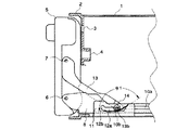
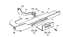
実施例について図面を参照して説明すると、図1は実施例に係る前面パネル装置の可動ノーズが起立している状態を示す要部断面図、図2は該前面パネル装置に備えられる可動ノーズの駆動機構を示す分解斜視図、図3は該前面パネル装置に備えられるスライド部材の駆動機構を示す平面図、図4は該可動ノーズが全開方向へ回動を開始した直後の状態を示す要部断面図、図5は該可動ノーズが全開している状態を示す要部断面図である。
【0015】
図1に示すように、車載用オーディオ装置のシャーシ1の前面に前面パネル2が固定されており、これらシャーシ1と前面パネル2によって本体装置の筐体が構成されている。前面パネル2には第1の挿入口3と第2の挿入口4が上下2段に開設されており、第1の挿入口3は例えばCDを挿入/排出するための開口であり、第2の挿入口4は例えばMDを挿入/排出するための開口である。前面パネル2の凹所内に可動ノーズ5が配置されており、第1および第2の挿入口3,4は可動ノーズ5の回動操作によって開閉される。この可動ノーズ5の表面には図示せぬ液晶ディスプレイや各種操作キー等が配設されており、また、可動ノーズ5の側面に下部支点である第1の支軸6と上部支点である第2の支軸7が上下方向に所定の間隔をおいて突設されている。なお、これら第1および第2の支軸6,7は可動ノーズの左右両側面にそれぞれ突設されている。
【0016】
図2と図3に示すように、シャーシ1の底面上にスライド部材8が配置されており、このスライド部材8には歯車9に噛合するラック8aが刻設されている。歯車9は図示せぬモータによって時計または反時計方向へ選択的に回転し、スライド部材8はこのモータを駆動源としてシャーシ1の前後方向に移動可能となっている。スライド部材8の左右両側面は上方に向けて直角に折り曲げられており、これら両側面の先端に穿設された軸孔8bを第1の支軸6に挿入することにより、可動ノーズ5とスライド部材8は第1の支軸6を回動支点として回動可能に連結されている。また、スライド部材8の両側面に可動側ガイド孔10が穿設されており、この可動側ガイド孔10は、シャーシ1の前後方向に沿って延びる第1の水平部10aと、第1の水平部10aの前端から斜め下方へ延びる第1のカム部10bとを有している。
【0017】
また、シャーシ1の底面上にL字状に折り曲げられた一対のブラケット11が固定されており、これらブラケット11の起立面はスライド部材8の両側面の外側に位置している。ブラケット11の起立面には固定側ガイド孔12が穿設されており、この固定側ガイド孔12は、シャーシ1の前後方向に沿って延びる第2の水平部12aと、第2の水平部12aの前端から斜め上方へ延びる第2のカム部12bとを有している。なお、固定側ガイド孔12はシャーシ1の側面に直接設けることも可能である。
【0018】
さらに、スライド部材8の両側面の内側にそれぞれ駆動アーム13が配置されており、これら駆動アーム13の先端に穿設された軸孔13aを第2の支軸7に挿入することにより、可動ノーズ5と駆動アーム13は第2の支軸7を回動支点として回動可能に連結されている。一方、駆動アーム13の後端側には外側へ向かって突出する軸部13bが設けられており、軸部13bはスライド部材8の可動側ガイド孔10とブラケット11の固定側ガイド孔12内に移動可能に挿入されている。軸部13bには捩じりコイルばね14が巻装されており、この捩じりコイルばね14の一方の腕部14aは駆動アーム13の後端の掛止部13cに掛止され、他方の腕部14bはスライド部材8の底面に弾接されている。なお、ブラケット11の外側から軸部13bに止めねじ15が螺入されており、この止めねじ15によって軸部13bが可動側ガイド孔10と固定側ガイド孔12から抜け落ちないようになっている。
【0019】
このように構成された前面パネル装置において、図1に示すように可動ノーズ5が起立状態にあるとき、前面パネル2に開設された第1および第2の挿入口3,4は可動ノーズ5によって覆い隠されており、スライド部材8はシャーシ1の最も奥側の後退位置にある。この場合、駆動アーム13の軸部13bは可動側ガイド孔10の第1のカム部10bと固定側ガイド孔12の第2の水平部12aの後端とに係合しており、捩じりコイルばね14の両腕部14a,14bの開放角度θ1は初期値(例えばθ1=154°)に設定されている。
【0020】
かかる可動ノーズ5の起立状態で図示せぬオープン釦を操作すると、前記モータが正転してその回転力が歯車9を介してラック8aに伝達され、スライド部材8が後退位置から前進位置への移動を開始する。スライド部材8が前進すると、軸部13bは可動側ガイド孔10の第1のカム部10bに係合したまま固定側ガイド孔12の第2の水平部12a内を前進し、この間、可動ノーズ5は起立状態を保ったまま所定量だけ前進し、捩じりコイルばね14の両腕部14a,14bの開放角度θ1は変化しない。
【0021】
スライド部材8がさらに前進すると、軸部13bが第2の水平部12aの前端に当接して停止するため、駆動アーム13の軸部13bに対してスライド部材8のみが前進する。その結果、図4に示すように、軸部13bが可動側ガイド孔10の第1のカム部10bから第1の水平部10aへ移行すると共に、固定側ガイド孔12の第2の水平部12aから第2のカム部12bへと移行し、可動ノーズ5が第1および第2の支軸6,7を回動支点として起立状態から全開方向へ回動し始める。このとき、軸部13bが第1および第2のカム部10b,12bに沿ってスライド部材8の移動方向と交差する斜め上方へ持ち上げられるため、この軸部13bに巻回されている捩じりコイルばね14の両腕部14a,14bの開放角度θ2(例えばθ2=162°)が初期値θ1よりも拡がり、捩じりコイルばね14のばね荷重は最小となる。
【0022】
スライド部材8がさらに前進すると、駆動アーム13の軸部13bは可動側ガイド孔10の第1の水平部10aの後端へと相対的に移行し、それに伴って可動ノーズ5の回動角度が大きくなると共に、捩じりコイルばね14の両腕部14a,14bの開放角度が前記θ2から狭められていき、捩じりコイルばね14のばね荷重が次第に増加する。そして、スライド部材8が前進位置まで移動すると、図5に示すように、可動ノーズ5はその下部側が手前側にせり出した全開(水平)状態となり、前面パネル2に開設された第1および第2の挿入口3,4が露出する。このとき、捩じりコイルばね14の両腕部14a,14bの開放角度θ3(例えばθ3=132°)は最も狭められ、捩じりコイルばね14のばね荷重は最大となる。
【0023】
また、可動ノーズ5が図5に示す全開状態にある時に図示せぬクローズ釦を操作すると、前記モータが逆転して上記と逆の動作が行われる。すなわち、スライド部材8が前進位置から後退位置への移動を開始し、それに伴って軸部13bが可動側ガイド孔10の第1の水平部10aの後端から第1のカム部10bへ移行すると共に、固定側ガイド孔12の第2のカム部12bから第2の水平部12aへ移行し、その後に水平部12aの後端に向かって移動することにより、可動ノーズ5は図1に示す起立状態に戻る。その際、スライド部材8と駆動アーム13は全開状態にある可動ノーズ5を起立させるのに大きな力を要するが、両腕部14a,14bの開放角度が狭められた捩じりコイルばね14によって可動ノーズ5の起立方向への回動が補足されるため、可動ノーズ5を起立位置までスムーズに回動させることができる。
【0024】
このように上記実施例に係る前面パネル装置では、スライド部材8が前進方向へ駆動される移動途中で、駆動アーム13の軸部13bが第1および第2のカム部10b,12bに沿って持ち上げられることにより、捩じりコイルばね14の両腕部14a,14bの開放角度が可動ノーズ5の起立時に設定された初期値θ1よりも一旦拡がり、しかる後、可動ノーズ5が全開方向へ回動するのに伴って捩じりコイルばね14の両腕部14a,14bの開放角度が次第に狭められていくため、起立状態にある可動ノーズ5のラットルノイズ防止を考慮して捩じりコイルばね14のばね加重を設定した場合、可動ノーズ5が起立位置から全開位置へ回動する途中で捩じりコイルばね14のばね加重を一旦小さくすることができる。したがって、可動ノーズ5の起立時におけるラットルノイズ防止を確保した上で、可動ノーズ5を起立位置から全開位置まで回動する時に必要とされる駆動力を小さくすることができ、小型のモータを用いてスライド部材8を駆動することができる。また、第1および第2のカム部10b,12bのカム形状を変更することによって、捩じりコイルばね14の両腕部14a,14bの最大開放角度を別の値に設定できるため、可動ノーズ5の起立時と回動途中時における捩じりコイルばね14のばね荷重を種々の値に設定できて設計上の自由度が向上する。
【0025】
さらに、スライド部材8に設けられた可動側ガイド孔10の第1の水平部10aの前端に第1のカム部10bを下方へ向けて形成すると共に、ブラケット11に設けられた固定側ガイド孔12の第2の水平部12aの前端に第2のカム部12bを上方へ向けて形成したので、スライド部材8の前進に伴って駆動アーム13の軸部13bが第2の水平部12aの後端から前端まで移動する間、可動ノーズ5を起立させた状態で前進させることができ、その後に可動ノーズ5を全開方向へ回動させることができるので、可動ノーズ5の背面側上部が回動時に前面パネル2に当接するのを防止できる。
【0026】
なお、上記実施例では、スライド部材8に第1のカム部10bを有する可動側ガイド孔10を設けると共に、本体装置側のブラケット11に第2のカム部12bを有する固定側ガイド孔12を設け、駆動アーム13の軸部13bがこれら可動側ガイド孔10と固定側ガイド孔12の両方に対して前後方向へ案内される場合について説明したが、いずれか一方のガイド孔を省略することも可能である。例えば、本体装置側に固定側ガイド孔の代わりに逃げ孔を設け、駆動アームの軸部が可動側ガイド孔のカム部から水平部へ移行する時に、軸部がこの逃げ孔に沿って上方へ移動するように構成したり、駆動アームの軸部を本体装置側に設けた固定側ガイド孔のみに案内させ、この固定側ガイド孔の前端にカム部を下方へ向けて形成することにより、スライド部材の前進移動に伴って軸部がカム部に沿って上方へ移動するように構成しても良い。
【0027】
【発明の効果】
本発明は、以上説明したような形態で実施され、以下に記載されるような効果を奏する。
【0028】
前後方向へ駆動されるスライド部材と協働して可動ノーズを回動させる駆動アームに軸部を設け、この軸部を本体装置の前後方向へ案内するガイド孔に、可動ノーズを起立方向へ付勢する捩じりコイルばねの両腕部の開放角度を拡げることが可能なカム部を形成したので、捩じりコイルばねのばね加重は可動ノーズを起立位置から全開方向へ回動する途中位置で少なくとも一旦は小さくなり、それ故、起立状態にある可動ノーズのラットルノイズ防止を考慮して捩じりコイルばねのばね加重を設定したとしても、この可動ノーズを全開位置まで小さな駆動力でスムーズに回動させることができると共に、全開位置で最大となった捩じりコイルばねのばね加重によって可動ノーズを起立位置までスムーズに回動させることができる。
【図面の簡単な説明】
【図1】実施例に係る前面パネル装置の可動ノーズが起立している状態を示す要部断面図である。
【図2】該前面パネル装置に備えられる可動ノーズの駆動機構を示す分解斜視図である。
【図3】該前面パネル装置に備えられるスライド部材の駆動機構を示す平面図である。
【図4】該可動ノーズが全開方向へ回動を開始した直後の状態を示す要部断面図である。
【図5】該可動ノーズが全開している状態を示す要部断面図である。
【符号の説明】
1 シャーシ
2 前面パネル
5 可動ノーズ
6 第1の支軸
7 第2の支軸
8 スライド部材
10 可動側ガイド孔
10a 第1の水平部
10b 第1のカム部
11 ブラケット
12 固定側ガイド孔
12a 第2の水平部
12b 第2のカム部
13 駆動アーム
13b 軸部
14 捩じりコイルばね
14a,14b 腕部[0001]
BACKGROUND OF THE INVENTION
The present invention relates to a front panel device of an in-vehicle electronic device in which a movable nose arranged on the front surface of a main body device rotates in conjunction with a reciprocating movement of a slide member, and in particular, a movable nose provided in the front panel device. The drive mechanism.
[0002]
[Prior art]
In recent years, an in-vehicle electronic device having a display screen such as a liquid crystal display has been remarkably spread. For example, in an in-vehicle electronic device such as an MD player and a CD player, an MD, a CD, etc. Since it is necessary to open an insertion slot for inserting / ejecting the medium, if a display screen and various operation keys are arranged on the front panel together with the insertion slot, a space for arranging the insertion slot and various operation keys is secured. Therefore, the display screen cannot be enlarged.
[0003]
On the other hand, for example, a front panel device of an in-vehicle electronic device disclosed in Japanese Patent Application Laid-Open No. 2000-76838 provides a medium insertion port in the front panel fixed to the front surface of the main body device and covers the front panel. A display screen and various operation keys are provided on the movable nose side, and the movable nose is rotated by a slide member to selectively open and close the insertion slot. The slide member is movable in the front-rear direction of the main body device using a motor as a drive source, and the support shafts provided on both lower side surfaces of the movable nose are rotatably connected to the tip of the slide member. A torsion coil spring is wound around the support shaft, and both arms of the torsion coil spring are hooked to the movable nose and the slide member. Further, guide grooves extending in the vertical direction are formed on both inner side walls of the opening of the main unit, and guide pins provided on both upper side surfaces of the movable nose are movably engaged with the guide grooves.
[0004]
In the front panel device schematically configured in this way, when the slide member is pulled into the retracted position, the movable nose is in an upright state, and the insertion opening opened in the front panel is covered by the movable nose. . At this time, the open angle of both arms of the torsion coil spring is the widest, and the movable nose is pressed against the front panel by the torsion coil spring, so that the vibration acts from the outside when the movable nose stands. Even so, the torsion coil spring can suppress the generation of abnormal noise called rattle noise. Then, when the motor is rotated in one direction and the slide member is moved from the retracted position to the advanced position with the movable nose standing, the pair of support shafts provided on both lower side surfaces of the movable nose are advanced together with the slide member. However, since the pair of guide pins provided on both sides of the upper part of the movable nose moves from the upper end to the lower end along the guide groove, the lower part of the movable nose is turned forward while rotating around the support shaft. The fully open (horizontal) state protruding to the side is exposed, and the insertion opening established in the front panel is exposed. At that time, with the rotation of the movable nose, the opening angle of both arms of the torsion coil spring is narrowed to gradually increase the spring load, and the spring load of the torsion coil spring is increased when the movable nose is fully open. Maximum.
[0005]
On the other hand, when the motor is rotated in the other direction with the movable nose fully opened to move the slide member from the forward position to the backward position, the guide pin moves from the lower end to the upper end along the guide groove. Then, the movable nose rotates around the support shaft as a rotation fulcrum, and the lower side thereof is pulled up to be in an upright state, and the insertion port is again covered with the movable nose. At that time, the slide member requires a large force to erect the movable nose in the fully opened state, but the reaction force of the sufficiently bent torsion coil spring acts in the direction to erect the movable nose. The rotation of the movable nose in the standing direction is supplemented by the torsion coil spring, and the movable nose can be smoothly rotated in the standing direction.
[0006]
[Problems to be solved by the invention]
By the way, in the above-mentioned conventional front panel device, when the movable nose starts to rotate in the fully open direction from the standing state, the opening angle of both arms of the torsion coil spring is gradually narrowed, and the torsion coil spring The spring load is minimum when the movable nose is up and maximum when the movable nose is fully open. That is, since the spring load of the torsion coil spring set in the standing state of the movable nose gradually increases at the intermediate position where the movable nose rotates in the fully open direction from the standing state, the slide member is smoothly advanced. However, not only a large driving force is required, but also a large mechanical strength is required for the guide mechanism of the slide member.
[0007]
Thus, in the above-described conventional front panel device, the spring load of the torsion coil spring changes proportionally according to the rotation angle of the movable nose, so that, for example, the torsion coil when the movable nose stands up If the opening angle of both arms of the spring is set to an initial value and the rattle noise can be reliably suppressed by the spring load of the torsion coil spring at this time, the spring of the coil spring at the intermediate position of the movable nose The load becomes undesirably large, and the slide member cannot be smoothly advanced unless a large motor with a large driving force is used. Therefore, the opening angle of both arms of the torsion coil spring when the movable nose is raised is set to a relatively large initial value so that the slide member can be smoothly advanced even with a small motor having a small driving force. In this case, the torsion coil spring is not sufficiently loaded when the movable nose is standing up, and the rattle noise cannot be reliably suppressed. Also, the torsion coil accompanying the rotation of the movable nose Since the opening and closing angles of both arms of the spring are remarkably wide, there arises a problem that the life of the torsion coil spring is reduced.
[0008]
The present invention has been made in view of such a state of the art, and its purpose is to smoothly rotate the movable nose with a small driving force while reliably suppressing the rattle noise when the movable nose is raised. An object of the present invention is to provide a front panel device for an in-vehicle electronic device.
[0009]
[Means for Solving the Problems]
According to the present invention, a shaft portion is provided in a drive arm that rotates a movable nose in cooperation with a slide member that is driven in the front-rear direction, and the movable nose is provided in a guide hole that guides the shaft portion in the front-rear direction of the main body device. A cam portion capable of expanding the opening angle of both arms of the torsion coil spring biased in the standing direction is formed. With this configuration, it is possible to prevent the spring load of the torsion coil spring from being proportionally increased at the midway position where the movable nose is rotated in the fully open direction from the standing position, so that the rattle noise of the movable nose in the standing state can be prevented. Even if the spring load of the torsion coil spring is set in consideration of prevention, the movable nose can be smoothly rotated to the fully open position with a relatively small driving force, and the maximum screw at the fully open position can be obtained. The movable nose can be smoothly rotated to the standing position by the spring load of the torsion coil spring.
[0010]
DETAILED DESCRIPTION OF THE INVENTION
In the front panel device of the in-vehicle electronic device according to the present invention, a movable nose disposed on the front surface of the main body device, and a slide member rotatably connected to a pair of lower fulcrums provided on both side surfaces of the movable nose. A drive means for reciprocating the slide member in the front-rear direction of the main body device; and a drive arm rotatably connected to a pair of upper fulcrums provided on both side surfaces of the movable nose. In a front panel device of an in-vehicle electronic device in which the movable nose rotates around the lower fulcrum as the member reciprocates, a guide hole for guiding the drive arm in the front-rear direction of the main body device, and the movable nose A torsion coil spring that is biased in a standing direction, and a shaft portion that is inserted into the guide hole and guided is provided on the drive arm, and the torsion coil spring is wound around the shaft portion. Together with the the guide hole and the shaft portion to form a guidable cam portion in a direction to expand the opening angle of both arm portions of and the torsion coil spring in the movement direction intersecting the direction of the slide member.
[0011]
In the front panel device thus configured, the opening angle of both arms of the torsion coil spring is set to an initial value when the movable nose is raised, and when the slide member is driven in the forward direction from this state. The opening angle of both arms of the torsion coil spring is at least temporarily expanded by the engagement of the shaft of the drive arm and the cam of the guide hole, and then the movable nose is moved by the relative movement of the shaft and the guide hole. Begins to rotate in the fully open direction, and the opening angle of both arms of the torsion coil spring is gradually narrowed accordingly. Therefore, since the spring load of the torsion coil spring does not increase proportionally during the rotation of the movable nose from the standing position in the fully open direction, the prevention of rattle noise of the movable nose in the standing state is considered. Even if the spring load of the torsion coil spring is set, the movable nose can be smoothly rotated to the fully open position with a small driving force, and the torsion coil spring spring maximized at the fully open position. The movable nose can be smoothly rotated to the standing position by weighting.
[0012]
In the above configuration, the guide hole may be provided in at least one of the slide member and the main body device, but the slide member is provided with a movable side guide hole as a guide hole, and the main body device has a fixed side as a guide hole. It is preferable to provide a guide hole and insert the shaft portion of the drive arm into the movable side guide hole and the fixed side guide hole. At that time, when the cam portion is formed downward at the front end of the movable guide hole and the cam portion is formed upward at the front end of the fixed side guide hole, the shaft portion extends from the rear end to the front end of the fixed side guide hole. The movable nose can be moved forward while moving up.
[0013]
Further, when the guide hole is provided in both the slide member and the main body device, one arm portion of the torsion coil spring is hooked to the drive arm and the other arm portion is elastically contacted to the slide member. It is preferable.
[0014]
【Example】
The embodiment will be described with reference to the drawings. FIG. 1 is a cross-sectional view of an essential part showing a state in which the movable nose of the front panel device according to the embodiment is standing, and FIG. 2 is a diagram of the movable nose provided in the front panel device. 3 is an exploded perspective view showing the drive mechanism, FIG. 3 is a plan view showing the drive mechanism of the slide member provided in the front panel device, and FIG. 4 is a main part showing a state immediately after the movable nose starts to rotate in the fully open direction. FIG. 5 is a cross-sectional view of the main part showing a state in which the movable nose is fully opened.
[0015]
As shown in FIG. 1, a
[0016]
As shown in FIGS. 2 and 3, a
[0017]
A pair of
[0018]
Furthermore, drive
[0019]
In the front panel device configured as described above, when the
[0020]
When an open button (not shown) is operated with the
[0021]
When the
[0022]
When the
[0023]
Further, when the close button (not shown) is operated when the
[0024]
Thus, in the front panel device according to the above-described embodiment, the
[0025]
Further, the
[0026]
In the above embodiment, the movable
[0027]
【The invention's effect】
The present invention is implemented in the form as described above, and has the following effects.
[0028]
A shaft is provided on the drive arm that rotates the movable nose in cooperation with the slide member driven in the front-rear direction, and the movable nose is attached in the upright direction to a guide hole that guides the shaft in the front-rear direction of the main unit. Because the cam part that can widen the opening angle of both arms of the torsion coil spring is formed, the spring load of the torsion coil spring is in the middle of rotating the movable nose from the standing position to the fully open direction Therefore, even if the spring load of the torsion coil spring is set considering the prevention of rattle noise of the movable nose in the standing state, the movable nose is smoothly moved to the fully open position with a small driving force. The movable nose can be smoothly rotated to the standing position by the spring load of the torsion coil spring that is maximized at the fully opened position.
[Brief description of the drawings]
FIG. 1 is a cross-sectional view of a main part showing a state in which a movable nose of a front panel device according to an embodiment is raised.
FIG. 2 is an exploded perspective view showing a drive mechanism of a movable nose provided in the front panel device.
FIG. 3 is a plan view showing a drive mechanism of a slide member provided in the front panel device.
FIG. 4 is a cross-sectional view of the main part showing a state immediately after the movable nose starts to rotate in the fully open direction.
FIG. 5 is a cross-sectional view of a main part showing a state in which the movable nose is fully opened.
[Explanation of symbols]
DESCRIPTION OF
Claims (5)
前記駆動アームを前記本体装置の前後方向へ案内するガイド孔と、前記可動ノーズを起立方向へ付勢する捩じりコイルばねとを備え、
前記駆動アームに前記ガイド孔に挿入されて案内される軸部を設け、この軸部に前記捩じりコイルばねを巻装すると共に、前記ガイド孔に、前記軸部を前記スライド部材の移動方向と交差する方向で且つ前記捩じりコイルばねの両腕部の開放角度を拡げる方向へ案内可能なカム部を形成したことを特徴とする車載用電子機器の前面パネル装置。A movable nose disposed on the front surface of the main unit, a slide member rotatably connected to a pair of lower fulcrums provided on both sides of the movable nose, and the slide member reciprocating in the front-rear direction of the main unit Drive means that moves, and a drive arm that is rotatably connected to a pair of upper fulcrums provided on both side surfaces of the movable nose, and the movable nose is moved to the lower fulcrum as the slide member reciprocates. In the front panel device of in-vehicle electronic equipment that rotates around
A guide hole that guides the drive arm in the front-rear direction of the main body device, and a torsion coil spring that biases the movable nose in a standing direction,
The drive arm is provided with a shaft portion that is inserted and guided in the guide hole, and the torsion coil spring is wound around the shaft portion, and the shaft portion is moved in the guide hole in the moving direction of the slide member. A front panel device for an in-vehicle electronic device, characterized in that a cam portion is formed that can be guided in a direction that intersects with the torsion coil spring and in a direction that widens the opening angle of both arms of the torsion coil spring.
Priority Applications (1)
| Application Number | Priority Date | Filing Date | Title |
|---|---|---|---|
| JP2002260215A JP3974005B2 (en) | 2002-09-05 | 2002-09-05 | Front panel device for in-vehicle electronic equipment |
Applications Claiming Priority (1)
| Application Number | Priority Date | Filing Date | Title |
|---|---|---|---|
| JP2002260215A JP3974005B2 (en) | 2002-09-05 | 2002-09-05 | Front panel device for in-vehicle electronic equipment |
Publications (2)
| Publication Number | Publication Date |
|---|---|
| JP2004103064A JP2004103064A (en) | 2004-04-02 |
| JP3974005B2 true JP3974005B2 (en) | 2007-09-12 |
Family
ID=32260995
Family Applications (1)
| Application Number | Title | Priority Date | Filing Date |
|---|---|---|---|
| JP2002260215A Expired - Fee Related JP3974005B2 (en) | 2002-09-05 | 2002-09-05 | Front panel device for in-vehicle electronic equipment |
Country Status (1)
| Country | Link |
|---|---|
| JP (1) | JP3974005B2 (en) |
Families Citing this family (4)
| Publication number | Priority date | Publication date | Assignee | Title |
|---|---|---|---|---|
| JP4598056B2 (en) * | 2005-03-09 | 2010-12-15 | パイオニア株式会社 | Electronics |
| KR100670562B1 (en) * | 2005-04-22 | 2007-01-17 | 주식회사 현대오토넷 | Pannel loadong device in car-audio system |
| JP4610459B2 (en) * | 2005-10-03 | 2011-01-12 | アルパイン株式会社 | Disk unit |
| JP2020024773A (en) * | 2018-08-08 | 2020-02-13 | 株式会社Jvcケンウッド | Electronic device and method for suppressing rattle noise of electronic device |
-
2002
- 2002-09-05 JP JP2002260215A patent/JP3974005B2/en not_active Expired - Fee Related
Also Published As
| Publication number | Publication date |
|---|---|
| JP2004103064A (en) | 2004-04-02 |
Similar Documents
| Publication | Publication Date | Title |
|---|---|---|
| JP5375289B2 (en) | Display device for vehicle seat | |
| JP4251498B2 (en) | Lid device | |
| JP3650274B2 (en) | Front panel device for in-vehicle equipment | |
| JP3974005B2 (en) | Front panel device for in-vehicle electronic equipment | |
| JP2010241358A (en) | Back board of vehicle seat | |
| JP4235457B2 (en) | Front panel device for in-vehicle electronic equipment | |
| JP4245451B2 (en) | Panel drive device for in-vehicle equipment | |
| JP4245528B2 (en) | Vehicle storage device | |
| EP1622155B1 (en) | Door interlock unit and disk recording/reproducing apparatus with the same | |
| CN110892218B (en) | Door opening and closing mechanism | |
| JP4503473B2 (en) | Vehicle storage structure | |
| EP1932716A1 (en) | Article stowage device for vehicle | |
| JP4171306B2 (en) | Front panel device for in-vehicle electronic equipment | |
| JP3820324B2 (en) | Front panel device for in-vehicle equipment | |
| JP4393796B2 (en) | Game machine | |
| JP4349478B2 (en) | Automotive electronic devices | |
| JP4662395B2 (en) | Automotive electronics | |
| JP6800530B2 (en) | In-vehicle display device | |
| JP4426994B2 (en) | Front panel device for in-vehicle equipment | |
| JP4470352B2 (en) | Game machine | |
| JP5606336B2 (en) | Panel drive device | |
| JP2003196966A (en) | Electronic appliance | |
| JP4115878B2 (en) | Latch device | |
| JP4416623B2 (en) | Electronic device display panel opening and closing mechanism | |
| JP4012295B2 (en) | Front panel operation mechanism in electronic equipment |
Legal Events
| Date | Code | Title | Description |
|---|---|---|---|
| A621 | Written request for application examination |
Free format text: JAPANESE INTERMEDIATE CODE: A621 Effective date: 20050329 |
|
| A977 | Report on retrieval |
Free format text: JAPANESE INTERMEDIATE CODE: A971007 Effective date: 20070201 |
|
| TRDD | Decision of grant or rejection written | ||
| A01 | Written decision to grant a patent or to grant a registration (utility model) |
Free format text: JAPANESE INTERMEDIATE CODE: A01 Effective date: 20070605 |
|
| A61 | First payment of annual fees (during grant procedure) |
Free format text: JAPANESE INTERMEDIATE CODE: A61 Effective date: 20070613 |
|
| R150 | Certificate of patent or registration of utility model |
Ref document number: 3974005 Country of ref document: JP Free format text: JAPANESE INTERMEDIATE CODE: R150 Free format text: JAPANESE INTERMEDIATE CODE: R150 |
|
| FPAY | Renewal fee payment (event date is renewal date of database) |
Free format text: PAYMENT UNTIL: 20100622 Year of fee payment: 3 |
|
| FPAY | Renewal fee payment (event date is renewal date of database) |
Free format text: PAYMENT UNTIL: 20110622 Year of fee payment: 4 |
|
| FPAY | Renewal fee payment (event date is renewal date of database) |
Free format text: PAYMENT UNTIL: 20120622 Year of fee payment: 5 |
|
| FPAY | Renewal fee payment (event date is renewal date of database) |
Free format text: PAYMENT UNTIL: 20120622 Year of fee payment: 5 |
|
| FPAY | Renewal fee payment (event date is renewal date of database) |
Free format text: PAYMENT UNTIL: 20130622 Year of fee payment: 6 |
|
| FPAY | Renewal fee payment (event date is renewal date of database) |
Free format text: PAYMENT UNTIL: 20130622 Year of fee payment: 6 |
|
| FPAY | Renewal fee payment (event date is renewal date of database) |
Free format text: PAYMENT UNTIL: 20140622 Year of fee payment: 7 |
|
| LAPS | Cancellation because of no payment of annual fees |