JP3973311B2 - Method and apparatus for producing polyimide film - Google Patents
Method and apparatus for producing polyimide film Download PDFInfo
- Publication number
- JP3973311B2 JP3973311B2 JP344399A JP344399A JP3973311B2 JP 3973311 B2 JP3973311 B2 JP 3973311B2 JP 344399 A JP344399 A JP 344399A JP 344399 A JP344399 A JP 344399A JP 3973311 B2 JP3973311 B2 JP 3973311B2
- Authority
- JP
- Japan
- Prior art keywords
- film
- surface treatment
- treatment liquid
- polyimide
- gel
- Prior art date
- Legal status (The legal status is an assumption and is not a legal conclusion. Google has not performed a legal analysis and makes no representation as to the accuracy of the status listed.)
- Expired - Fee Related
Links
- 229920001721 polyimide Polymers 0.000 title claims description 92
- 238000000034 method Methods 0.000 title claims description 48
- 108010025899 gelatin film Proteins 0.000 claims description 74
- 238000004381 surface treatment Methods 0.000 claims description 65
- 239000007788 liquid Substances 0.000 claims description 60
- 238000004519 manufacturing process Methods 0.000 claims description 35
- 239000004642 Polyimide Substances 0.000 claims description 31
- 238000010438 heat treatment Methods 0.000 claims description 30
- 230000008569 process Effects 0.000 claims description 16
- 239000002243 precursor Substances 0.000 claims description 15
- 239000003960 organic solvent Substances 0.000 claims description 13
- 238000005266 casting Methods 0.000 claims description 8
- 239000000463 material Substances 0.000 claims description 8
- 239000000243 solution Substances 0.000 description 22
- 239000000126 substance Substances 0.000 description 16
- 238000011282 treatment Methods 0.000 description 15
- 229920005575 poly(amic acid) Polymers 0.000 description 12
- 239000012756 surface treatment agent Substances 0.000 description 11
- 239000000853 adhesive Substances 0.000 description 10
- 230000001070 adhesive effect Effects 0.000 description 10
- 239000007822 coupling agent Substances 0.000 description 10
- 239000007789 gas Substances 0.000 description 9
- 238000007654 immersion Methods 0.000 description 9
- 239000002904 solvent Substances 0.000 description 8
- 238000001029 thermal curing Methods 0.000 description 8
- WFDIJRYMOXRFFG-UHFFFAOYSA-N Acetic anhydride Chemical compound CC(=O)OC(C)=O WFDIJRYMOXRFFG-UHFFFAOYSA-N 0.000 description 6
- YXFVVABEGXRONW-UHFFFAOYSA-N Toluene Chemical compound CC1=CC=CC=C1 YXFVVABEGXRONW-UHFFFAOYSA-N 0.000 description 6
- GTDPSWPPOUPBNX-UHFFFAOYSA-N ac1mqpva Chemical compound CC12C(=O)OC(=O)C1(C)C1(C)C2(C)C(=O)OC1=O GTDPSWPPOUPBNX-UHFFFAOYSA-N 0.000 description 6
- 125000003118 aryl group Chemical group 0.000 description 6
- 150000004985 diamines Chemical class 0.000 description 6
- 125000000962 organic group Chemical group 0.000 description 6
- 230000037303 wrinkles Effects 0.000 description 6
- 238000006243 chemical reaction Methods 0.000 description 5
- 238000001723 curing Methods 0.000 description 5
- 230000000694 effects Effects 0.000 description 5
- 239000003039 volatile agent Substances 0.000 description 5
- DLFVBJFMPXGRIB-UHFFFAOYSA-N Acetamide Chemical compound CC(N)=O DLFVBJFMPXGRIB-UHFFFAOYSA-N 0.000 description 4
- XKRFYHLGVUSROY-UHFFFAOYSA-N Argon Chemical compound [Ar] XKRFYHLGVUSROY-UHFFFAOYSA-N 0.000 description 4
- IJGRMHOSHXDMSA-UHFFFAOYSA-N Atomic nitrogen Chemical compound N#N IJGRMHOSHXDMSA-UHFFFAOYSA-N 0.000 description 4
- 230000000052 comparative effect Effects 0.000 description 4
- 238000003851 corona treatment Methods 0.000 description 4
- AWJUIBRHMBBTKR-UHFFFAOYSA-N isoquinoline Chemical compound C1=NC=CC2=CC=CC=C21 AWJUIBRHMBBTKR-UHFFFAOYSA-N 0.000 description 4
- 229920000642 polymer Polymers 0.000 description 4
- QTBSBXVTEAMEQO-UHFFFAOYSA-N Acetic acid Chemical compound CC(O)=O QTBSBXVTEAMEQO-UHFFFAOYSA-N 0.000 description 3
- RYGMFSIKBFXOCR-UHFFFAOYSA-N Copper Chemical group [Cu] RYGMFSIKBFXOCR-UHFFFAOYSA-N 0.000 description 3
- OKKJLVBELUTLKV-UHFFFAOYSA-N Methanol Chemical compound OC OKKJLVBELUTLKV-UHFFFAOYSA-N 0.000 description 3
- ZMXDDKWLCZADIW-UHFFFAOYSA-N N,N-Dimethylformamide Chemical compound CN(C)C=O ZMXDDKWLCZADIW-UHFFFAOYSA-N 0.000 description 3
- ISWSIDIOOBJBQZ-UHFFFAOYSA-N Phenol Chemical compound OC1=CC=CC=C1 ISWSIDIOOBJBQZ-UHFFFAOYSA-N 0.000 description 3
- 239000004809 Teflon Substances 0.000 description 3
- 229920006362 Teflon® Polymers 0.000 description 3
- RTAQQCXQSZGOHL-UHFFFAOYSA-N Titanium Chemical compound [Ti] RTAQQCXQSZGOHL-UHFFFAOYSA-N 0.000 description 3
- 239000002253 acid Substances 0.000 description 3
- 229910052782 aluminium Inorganic materials 0.000 description 3
- 239000003795 chemical substances by application Substances 0.000 description 3
- 239000011248 coating agent Substances 0.000 description 3
- 238000000576 coating method Methods 0.000 description 3
- 238000001035 drying Methods 0.000 description 3
- 238000010292 electrical insulation Methods 0.000 description 3
- 230000006872 improvement Effects 0.000 description 3
- 229910052757 nitrogen Inorganic materials 0.000 description 3
- 239000009719 polyimide resin Substances 0.000 description 3
- 239000000047 product Substances 0.000 description 3
- 125000006158 tetracarboxylic acid group Chemical group 0.000 description 3
- 239000010936 titanium Substances 0.000 description 3
- 229910052719 titanium Inorganic materials 0.000 description 3
- YEJRWHAVMIAJKC-UHFFFAOYSA-N 4-Butyrolactone Chemical class O=C1CCCO1 YEJRWHAVMIAJKC-UHFFFAOYSA-N 0.000 description 2
- CSCPPACGZOOCGX-UHFFFAOYSA-N Acetone Chemical compound CC(C)=O CSCPPACGZOOCGX-UHFFFAOYSA-N 0.000 description 2
- IAZDPXIOMUYVGZ-UHFFFAOYSA-N Dimethylsulphoxide Chemical compound CS(C)=O IAZDPXIOMUYVGZ-UHFFFAOYSA-N 0.000 description 2
- LFQSCWFLJHTTHZ-UHFFFAOYSA-N Ethanol Chemical compound CCO LFQSCWFLJHTTHZ-UHFFFAOYSA-N 0.000 description 2
- ZHNUHDYFZUAESO-UHFFFAOYSA-N Formamide Chemical compound NC=O ZHNUHDYFZUAESO-UHFFFAOYSA-N 0.000 description 2
- KFZMGEQAYNKOFK-UHFFFAOYSA-N Isopropanol Chemical compound CC(C)O KFZMGEQAYNKOFK-UHFFFAOYSA-N 0.000 description 2
- LRHPLDYGYMQRHN-UHFFFAOYSA-N N-Butanol Chemical compound CCCCO LRHPLDYGYMQRHN-UHFFFAOYSA-N 0.000 description 2
- SECXISVLQFMRJM-UHFFFAOYSA-N N-Methylpyrrolidone Chemical compound CN1CCCC1=O SECXISVLQFMRJM-UHFFFAOYSA-N 0.000 description 2
- CTQNGGLPUBDAKN-UHFFFAOYSA-N O-Xylene Chemical compound CC1=CC=CC=C1C CTQNGGLPUBDAKN-UHFFFAOYSA-N 0.000 description 2
- JUJWROOIHBZHMG-UHFFFAOYSA-N Pyridine Chemical compound C1=CC=NC=C1 JUJWROOIHBZHMG-UHFFFAOYSA-N 0.000 description 2
- SMWDFEZZVXVKRB-UHFFFAOYSA-N Quinoline Chemical compound N1=CC=CC2=CC=CC=C21 SMWDFEZZVXVKRB-UHFFFAOYSA-N 0.000 description 2
- 239000003513 alkali Substances 0.000 description 2
- 239000012670 alkaline solution Substances 0.000 description 2
- XAGFODPZIPBFFR-UHFFFAOYSA-N aluminium Chemical compound [Al] XAGFODPZIPBFFR-UHFFFAOYSA-N 0.000 description 2
- 229910052786 argon Inorganic materials 0.000 description 2
- 239000002585 base Substances 0.000 description 2
- 238000001816 cooling Methods 0.000 description 2
- 239000011889 copper foil Substances 0.000 description 2
- 239000012024 dehydrating agents Substances 0.000 description 2
- 125000000524 functional group Chemical group 0.000 description 2
- 239000011261 inert gas Substances 0.000 description 2
- 238000009434 installation Methods 0.000 description 2
- RLSSMJSEOOYNOY-UHFFFAOYSA-N m-methyl-PhOH Natural products CC1=CC=CC(O)=C1 RLSSMJSEOOYNOY-UHFFFAOYSA-N 0.000 description 2
- QWVGKYWNOKOFNN-UHFFFAOYSA-N o-methyl phenol Natural products CC1=CC=CC=C1O QWVGKYWNOKOFNN-UHFFFAOYSA-N 0.000 description 2
- IWDCLRJOBJJRNH-UHFFFAOYSA-N p-cresol Chemical compound CC1=CC=C(O)C=C1 IWDCLRJOBJJRNH-UHFFFAOYSA-N 0.000 description 2
- FDPIMTJIUBPUKL-UHFFFAOYSA-N pentan-3-one Chemical compound CCC(=O)CC FDPIMTJIUBPUKL-UHFFFAOYSA-N 0.000 description 2
- 238000009832 plasma treatment Methods 0.000 description 2
- 239000002994 raw material Substances 0.000 description 2
- 239000011347 resin Substances 0.000 description 2
- 229920005989 resin Polymers 0.000 description 2
- 238000010583 slow cooling Methods 0.000 description 2
- 239000002002 slurry Substances 0.000 description 2
- 239000007787 solid Substances 0.000 description 2
- 238000005507 spraying Methods 0.000 description 2
- 229920001169 thermoplastic Polymers 0.000 description 2
- 239000004416 thermosoftening plastic Substances 0.000 description 2
- XLYOFNOQVPJJNP-UHFFFAOYSA-N water Substances O XLYOFNOQVPJJNP-UHFFFAOYSA-N 0.000 description 2
- 239000008096 xylene Substances 0.000 description 2
- 150000005206 1,2-dihydroxybenzenes Chemical class 0.000 description 1
- VLDPXPPHXDGHEW-UHFFFAOYSA-N 1-chloro-2-dichlorophosphoryloxybenzene Chemical compound ClC1=CC=CC=C1OP(Cl)(Cl)=O VLDPXPPHXDGHEW-UHFFFAOYSA-N 0.000 description 1
- RNFJDJUURJAICM-UHFFFAOYSA-N 2,2,4,4,6,6-hexaphenoxy-1,3,5-triaza-2$l^{5},4$l^{5},6$l^{5}-triphosphacyclohexa-1,3,5-triene Chemical compound N=1P(OC=2C=CC=CC=2)(OC=2C=CC=CC=2)=NP(OC=2C=CC=CC=2)(OC=2C=CC=CC=2)=NP=1(OC=1C=CC=CC=1)OC1=CC=CC=C1 RNFJDJUURJAICM-UHFFFAOYSA-N 0.000 description 1
- DTQHSUHILQWIOM-UHFFFAOYSA-J 2-hydroxypropanoate titanium(4+) dihydroxide Chemical compound O[Ti++]O.CC(O)C([O-])=O.CC(O)C([O-])=O DTQHSUHILQWIOM-UHFFFAOYSA-J 0.000 description 1
- BSKHPKMHTQYZBB-UHFFFAOYSA-N 2-methylpyridine Chemical compound CC1=CC=CC=N1 BSKHPKMHTQYZBB-UHFFFAOYSA-N 0.000 description 1
- HLBLWEWZXPIGSM-UHFFFAOYSA-N 4-Aminophenyl ether Chemical compound C1=CC(N)=CC=C1OC1=CC=C(N)C=C1 HLBLWEWZXPIGSM-UHFFFAOYSA-N 0.000 description 1
- SUAKHGWARZSWIH-UHFFFAOYSA-N N,N‐diethylformamide Chemical compound CCN(CC)C=O SUAKHGWARZSWIH-UHFFFAOYSA-N 0.000 description 1
- WHNWPMSKXPGLAX-UHFFFAOYSA-N N-Vinyl-2-pyrrolidone Chemical compound C=CN1CCCC1=O WHNWPMSKXPGLAX-UHFFFAOYSA-N 0.000 description 1
- 239000004677 Nylon Substances 0.000 description 1
- 239000004962 Polyamide-imide Substances 0.000 description 1
- 239000004697 Polyetherimide Substances 0.000 description 1
- BLRPTPMANUNPDV-UHFFFAOYSA-N Silane Chemical compound [SiH4] BLRPTPMANUNPDV-UHFFFAOYSA-N 0.000 description 1
- 238000010521 absorption reaction Methods 0.000 description 1
- 150000008065 acid anhydrides Chemical class 0.000 description 1
- 239000003570 air Substances 0.000 description 1
- 239000005456 alcohol based solvent Substances 0.000 description 1
- 239000003963 antioxidant agent Substances 0.000 description 1
- 230000003078 antioxidant effect Effects 0.000 description 1
- 239000002216 antistatic agent Substances 0.000 description 1
- 150000004984 aromatic diamines Chemical class 0.000 description 1
- 150000004945 aromatic hydrocarbons Chemical class 0.000 description 1
- 239000012298 atmosphere Substances 0.000 description 1
- 230000015572 biosynthetic process Effects 0.000 description 1
- 125000002915 carbonyl group Chemical group [*:2]C([*:1])=O 0.000 description 1
- 239000003054 catalyst Substances 0.000 description 1
- 230000008859 change Effects 0.000 description 1
- 238000013329 compounding Methods 0.000 description 1
- 229910052802 copper Inorganic materials 0.000 description 1
- 239000010949 copper Substances 0.000 description 1
- 238000010586 diagram Methods 0.000 description 1
- -1 diamine compound Chemical class 0.000 description 1
- CCAFPWNGIUBUSD-UHFFFAOYSA-N diethyl sulfoxide Chemical compound CCS(=O)CC CCAFPWNGIUBUSD-UHFFFAOYSA-N 0.000 description 1
- 238000007598 dipping method Methods 0.000 description 1
- 229920001971 elastomer Polymers 0.000 description 1
- 229920006332 epoxy adhesive Polymers 0.000 description 1
- 239000012467 final product Substances 0.000 description 1
- 239000003063 flame retardant Substances 0.000 description 1
- 238000013007 heat curing Methods 0.000 description 1
- 239000012760 heat stabilizer Substances 0.000 description 1
- GNOIPBMMFNIUFM-UHFFFAOYSA-N hexamethylphosphoric triamide Chemical class CN(C)P(=O)(N(C)C)N(C)C GNOIPBMMFNIUFM-UHFFFAOYSA-N 0.000 description 1
- 229930195733 hydrocarbon Natural products 0.000 description 1
- 150000002430 hydrocarbons Chemical class 0.000 description 1
- 238000006358 imidation reaction Methods 0.000 description 1
- 238000002347 injection Methods 0.000 description 1
- 239000007924 injection Substances 0.000 description 1
- 239000011256 inorganic filler Substances 0.000 description 1
- 229910003475 inorganic filler Inorganic materials 0.000 description 1
- 238000009413 insulation Methods 0.000 description 1
- 239000005453 ketone based solvent Substances 0.000 description 1
- 238000010030 laminating Methods 0.000 description 1
- 239000004611 light stabiliser Substances 0.000 description 1
- 229910052751 metal Inorganic materials 0.000 description 1
- 239000002184 metal Substances 0.000 description 1
- 239000012046 mixed solvent Substances 0.000 description 1
- 238000002156 mixing Methods 0.000 description 1
- 239000000203 mixture Substances 0.000 description 1
- 238000012986 modification Methods 0.000 description 1
- 230000004048 modification Effects 0.000 description 1
- 210000003205 muscle Anatomy 0.000 description 1
- AJFDBNQQDYLMJN-UHFFFAOYSA-N n,n-diethylacetamide Chemical compound CCN(CC)C(C)=O AJFDBNQQDYLMJN-UHFFFAOYSA-N 0.000 description 1
- 229920001778 nylon Polymers 0.000 description 1
- XNLICIUVMPYHGG-UHFFFAOYSA-N pentan-2-one Chemical compound CCCC(C)=O XNLICIUVMPYHGG-UHFFFAOYSA-N 0.000 description 1
- 150000002989 phenols Chemical class 0.000 description 1
- 239000002798 polar solvent Substances 0.000 description 1
- 229920003055 poly(ester-imide) Polymers 0.000 description 1
- 229920002312 polyamide-imide Polymers 0.000 description 1
- 229920001601 polyetherimide Polymers 0.000 description 1
- 229920006254 polymer film Polymers 0.000 description 1
- 238000006116 polymerization reaction Methods 0.000 description 1
- 230000000379 polymerizing effect Effects 0.000 description 1
- BDERNNFJNOPAEC-UHFFFAOYSA-N propan-1-ol Chemical compound CCCO BDERNNFJNOPAEC-UHFFFAOYSA-N 0.000 description 1
- UMJSCPRVCHMLSP-UHFFFAOYSA-N pyridine Natural products COC1=CC=CN=C1 UMJSCPRVCHMLSP-UHFFFAOYSA-N 0.000 description 1
- HNJBEVLQSNELDL-UHFFFAOYSA-N pyrrolidin-2-one Chemical compound O=C1CCCN1 HNJBEVLQSNELDL-UHFFFAOYSA-N 0.000 description 1
- 230000035484 reaction time Effects 0.000 description 1
- 239000012744 reinforcing agent Substances 0.000 description 1
- 229910000077 silane Inorganic materials 0.000 description 1
- 150000003462 sulfoxides Chemical class 0.000 description 1
- 229920003002 synthetic resin Polymers 0.000 description 1
- 239000000057 synthetic resin Substances 0.000 description 1
- 150000003512 tertiary amines Chemical class 0.000 description 1
- 229920001187 thermosetting polymer Polymers 0.000 description 1
- 125000002256 xylenyl group Chemical class C1(C(C=CC=C1)C)(C)* 0.000 description 1
Images


Landscapes
- Moulding By Coating Moulds (AREA)
- Compositions Of Macromolecular Compounds (AREA)
- Manufacture Of Macromolecular Shaped Articles (AREA)
- Treatments Of Macromolecular Shaped Articles (AREA)
Description
【0001】
【発明の属する技術分野】
本発明は、ポリイミドフィルムの製造方法および製造装置に関し、特に接着性付与するために、表面処理液を施す方法及び装置に関する。
【0002】
【従来の技術】
ポリイミドは、耐熱性、耐寒性、耐薬品性、電気絶縁性、機械的強度等について優れた諸特性を有することが知られており、電気絶縁フィルム、断熱性フィルム、フレキシブルプリント配線板のベースフィルム等に広く利用されている。特に、フレキシブル配線基板や電気絶縁フィルム等の用途において、具体的にはポリイミドフィルムを接着剤を介して銅箔と接着して胴張積層板としたり、接着剤コーティングによりプリプレグ化したり、またフッ素樹脂との複合化をする等の用途に多く用いられている。従って、フィルムの接着能力は重要な特性となっており、接着性の改善が種々図られている。
【0003】
ところで、高分子フィルムに接着性を付与する技術には、フィルム製造後の後処理として、例えば、火炎処理、コロナ処理、紫外線処理、アルカリ処理、サンドブラスト処理、プラズマ処理等がある。これら一般的技術において、ポリイミドフィルムにその特性を維持しつつ接着性を向上させる目的に適用する方法が選択され、カップリング剤やアルカリ溶液等液体による各種表面処理がポリイミドフィルムの接着性付与に用いられている。
【0004】
現在行われている表面処理には、(i)ポリイミド前駆体溶液に表面処理剤を混入する方法、(ii)製造されたポリイミドフィルムに表面処理剤を塗布する方法がある。
【0005】
具体的には、上記(i)の方法は、ポリイミド製造工程において、ポリイミド前駆体であるポリアミド酸の有機溶媒溶液中に表面カップリング剤を混合してから、流延塗布し加熱することによりポリイミドフィルムを製造する方法である。また、上記(ii)の方法は、ポリイミド前駆体を流延塗布し加熱して製造されたポリイミドフィルムに表面処理剤を塗布し、乾燥工程を経て、該フィルムの接着性を向上する方法である。
【0006】
【発明が解決しようとする課題】
しかしながら、上記(i)の方法においては、表面処理剤がフィルム表面以外にフィルム内部にも必要であることより、表面処理剤を大量に消費するという問題がある。また、上記(ii)の方法は、完成したフィルムに表面処理剤が十分浸透することが困難であるため、表面処理剤の接着性向上への効果が少ないという問題がある。
【0007】
【課題を解決するための手段】
本発明者らは、鋭意検討の結果、上記問題を解決し、表面処理剤による接着力向上の効果を十分発揮させるべく、ゲルフィルムへの表面処理剤の処理方法及び装置を開発し、本発明を完成するに至った。
【0008】
本発明の第1は、ポリイミドの前駆体物質を含む有機溶媒溶液を流延塗布後加熱しゲルフィルムを形成する工程と、前記ゲルフィルムを表面処理液に浸漬する工程と、前記表面処理液に浸漬されたゲルフィルムを該表面処理液から引き上げる工程と、引き上げられた前記ゲルフィルムをフィルム端部支持手段により支持する工程と、前記ゲルフィルムの端部に圧縮気体をあてて、該ゲルフィルムの端部の前記表面処理液を除去する工程と、前記ゲルフィルムの表面の中央部分の剰余の前記表面処理液を除去ロールにより除去する工程 と、さら熱処理を施す工程とを含むことを特徴とするポリイミドフィルムの製造方法である。
【0009】
本発明の第2は、前記表面処理液に浸漬されたゲルフィルムが、該表面処理液から略垂直に引き上げられることを特徴とするポリイミドフィルムの製造方法である。
【0010】
本発明の第3は、前記フィルム端部支持手段が、複数のフィルム端部支持用ピンチロールであることを特徴とするポリイミドフィルムの製造方法である。
【0011】
本発明の第4は、前記除去ロールが、テフロン(登録商標)を用いたニップロールであることを特徴とするポリイミドフィルムの製造方法である。
【0012】
本発明の第5は、前記中央部分が、前記ゲルフィルムの両端から30mmより内側の範囲であることを特徴とするポリイミドフィルムの製造方法である。
【0013】
本発明の第6は、前記圧縮気体がエアノズルから噴射されてなり、前記エアノズルは、前記ゲルフィルムの端部付近の表面の前記表面処理液を中央方向に移動し得る気体噴射角度を保持し、かつフィルム外側からフィルム中央方向に向かって1対として設定されることを特徴とするポリイミドフィルムの製造方法である。
【0014】
本発明の第7は、前記エアノズルが、フィルム幅方向に対して10度以上90度以下の角度、かつフィルム進行方向に対して10度以上90度以下の角度に保持され、噴射した前記圧縮気体が前記ゲルフィルムの端部にあたるように構成されていることを特徴とするポリイミドフィルムの製造方法である。
【0015】
本発明の第8は、前記端部が、前記ゲルフィルムの両端から30mmの範囲であることを特徴とするポリイミドフィルムの製造方法である。
【0016】
本発明の第9は、前記フィルム端部支持用ピンチロールが、前記ゲルフィルムの両端部に設置され、フィルムの表面及び裏面からフィルム端部を各1対で挟持し、かつフィルム進行方向に対して10度以上90度以下の角度に保持されていることを特徴とするポリイミドフィルムの製造方法である。
【0017】
本発明の第10は、表面処理液が蓄えられて、ポリイミドの前駆体物質を含む有機溶媒溶液を流延塗布後加熱して形成されたゲルフィルムが浸漬される、表面処理液槽と、前記表面処理液に浸漬されたゲルフィルムを引き上げるガイドロールと、引き上げられた前記ゲルフィルムを支持するフィルム端部支持手段と、前記フィルム端部支持手段で支持されたゲルフィルムの端部に圧縮気体を噴射するエアノズルと、前記ゲルフィルムの表面の中央部分の剰余の前記表面処理液を除去する除去ロールと、前記剰余の表面処理液が除去されたゲルフィルムに熱処理を施すテンター室とを備えるポリイミドフィルムの製造装置である。
【0018】
本発明の第11は、前記表面処理液に浸漬されたゲルフィルムが、前記ガイドロールを介して該表面処理液から略垂直に引き上げられることを特徴とするポリイミドフィルムの製造装置である。
【0019】
本発明の第12は、前記フィルム端部支持手段が、複数のフィルム端部支持用ピンチロールであることを特徴とするポリイミドフィルムの製造装置である。
【0020】
【発明の実施の形態】
以下、本発明にかかるポリイミドフィルムの製造方法及びその装置について、実施の形態の1例に基づいて、説明するが本発明はこれらに限定されない。
【0021】
一般に、ポリイミドフィルムは不溶不融であるため、その前駆体物質の有機溶媒溶液をドラムあるいはベルト等の支持体に流延塗布するソルベントキャスト法が用いられ、本発明にかかるポリイミドフィルムの製造方法においても、この方法を用いる。
【0022】
以下、本発明にかかるポリイミドフィルムの製造方法及びその装置について、具体的に説明する。
【0023】
本発明にかかるポリイミドフィルムは、公知の各種原料から得られるものであり、特に限定されるものではなく、主として有機テトラカルボン酸二無水物と有機ジアミンとを原料として用い、各成分を実質的に等モル使用し、有機溶媒溶液中で重合して得られる。
【0024】
本発明にかかるポリイミドフィルムは、広義のポリイミドからなるフィルムであり、ポリイミド、ポリアミドイミド、ポリエーテルイミド、ポリエステルイミドなどを例示することができ、非熱可塑性、熱可塑性、熱硬化性等特に限定されない。即ち、ポリイミドの分子構造は問わない。あえて、例示するとすれば、好ましくは、下記の一般構造式(1)化1
【化1】

【0025】
式中、R1は4価の有機基であり、具体的には、少なくとも1個の芳香族を有してなり、かつ結合すべき隣接するカルボニル基とは芳香環が直接結合してなる。さらに具体的には、化2
【化2】
【化3】
【0026】
また、式中、R2は2価の有機基、具体的には少なくとも1個の芳香族を有してなり、
さらに、具体的には、化4
【化4】
【0027】
特に好ましいポリイミドは、式中、R1が、化5
【化5】
【化6】
【化7】
【化8】
【化9】
【0028】
さらに好ましくは、化10
【化10】
【化11】
【数1】
【化12】
【化13】
【化14】
【化15】
【化16】
【化17】
【0029】
以下、ポリイミド樹脂の製造方法について説明する。上記一般式(1)で表されるポリイミド樹脂は、その前駆体であるポリアミド酸重合体を脱水閉環して得られるが、このポリアミド酸溶液は、従来公知の方法により、酸二無水物とジアミン成分を実質的に等モル使用し、有機極性溶媒中で重合して得られる。
【0030】
まず、ポリアミド酸の製法について述べる。まず、アルゴン、窒素などの不活性ガス雰囲気中において、一般式(2)化18
【化18】
H2N−R2−NH2 (3)
(式中、R2は2価の有機基を示す。)で表される少なくとも1種以上のジアミン成分を有機溶媒に溶解、あるいは、スラリー状に拡散させた状態で、または、固体の状態で添加し、ポリアミド酸重合体の溶液を得る。
【0031】
この時の反応温度は、−10℃から50℃が好ましい。反応時間は、30分から6時間程度である。
【0032】
また、この反応において、上記添加順序とは逆に、まず、ジアミン成分を拡散又は溶解させ、該溶液中に酸二無水物の固体もしくは有機溶媒による溶液もしくはスラリーを添加してもよい。
【0033】
なお、生成されるポリイミド樹脂の強度を維持するためには、数平均分子量が1万以上が好ましい。ポリイミド重合体の分子量は直接測定が困難な場合が多い。このようなときには間接的な方法によって推測による測定がなされる。たとえば、ポリイミド重合体がポリアミド酸から合成される場合には、ポリアミド酸の分子量に相当する値をポリイミドの分子量とする。
【0034】
また、一般式(2)化19
【化19】
【化20】
【化21】
【0035】
また、一般式(3)で表されるジアミン化合物としては、本質的に種々のジアミンが使用可能であるが、より具体的には、諸特性のバランスから、一般式(3)
H2N−R2−NH2 (3)
中のR2が、化22
【化22】
【0036】
さらに、本発明に用いられ得る有機溶媒としては、例えば、ジメチルスルホキシド、ジエチルスルホキシドなどのスルホキシド系溶媒、N,N−ジメチルホルムアミド、N,N−ジエチルホルムアミドなどのホルムアミド系溶媒、N,N−ジメチルアセトアミド、N,N−ジエチルアセトアミドなどのアセトアミド系溶媒、N−メチル−2−ピロリドン、N−ビニル−2−ピロリドンなどのピロリドン系溶媒、フェノール、o−、m−、またはp−クレゾール、キシレノール、ハロゲン化フェノール、カテコールなどのフェノール系溶媒、あるいはヘキサメチルホスホルアミド、γ−ブチロラクトンなどをあげることができ、これらを単独または混合物として用いるのが望ましいが、更にはキシレン、トルエンのような芳香族炭化水素の一部使用も可能である。
【0037】
なお、ポリアミド酸溶液を調製する際、あるいはポリアミド酸溶液を調製した後、または化学的方法による脱水剤及び触媒に酸化防止剤、光安定剤,難燃剤、帯電防止剤、熱安定剤、紫外線吸収剤、あるいは無機フィラー類、またはその他の強化剤等を混合し得る。
【0038】
また、ポリイミドの製造方法は、前駆体であるポリアミド酸に無水酢酸等の酸無水物に代表される脱水閉環剤と、ピコリン、キノリン、イソキノリン、ピリジン等の第3級アミン類とを作用させるケミカルキュア法によってポリイミドに変換させる方法および、上記脱水剤等を作用させずに加熱のみでイミド化反応を進行させるいわゆる熱キュア法も用い得る。さらに両者を併用した方法も用い得る。
【0039】
ケミカルキュア法及び熱キュア法を組み合わせた場合、通常、工程の前半は主にケミカルキュア法が行われ、引き続き後半の熱キュア法でイミド化を完結する。
【0040】
ここで、本発明における「ゲルフィルム」とは、前半のケミカルキュアの工程が終了した段階のフィルム、あるいは熱キュア法による熱キュア工程に入る前のフィルムと、定義する。
【0041】
ポリイミド前駆体をイミド化し、最終的にポリイミドフィルムの製品とするための製造方法は、流延塗布しケミカルキュアを行う加熱手段を備えたドラム室あるいはベルト室と熱キュアを行うテンター室とに分けられる。
【0042】
本発明にかかるポリイミドフィルムの製造工程の1例を図1により示すと、まずベルト室10での工程は、ミキサーで混合したポリイミド前駆体をTダイ12によりフィルム状に押し出す工程を行い、反応硬化室においてはTダイより押し出されたフィルム状のポリイミド前駆体をエンドレスベルトあるいはキャスティングドラム14上にフィルム状に形成する。フィルム状に形成された前駆体は、ベルトあるいはドラムの回転により移動させられながら、加熱手段により加熱されてイミド化される。このベルト室内においては反応に伴って生成した生成物、主として水、酢酸、有機溶媒等が蒸発する。
【0043】
加熱手段は、樹脂から蒸散した可燃性の揮発成分に引火する危険を防止するため、あるいは樹脂自体が発火することを防止するために、雰囲気温度、およびベルトあるいはドラムの回転速度を調整しつつ加熱し、たとえば温風・熱風・放射熱による加熱、ベルト加熱等を用い得る。
【0044】
これらの工程により、ポリイミド前駆体のフィルムをイミド化しながら、フィルムが自己支持性を有する程度まで加熱・乾燥を行った後、エンドレスベルトまたはキャスティングドラムから引き剥がして、本発明にいうゲルフィルム16を得る。
【0045】
ところで、通常フィルムを上記工程を通して搬送しつつイミド化を行う場合において、ゲルフィルムの形状及び表面状態を最良に保持しフィルムの剥がれ・しわ等の表面上の難点を防止し、自己支持性を有するフィルムを搬送上・加工上の問題なく製造する指標として、残揮発物量の測定が行われている。
【0046】
本発明において、フィルム中の残揮発物量は、下記の式、数2
【数2】
W0:450℃20分間加熱処理後の重量
【0047】
通常上、エンドレスベルトまたはドラムなどの支持体より剥離されるフィルムの残揮発物量は、20〜200重量%の範囲内で行われる。残揮発物量が、200重量%を超えるとベルトまたはドラムから剥がれにくい、また剥離後のフィルムの自己支持性が良好でない等の問題が生じる。一方残揮発物量は20重量%未満以下である場合は、膜剥離の工程よりも前の段階でゲルフィルムが支持体より剥がれてベルトまたはドラム上から浮き上がり、搬送が不安定となる問題や、逆にフィルムが支持体より剥がれにくくなる場合がある等の問題が生じるためである。
【0048】
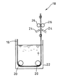
上記のようにして得られたゲルフィルムは、本発明に用いられるゲルフィルムの表面処理液浸漬工程18を経る。具体的に説明すると、ゲルフィルムは表面処理液浸漬工程18において、ガイドロール20により表面処理液槽22に導入される。表面処理液で処理されたゲルフィルムは、エアノズル24により圧縮空気を噴射された後、ロール26により均一に表面処理液を付着させられる。表面処理液浸漬工程18を経たゲルフィルム28は、テンター室30に導入される。テンター室30において、ゲルフィルムは、端部を固定され加熱処理される。たとえば、図1に示すように、ピンでフィルムを固定したピンシートをピンコンベアの回転駆動により移動させることによりフィルムをテンター室内で移動させる。テンター室では、熱キュアを行う加熱炉内において徐々に加熱することによりゲルフィルムをさらにイミド化する。加熱炉は通常200℃程度の温度から徐々に昇温しポリイミドへのイミド化を完了させ、ポリイミドフィルム32を得る。
【0049】
図2は、本発明にかかるポリイミドフィルムの製造装置において、表面処理液浸漬工程を表した模式図である。矢印はゲルフィルムの進行方向である。ベルト室を経たゲルフィルムは、ガイドロール20に導かれながら、表面処理液が満たされた表面処理液槽22に浸漬される。ゲルフィルムは、この表面処理液浸漬工程を経た後、さらに加熱されるため、表面処理液は加熱温度においても変質しない耐熱性を有することが必要である。具体的には、本発明において用いる表面処理液とは、アルカリ溶液も用い得るが、主としてシラン系、チタン系、アルミニウム系、又はジルコアルミニウム系のカップリング剤が挙げられ、これらカップリング剤は単独でも、数種を混合してもよく、特にはチタン系カップリング剤を用いることが好ましい。特に、下記一般式(4)化23
【化23】
【0050】
なお、上記カップリング剤は溶媒に溶解させて溶液として用いるが、この溶液としては、メタノール、エタノール、プロパノール、イソプロパノール又はこれらの混合溶媒であるソルミックス等のアルコール系溶媒、アセトン、MEK、2−ペンタノン、3−ペンタノン等のケトン系溶媒、トルエン、キシレン等の芳香族炭化水素系溶媒等が挙げられる。これらは、単独で用いても、数種を混合して用いてもよい。
【0051】
また、カップリング剤溶液の濃度は、0.005wt%〜30wt%であることが好ましく、特には、0.01wt%〜5wt%であることが好ましい。カップリング剤の濃度が高すぎるとポリイミドフィルム表面にムラが見られ、フィルムの色が濃くなる等、外観上好ましくない。一方、カップリング剤の濃度が低すぎると充分な効果が発現されなくなるからである。
【0052】
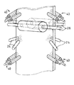
浸漬されたゲルフィルムは、ガイドロールに導かれつつ引き上げられる。図3は、引き上げられた後のゲルフィルムの処理手段を斜視図により表したものである。フィルムにしわや偏りを生じさせないためには、ゲルフィルムは略垂直に引き上げられることが好ましい。
【0053】
次に、ゲルフィルムの両端部に圧縮気体を噴射手段により噴射させる。噴射手段は、フィルムの両端部の表面及び裏面に適用し、具体的には例えばエアノズル24であってもよく、さらに圧縮気体は、窒素、アルゴン等不活性気体または空気であってよい。圧縮気体を噴射することにより、ゲルフィルムの端部に付着した表面処理液を中央部分に寄せる効果を発揮する。エアノズル等噴射手段は、図4(a)正面図に示すようにフィルム表面に対しての角度θが10度以上90度以下の角度、また図4(b)側面図に示すようにフィルム進行方向に対しての角度φが10度以上90度以下の角度に保持されることが好ましい。さらに、噴出した空気がゲルフィルムの端部にあたるように構成されていることが好ましい。具体的には、少なくともゲルフィルムの両端部から30mmのフィルム表面に空気を噴射し得るように位置および空気圧を設定することが好ましい。
【0054】
均一であるポリイミドフィルムを得るために、比較的厚み、乾燥程度の不均一である端部は、表面処理液が残留している場合に切れやすく、また表面処理液除去ロール中を走行させる際に走行筋が発現するおそれがあるため、これを防止するために上記の角度で気体噴射手段を設置することが効果的である。
【0055】
次に、ゲルフィルムは、1対の表面処理液除去ロールであるニップロール26により、フィルム表面に残留する剰余の表面処理液が除去される。ニップロール26は、はっ水性を有し、基本的にゲルフィルムの有機溶媒および表面処理液と反応しない材質であれば特に制限されないが、特にはテフロン製のロールまたは合成樹脂製またはゴム製のロールにテフロンコーティングしたものが好ましい。これらの材質のロールは他の材質に比較して、しわが入りにくくまた表面処理液の液切れが良好である。また、ニップロール26は1対で使用し、ロールツーロール方式でロールの間隙を表面処理液に浸漬されたゲルフィルムが通過する。このロールのニップ圧は、ポリイミドの構造やこれに伴う機械的特性、及び膜厚にもよるが、一般的に、25μmの厚さのフィルムである場合、2〜3kgfのシリンダー圧を付加させることが好ましい。
【0056】
また、この表面処理液の除去ロールであるニップロール26が、ゲルフィルムの両端部から30mmより内側のフィルム表面にあたるように設置されていることが好ましい。フィルム端部は、上記範囲のフィルムと比較して、不均一であるためニップするとフィルム表面にしわがよる原因となり表面処理を行うことが困難であることより、上記範囲のフィルムに接着性付与の処理を施すことが、必要十分であるからである。
【0057】
また、ポリイミドフィルムの構造やこれに伴う機械的特性及び膜厚にもよるが、しわが比較的多い場合、また端部のカールが大きい場合、さらに走行不良の場合等は、ゲルフィルムの端部を支持することが好ましい。具体的には、フィルム端部支持手段として、例えば1対のピンチロール40で支持し得る。図3のピンチロール40は、ゲルフィルムの端部を挟持しつつゲルフィルムの動きに従ってロール部分が可動するように支柱に固定されている構成となっている。このピンチロール40はゲルフィルム両端部を支持し、基本的には複数箇所設置されてもよい。
【0058】
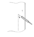
このフィルム端部支持用のピンチロールによりしわのない安定したフィルム幅を得ることができ、さらに端部のカールを矯正し、厚みを一定にすることができる。また、このフィルム端部支持用ピンチロールは、フィルムのしわをなくし走行を潤滑に行うためには、ゲルフィルム両側からフィルム端部を各1対で挟持し、かつ図5に示すように、フィルム進行方向(矢印)に対して10度以上90度以下の角度δに保持されていることが好ましい。
【0059】
このようにして表面処理されたゲルフィルムは、熱処理工程を行うテンター室に供給される。このように、表面処理工程をテンター室での加熱工程の前に設置することにより、表面処理剤の乾燥工程をテンター室の熱処理工程で同時に行うことができる。
【0060】
上記表面処理されたゲルフィルムは端部を固定されテンター室にて加熱処理される。例えば、テンター室は、加熱炉及び徐冷炉で構成され、ピンでフィルムを固定したピンシートをピンコンベアの回転駆動により可動させることにより、フィルムがテンター室内を移動する。熱キュアを行う加熱炉内において徐々に加熱することによりゲルフィルムをさらにイミド化する。加熱炉内では、通常200℃程度の温度から徐々に昇温して、ポリイミドへのイミド化を完了させる。
【0061】
熱処理の温度は、徐々に加熱し最高温度500℃以上620℃以下の温度範囲とすることが好ましい。さらに好ましくは、540℃以上580℃以下の範囲が好ましい。最高温度に達する温度勾配については、上記の温度範囲で熱処理を施せば、特に制限されない。熱処理時間は、数秒〜数十分、好ましくは1分〜5分であり、熱処理温度との関係で適宜設定される。
【0062】
上記熱キュアの工程において、完全にイミド化されたポリイミドフィルムは徐冷炉において徐々に冷却される。
【0063】
本発明にかかる製造方法により得られるポリイミドフィルムは、厚み数μmから数百μmのシート状物を含む広義のフィルムを意味し、用途に応じてその厚みを選択することができる。例えば、フレキシブルプリント配線板のベースフィルム等として使用する場合は12.5μm〜50μm程度のフィルムが適用され得る。
【0064】
本発明にかかる製造方法は、フィルム製造工程中において、表面処理工程を組み込むものであり、具体的には表面処理液の残液処理手段を有する表面処理液への浸漬工程を製造工程中に加えることにより最終製品であるポリイミドフィルムの接着強度の向上に効果的に寄与し得る。
【0065】
以上、本発明にかかるポリイミドフィルムの製造方法の実施の形態の1例を説明したが、本発明はこれら実施の形態のみに限定されず、必要に応じて他の公知の後処理方法、例えば、火炎処理、コロナ処理、紫外線処理、アルカリ処理、プライマ処理、サンドブラスト処理、プラズマ処理等をさらに適用することも可能である等、本発明の趣旨を逸脱しない範囲内で当業者の知識に基づき、種々なる改良、変更、修正を加えた態様で実施し得るものである。
【0066】
【実施例】
以下、本発明にかかるポリイミドフィルムの製造方法について、具体的に実施例を示す。本発明は、これらの実施例に限定されるものではない。
【0067】
なお、実施例において、ポリイミドフィルムに施したコロナ処理は、アルミニウム電極を用いて、電力密度を220±10W・min/m2で処理した。
【0068】
接着強度は以下の方法により測定した。すなわち、得られたポリイミドフィルムにナイロン・エポキシ系接着剤を用いて電解銅箔(三井金属鉱業社製、商品名:3ECVLP、厚み35μm)と張り合わせ3層銅張積層板を作製し、150℃で240時間放置した後の接着強度をJISC−6481に従って銅パターン幅3mm90度ピールで測定した。
【0069】
【実施例1】
芳香族ジアミンとして、4,4’−ジアミノジフェニルエーテルを、芳香族テトラカルボン酸二無水物としてピロメリット酸二無水物を用いて得られたポリアミド酸溶液に、ポリアミド酸の1繰り返し単位当たり分子量に対してイミド化剤として5.5モルの無水酢酸と0.55モルのイソキノリンを添加して十分に攪拌し、約0℃の製膜用ドープ液として調整した。
【0070】
上記得られたドープ液をTダイより、平滑な金属製エンドレスベルト上に連続的に約600μmの厚さで流延塗布し、ベルトを回転させながら熱風乾燥した。この時、ベルト室の温度条件は、ベルト条件120℃×4分、冷却プーリ温度80℃とし、エンドレスベルトから剥がした。このゲルフィルムの残揮発物量は46%であった。
【0071】
ついで、得られたゲルフィルムを0.2wt%のジヒドロキシチタンビスラクテート/ブチルアルコール溶液を充填した表面処理液槽に導入した。浸漬したフィルムを垂直に引き上げ、両端部から50mmまでをエアノズルで圧縮空気を当てることで吹き飛ばして乾燥させ、次にそれより内側を、テフロンコーティングを施したニップロールでニップ圧4kgfでニップし、フィルム各面の残液量を約2g/m2にした。しわ対策としてニップロール前後の両端部にピンチロールを用いた。
【0072】
ついで、これらのフィルムをテンター室で、300℃〜580℃で合計時間約4分の熱処理を行った。その後、冷却室で室温まで徐々に降温し、さらに所定のコロナ処理を行った。得られた50μmのポリイミドフィルムの接着強度を測定したところ、接着強度は1000N/mであった。また塗工ムラは見られず表面状態は良好であった。
【0073】
【比較例1】
実施例1において、ゲルフィルムの浸漬処理工程を行わないこと以外は、同様の処理をして50μmのポリイミドフィルムを得た。接着強度は500N/mであった。
【0074】
【比較例2】
実施例1において、ニップロールを用いない以外は、同様の処理をして50μm のポリイミドフィルムを得た。得られたフィルムは液だれ跡・塗工ムラが多く、またフィルムが黒変しており外観不良であった。
【0075】
【比較例3】
実施例1において、エアノズルを用いない以外は、同様の処理をして50μmのポリイミドフィルムを得た。得られたフィルムはニップロールでニップされている箇所とされていない箇所の境界周辺で液ダレによるスジが発生し外観不良であった。
【0076】
【比較例4】
実施例1において、エアノズルの角度がフィルム進行方向に対して120度の角度で設置する以外は、同様の処理をして50μmのポリイミドフィルムを得た。得られたフィルムは液ダレによるスジが発生し外観不良であった。
【0077】
【発明の効果】
以上のようにして得られたポリイミドフィルムは、表面処理剤による接着性向上を効果的に得ることができ、さらに、ポリイミドフィルムとした後の処理に比較して乾燥工程を、テンター室での熱処理工程の含むことで、工程を省くことができる。
【図面の簡単な説明】
【図1】本発明にかかるポリイミドフィルムの製造装置の模式図である。
【図2】本発明にかかるポリイミドフィルムの製造装置において、表面処理液浸漬工程の、模式図である。
【図3】表面処理液浸漬工程の一部の斜視図である。
【図4】エアノズルの設置方法の正面図(a)及び側面図(b)である。
【図5】ピンチロールの設置方法の正面図である。
【符号の説明】
10;ベルト室
12;Tダイ
14;エンドレスベルト
16、28;ゲルフィルム
18;表面処理液浸漬工程
20;ガイドロール
22;表面処理液槽
24;エアノズル
26;表面処理液除去ロール
30;テンター室
32;ポリイミドフィルム
40;ピンチロール[0001]
BACKGROUND OF THE INVENTION
The present invention relates to a method and an apparatus for producing a polyimide film, and more particularly, to a method and an apparatus for applying a surface treatment liquid to impart adhesion.
[0002]
[Prior art]
Polyimide is known to have excellent properties such as heat resistance, cold resistance, chemical resistance, electrical insulation, and mechanical strength. Electrical insulation film, heat insulation film, flexible printed wiring board base film Widely used. In particular, in applications such as flexible wiring boards and electrical insulation films, specifically, polyimide films are bonded to copper foil via an adhesive to form a trunk laminate, prepreg by adhesive coating, or fluororesin It is often used for applications such as compounding. Therefore, the adhesive ability of the film is an important characteristic, and various improvements in adhesiveness are achieved.
[0003]
By the way, techniques for imparting adhesiveness to a polymer film include, for example, flame treatment, corona treatment, ultraviolet treatment, alkali treatment, sandblast treatment, plasma treatment and the like as post-treatments after film production. In these general techniques, a method is selected that is applied to the polyimide film for the purpose of improving adhesion while maintaining its properties, and various surface treatments using liquids such as coupling agents and alkaline solutions are used to impart adhesion to the polyimide film. It has been.
[0004]
Currently available surface treatments include (i) a method in which a surface treatment agent is mixed into a polyimide precursor solution, and (ii) a method in which a surface treatment agent is applied to the produced polyimide film.
[0005]
Specifically, in the polyimide production process, the above method (i) is obtained by mixing a surface coupling agent in an organic solvent solution of polyamic acid, which is a polyimide precursor, and then casting and heating the polyimide. A method for producing a film. The method (ii) is a method for improving the adhesion of the film by applying a surface treatment agent to a polyimide film produced by casting and heating a polyimide precursor and heating it. .
[0006]
[Problems to be solved by the invention]
However, the method (i) has a problem that a large amount of the surface treatment agent is consumed because the surface treatment agent is required not only on the film surface but also inside the film. Further, the method (ii) has a problem that the effect of improving the adhesion of the surface treatment agent is small because it is difficult for the surface treatment agent to sufficiently penetrate into the completed film.
[0007]
[Means for Solving the Problems]
As a result of intensive studies, the present inventors have developed a method and apparatus for treating a surface treatment agent on a gel film in order to solve the above-mentioned problems and to fully exhibit the effect of improving the adhesive strength of the surface treatment agent. It came to complete.
[0008]
In the first aspect of the present invention, an organic solvent solution containing a polyimide precursor material is casted and then heated to form a gel film.And the step ofImmerse gel film in surface treatment solutionAnd a process ofA step of pulling up the gel film immersed in the surface treatment liquid from the surface treatment liquid;A step of supporting the gel film pulled up by a film end support means, and the gelCompressed gas at the edge of the filmThe step of removing the surface treatment liquid at the end of the gel film, and the gelthe filmofSurfaceThe remainder of the central partRemove surface treatment liquid with removal rollProcess When,Apply heat treatmentProcessThis is a method for producing a polyimide film.
[0009]
The second of the present invention isA method for producing a polyimide film, wherein the gel film immersed in the surface treatment liquid is pulled up substantially vertically from the surface treatment liquidIt is.
[0010]
The third aspect of the present invention isThe film end supporting means is a plurality of film end supporting pinch rolls.It is.
[0011]
The fourth aspect of the present invention isThe removal roll is a nip roll using Teflon (registered trademark), and a method for producing a polyimide filmIt is.
[0012]
The fifth aspect of the present invention isThe method for producing a polyimide film, characterized in that the central portion is in a range inside 30 mm from both ends of the gel film.It is.
[0013]
The sixth of the present invention isThe compressed gas is jetted from an air nozzle, and the air nozzle maintains a gas jetting angle capable of moving the surface treatment liquid on the surface near the end of the gel film in the central direction, and from the film outer side to the film central direction. A method for producing a polyimide film characterized by being set as a pair towardIt is.
[0014]
The seventh of the present invention isThe air nozzle is held at an angle of not less than 10 degrees and not more than 90 degrees with respect to the film width direction and at an angle of not less than 10 degrees and not more than 90 degrees with respect to the film traveling direction, and the injected compressed gas is an end of the gel film A method for producing a polyimide film, characterized in thatIt is.
[0015]
The eighth of the present invention isThe said edge part is the range of 30 mm from the both ends of the said gel film, The manufacturing method of the polyimide film characterized by the above-mentionedIt is.
[0016]
9th of this invention is the said film edge part support pinch roll,SaidGel filmofInstalled at both endsThe filmProduction of a polyimide film characterized in that the film ends are sandwiched in pairs from the front and back surfaces and held at an angle of 10 degrees to 90 degrees with respect to the film traveling direction.MethodIt is.
[0017]
The tenth aspect of the present invention isThe surface treatment liquid is stored, the gel film formed by casting and heating the organic solvent solution containing the polyimide precursor material is immersed therein, and the surface treatment liquid tank is immersed in the surface treatment liquid A guide roll for pulling up the gel film, a film end supporting means for supporting the pulled gel film, an air nozzle for injecting compressed gas to the end of the gel film supported by the film end supporting means, and the gel An apparatus for producing a polyimide film, comprising: a removing roll that removes the surplus surface treatment liquid at the center of the surface of the film; and a tenter chamber that heat-treats the gel film from which the surplus surface treatment liquid has been removed.It is.
[0018]
The eleventh aspect of the present invention isAn apparatus for producing a polyimide film, wherein a gel film immersed in the surface treatment liquid is pulled up substantially vertically from the surface treatment liquid through the guide rollIt is.
[0019]
The twelfth aspect of the present invention isThe film end support means is a plurality of film end support pinch rolls.It is.
[0020]
DETAILED DESCRIPTION OF THE INVENTION
Hereinafter, although the manufacturing method of the polyimide film concerning this invention and its apparatus are demonstrated based on one example of embodiment, this invention is not limited to these.
[0021]
In general, since a polyimide film is insoluble and infusible, a solvent cast method in which an organic solvent solution of the precursor material is cast on a support such as a drum or a belt is used. In the method for producing a polyimide film according to the present invention, Also use this method.
[0022]
Hereafter, the manufacturing method and apparatus of the polyimide film concerning this invention are demonstrated concretely.
[0023]
The polyimide film according to the present invention is obtained from various known raw materials and is not particularly limited. Mainly using organic tetracarboxylic dianhydride and organic diamine as raw materials, each component is substantially used. It is obtained by polymerization in an organic solvent solution using equimolar amounts.
[0024]
The polyimide film according to the present invention is a film made of polyimide in a broad sense, and examples thereof include polyimide, polyamideimide, polyetherimide, and polyesterimide, and are not particularly limited such as non-thermoplastic, thermoplastic, and thermosetting. . That is, the molecular structure of polyimide does not matter. For example, preferably, the following general structural formula (1)
[Chemical 1]
[0025]
Where R1Is a tetravalent organic group, specifically, has at least one aromatic group, and has an aromatic ring directly bonded to an adjacent carbonyl group to be bonded. More specifically,
[Chemical 2]
[Chemical 3]
[0026]
In the formula, R2Has a divalent organic group, specifically at least one aromatic,
More specifically,
[Formula 4]
[0027]
Particularly preferred polyimides are those in which R1However,
[Chemical formula 5]
[Chemical 6]
[Chemical 7]
[Chemical 8]
[Chemical 9]
[0028]
More preferably,
[Chemical Formula 10]
Embedded image
[Expression 1]
Embedded image
Embedded image
Embedded image
Embedded image
Embedded image
Embedded image
[0029]
Hereinafter, the manufacturing method of a polyimide resin is demonstrated. The polyimide resin represented by the general formula (1) is obtained by dehydrating and ring-closing the precursor polyamic acid polymer, and this polyamic acid solution is prepared by a conventionally known method using acid dianhydride and diamine. It is obtained by polymerizing in an organic polar solvent using substantially equimolar amounts of the components.
[0030]
First, a method for producing a polyamic acid will be described. First, in an inert gas atmosphere such as argon or nitrogen, the general formula (2)
Embedded image
H2N-R2-NH2 (3)
(Wherein R2Represents a divalent organic group. And at least one diamine component dissolved in an organic solvent or dispersed in a slurry state or in a solid state to obtain a polyamic acid polymer solution.
[0031]
The reaction temperature at this time is preferably -10 ° C to 50 ° C. The reaction time is about 30 minutes to 6 hours.
[0032]
In this reaction, contrary to the above addition order, first, the diamine component may be diffused or dissolved, and a solution or slurry of acid dianhydride solid or organic solvent may be added to the solution.
[0033]
In order to maintain the strength of the produced polyimide resin, the number average molecular weight is preferably 10,000 or more. The molecular weight of a polyimide polymer is often difficult to measure directly. In such a case, estimation is performed by an indirect method. For example, when the polyimide polymer is synthesized from polyamic acid, the value corresponding to the molecular weight of the polyamic acid is taken as the molecular weight of the polyimide.
[0034]
Further, the general formula (2)
Embedded image
Embedded image
Embedded image
[0035]
As the diamine compound represented by the general formula (3), various diamines can be used essentially. More specifically, from the balance of various properties, the general formula (3)
H2N-R2-NH2 (3)
R inside2However,
Embedded image
[0036]
Furthermore, examples of the organic solvent that can be used in the present invention include sulfoxide solvents such as dimethyl sulfoxide and diethyl sulfoxide, formamide solvents such as N, N-dimethylformamide and N, N-diethylformamide, and N, N-dimethyl. Acetamide solvents such as acetamide and N, N-diethylacetamide, pyrrolidone solvents such as N-methyl-2-pyrrolidone and N-vinyl-2-pyrrolidone, phenol, o-, m-, or p-cresol, xylenol, Phenolic solvents such as halogenated phenols and catechols, hexamethylphosphoramide, γ-butyrolactone, etc. can be mentioned, and these are preferably used alone or as a mixture, but more preferably aromatic such as xylene and toluene. Some hydrocarbons Use is also possible.
[0037]
In addition, when preparing the polyamic acid solution, or after preparing the polyamic acid solution, or as a dehydrating agent and catalyst by a chemical method, an antioxidant, a light stabilizer, a flame retardant, an antistatic agent, a heat stabilizer, UV absorption An agent, inorganic fillers, other reinforcing agents, or the like can be mixed.
[0038]
In addition, a method for producing polyimide is a chemical in which a polyamic acid which is a precursor is reacted with a dehydrating ring-closing agent represented by an acid anhydride such as acetic anhydride and a tertiary amine such as picoline, quinoline, isoquinoline or pyridine. A method of converting to polyimide by a curing method and a so-called thermal curing method in which an imidization reaction proceeds only by heating without causing the dehydrating agent or the like to act can also be used. Furthermore, a method using both in combination can also be used.
[0039]
When the chemical curing method and the thermal curing method are combined, usually the chemical curing method is mainly performed in the first half of the process, and then the imidization is completed by the thermal curing method in the second half.
[0040]
Here, the “gel film” in the present invention is defined as a film at the stage where the first chemical curing process is completed, or a film before entering the thermal curing process by the thermal curing method.
[0041]
The production method for imidizing the polyimide precursor and finally making the polyimide film product is divided into a drum chamber or belt chamber equipped with a heating means for casting and chemical curing, and a tenter chamber for performing thermal curing. It is done.
[0042]
FIG. 1 shows an example of a production process of a polyimide film according to the present invention. First, the process in the
[0043]
Heating means adjusts the ambient temperature and the rotation speed of the belt or drum in order to prevent the risk of ignition of flammable volatile components evaporated from the resin or to prevent the resin itself from igniting. For example, heating with warm air, hot air, radiant heat, belt heating, or the like can be used.
[0044]
Through these steps, while the polyimide precursor film is imidized, the film is heated and dried to the extent that the film has self-supporting properties, and then peeled off from the endless belt or casting drum to obtain the
[0045]
By the way, in the case of performing imidization while transporting a normal film through the above process, the shape and surface state of the gel film are best maintained, and the difficulty on the surface such as peeling and wrinkling of the film is prevented, and the film has self-supporting property. The amount of residual volatiles is measured as an index for producing a film without problems in transportation and processing.
[0046]
In the present invention, the amount of residual volatiles in the film is expressed by the following formula:
[Expression 2]
W0: Weight after heat treatment at 450 ° C. for 20 minutes
[0047]
Usually, the amount of residual volatiles peeled off from a support such as an endless belt or drum is in the range of 20 to 200% by weight. If the amount of residual volatiles exceeds 200% by weight, problems such as difficulty in peeling from the belt or drum and poor self-supporting property of the film after peeling occur. On the other hand, if the amount of residual volatiles is less than 20% by weight, the gel film is peeled off from the support and lifted from the belt or drum before the film peeling step, and the conveyance becomes unstable and vice versa. This is because there arises a problem that the film may be difficult to peel off from the support.
[0048]
The gel film obtained as described above undergoes the surface treatment
[0049]
FIG. 2 is a schematic diagram showing a surface treatment liquid immersion step in the polyimide film manufacturing apparatus according to the present invention. The arrow indicates the traveling direction of the gel film. The gel film having passed through the belt chamber is immersed in the surface
Embedded image
[0050]
The above coupling agent is dissolved in a solvent and used as a solution. Examples of this solution include alcohol solvents such as methanol, ethanol, propanol, isopropanol, or Solmix which is a mixed solvent thereof, acetone, MEK, 2- Examples thereof include ketone solvents such as pentanone and 3-pentanone, and aromatic hydrocarbon solvents such as toluene and xylene. These may be used alone or in combination of several kinds.
[0051]
The concentration of the coupling agent solution is preferably 0.005 wt% to 30 wt%, and particularly preferably 0.01 wt% to 5 wt%. When the concentration of the coupling agent is too high, unevenness is seen on the surface of the polyimide film, and the color of the film becomes dark, which is not preferable in appearance. On the other hand, if the concentration of the coupling agent is too low, sufficient effects are not exhibited.
[0052]
The immersed gel film is pulled up while being guided to the guide roll. FIG. 3 is a perspective view showing the gel film processing means after being pulled up. In order not to cause wrinkles or bias in the film, the gel film is preferably pulled up substantially vertically.
[0053]
Next, compressed gas is sprayed to both ends of the gel film by spraying means. The spraying means is applied to the front and back surfaces of both end portions of the film. Specifically, for example, the
[0054]
In order to obtain a uniform polyimide film, the edge that is relatively non-uniform in thickness and dryness is easily cut when the surface treatment liquid remains, and when traveling in the surface treatment liquid removal roll Since running muscles may develop, it is effective to install the gas injection means at the above angle in order to prevent this.
[0055]
Next, the surplus surface treatment liquid remaining on the film surface is removed from the gel film by a
[0056]
Moreover, it is preferable that the
[0057]
Also, depending on the structure of the polyimide film and the mechanical properties and film thickness associated therewith, if the wrinkles are relatively large, if the curl at the end is large, or if the run is poor, the end of the gel film Is preferably supported. Specifically, for example, a pair of pinch rolls 40 can support the film end support means. The pinch roll 40 in FIG. 3 is configured to be fixed to the support so that the roll portion moves according to the movement of the gel film while sandwiching the end portion of the gel film. The
[0058]
A stable film width free of wrinkles can be obtained by this pinch roll for supporting the film end, and curling of the end can be corrected to make the thickness constant. Also, this pinch roll for supporting the film end portion is provided with a pair of film end portions sandwiched from both sides of the gel film in order to eliminate wrinkling of the film and lubricate running, and as shown in FIG. It is preferable that the angle δ is 10 degrees or more and 90 degrees or less with respect to the traveling direction (arrow).
[0059]
The gel film surface-treated in this way is supplied to a tenter chamber that performs a heat treatment step. Thus, by installing the surface treatment step before the heating step in the tenter chamber, the surface treatment agent drying step can be simultaneously performed in the heat treatment step of the tenter chamber.
[0060]
The surface-treated gel film is fixed at the end and heat-treated in the tenter chamber. For example, the tenter chamber is composed of a heating furnace and a slow cooling furnace, and the film moves in the tenter chamber by moving a pin sheet having a film fixed with pins by rotational driving of a pin conveyor. The gel film is further imidized by gradually heating in a heating furnace for performing heat curing. In the heating furnace, the temperature is gradually raised from about 200 ° C. to complete imidation into polyimide.
[0061]
It is preferable that the temperature of the heat treatment is gradually increased to a maximum temperature range of 500 ° C. to 620 ° C. More preferably, a range of 540 ° C. or higher and 580 ° C. or lower is preferable. The temperature gradient reaching the maximum temperature is not particularly limited as long as the heat treatment is performed in the above temperature range. The heat treatment time is several seconds to several tens of minutes, preferably 1 minute to 5 minutes, and is appropriately set in relation to the heat treatment temperature.
[0062]
In the thermal curing step, the completely imidized polyimide film is gradually cooled in a slow cooling furnace.
[0063]
The polyimide film obtained by the production method according to the present invention means a broad film including a sheet-like material having a thickness of several μm to several hundred μm, and the thickness can be selected according to the application. For example, when using as a base film of a flexible printed wiring board, a film of about 12.5 μm to 50 μm can be applied.
[0064]
The production method according to the present invention incorporates a surface treatment process in the film production process, and specifically, an immersion process in the surface treatment liquid having means for treating the residual liquid of the surface treatment liquid is added during the production process. This can effectively contribute to the improvement of the adhesive strength of the polyimide film as the final product.
[0065]
As mentioned above, although one example of embodiment of the manufacturing method of the polyimide film concerning the present invention was explained, the present invention is not limited only to these embodiments, and other known post-treatment methods as needed, for example, Based on the knowledge of those skilled in the art, flame treatment, corona treatment, ultraviolet treatment, alkali treatment, primer treatment, sandblast treatment, plasma treatment, etc. can be further applied, and the like within the scope of the present invention. The present invention can be carried out in a mode with improvements, changes and modifications.
[0066]
【Example】
Hereinafter, an Example is shown concretely about the manufacturing method of the polyimide film concerning this invention. The present invention is not limited to these examples.
[0067]
In the examples, the corona treatment applied to the polyimide film uses an aluminum electrode and the power density is 220 ± 10 W · min / m.2Was processed.
[0068]
The adhesive strength was measured by the following method. That is, a three-layer copper-clad laminate was prepared by laminating the obtained polyimide film with an electrolytic copper foil (product name: 3ECVLP, thickness 35 μm) using a nylon / epoxy adhesive at 150 ° C. The adhesive strength after standing for 240 hours was measured at a copper pattern width of 3 mm and a 90 degree peel in accordance with JISC-6481.
[0069]
[Example 1]
To the polyamic acid solution obtained by using 4,4′-diaminodiphenyl ether as the aromatic diamine and pyromellitic dianhydride as the aromatic tetracarboxylic dianhydride, the molecular weight per repeating unit of the polyamic acid is Then, 5.5 moles of acetic anhydride and 0.55 moles of isoquinoline were added as imidizing agents and stirred sufficiently to prepare a dope solution for film formation at about 0 ° C.
[0070]
The obtained dope solution was continuously cast from a T die on a smooth metal endless belt at a thickness of about 600 μm, and dried with hot air while rotating the belt. At this time, the temperature conditions of the belt chamber were a belt condition of 120 ° C. × 4 minutes and a cooling pulley temperature of 80 ° C., and the belt chamber was peeled off from the endless belt. The residual volatile content of this gel film was 46%.
[0071]
Next, the obtained gel film was introduced into a surface treatment bath filled with 0.2 wt% dihydroxytitanium bislactate / butyl alcohol solution. The soaked film is pulled up vertically and blown off by applying compressed air with air nozzles up to 50 mm from both ends. The amount of liquid remaining on the surface is about 2 g / m2I made it. As a countermeasure against wrinkles, pinch rolls were used at both ends before and after the nip roll.
[0072]
Subsequently, these films were heat-treated in a tenter chamber at 300 ° C. to 580 ° C. for a total time of about 4 minutes. Thereafter, the temperature was gradually lowered to room temperature in the cooling chamber, and a predetermined corona treatment was further performed. When the adhesive strength of the obtained polyimide film of 50 μm was measured, the adhesive strength was 1000 N / m. Further, no coating unevenness was observed, and the surface condition was good.
[0073]
[Comparative Example 1]
In Example 1, except having not performed the immersion treatment process of a gel film, the same process was performed and the polyimide film of 50 micrometers was obtained. The adhesive strength was 500 N / m.
[0074]
[Comparative Example 2]
In Example 1, a 50 μm polyimide film was obtained in the same manner except that no nip roll was used. The obtained film had many dripping traces and coating unevenness, and the film was black and had a poor appearance.
[0075]
[Comparative Example 3]
In Example 1, a 50 μm polyimide film was obtained by performing the same treatment except that no air nozzle was used. The resulting film had a poor appearance due to the occurrence of streaks due to liquid dripping around the boundary between the portion that was nipped by the nip roll and the portion that was not.
[0076]
[Comparative Example 4]
In Example 1, a 50 μm polyimide film was obtained by performing the same treatment except that the air nozzle was installed at an angle of 120 degrees with respect to the film traveling direction. The resulting film had poor appearance due to the occurrence of streaks due to dripping.
[0077]
【The invention's effect】
The polyimide film obtained as described above can effectively improve the adhesion due to the surface treatment agent, and further, the drying process is compared with the treatment after the polyimide film, and the heat treatment in the tenter chamber By including the process, the process can be omitted.
[Brief description of the drawings]
FIG. 1 is a schematic view of a polyimide film manufacturing apparatus according to the present invention.
FIG. 2 is a schematic view of a surface treatment liquid immersion step in the polyimide film manufacturing apparatus according to the present invention.
FIG. 3 is a partial perspective view of a surface treatment liquid immersion step.
FIGS. 4A and 4B are a front view and a side view of an air nozzle installation method. FIGS.
FIG. 5 is a front view of a pinch roll installation method.
[Explanation of symbols]
10; belt chamber
12; T-die
14; Endless belt
16, 28; gel film
18; surface treatment liquid immersion step
20; guide roll
22; surface treatment bath
24; Air nozzle
26; surface treatment liquid removing roll
30; Tenter room
32; Polyimide film
40; pinch roll
Claims (11)
前記ゲルフィルムを表面処理液に浸漬する工程と、
前記表面処理液に浸漬されたゲルフィルムを該表面処理液から引き上げる工程と、
引き上げられた前記ゲルフィルムをフィルム端部支持手段により支持する工程と、
前記ゲルフィルムの端部に圧縮気体をあてて、該ゲルフィルムの端部の前記表面処理液を除去する工程と、
前記ゲルフィルムの表面の中央部分の剰余の前記表面処理液を除去ロールにより除去する工程と、
さらに熱処理を施す工程と
を含むことを特徴とするポリイミドフィルムの製造方法。A step of casting an organic solvent solution containing a polyimide precursor material and then heating to form a gel film;
Immersing the gel film in a surface treatment liquid;
A step of pulling up the gel film immersed in the surface treatment liquid from the surface treatment liquid;
A step of supporting the gel film pulled up by a film end support means;
Applying a compressed gas to the end of the gel film to remove the surface treatment liquid at the end of the gel film;
Removing the surplus surface treatment liquid at the center of the surface of the gel film with a removing roll;
Furthermore, the process of performing heat processing is included, The manufacturing method of the polyimide film characterized by the above-mentioned.
前記表面処理液に浸漬されたゲルフィルムを引き上げるガイドロールと、
引き上げられた前記ゲルフィルムを支持するフィルム端部支持手段と、
前記フィルム端部支持手段で支持されたゲルフィルムの端部に圧縮気体を噴射するエアノズルと、
前記ゲルフィルムの表面の中央部分の剰余の前記表面処理液を除去する除去ロールと、
前記剰余の表面処理液が除去されたゲルフィルムに熱処理を施すテンター室と
を備えるポリイミドフィルムの製造装置。Surface treatment liquid is stored, surface treatment liquid tank in which a gel film formed by casting and heating an organic solvent solution containing a polyimide precursor material is immersed, and
A guide roll for pulling up the gel film immersed in the surface treatment liquid;
Film end support means for supporting the gel film pulled up;
An air nozzle for injecting compressed gas to the end of the gel film supported by the film end support means;
A removal roll for removing the surplus surface treatment liquid at the center of the surface of the gel film;
An apparatus for producing a polyimide film, comprising: a tenter chamber for heat-treating the gel film from which the surplus surface treatment liquid has been removed.
Priority Applications (1)
| Application Number | Priority Date | Filing Date | Title |
|---|---|---|---|
| JP344399A JP3973311B2 (en) | 1999-01-08 | 1999-01-08 | Method and apparatus for producing polyimide film |
Applications Claiming Priority (1)
| Application Number | Priority Date | Filing Date | Title |
|---|---|---|---|
| JP344399A JP3973311B2 (en) | 1999-01-08 | 1999-01-08 | Method and apparatus for producing polyimide film |
Publications (2)
| Publication Number | Publication Date |
|---|---|
| JP2000204178A JP2000204178A (en) | 2000-07-25 |
| JP3973311B2 true JP3973311B2 (en) | 2007-09-12 |
Family
ID=11557503
Family Applications (1)
| Application Number | Title | Priority Date | Filing Date |
|---|---|---|---|
| JP344399A Expired - Fee Related JP3973311B2 (en) | 1999-01-08 | 1999-01-08 | Method and apparatus for producing polyimide film |
Country Status (1)
| Country | Link |
|---|---|
| JP (1) | JP3973311B2 (en) |
Families Citing this family (11)
| Publication number | Priority date | Publication date | Assignee | Title |
|---|---|---|---|---|
| JP4522560B2 (en) * | 2000-08-31 | 2010-08-11 | エルナー株式会社 | Multilayer wiring board and manufacturing method thereof |
| WO2002068512A1 (en) | 2001-02-27 | 2002-09-06 | Kaneka Corporation | Polyimide film and process for producing the same |
| JP4504650B2 (en) * | 2002-09-19 | 2010-07-14 | 富士フイルム株式会社 | Solution casting method |
| KR100967326B1 (en) * | 2005-04-07 | 2010-07-05 | 우베 고산 가부시키가이샤 | Method for producing polyimide film and polyimide film |
| US9352498B2 (en) | 2009-10-09 | 2016-05-31 | Ube Industries, Ltd. | Method of manufacturing polyimide film and tenter apparatus |
| CN102741330B (en) * | 2009-12-09 | 2014-07-02 | 宇部兴产株式会社 | Method for preparing polyimide film and polyimide film |
| JP5969180B2 (en) * | 2011-08-02 | 2016-08-17 | 日東電工株式会社 | Processed film manufacturing method and apparatus |
| JP5592463B2 (en) * | 2012-11-30 | 2014-09-17 | 株式会社カネカ | Isotropic adhesive film, method for producing the same, and flexible metal laminate using the adhesive film |
| CN105128058A (en) * | 2015-09-30 | 2015-12-09 | 杭州育福龙医疗器械有限公司 | Full-automatic hobbing cutter type coating slicing machine |
| CN108327377B (en) * | 2018-03-13 | 2023-05-23 | 广西师范大学 | A preparation device for polyimide film or polyimide copper clad laminate |
| CN118543515B (en) * | 2024-05-23 | 2025-11-04 | 济南大学 | A method for directly preparing polyimide insulating films on aluminum plates |
-
1999
- 1999-01-08 JP JP344399A patent/JP3973311B2/en not_active Expired - Fee Related
Also Published As
| Publication number | Publication date |
|---|---|
| JP2000204178A (en) | 2000-07-25 |
Similar Documents
| Publication | Publication Date | Title |
|---|---|---|
| JP5613300B2 (en) | Novel polyimide film, adhesive film obtained using the same, and flexible metal-clad laminate | |
| JP3973311B2 (en) | Method and apparatus for producing polyimide film | |
| US8298366B2 (en) | Adhesive sheet and copper-clad laminate | |
| JPS59162044A (en) | Thick polyimide-metal laminate of large exfoliation strength | |
| JP3729315B2 (en) | Manufacturing method and manufacturing apparatus for polyimide film | |
| KR102736956B1 (en) | Polyimide film | |
| US20100003531A1 (en) | Novel polyimide film with improved adhesiveness | |
| JP5049594B2 (en) | Novel polyimide film with improved adhesion | |
| JP4078625B2 (en) | Biaxially oriented polyimide film and method for producing the same | |
| JPWO2006115258A1 (en) | Novel polyimide film and its use | |
| JP4006779B2 (en) | Method for producing polyimide film | |
| JP2016183224A (en) | Polyimide film and method for producing the same | |
| JP2002321235A (en) | Polyimide film manufacturing equipment | |
| CN107880546A (en) | Polyimide film | |
| JP2004083885A (en) | Polyamic acid mixture, polyimide, polyimide film and use of the same | |
| JP2005194318A (en) | Polyimide film | |
| JP2002234040A (en) | Polyimide film, its production method and use | |
| KR20080044330A (en) | Heat resistant adhesive sheet | |
| JP2007169494A (en) | Aromatic polyimide film, coverlay film and flexible laminate | |
| JP4490593B2 (en) | Method for producing polyimide film | |
| JP4977953B2 (en) | Polyimide precursor film, method for producing polyimide film, and polyimide film | |
| JP4074987B2 (en) | Polyimide film and stiffener for flexible circuit board using the same | |
| CN101232996B (en) | Flexible Metal Clad Laminates | |
| KR20060123524A (en) | Manufacturing method of synthetic resin film whose orientation of molecules was controlled in MD direction | |
| JP6280389B2 (en) | Method for producing polyimide film |
Legal Events
| Date | Code | Title | Description |
|---|---|---|---|
| A521 | Written amendment |
Free format text: JAPANESE INTERMEDIATE CODE: A523 Effective date: 19990510 |
|
| A621 | Written request for application examination |
Free format text: JAPANESE INTERMEDIATE CODE: A621 Effective date: 20040127 |
|
| A977 | Report on retrieval |
Free format text: JAPANESE INTERMEDIATE CODE: A971007 Effective date: 20050906 |
|
| A131 | Notification of reasons for refusal |
Free format text: JAPANESE INTERMEDIATE CODE: A131 Effective date: 20051011 |
|
| A521 | Written amendment |
Free format text: JAPANESE INTERMEDIATE CODE: A523 Effective date: 20051212 |
|
| A521 | Written amendment |
Free format text: JAPANESE INTERMEDIATE CODE: A523 Effective date: 20051212 |
|
| A131 | Notification of reasons for refusal |
Free format text: JAPANESE INTERMEDIATE CODE: A131 Effective date: 20060530 |
|
| A521 | Written amendment |
Free format text: JAPANESE INTERMEDIATE CODE: A523 Effective date: 20060728 |
|
| A02 | Decision of refusal |
Free format text: JAPANESE INTERMEDIATE CODE: A02 Effective date: 20061114 |
|
| A521 | Written amendment |
Free format text: JAPANESE INTERMEDIATE CODE: A523 Effective date: 20061215 |
|
| A911 | Transfer of reconsideration by examiner before appeal (zenchi) |
Free format text: JAPANESE INTERMEDIATE CODE: A911 Effective date: 20070122 |
|
| A01 | Written decision to grant a patent or to grant a registration (utility model) |
Free format text: JAPANESE INTERMEDIATE CODE: A01 Effective date: 20070403 |
|
| R155 | Notification before disposition of declining of application |
Free format text: JAPANESE INTERMEDIATE CODE: R155 |
|
| A61 | First payment of annual fees (during grant procedure) |
Free format text: JAPANESE INTERMEDIATE CODE: A61 Effective date: 20070612 |
|
| R150 | Certificate of patent or registration of utility model |
Free format text: JAPANESE INTERMEDIATE CODE: R150 |
|
| FPAY | Renewal fee payment (event date is renewal date of database) |
Free format text: PAYMENT UNTIL: 20100622 Year of fee payment: 3 |
|
| LAPS | Cancellation because of no payment of annual fees |