JP3966267B2 - Substrate rubbing method and rubbing apparatus - Google Patents
Substrate rubbing method and rubbing apparatus Download PDFInfo
- Publication number
- JP3966267B2 JP3966267B2 JP2003350798A JP2003350798A JP3966267B2 JP 3966267 B2 JP3966267 B2 JP 3966267B2 JP 2003350798 A JP2003350798 A JP 2003350798A JP 2003350798 A JP2003350798 A JP 2003350798A JP 3966267 B2 JP3966267 B2 JP 3966267B2
- Authority
- JP
- Japan
- Prior art keywords
- rubbing
- substrate
- suction
- dust
- suction port
- Prior art date
- Legal status (The legal status is an assumption and is not a legal conclusion. Google has not performed a legal analysis and makes no representation as to the accuracy of the status listed.)
- Expired - Fee Related
Links
Images


Description
本発明は基板のラビング方法及びラビング装置に係り、特に、液晶電気光学素子を形成するための基板の表面にラビング処理を施す場合の方法及び装置に関する。 The present invention relates to a substrate rubbing method and a rubbing apparatus, and more particularly to a method and an apparatus for rubbing a surface of a substrate for forming a liquid crystal electro-optic element.
液晶電気光学素子は、液晶表示装置等の種々の応用分野において盛んに使用されているものであるが、多くの場合、2枚の基板の間に液晶を挟み込み、この液晶の光学状態を電気的に制御する構造となっている。ここで、基板の表面には、液晶と接触した際に液晶分子が所定の方向に整列して指向性を発揮するように制御するためのラビング処理が施される場合がある。 Liquid crystal electro-optical elements are actively used in various application fields such as liquid crystal display devices. In many cases, liquid crystal is sandwiched between two substrates, and the optical state of the liquid crystal is electrically changed. It has a structure to control to. Here, the surface of the substrate may be subjected to a rubbing process for controlling so that liquid crystal molecules are aligned in a predetermined direction and exhibit directivity when in contact with the liquid crystal.
ラビング処理は、通常、基板上にポリイミド、ポリビニルアルコール等の配向膜を形成し、この配向膜の表面を布等によって所定の方向に擦ることにより行われる。擦られた配向膜の表面には多数の微細な傷が所定の方向に伸びるように形成され、この傷の伸びる方向に液晶分子が配向する。 The rubbing treatment is usually performed by forming an alignment film such as polyimide or polyvinyl alcohol on a substrate and rubbing the surface of the alignment film with a cloth or the like in a predetermined direction. On the surface of the rubbed alignment film, a large number of fine scratches are formed so as to extend in a predetermined direction, and the liquid crystal molecules are aligned in the extending direction of the scratches.
図15は、上記ラビング処理を行うための装置の概略図である。この図に示すように、ラビング装置には、予め基板を導入する導入面10が設けられ、この導入面10に沿って複数の搬送ローラ11が並列されている。搬送ローラ11は、図示しない駆動手段によってそれぞれ基板20を図示右側に搬送するように回転駆動される。
FIG. 15 is a schematic view of an apparatus for performing the rubbing process. As shown in this figure, the rubbing apparatus is provided with an
導入面10の上方にはラビングローラ21が軸支されており、このラビングローラ21は図示しない駆動手段によって図示時計周りに回転するようになっている。ラビングローラ21の周面上にはクロス材22が貼り付けられている。このクロス材22はナイロンやレーヨン等の繊維によって織られたものであり、表面に多数の微少な毛足部が密生している。
A
ラビング処理は、表面に配向膜を形成したガラス基板等からなる基板20を搬送ローラ11によって図示左側から右側へと搬送し、ラビングローラ21の周面上に貼着されたクロス材22によって配向膜を擦ることによって行われる。ラビングローラ21は、図示しない圧力付与機構によって基板20に対して所定の圧力で押し付けられながら、基板20の表面を擦っていく。
In the rubbing treatment, a
ところで、上記のようにラビング処理を行うと、基板20の表面からは、クロス材22で擦られることによって配向膜が削れて細かな粉塵が発生するととともに、クロス材22の表面からは該クロス材22の削れによるパーティクル等の細かな粉塵が発生し、これらの粉塵はクロス材22の表面上に付着するとともに、基板20の表面上にも付着する。粉塵のクロス材22への付着はその後におけるラビング処理においてラビング状態に影響を与え、粉塵の基板20への付着は基板20の表面状態に影響を与えるため、いずれも液晶表示装置等の表示品位を劣化させる原因となる。
By the way, when the rubbing treatment is performed as described above, the alignment film is scraped from the surface of the
基板20に付着した粉塵の除去は、ラビング工程の後の洗浄工程において行われるが、洗浄によって粉塵を完全に除去することは困難であり、また、クロス材22への粉塵の付着によってラビング状態に影響が生じた場合には、洗浄によっては回復させることができない。
The dust attached to the
また、一般的に液晶表示装置の製造工程ではきわめて精密なクリーン度の管理が必要であり、上記ラビング処理においては、ラビング装置内及び装置の周辺にも粉塵が分散されることとなるため、その他の製造工程に対してクリーン度の低下による影響を与えないように、ラビング工程及洗浄工程をその他の製造工程とは仕切られた特別な環境で行わなければならないという問題点がある。 In addition, in general, the manufacturing process of a liquid crystal display device requires a very precise control of cleanliness. In the rubbing process, dust is dispersed in and around the rubbing device. Therefore, there is a problem that the rubbing process and the cleaning process must be performed in a special environment separated from the other manufacturing processes so that the manufacturing process is not affected by the decrease in cleanness.
本発明はかかる問題点を解決するためになされたものであり、ラビング処理によって発生する粉塵に起因する種々の影響を防止し、高品位の液晶電気光学素子を容易に製造することができる基板のラビング方法及び装置を提供することを目的とする。 The present invention has been made to solve such a problem, and prevents various influences caused by dust generated by rubbing treatment and can easily manufacture a high-quality liquid crystal electro-optical element. An object is to provide a rubbing method and apparatus.
かかる目的を達成するために、本発明に係る基板のラビング方法は、液晶電気光学素子に使用する基板をラビング処理部材によって擦るようにした基板のラビング方法において、前記基板と前記ラビング処理部材との接触部に向かって開口した吸引口を有する吸引部材を備える吸引手段と、前記接触部に向かって開口した吹付口を有する吹付手段とを用いて、前記基板と前記ラビング処理部材との少なくとも一方から発生する粉塵を吸引しながらラビング処理を行う工程を有し、前記ラビング処理を行う工程において、吹付口から、前記ラビング処理部材又は前記基板に対して流体を吹き付けることを特徴とする。
本発明に係る基板のラビング方法は、前記流体は、イオン化されたエアであることを特徴とする。
本発明に係る基板のラビング方法は、前記流体は、純水であることを特徴とする。
本発明に係る基板のラビング方法は、液晶電気光学素子に使用する基板の表面をラビング処理部材によって擦るようにした基板のラビング方法において、前記基板と前記ラビング処理部材の少なくとも一方から発生する粉塵を吸引しながらラビング処理を行うことを特徴とする。
In order to achieve this object, a substrate rubbing method according to the present invention is a substrate rubbing method in which a substrate used in a liquid crystal electro-optical element is rubbed with a rubbing treatment member. From at least one of the substrate and the rubbing treatment member using a suction unit including a suction member having a suction port opened toward the contact portion and a spraying unit having a spray port opened toward the contact portion. It has a step of performing a rubbing process while sucking generated dust, and in the step of performing the rubbing process, a fluid is sprayed from the spray port to the rubbing processing member or the substrate.
The substrate rubbing method according to the present invention is characterized in that the fluid is ionized air.
The substrate rubbing method according to the present invention is characterized in that the fluid is pure water.
The substrate rubbing method according to the present invention is a substrate rubbing method in which the surface of a substrate used in a liquid crystal electro-optical element is rubbed with a rubbing treatment member, and dust generated from at least one of the substrate and the rubbing treatment member is removed. A rubbing process is performed while sucking.
この手段によれば、基板表面をラビング処理部材で擦った際に発生する粉塵を吸引するようにしているので、粉塵が基板表面に堆積したり、ラビング処理部材に付着したりすることが抑制され、液晶電気光学素子の表示品位を高めることができる。 According to this means, dust generated when the substrate surface is rubbed with a rubbing treatment member is sucked, so that dust is prevented from being deposited on the substrate surface or adhering to the rubbing treatment member. The display quality of the liquid crystal electro-optical element can be improved.
本発明に係る基板のラビング方法は、上記本発明において、前記吸引を前記粉塵の発生部において行うことを特徴とする。 The substrate rubbing method according to the present invention is characterized in that, in the present invention, the suction is performed in the dust generation part.
この手段によれば、粉塵の吸引を該粉塵の発生部において行うようにしたので、粉塵が周囲環境に撒き散らされることがなく、製造工程におけるクリーン度の管理も容易になる。 According to this means, since the dust is sucked in the dust generating part, the dust is not scattered in the surrounding environment, and the cleanliness management in the manufacturing process is facilitated.
本発明に係る基板のラビング装置は、液晶電気光学素子に用いる基板を擦るためのラビング処理部材と、前記基板と前記ラビング処理部材とを相対的に動作させて前記基板を前記ラビング処理部材によって擦るように駆動する駆動手段と、前記基板と前記ラビングローラとの接触部に向かって開口した吸引口を有し、前記基板と前記ラビング処理部材との少なくとも一方から発生する粉塵を吸引する吸引手段と、前記ラビング処理部材又は前記基板に対して流体を吹き付ける吹付手段と、を備え、前記吹付手段は、前記接触部に向かって開口した吹付口を有することを特徴とする。
本発明に係る基板のラビング装置は、前記流体は、純水であることを特徴とする。
本発明に係る基板のラビング装置は、液晶電気光学素子に用いる基板の表面を擦るためのラビング処理部材と、前記基板と前記ラビング処理部材とを相対的に動作させて前記基板の表面を前記ラビング処理部材によって擦るように駆動する駆動手段とを備えた基板のラビング装置において、前記基板と前記ラビング処理部材の少なくとも一方から発生する粉塵を吸引する吸引手段を備えたことを特徴とする。
The substrate rubbing apparatus according to the present invention rubs the substrate with the rubbing processing member by relatively operating the rubbing processing member for rubbing the substrate used for the liquid crystal electro-optical element, and the substrate and the rubbing processing member. Driving means for driving in such a manner, and suction means for suctioning dust generated from at least one of the substrate and the rubbing member, having a suction port opened toward a contact portion between the substrate and the rubbing roller. Spraying means for spraying fluid onto the rubbing treatment member or the substrate, and the spraying means has a spraying opening that opens toward the contact portion.
The substrate rubbing apparatus according to the present invention is characterized in that the fluid is pure water.
A substrate rubbing apparatus according to the present invention includes a rubbing treatment member for rubbing the surface of a substrate used in a liquid crystal electro-optical element, and the substrate and the rubbing treatment member are relatively operated to rub the surface of the substrate. A substrate rubbing apparatus including a driving unit that is driven so as to be rubbed by a processing member includes a suction unit that sucks dust generated from at least one of the substrate and the rubbing processing member.
この手段によれば、上記本発明と同様に、粉塵が基板表面に堆積したり、ラビング処理部材に付着したりすることが抑制されるため、液晶電気光学素子の表示品位を高めることができる。 According to this means, as in the present invention, dust is prevented from accumulating on the substrate surface or adhering to the rubbing member, so that the display quality of the liquid crystal electro-optical element can be improved.
本発明に係るラビング装置は、上記本発明において、前記吸引手段は、前記基板と前記ラビング処理部材との接触部に向かって開口した吸引口を有する吸引部材を備えたことを特徴とする。 The rubbing apparatus according to the present invention is characterized in that, in the present invention, the suction means includes a suction member having a suction port opened toward a contact portion between the substrate and the rubbing processing member.
この手段によれば、基板とラビング処理部材との接触部が粉塵の発生部にあたるため、上記本発明と同様に、周囲環境に粉塵が撒き散らされることがなく、製造工程におけるクリーン度の管理も容易になる。 According to this means, the contact portion between the substrate and the rubbing treatment member corresponds to the dust generation portion, so that the dust is not scattered in the surrounding environment as in the present invention, and the cleanliness management in the manufacturing process is also possible. It becomes easy.
本発明に係る基板のラビング装置は、上記本発明において、前記ラビング処理部材は前記基板に対して回転するラビングローラであり、前記吸引口は、前記基板と前記ラビングローラとの接触部に向かって開口していることを特徴とする。 In the substrate rubbing apparatus according to the present invention, in the above-described present invention, the rubbing treatment member is a rubbing roller that rotates with respect to the substrate, and the suction port faces a contact portion between the substrate and the rubbing roller. It is characterized by opening.
この手段によれば、簡易な構造のラビングローラによってラビング処理を行うことができるとともに、基板とラビングローラとの接触部はラビングローラに対して常時一定の位置にあるので、吸引部材を容易に配置することができる。 According to this means, the rubbing process can be performed by a rubbing roller having a simple structure, and the contact portion between the substrate and the rubbing roller is always at a fixed position with respect to the rubbing roller, so that the suction member can be easily arranged. can do.
本発明に係る基板のラビング装置は、上記本発明において、前記吸引部材は、前記基板と前記ラビングローラとの接触部に向かって絞られた形状とされ、その先端部に前記吸引口が形成されていることを特徴とする。 In the substrate rubbing apparatus according to the present invention, in the above-described present invention, the suction member is shaped so as to be squeezed toward a contact portion between the substrate and the rubbing roller, and the suction port is formed at a tip portion thereof. It is characterized by.
この手段によれば、吸引部材は先端に向かって絞られた形状に形成されているので、基板とラビングローラとの接触部により近い位置に吸引口を配置することができるとともに、吸引口が絞られた先端に形成されていることによって吸引力を高めることができる。 According to this means, since the suction member is formed in a shape squeezed toward the tip, the suction port can be disposed at a position closer to the contact portion between the substrate and the rubbing roller, and the suction port is squeezed. The suction force can be increased by being formed at the tip.
本発明に係る基板のラビング装置は、上記本発明において、前記吸引部材は、前記ラビングローラの軸線方向に複数に分割された吸引経路を備え、該吸引経路の先端部にそれぞれ前記吸引口が形成されていることを特徴とする。 The substrate rubbing apparatus according to the present invention is the substrate rubbing device according to the present invention, wherein the suction member includes a plurality of suction paths divided in the axial direction of the rubbing roller, and the suction port is formed at a tip portion of the suction path. It is characterized by being.
この手段によれば、分割された吸引経路の先端部にそれぞれ吸引口を設けているため、吸引口における吸引力を高めることができるとともに、ラビングローラの軸線方向に亘って確実に粉塵を吸引することができる。 According to this means, since the suction port is provided at the tip of each of the divided suction paths, the suction force at the suction port can be increased and the dust is reliably sucked in the axial direction of the rubbing roller. be able to.
本発明に係る基板のラビング装置は、上記本発明において、前記吸引部材は、前記ラビングローラを包囲するように形成され、前記ラビングローラの周面部に対向する吸引口を備えていることを特徴とする。 The substrate rubbing apparatus according to the present invention is characterized in that, in the above-described present invention, the suction member is formed so as to surround the rubbing roller, and includes a suction port facing a peripheral surface portion of the rubbing roller. To do.
この手段によれば、ラビングローラに付着している粉塵の除去をより確実に行うことができるとともに、吸引部材がラビングローラを包囲するように形成されていることによって装置の小型化を図ることができる。 According to this means, the dust adhering to the rubbing roller can be more reliably removed, and the suction member is formed so as to surround the rubbing roller, thereby reducing the size of the apparatus. it can.
本発明に係る基板のラビング装置は、上記本発明において、前記ラビング処理部材又は前記基板に対して流体を吹き付ける吹付手段を設け、前記吸引口の近傍に前記吹付手段の吹付位置を設定したことを特徴とする。 In the substrate rubbing apparatus according to the present invention, in the present invention, spraying means for spraying fluid to the rubbing processing member or the substrate is provided, and the spraying position of the spraying means is set in the vicinity of the suction port. Features.
この手段によれば、吹付手段によってラビング処理部材又は基板に流体を吹付けて粉塵を離反させた後に、吸引部材の吸引口から粉塵を吸引することができるので、ラビング処理部材又は基板に付着している粉塵をより確実に除去することができる。 According to this means, the dust can be sucked from the suction port of the suction member after the fluid is sprayed on the rubbing treatment member or the substrate by the spraying means and the dust is separated from the rubbing treatment member or the substrate. It is possible to more reliably remove dust that is present.
本発明に係る基板のラビング装置は、上記本発明において、前記ラビング処理部材は、前記基板に対して回転するラビングローラであり、前記吸引手段は、その吸引口の周縁部を前記ラビングローラの毛足部に接触させた状態で該ラビングローラの外周部に配置された吸引ノズルを備えたことを特徴とする。 In the substrate rubbing apparatus according to the present invention, in the present invention, the rubbing treatment member is a rubbing roller that rotates with respect to the substrate, and the suction means has a peripheral edge portion of the suction port at the bristles of the rubbing roller. A suction nozzle disposed on the outer periphery of the rubbing roller while being in contact with the foot is provided.
この手段によれば、吸引ノズルの吸引口の周縁部がラビングローラの毛足部に接触しているので、ラビングローラの外周部に付着した粉塵を該外周部が基板に接触する前に強力な吸引力で吸引除去することができ、この結果、ラビングローラの外周部が常にクリーンな状態で基板を擦ることが可能になって、基板への粉塵の付着を防止することができる。 According to this means, since the peripheral portion of the suction port of the suction nozzle is in contact with the bristle portion of the rubbing roller, the dust adhering to the outer peripheral portion of the rubbing roller is powerful before the outer peripheral portion contacts the substrate. As a result, the substrate can be rubbed while the outer peripheral portion of the rubbing roller is always clean, and dust can be prevented from adhering to the substrate.
本発明に係る基板のラビング装置は、上記本発明において、前記ラビング処理部材は、前記基板に対して回転するラビングローラであり、前記吸引手段は、その吸引口の周縁部を前記ラビングローラの毛足部に接触させた状態で該ラビングローラの外周部に配置された吸引ノズルと、前記基板と前記ラビング処理部材との接触部に向かって開口した吸引口を有する吸引部材とを備えたことを特徴とする。 In the substrate rubbing apparatus according to the present invention, in the present invention, the rubbing treatment member is a rubbing roller that rotates with respect to the substrate, and the suction means has a peripheral edge portion of the suction port at the bristles of the rubbing roller. A suction nozzle disposed on an outer peripheral portion of the rubbing roller in contact with the foot, and a suction member having a suction port opened toward a contact portion between the substrate and the rubbing processing member. Features.
この手段によれば、上記本発明と同様に、ラビングローラの外周部に付着した粉塵を該外周部が基板に接触する前に強力な吸引力で吸引除去することができるので、ラビングローラの外周部が常にクリーンな状態で基板を擦ることが可能になって、基板への粉塵の付着を防止することができ、しかも、吸引部材の吸引口からも基板とラビング処理部材との接触部で発生した粉塵が吸引除去されるので、周囲環境に粉塵が撒き散らされるのを防止することができるとともに、該粉塵が基板表面に堆積したり、ラビング処理部材に付着したりするのを抑制することができ、この結果、液晶電気光学素子の表示品位を更に高めることができるとともに、製造工程におけるクリーン度の管理についても更に容易にすることができる。 According to this means, the dust adhering to the outer peripheral portion of the rubbing roller can be removed by suction with a strong suction force before the outer peripheral portion contacts the substrate, as in the present invention. It is possible to rub the substrate with a clean part at all times, preventing dust from adhering to the substrate, and also from the suction port of the suction member at the contact part between the substrate and the rubbing treatment member Since the collected dust is sucked and removed, it is possible to prevent the dust from being scattered in the surrounding environment and to suppress the dust from being deposited on the substrate surface or adhering to the rubbing treatment member. As a result, the display quality of the liquid crystal electro-optical element can be further improved, and the management of the degree of cleanliness in the manufacturing process can be further facilitated.
本発明に係る基板のラビング装置は、上記本発明において、前記吸引ノズルを前記ラビングローラの外周部に対して接近離間移動可能に配置し、更に、前記基板の表面を前記ラビング処理部材によって擦っているときに前記吸引ノズルを前記ラビングローラの外周部に接近移動させ、擦っていないときに前記吸引ノズルを前記ラビングローラの外周部から離間移動させる駆動手段を備えたことを特徴とする。 In the substrate rubbing apparatus according to the present invention, in the above-described present invention, the suction nozzle is disposed so as to be movable toward and away from the outer peripheral portion of the rubbing roller, and the surface of the substrate is further rubbed by the rubbing treatment member. Drive means for moving the suction nozzle closer to the outer peripheral portion of the rubbing roller when moving, and moving the suction nozzle away from the outer peripheral portion of the rubbing roller when not rubbing.
この手段によれば、基板の表面がラビングローラによって擦られていないときは、吸引ノズルがラビングローラの外周部から離間配置されて該吸引ノズルの吸引口の周縁部とラビングローラの毛足部との接触がなくなるため、該周縁部と毛足部との接触による熱影響及び該接触によるラビングローラの劣化を軽減することができる。 According to this means, when the surface of the substrate is not rubbed by the rubbing roller, the suction nozzle is spaced apart from the outer peripheral portion of the rubbing roller, and the peripheral portion of the suction port of the suction nozzle and the bristle portion of the rubbing roller Therefore, it is possible to reduce the thermal effect due to the contact between the peripheral edge portion and the bristle foot portion and the deterioration of the rubbing roller due to the contact.
本発明に係る基板のラビング装置は、上記本発明において、前記吸引ノズルの吸引口の周縁部は、前記毛足部の先端から該毛足部の長さの1/2までの範囲で前記毛足部に接触していることを特徴とする。 In the substrate rubbing device according to the present invention, in the present invention, the peripheral edge portion of the suction port of the suction nozzle is in the range from the tip of the hair foot portion to ½ of the length of the hair foot portion. It is in contact with the foot.
この手段によれば、吸引ノズルの吸引口の周縁部のラビングローラの毛足部への接触を確保しつつ、該吸引口の周縁部のラビングローラの地肌への接触を確実に回避して該地肌が吸引口の周縁部によって削り取られないようにすることができる。 According to this means, while ensuring the contact of the peripheral portion of the suction port of the suction nozzle to the bristle portion of the rubbing roller, the contact of the peripheral portion of the suction port to the background of the rubbing roller is surely avoided. The background can be prevented from being scraped off by the peripheral edge of the suction port.
本発明に係る基板のラビング装置は、上記本発明において、前記吸引ノズルの吸引口に、前記ラビングローラの毛足部に接触する櫛部を設けたことを特徴とする。 The substrate rubbing apparatus according to the present invention is characterized in that, in the above-mentioned present invention, a comb portion that contacts the bristle portion of the rubbing roller is provided in the suction port of the suction nozzle.
この手段によれば、櫛部によってラビングローラの毛足部の毛並みを揃えつつ、該毛足部に付着した粉塵をたたき出して吸引口からの粉塵の吸引効果を高めることができる。 According to this means, it is possible to increase the dust suction effect from the suction port by knocking out dust adhering to the bristles while aligning the bristles of the rubbing roller with the comb.
本発明に係る基板のラビング装置は、上記本発明において、前記吸引ノズルは、少なくとも前記吸引口の周縁部の前記ラビングローラの毛足部に接触する部分が非導電材で形成されていることを特徴とする。 In the substrate rubbing apparatus according to the present invention, in the above-described present invention, the suction nozzle is formed of a non-conductive material at least a portion of the peripheral edge of the suction port that contacts the bristle foot portion of the rubbing roller. Features.
この手段によれば、吸引ノズルの吸引口の周縁部とラビングローラの毛足部とが長期間に渡って接触することによって万が一に該周縁部が削れた場合に、落下した削り屑が基板表面に付着した状態で液晶が封入されて製品化されたとしても、該削り屑が非導電材であるため製品使用時のショートを防止することができる。 According to this means, when the peripheral edge portion of the suction nozzle and the bristle foot portion of the rubbing roller are in contact with each other over a long period of time and the peripheral edge is shaved, the fallen shavings are removed from the substrate surface. Even if the liquid crystal is sealed and commercialized in a state of adhering to the surface, the shavings are non-conductive material, so that a short circuit during product use can be prevented.
本発明に係る基板のラビング装置は、上記本発明において、前記非導電材が、ガラス又は石英であることを特徴とする。 The substrate rubbing apparatus according to the present invention is characterized in that, in the present invention, the nonconductive material is glass or quartz.
この手段によれば、上記本発明と同様に、吸引口の削り屑が基板表面に付着した状態で液晶が封入されて製品化されたとしても、使用時のショートを防止することができ、しかも、毛足部に接触する吸引口周縁部の耐久性の向上を図ることができるとともに、該周縁部を容易に鏡面形状とすることができる。 According to this means, as in the case of the present invention, even when liquid crystal is sealed and commercialized in a state in which the suction chip shavings adhere to the substrate surface, a short circuit during use can be prevented, and In addition to improving the durability of the peripheral edge of the suction port that contacts the hair foot, the peripheral edge can be easily made into a mirror surface.
以上説明したように本発明によれば以下の効果を奏する。 As described above, the present invention has the following effects.
本発明では、基板表面をラビング処理部材で擦った際に発生する粉塵を吸引するようにしているので、粉塵が基板表面に堆積したり、ラビング処理部材に付着したりすることが抑制され、液晶電気光学素子の表示品位を高めることができるという効果が得られる。 In the present invention, dust generated when the substrate surface is rubbed with a rubbing treatment member is sucked, so that it is possible to prevent dust from being deposited on the substrate surface or adhering to the rubbing treatment member. The effect that the display quality of the electro-optic element can be improved is obtained.
本発明では、上記本発明に加えて、粉塵の吸引を該粉塵の発生部において行うようにしたので、粉塵が周囲環境に撒き散らされることがなく、製造工程におけるクリーン度の管理を容易に行うことができるという効果が得られる。 In the present invention, in addition to the above-mentioned present invention, dust suction is performed in the dust generating part, so that dust is not scattered in the surrounding environment, and the cleanliness management in the manufacturing process is easily performed. The effect that it can be obtained.
本発明では、上記本発明に加えて、簡易な構造のラビングローラによってラビング処理を行うことができるとともに、基板とラビングローラとの接触部はラビングローラに対して常時一定の位置にあるので、吸引部材の配置を容易に行うことができるという効果が得られる。 In the present invention, in addition to the present invention, the rubbing process can be performed by a rubbing roller having a simple structure, and the contact portion between the substrate and the rubbing roller is always at a fixed position with respect to the rubbing roller. The effect that the members can be easily arranged is obtained.
本発明では、上記本発明に加えて、吸引部材は先端に向かって絞られた形状に形成されているので、基板とラビングローラとの接触部により近い位置に吸引口を配置することができるとともに、吸引口が絞られた先端に形成されていることによって吸引力を高めることができるという効果が得られる。 In the present invention, in addition to the above-described present invention, the suction member is formed in a shape that is narrowed toward the tip, so that the suction port can be disposed at a position closer to the contact portion between the substrate and the rubbing roller. The suction force can be increased by forming the suction port at the narrowed tip.
本発明では、上記本発明に加えて、分割された吸引経路の先端部にそれぞれ吸引口を設けているため、吸引口における吸引力を高めることができるとともに、ラビングローラの軸線方向に亘って確実に粉塵を吸引することができるという効果が得られる。 In the present invention, in addition to the above-described present invention, the suction port is provided at the tip of each of the divided suction paths, so that the suction force at the suction port can be increased and the axial direction of the rubbing roller can be reliably increased. In addition, the effect that dust can be sucked is obtained.
本発明では、上記本発明に加えて、ラビングローラに付着している粉塵の除去をより確実に行うことができるとともに、吸引部材がラビングローラを包囲するように形成されていることによって装置の小型化を図ることができるという効果が得られる。 In the present invention, in addition to the present invention, dust attached to the rubbing roller can be removed more reliably, and the suction member is formed so as to surround the rubbing roller, thereby reducing the size of the apparatus. The effect that it can achieve is obtained.
本発明では、上記本発明に加えて、吹付手段によってラビング処理部材又は基板に流体を吹付けて粉塵を離反させた後に、吸引部材の吸引口から粉塵を吸引することができるので、ラビング処理部材又は基板に付着している粉塵をより確実に除去することができるという効果が得られる。 In the present invention, in addition to the above-described present invention, since the dust can be sucked from the suction port of the suction member after the fluid is sprayed on the rubbing processing member or the substrate by the spraying means to separate the dust, the rubbing processing member Or the effect that the dust adhering to a board | substrate can be removed more reliably is acquired.
本発明では、上記本発明に加えて、吸引ノズルの吸引口の周縁部がラビングローラの毛足部に接触しているので、ラビングローラの外周部に付着した粉塵を該外周部が基板に接触する前に強力な吸引力で吸引除去することができ、この結果、常にクリーンな状態のラビングローラの外周部で基板を擦ることが可能になって、基板への粉塵の付着を防止することができるという効果が得られる。 In the present invention, in addition to the above-mentioned present invention, since the peripheral portion of the suction port of the suction nozzle is in contact with the bristle portion of the rubbing roller, the outer peripheral portion contacts the substrate with the dust adhering to the outer peripheral portion of the rubbing roller. Can be removed by suction with a strong suction force, and as a result, it becomes possible to rub the substrate with the outer periphery of the rubbing roller in a clean state at all times, thereby preventing dust from adhering to the substrate The effect that it can be obtained.
本発明では、上記本発明に加えて、ラビングローラの外周部に付着した粉塵を該外周部が基板に接触する前に強力な吸引力で吸引除去することができるので、常にクリーンな状態のラビングローラの外周部で基板を擦ることが可能になって、基板への粉塵の付着を防止することができるとともに、吸引部材の吸引口からも基板とラビング処理部材との接触部で発生した粉塵が吸引除去されるので、周囲環境に粉塵が撒き散らされるのを防止することができ、この結果、液晶電気光学素子の表示品位を更に高めることができるとともに、製造工程におけるクリーン度の管理についても更に容易にすることができるという効果が得られる。 In the present invention, in addition to the present invention, dust adhered to the outer peripheral portion of the rubbing roller can be removed by suction with a strong suction force before the outer peripheral portion contacts the substrate, so that the rubbing is always clean. It becomes possible to rub the substrate at the outer peripheral portion of the roller, preventing dust from adhering to the substrate, and dust generated at the contact portion between the substrate and the rubbing treatment member from the suction port of the suction member. Since it is removed by suction, dust can be prevented from being scattered in the surrounding environment. As a result, the display quality of the liquid crystal electro-optical element can be further improved, and the management of cleanliness in the manufacturing process is further improved. The effect that it can be made easy is acquired.
本発明では、上記本発明に加えて、基板の表面がラビングローラによって擦られていないときは、吸引ノズルがラビングローラの外周部から離間配置されて該吸引ノズルの吸引口の周縁部とラビングローラの毛足部との接触がなくなるため、該周縁部と毛足部との接触による熱影響及び該接触によるラビングローラの劣化を軽減することができるという効果が得られる。 In the present invention, in addition to the above-described present invention, when the surface of the substrate is not rubbed by the rubbing roller, the suction nozzle is spaced from the outer peripheral portion of the rubbing roller, and the peripheral portion of the suction port of the suction nozzle and the rubbing roller Since there is no contact with the hair feet, there is an effect that it is possible to reduce the thermal influence caused by the contact between the peripheral edge and the hair feet and the deterioration of the rubbing roller due to the contact.
本発明では、上記本発明に加えて、吸引ノズルの吸引口の周縁部のラビングローラの毛足部への接触を確保しつつ、該吸引口の周縁部のラビングローラの地肌への接触を確実に回避して該地肌が吸引口の周縁部によって削り取られないようにすることができるという効果が得られる。 In the present invention, in addition to the present invention described above, the contact of the rubbing roller at the periphery of the suction port to the background of the rubbing roller is ensured while ensuring the contact of the periphery of the suction port of the suction nozzle to the hair feet of the rubbing roller. Thus, the effect is obtained that the background can be prevented from being scraped off by the peripheral edge of the suction port.
本発明では、上記本発明に加えて、櫛部によってラビングローラの毛足部の毛並みを揃えつつ、該毛足部に付着した粉塵をたたき出して吸引口からの粉塵の吸引効果を高めることができるという効果が得られる。 In the present invention, in addition to the above-described present invention, the comb portion can align the hair of the rubbing roller, and the dust attached to the hair foot can be knocked out to enhance the dust suction effect from the suction port. An effect is obtained.
本発明では、上記本発明に加えて、吸引ノズルの吸引口の周縁部とラビングローラの毛足部とが長期間に渡って接触することによって万が一に該周縁部が削れた場合に、落下した削り屑が基板表面に付着した状態で液晶が封入されて製品化されたとしても、該削り屑が非導電材であるため製品使用時のショートを確実に防止することができるという効果が得られる。 In the present invention, in addition to the above-mentioned present invention, the peripheral portion of the suction port of the suction nozzle and the bristle portion of the rubbing roller come into contact with each other over a long period of time, so that the peripheral portion is dropped by any chance. Even if liquid crystal is sealed and commercialized while the shavings adhere to the substrate surface, the shavings are non-conductive materials, so that an effect of reliably preventing short-circuiting during product use can be obtained. .
本発明では、上記本発明に加えて、毛足部に接触する吸引口周縁部の耐久性の向上を図ることができるとともに、該周縁部を容易に鏡面形状とすることができるという効果が得られる。 In the present invention, in addition to the above-described present invention, it is possible to improve the durability of the peripheral portion of the suction port that contacts the bristle portion, and to obtain an effect that the peripheral portion can be easily made into a mirror surface shape. It is done.
次に、添付図面を参照して本発明に係る実施形態について説明する。 Next, embodiments according to the present invention will be described with reference to the accompanying drawings.
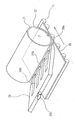
まず、図12及び図13を参照してTFT液晶パネルについて説明する。図12に示すように、TFTアレイ基板20の上には、シール材101がその縁に沿って設けられており、その内側に並行して、例えばブラックマトリクス109と同じ或いは異なる材料からなる遮光性の周辺見切り102が設けられている。シール材101の外側の領域には、データ線駆動回路103及び実装端子104がTFTアレイ基板20の一辺に沿って設けられており、走査線駆動回路105が、この一辺に隣接する二辺に沿って設けられている。更に、TFTアレイ基板20の残る一辺には、画面表示領域の両側に設けられた走査線駆動回路105間をつなぐための複数の配線106が設けられている。また、シール材101の四隅には、TFTアレイ基板20と対向基板108との間で電気的導通をとるための導通材からなる銀点107が設けられている。そして、図13に示すように、図12に示したシール材101とほぼ同じ輪郭を持つ対向基板108が該シール材101を介してTFTアレイ基板20に固着されている。
First, a TFT liquid crystal panel will be described with reference to FIGS. As shown in FIG. 12, a sealing
データ線駆動回路103及び走査線駆動回路105は、配線を介してソース電極としてのデータ線及びゲート電極としての走査線(共に図示せず。)にそれぞれ電気的に接続されている。データ線駆動回路103には、制御回路(図示せず。)から即時表示可能な形式に変換された画像信号が入力され、走査線駆動回路105がパルス的に走査線に順番にゲート電圧を送るのに合わせて、データ線駆動回路103は画像信号に応じた信号電圧をデータ線(ソース電極)に送る。この実施の形態では特に、TFT111はp−Si(ポリシリコン)タイプのTFTであるので、TFT111の形成時に同一工程で、データ線駆動回路103及び走査線駆動回路105を形成することも可能であり、製造上有利である。
The data line driving
図14を参照して、上記TFT液晶パネルの組立工程の一例を簡単に説明すると、TFTアレイ基板(素子基板)20及び対向基板108を受入れ洗浄した後、両基板20,106の表面にポリイミド、ポリビニルアルコール等の配向膜をそれぞれ形成し、次いで、この配向膜の表面にレーヨン或いはナイロン等のクロス材22を用いてラビングを施した後、洗浄する。次いで、TFTアレイ基板20側に上述したシール材101をスクリーン印刷等で形成するとともに、導通材である銀点107を塗布する。
Referring to FIG. 14, an example of the assembly process of the TFT liquid crystal panel will be briefly described. After receiving and cleaning the TFT array substrate (element substrate) 20 and the
次に、両基板20,108をシール材101を介して貼り合わせ、セルギャップ等のアライメントを行った後、ある程度の圧力を加えて両基板20,108を圧着させる。次いで、シール材101が光硬化性を備えている場合には、光を照射して硬化させ、かかる硬化後に両基板20,108間に液晶112を注入し、注入完了後、注入口を封止材110によって封止する。次いで、洗浄を施した後、所定の検査をし、合格したものが実装に供される。
Next, the two
ここで、この実施の形態では、上述した両基板20,108に対するラビング処理を次のようにして行っている。なお、以下に示す第1〜第9の実施形態ではTFTアレイ基板20(以下、単に基板20という。)のみを例に採って説明するが、これに限られるものではない。また、各実施形態については、基板20の表面を擦るためのラビング処理部材として、従来例と同様に基板20に対して回転するラビングローラ21を例にとり、更に、従来例(図15)と重複する部分には同一符号を付してその説明を省略する。
Here, in this embodiment, the rubbing process for both the
図1は本発明に係るラビング方法及びラビング装置の第1実施形態を説明するための概略説明図である。 FIG. 1 is a schematic explanatory view for explaining a first embodiment of a rubbing method and a rubbing apparatus according to the present invention.
基板20とラビングローラ21との接触部分から配向膜の一部若しくはクロス材(ラビング布)22の毛(パーティクル)等が粉塵として発生する。この粉塵は、上述のような基板20の搬送方向及びラビングローラ21の回転方向を採用した場合、基板20とラビングローラ21との接触部分に対して図示左側に多く発生する。
Part of the alignment film or bristles (particles) of the cloth material (rubbing cloth) 22 is generated as dust from the contact portion between the
この実施形態では、上記接触部分の左側上方に吸引口23aを配置した吸引部材23を設け、吸引口23aから上記接触部分で発生した粉塵を吸引して系外に排出するものである。吸引部材23としては、図示しない吸引ファン等によって強制的に空気を吸引するものでよいが、排気口をクリーンルーム内に設ける場合には高密度フィルタ等を備える必要があるため、排気口は室外に設けることが好ましい。ここで、吸引口23aはラビングローラ21の軸線方向に延長された形状を備えており、基板20とラビングローラ21との接触部分に対し、ほぼ平行に配置された開口位置を備えている。
In this embodiment, a
この実施形態では、吸引口23aから空気を吸入することによって、ラビングローラ21によって巻き上げられた粉塵が吸引され、排出されるので、周囲環境に粉塵が撒き散らされるのを防止することができるとともに、粉塵がクロス材22や基板20の表面上に堆積して悪影響を及ぼすことを防止できる。また、一旦基板20及びクロス材22の表面に付着した粉塵も、吸引口23aが基板20の表面及びクロス材22の表面に対向して設けられているため、吸引力によってある程度引き離され、吸引される。
In this embodiment, dust sucked up by the rubbing
図2は本発明に係る第2実施形態を説明するための概略説明図である。 FIG. 2 is a schematic explanatory diagram for explaining a second embodiment according to the present invention.
この実施形態においては、上記第1実施形態と同様に吸引部材24の先端部に吸引口24aが形成され、吸引口24aから粉塵を吸引するようになっているが、吸引部材24の先端寄りに、少なくとも図2に示す縦断面上において絞られた形状として形成された先端部24bが設けられ、その最先端に吸引口24aが形成されている点で異なる。
In this embodiment, as in the first embodiment, a
この実施形態では、吸引部材24の先端部24bが絞られた形状となっているため、基板20とラビングローラ21との接触部分(すなわち粉塵の発生部)により近い部分に吸引口24aを配置することができるとともに、絞り込んだ先に吸引口24aを形成しているので、吸引力を高めることができ、より確実に粉塵を吸引でき、かつ、より強力に粉塵を基板20及びクロス材22の表面から離反させることができる。
In this embodiment, since the
ここで、吸引部材24は上記第1実施形態と同様の吸引ファン等に接続されていてもよいが、特に、真空ポンプ等に接続された排気系に接続することによって強力な吸引力を発揮することができる。
Here, the
この実施形態では、吸引口24aは、ラビングローラ21の表面よりも基板20の表面に向けて開口しており、基板20の表面上に堆積した粉塵をより確実に吸引できるようになっている。
In this embodiment, the
図3は本発明に係る第3実施形態の構造を示す概略斜視図である。 FIG. 3 is a schematic perspective view showing the structure of the third embodiment according to the present invention.
この実施形態においては、上記第2実施形態とほぼ同様の吸引部材25を備えている。吸引部材の先端寄りには絞られた形状の先端部25bが形成され、この先端部25bの最先端に開口した吸引口25aが形成されている。なお、吸引部材25の上端に設けられた接続管25cは、図示しない排気系に接続されるようになっている。
In this embodiment, a
この実施形態では、先端部25bの先端に形成された吸引口25aはややラビングローラ21の周面側に向けて開口しており、基板20とクロス材22との接触部分において発生した粉塵を吸引するとともに、主としてクロス材22の表面に付着した粉塵を吸引するように構成されている。
In this embodiment, the
図4に示すものは本発明に係る第4実施形態である。 FIG. 4 shows a fourth embodiment according to the present invention.
この実施形態においては、吸引部材26がラビングローラ21の軸線方向に並列した複数の分割吸引部26dに分割されている。各分割吸引部26dの先端寄りには、第2及び第3実施形態と同様に絞られた形状の先端部26bが形成され、その最先端に開口部を持つ吸引口26aがそれぞれ形成されている。接続管26cは図示しない排気系に接続されるためのものである。
In this embodiment, the
この実施形態では、吸引口26aを分割することによって、全体としても吸引口26aの開口面積を低減し、各吸引口26aにおける吸引力を高めるようにしている。この結果、単に大気中に巻き上げられた粉塵のみではなく、基板20の表面やクロス材22の表面に付着した粉塵をも離反させ、吸引除去する能力を高めることができる。
In this embodiment, by dividing the
図5は本発明に係る第5実施形態の全体構造を示す概略斜視図である。 FIG. 5 is a schematic perspective view showing the overall structure of the fifth embodiment according to the present invention.
この実施形態においては、ラビングローラ21の周面をほぼ全面的に包囲するように、一部切り欠き部を備えた円筒形状に形成された吸引部材27が設けられている。この吸引部材27には、基板20とラビングローラ21との接触部分に対して基板20の移動方向の前側及び後側に位置する吸引口27a,27bと、ラビングローラ21の周面に貼着されたクロス材22に対向する吸引口27cとが設けられている。
In this embodiment, a
ここで、ラビングローラ21の周面に対向する吸引口27cは、ラビングローラ21の周面に対向する面全体が開口した構造となっていてもよく、或いは細かい吸引口を多数分散配置させた構造となっていてもよい。なお、接続管27dは図示しない排気系への接続部を構成するものである。この実施形態によれば、基板20とラビングローラ21の接触部分の前後に加えて、ラビングローラ21の周面のほぼ全体から吸引を行うようになっているため、粉塵を確実に捕捉することができ、特にクロス材22から粉塵を効果的に除去することができる。また、この実施形態では、吸引部材27がラビングローラ21を包囲するように配置されているため、吸引部材がラビングローラ21から離れて突出することもないから、装置全体を小型化することができる。
Here, the
図6は本発明に係る第6実施形態の全体構成を示す概略斜視図、図7はこの実施形態の吸引口近傍を示す拡大断面図である。 FIG. 6 is a schematic perspective view showing the overall configuration of the sixth embodiment according to the present invention, and FIG. 7 is an enlarged sectional view showing the vicinity of the suction port of this embodiment.
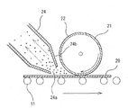
この実施形態では、基板20とラビングローラ21との接触部分の一側に、吸引部材28の吸引口28aを配置し、その吸引口28aの近傍に、ラビングローラ21の周面に対してエアを吹き付けるための吹付部材29の吹付口29aを配置している。
In this embodiment, the
吸引口28aは、上記各実施形態と同様に先端側がやや絞られた吸引部材28の先端に形成され、上記接触部分から発生する粉塵を吸引するとともに、ラビングローラ21の周面のクロス材22に付着した粉塵をも吸引できるように構成されている。
The
吹付部材29の内部には、簡略化して示すイオン化電極29b,29cが設置されており、このイオン化電極29bと29cとの間に高周波電圧を印加することによって、図示しないエアコンプレッサ等からなる給気装置から送られるエアをイオン化するようになっている。イオン化されたエアは吹付口29aからクロス材22の表面へと吹き付けられ、付着している粉塵をクロス材22から離反させる。クロス材22から離反された粉塵は、上記吸引口28aから吸引され、排出される。
上記吸引部材28及び吹付部材29の両側(ラビングローラ21の回転方向の前後両側)には、気流制御板31,32がそれぞれ配置されている。これらの気流制御板31,32は、吹付部材29から吹き付けられたエアを周囲に広げることなく、効率的に吸引口28aから排出されるようにするためのものである。これらの気流制御板31,32によって、吸引部材28に吸込まれない粉塵が周囲に撒き散らされることを防止できる。
上記吹付部材29にはイオン化電極を設け、エアをイオン化して吹き付けるようにすることによって、粉塵の離反を促進させている。しかし、エアのイオン化手段を設けなくても、吹付力によってある程度の粉塵を離反させることは可能である。
The
吹付手段において吹き付けるものとしては、エアに限らず、不活性ガスや純水等の、被処理物に影響を与えないものでありさえすれば、種々の他の流体を用いることができる。 What is sprayed by the spraying means is not limited to air, and various other fluids such as inert gas and pure water can be used as long as they do not affect the object to be processed.
上記吹付手段及び吸引手段は、粉塵の発生部である、基板20とラビングローラ21との接触部分に対して設けることが最も効果的であるが、ラビングローラ21の表面に対しても、さらにはラビング処理後の基板表面に対しても作用するように、一体に、或いは、それぞれ適用部位毎に別体のものとして設けることが好ましい。
It is most effective to provide the spraying means and the suction means on the contact portion between the
なお、上記各実施形態においては、ラビングローラ21に貼着されたクロス材22によって基板20の表面を擦るラビング処理に対して説明を行ってきたが、、その他の種々のラビング処理部材によって擦る方法により行うラビング方法及び装置に広く適用できるのは勿論である。
In each of the embodiments described above, the rubbing process in which the surface of the
図8は本発明に係る第7実施形態を説明するための概略説明図、図9は図8を部分的に拡大した概略断面図である。 FIG. 8 is a schematic explanatory view for explaining a seventh embodiment according to the present invention, and FIG. 9 is a schematic sectional view partially enlarged from FIG.
この実施形態では、基板20とラビングローラ21との接触部分の図示右側上方に吸引口50aを配置した吸引ノズル50を設け、吸引口50aからラビングローラ21のクロス材22に付着した粉塵を吸引して系外に排出するものである。吸引ノズル50としては、例えば、図示しない真空ポンプ等によって強制的に空気を真空吸引するものでよいが、排気口をクリーンルーム内に設ける場合には高密度フィルタ等を備える必要があるため、排気口は室外に設けることが好ましい。
In this embodiment, a
吸引口50aはラビングローラ21の軸線方向に沿って延在され、且つ、基板20とラビングローラ21との接触部分に対してほぼ平行に配置されたスリット状の開口を備える。また、吸引口50aの周縁部には、石英又はガラス等の非導電材層51がコーティングされている。
The
吸引ノズル50はラビングローラ21の外周部に向けて接近離間移動可能に配置されており、図示しない駆動手段によってラビングローラ21の外周部に対しての接近離間移動がなされる。具体的には、基板20の表面をラビングローラ21によって擦っているときには、駆動手段が吸引ノズル50をラビングローラ21の外周部に接近移動させ、擦っていないときには吸引ノズル50をラビングローラ21の外周部から離間移動させる。
The
ここで、吸引ノズル50がラビングローラ21に接近移動する際には、該吸引ノズル50の吸引口50aの周縁部(非導電材層51)がラビングローラ21のクロス材22の毛足部22aに接触する位置で吸引ノズル50の移動が停止される。この場合、図9に示すように、毛足部22aに接触する吸引口50a周縁部の位置が、クロス材22の毛足部22aの長さをLとした場合に該毛足部22aの先端部からL/2までの範囲内で吸引ノズル50の移動が停止されるようにするのが好ましい。
Here, when the
この実施形態では、ラビング時においては吸引ノズル50の吸引口50aの周縁部がラビングローラ21の外周部のクロス材22の毛足部22aに接触して配置されているため、クロス材22に付着した粉塵が、該クロス材22が基板20に接触する前に強力な吸引力で吸引除去される。この結果、クロス材22が基板20に接触する前において該クロス材22は常にクリーンな状態とされ、この状態で基板20を擦ることが可能になって、基板20への粉塵の付着が良好に防止される。
In this embodiment, during rubbing, the peripheral portion of the
また、毛足部22aの先端部から該毛足部22aの長さLの1/2までの範囲内に吸引ノズル50の吸引口50aの周縁部を位置させることにより、吸引口50aの周縁部のクロス材22の地肌への不用意な接触が回避されるため、吸引口50aの周縁部の毛足部22aへの接触を確保して強力な吸引力を維持する一方において、クロス材22の地肌が吸引口50aの周縁部によって削り取られて基板20上に落下するのを確実に防止することができる。
Further, by positioning the peripheral edge of the
更に、基板20の表面がラビングローラ21によって擦られていないときは、吸引ノズル50がラビングローラ21の外周部から離間配置されて該吸引ノズル50の吸引口50aの周縁部と毛足部22aとの接触がなくなるため、該周縁部と毛足部22aとの接触(摩擦)による熱影響及び該接触によるラビングローラ21の劣化を軽減することができ、この結果、ラビングローラ21の寿命向上を図ることができる。
Further, when the surface of the
更に、吸引口50aの周縁部には非導電材層51が配置されているため、吸引口50aの周縁部と毛足部22aとが長期間に渡って接触して万が一に該周縁部が削れた場合に、落下した削り屑が基板20の表面に付着した状態で液晶が封入されて製品化されたとしても、該削り屑が非導電材であるため製品使用時のショートを確実に防止することができる。この場合、非導電材層51を石英又はガラスで構成することにより、吸引口50aの周縁部の耐久性の向上を図るとができるとともに、該周縁部に容易に鏡面部を形成することができる。
Furthermore, since the
なお、この実施の形態では、吸引ノズル50を基板20とラビングローラ21との接触部分の図示右側上方に配置して吸引口50aをクロス材22の毛足部22aに接触させているが、これに限定されず、吸引ノズル50を基板20とラビングローラ21との接触部分の図示左側上方或いは図示中央部上方に配置して吸引口50aをクロス材22の毛足部22aに接触させるようにしてもよい。
In this embodiment, the
図10は本発明に係る第8実施形態を説明するための概略説明図である。 FIG. 10 is a schematic explanatory diagram for explaining an eighth embodiment according to the present invention.
この実施形態は、第7実施形態の吸引ノズル50の吸引口50aに櫛部60を配置した点の除いてその構成が第7実施形態と同一であるため、第7実施形態と重複する部分については同一符号を付してその説明を省略し、相違点を説明する。
This embodiment has the same configuration as that of the seventh embodiment except that the
吸引ノズル50の吸引口50aにはクロス材22の毛足部22aに接触する櫛部60が取り付けられており、該櫛部60は吸引口50aと同様にラビングローラ21の軸線方向に沿って延在されるとともに、基板20とラビングローラ21との接触部分に対してほぼ平行に配置され、且つ、先端部が吸引口50aの周縁部と略面一とされている。
A
この実施の形態では、ラビング時において、吸引口50aに設けられた櫛部60によって毛足部22aの毛並みが揃えられるとともに、該櫛部60が毛足部22aに付着した粉塵をたたき出すため吸引口50aからの粉塵の吸引効果を高めることができる。なお、その他の作用効果は上述した第7実施形態と同様であるのでその説明を省略する。
In this embodiment, at the time of rubbing, the
図11は本発明に係る第9実施形態を説明するための概略説明図である。 FIG. 11 is a schematic explanatory diagram for explaining a ninth embodiment according to the present invention.
この実施形態は、第1実施形態(図1参照)の吸引部材23を基板20とラビングローラ21との接触部分の図示左側(粉塵が多く発生する側)上方に配置するとともに、第7実施形態(図8及び図9参照)の吸引ノズル50を該接触部分の図示右側上方に配置したものである。なお、吸引部材23及び吸引ノズル50はそれぞれ第1実施形態及び第7実施形態で説明済であるため、重複する部分に同一符号を付してその説明を省略する。
In this embodiment, the
この実施形態では、ラビング時において、ラビングローラ21によって巻き上げられた粉塵が吸引部材23の吸引口23aから吸引されて排出されるので、周囲環境に粉塵が撒き散らされるのを防止することができるとともに、粉塵がクロス材22や基板20の表面上に堆積して悪影響を及ぼすことを防止でき、更に、一旦基板20及びクロス材22の表面に付着した粉塵も、吸引口23aが基板20の表面及びクロス材22の表面に対向して設けられていることにより、吸引力によってある程度引き離されて吸引され、しかも、吸引ノズル50によってクロス材22に付着した粉塵が、該クロス材22が基板20に接触する前に強力な吸引力で吸引除去されるので、ラビングローラ21の外周部を常にクリーンな状態にして基板20を擦ることが可能になって基板20への粉塵の付着を防止することができる。この結果、TFTの品質を更に高めることができるとともに、製造工程におけるクリーン度の管理についても、従来必要であったラビング工程及洗浄工程とその他の製造工程との環境仕切りを不要にすることが可能になった。なお、その他の作用効果については、第7実施形態と同様であるのでその説明を省略する。
In this embodiment, during rubbing, the dust wound up by the rubbing
11 搬送ローラ
20 基板
21 ラビングローラ
22 クロス材
22a 毛足部
23,24,25,26,27,28 吸引部材
23a,24a,25a,26a,27a,28a 吸引口
29 吹付部材
29a 吹付口
29b,29c イオン化電極
50 吸引ノズル
50a 吸引口
51 非導電材
60 櫛部
L 毛足部の長さ
11 Conveying
Claims (7)
前記基板と前記ラビング処理部材との接触部に向かって開口した吸引口を有する吸引部材を備える吸引手段と、前記接触部に向かって開口した吹付口を有する吹付手段とを用いて、前記基板と前記ラビング処理部材との少なくとも一方から発生する粉塵を吸引しながらラビング処理を行う工程を有し、
前記ラビング処理を行う工程において、吹付口から、前記ラビング処理部材又は前記基板に対して流体を吹き付けることを特徴とする基板のラビング方法。 In a method for rubbing a substrate in which a substrate used for a liquid crystal electro-optical element is rubbed with a rubbing treatment member,
Using the suction means including a suction member having a suction port opened toward the contact portion between the substrate and the rubbing processing member, and the spraying means having a spray port opened toward the contact portion, Having a step of rubbing while sucking dust generated from at least one of the rubbing members,
In the step of performing the rubbing treatment, a substrate rubbing method, wherein a fluid is sprayed from the spray port to the rubbing treatment member or the substrate.
前記基板と前記ラビング処理部材とを相対的に動作させて前記基板を前記ラビング処理部材によって擦るように駆動する駆動手段と、
前記基板と前記ラビングローラとの接触部に向かって開口した吸引口を有し、前記基板と前記ラビング処理部材との少なくとも一方から発生する粉塵を吸引する吸引手段と、
前記ラビング処理部材又は前記基板に対して流体を吹き付ける吹付手段と、を備え、
前記吹付手段は、前記接触部に向かって開口した吹付口を有することを特徴とする基板のラビング装置。 A rubbing treatment member for rubbing a substrate used in a liquid crystal electro-optic element;
Driving means for relatively moving the substrate and the rubbing processing member to drive the substrate to be rubbed by the rubbing processing member;
A suction means having a suction port opened toward a contact portion between the substrate and the rubbing roller, and sucking dust generated from at least one of the substrate and the rubbing processing member;
Spraying means for spraying fluid against the rubbing treatment member or the substrate,
The substrate rubbing apparatus, wherein the spraying means has a spraying opening opened toward the contact portion.
Priority Applications (1)
| Application Number | Priority Date | Filing Date | Title |
|---|---|---|---|
| JP2003350798A JP3966267B2 (en) | 1997-01-08 | 2003-10-09 | Substrate rubbing method and rubbing apparatus |
Applications Claiming Priority (2)
| Application Number | Priority Date | Filing Date | Title |
|---|---|---|---|
| JP157797 | 1997-01-08 | ||
| JP2003350798A JP3966267B2 (en) | 1997-01-08 | 2003-10-09 | Substrate rubbing method and rubbing apparatus |
Related Parent Applications (1)
| Application Number | Title | Priority Date | Filing Date |
|---|---|---|---|
| JP189498A Division JP3792384B2 (en) | 1997-01-08 | 1998-01-07 | Substrate rubbing method, liquid crystal electro-optic element manufacturing method, and substrate rubbing apparatus |
Publications (3)
| Publication Number | Publication Date |
|---|---|
| JP2004046248A JP2004046248A (en) | 2004-02-12 |
| JP2004046248A5 JP2004046248A5 (en) | 2005-07-07 |
| JP3966267B2 true JP3966267B2 (en) | 2007-08-29 |
Family
ID=31716993
Family Applications (1)
| Application Number | Title | Priority Date | Filing Date |
|---|---|---|---|
| JP2003350798A Expired - Fee Related JP3966267B2 (en) | 1997-01-08 | 2003-10-09 | Substrate rubbing method and rubbing apparatus |
Country Status (1)
| Country | Link |
|---|---|
| JP (1) | JP3966267B2 (en) |
Families Citing this family (2)
| Publication number | Priority date | Publication date | Assignee | Title |
|---|---|---|---|---|
| JP5322909B2 (en) * | 2009-12-08 | 2013-10-23 | 富士フイルム株式会社 | Rubbing treatment method, optical compensation film manufacturing method |
| KR101382723B1 (en) * | 2012-06-15 | 2014-04-08 | 하이디스 테크놀로지 주식회사 | Rubbing device of an alignment layer for liquid crystaldisplay device |
-
2003
- 2003-10-09 JP JP2003350798A patent/JP3966267B2/en not_active Expired - Fee Related
Also Published As
| Publication number | Publication date |
|---|---|
| JP2004046248A (en) | 2004-02-12 |
Similar Documents
| Publication | Publication Date | Title |
|---|---|---|
| US7806986B2 (en) | Substrate cleaning apparatus and substrate cleaning method using the same | |
| KR20070002455A (en) | Coater and operating method thereof | |
| JP4007303B2 (en) | Substrate rubbing method and rubbing apparatus | |
| JP4289102B2 (en) | Assembling apparatus, assembling method, and terminal cleaning apparatus | |
| JP3792384B2 (en) | Substrate rubbing method, liquid crystal electro-optic element manufacturing method, and substrate rubbing apparatus | |
| JP2006272223A (en) | Foreign matter eliminating device, substrate holding device, manufacturing method of electro-optical device and method for removing foreign matter | |
| JP3966267B2 (en) | Substrate rubbing method and rubbing apparatus | |
| KR20170048136A (en) | Cleaning head and cleaning method | |
| JP3966266B2 (en) | Substrate rubbing method and rubbing apparatus | |
| JP2005238109A (en) | Apparatus and method for cleaning substrate, and method for manufacturing electro-optics device | |
| JP2002023143A (en) | Device for removing foreign matter for liquid crystal device and method therefor | |
| WO2006064596A1 (en) | Substrate cleaning device and cleaning method | |
| JPH09234432A (en) | Method for cleaning liquid crystal display panel and cleaner therefor | |
| JP2004105848A (en) | Equipment and method for cleaning substrate | |
| KR20120131994A (en) | Dry cleaner | |
| JP2002307023A (en) | Brush washing apparatus provided with self washing function and method of manufacturing flat display apparatus or semiconductor element using the same | |
| KR20150027600A (en) | Cleaning apparatus and method of fabricating the display device including cleaning using the same | |
| JP3050957B2 (en) | Liquid crystal display element manufacturing method | |
| KR20070060713A (en) | Apparatus and method for cleaning a substrate | |
| JP6240777B2 (en) | Cleaning device | |
| US20090060577A1 (en) | Plate, and pattern forming device and pattern forming method using the same plate | |
| KR20050066267A (en) | Apparatus for cleaning in liquid crystal display device | |
| JP2019139079A (en) | Method for manufacturing liquid crystal panel substrate | |
| JPH06250162A (en) | Production of liquid crystal display element | |
| KR100824417B1 (en) | Apparatus And Method Of Uniting Of Flat Display Panel Integrated Film Type Touch Panel |
Legal Events
| Date | Code | Title | Description |
|---|---|---|---|
| A521 | Written amendment |
Free format text: JAPANESE INTERMEDIATE CODE: A523 Effective date: 20050107 |
|
| A621 | Written request for application examination |
Free format text: JAPANESE INTERMEDIATE CODE: A621 Effective date: 20050107 |
|
| A977 | Report on retrieval |
Free format text: JAPANESE INTERMEDIATE CODE: A971007 Effective date: 20070117 |
|
| A131 | Notification of reasons for refusal |
Free format text: JAPANESE INTERMEDIATE CODE: A131 Effective date: 20070206 |
|
| A521 | Written amendment |
Free format text: JAPANESE INTERMEDIATE CODE: A523 Effective date: 20070327 |
|
| RD04 | Notification of resignation of power of attorney |
Free format text: JAPANESE INTERMEDIATE CODE: A7424 Effective date: 20070403 |
|
| TRDD | Decision of grant or rejection written | ||
| A01 | Written decision to grant a patent or to grant a registration (utility model) |
Free format text: JAPANESE INTERMEDIATE CODE: A01 Effective date: 20070508 |
|
| A61 | First payment of annual fees (during grant procedure) |
Free format text: JAPANESE INTERMEDIATE CODE: A61 Effective date: 20070521 |
|
| R150 | Certificate of patent or registration of utility model |
Free format text: JAPANESE INTERMEDIATE CODE: R150 |
|
| FPAY | Renewal fee payment (event date is renewal date of database) |
Free format text: PAYMENT UNTIL: 20110608 Year of fee payment: 4 |
|
| FPAY | Renewal fee payment (event date is renewal date of database) |
Free format text: PAYMENT UNTIL: 20110608 Year of fee payment: 4 |
|
| FPAY | Renewal fee payment (event date is renewal date of database) |
Free format text: PAYMENT UNTIL: 20120608 Year of fee payment: 5 |
|
| FPAY | Renewal fee payment (event date is renewal date of database) |
Free format text: PAYMENT UNTIL: 20130608 Year of fee payment: 6 |
|
| FPAY | Renewal fee payment (event date is renewal date of database) |
Free format text: PAYMENT UNTIL: 20130608 Year of fee payment: 6 |
|
| LAPS | Cancellation because of no payment of annual fees |