JP3961779B2 - Vehicle seat reclining device - Google Patents
Vehicle seat reclining device Download PDFInfo
- Publication number
- JP3961779B2 JP3961779B2 JP2001101177A JP2001101177A JP3961779B2 JP 3961779 B2 JP3961779 B2 JP 3961779B2 JP 2001101177 A JP2001101177 A JP 2001101177A JP 2001101177 A JP2001101177 A JP 2001101177A JP 3961779 B2 JP3961779 B2 JP 3961779B2
- Authority
- JP
- Japan
- Prior art keywords
- cam
- lock
- plate
- lock tooth
- machine frame
- Prior art date
- Legal status (The legal status is an assumption and is not a legal conclusion. Google has not performed a legal analysis and makes no representation as to the accuracy of the status listed.)
- Expired - Lifetime
Links
Images


Description
【0001】
【発明の属する技術分野】
この発明は、座面となるシートクッションに対して背もたれとなるシートバックを回転可能に取り付けるための車両用シートリクライニング装置に関する。
【0002】
【従来の技術】
従来、この種の車両用シートリクライニング装置としては、例えば特開平7−136032号公報に示されているものが知られている。即ち、シートクッション側のベースプレートに取り付けられた機枠と、シートバック側のアームプレートに取り付けられた蓋体とが相互に回動可能に構成され、機枠内に配置したロックツースの歯と蓋体の内周面に形成した内歯ギヤとの噛合によって機枠と蓋体との相互回転を阻止するようになっている。即ち、機枠と蓋体とを貫通して設けられた操作軸を介してカム状板を所定量回転することにより、ロックツースを内歯ギヤ側に移動させ、このロックツースの歯と内歯ギヤと噛合とを噛合させるようになっている。また、上記操作軸を介してカム状板を反対方向に回転させることにより、カム状板によって直接あるいは間接部材を介してロックツースを内歯ギヤから離れる方向に移動させ、ロックツースの歯と内歯ギヤとのロック状態を解除するようになっている。
【0003】
また、カム状板は、周方向に180度離れた位置にある2つのロックツースを内歯ギヤ側に同時に移動させるようになっている。このため、カム状板は、その中心部に、ロックツースとカム状板とが押圧する方向に長く形成された長孔を有し、この長孔に挿通された操作軸との隙間の分だけカム状板を長孔に沿って移動可能にすることにより、カム状板と2つのロックツースとの押圧力のバランスがくずれるのを防止して、ロックツースの歯と内歯ギヤとが半噛み状態になるのを阻止できるようになっている。
【0004】
【発明が解決しようとする課題】
上述したように、操作軸を回転させることによりカム状板を介してロックツースをロック方向及びロック解除方向に移動させるように構成された車両用シートリクライニング装置では、ロックツースの歯と内歯ギヤとが半噛み状態になるのを阻止するために、カム状板と操作軸との間に少量のクリアランスを付与しているが、このクリアランスによりカム状板と操作レバーが取り付けられた操作軸との間にガタが発生し、操作レバーのガタ及び異音が発生するという問題があった。
【0005】
そこで、従来は操作レバーにスプリングを設けることによりカム状板と操作軸との間のガタを防止し、異音の発生を防止している。このため、部品点数が増加すると共に、組付け工数も増加する等の問題があった。
【0006】
この発明は、上記問題点を解決するためなされたもので、カム状板とロックツースとの押圧力のバランスを維持しつつ、異音の発生を防止することができる車両用シートリクライニング装置を提供することを課題としている。
【0007】
【課題を解決するための手段】
上記課題を解決するために、請求項1記載の発明は、機枠(10)と、この機枠(10)に回転可能に取り付けられ、内周面に沿って内歯ギヤ(61)を有する蓋体(60)と、前記機枠(10)に取り付けられ、前記内歯ギヤ(61)に噛合可能な歯(21)を有するロックツース(20)と、所定の角度回転した際に、前記ロックツース(20)の被ロックカム面(25)を押圧して該ロックツース(20)を内歯ギヤ(61)側に移動させ前記歯(21)を内歯ギヤ(61)に噛合させるロックカム面(41)を有する回転式のカム状板(40)とを備え、前記機枠(10)及び蓋体(60)の一方をシートクッション(150)側に連結し、他方をシートバック(160)側に連結した状態で、前記ロックツース(20)の歯(21)を内歯ギヤ(61)における異なる位置に噛合させることによりシートバック(160)の傾きを変更するようになっており、前記ロックツース(20)は、機枠(10)における周方向に180度離れた位置に配置され、前記ロックカム面(41)は、カム状板(40)における回転軸回りに180度離れた位置に形成され、前記カム状板(40)には、各ロックカム面(41)を結ぶ線(L1)に対して略直交する線(L2)上の位置であって回転軸回りに180度離れた位置に回転軸を中心とする円弧状の被拘束外周面(45)を設け、前記機枠(10)には、各ロックツース(20)の被ロックカム面(25)を結ぶ線(L3)に対して略直交する線(L4)上の位置であって周方向に180度離れた位置にガイド部(11A)を設け、このガイド部(11A)には、前記各被拘束外周面(45)に摺接するとともに前記各ロックツース(20)の前記被ロックカム面(25)を結ぶ線(L3)に対して略平行な平面状に形成された摺接面(11c)を設けていることを特徴としている。
【0008】
請求項2記載の発明は、請求項1記載の発明において、前記カム状板(40)の外周面には、前記ロックカム面(25)を前記ロックツース(20)の被ロックカム面(25)に係合する方向へ付勢するロックスプリング(70)を係止する係止部(43)が各非拘束外周面(45)に隣接した180度の間隔で形成されていることを特徴としている。
【0009】
そして、上記のように構成された請求項1記載の発明においては、ロックツース(20)が機枠(10)における周方向に180度離れた位置に配置され、ロックカム面(41)がカム状板(40)における回転軸回りに180度離れた位置に形成され、カム状板(40)には各ロックカム面(41)を結ぶ線(L1)に対して略直交する線(L2)上の位置であって回転軸回りに180度離れた位置に被拘束外周面(45)を設け、機枠(10)には各ロックツース(20)の被ロックカム面(25)を結ぶ線(L3)に対して略直交する線(L4)上の位置であって周方向に180度離れた位置にガイド部(11A)を設け、このガイド部(11A)には各被拘束外周面(45)に摺接する摺接面(11c)を設けているので、カム状板(40)の回転の自由性及びロックツース(20)が設置されている方向へのカム状板(40)の移動の自由性を確保することができると共に、ロックツース(20)が設けられている方向とは略直交する方向へのカム状板(40)の移動を防止して、カム状板(40)の位置の安定化を図ることができる。
【0010】
即ち、カム状板(40)は各ロックツース(20)との押圧力のバランスがとれた位置に移動することができるので、各ロックツース(20)の歯(21)を内歯ギヤ(61)に確実に噛合させることができる。しかも、この押圧力のバランスをとるために、カム状板(40)の例えば回転中心孔にガタを有する操作軸を嵌合する必要がないので、そのガタによる異音の発生を防止することができると共に、その異音を防止するためのスプリングなどの部品の点数やその部品を組み込むための工数を低減することができる。
【0011】
更に、ガイド部(11A)によってカム状板(40)の位置が安定するので、機枠(10)、蓋体(60)、ロックツース(20)、カム状板(40)等の全体を組み立てた後に、例えばカム状板(40)の回転中心孔に操作軸を圧入により固定することも可能になるという利点がある。
【0012】
また、各被拘束外周面(45)がカム状板(40)の回転軸を中心とする円弧状に形成され、該カム状板(40)の回転範囲において常にガイド部(11A)の摺接面(11c)に摺接するようになっているので、カム状板(40)の回転の自由性及びロックツース(20)が設けられている方向へのカム状板(40)の移動の自由性をより確実に確保することができる。
請求項2記載の発明においては、カム状板(40)が、各非拘束外周面(45)に隣接した180度の間隔、つまり軸対称の2ヶ所の位置に設けられた係止部(43)を介して、ロックスプリング(70)からの付勢力を接線方向に効率よく受けることができる。
【0013】
【発明の実施の形態】
以下、この発明の実施の形態を実施例に基づき、図1〜図9を参照して説明する。
【0014】
この実施例で示す車両用シートリクライニング装置Eは、機枠10に形成した円形凹部14の内面側に嵌合すると共に、円形凹部14の内周面に沿って同軸状に回転可能な蓋体60を有し、これらの機枠10及び蓋体60の軸方向の間に配置された揺動式のロックツース20及び回転式のカム状板40を有している。
【0015】
蓋体60には、内周面に沿う互いに対向する2ヶ所の位置に内歯ギヤ61が形成されている。ロックツース20は、機枠10における2ヶ所の位置に揺動自在に取り付けられている共に、上記各内歯ギヤ61に対向する位置にその内歯ギヤ61に噛合可能な外歯ギヤ(歯)21を有している。カム状板40は、このカム状板40の回転中心孔42を中心にして一方向(反時計方向)に回転することにより、2つの各ロックツース20を半径方向外側に押して外歯ギヤ21を内歯ギヤ61に噛合させたり、他方向(時計方向)に回転することによりその噛合を解除させたりするようになっている。
【0016】
また、機枠10及び蓋体60は、その一方がシートクッション150側に連結され、他方がシートバック160側に連結された状態で、前記ロックツース20の外歯ギヤ21が内歯ギヤ61に噛合することにより、シートバック160をシートクッション150に対して所定の角度に保持するようになっている。なお、この実施例では、機枠10をシートクッション150側における幅方向の左右両側の各位置にそれぞれ配置して固定すると共に、蓋体60をシートバック160側における幅方向の左右両側の各位置にそれぞれ固定し、左右両側の操作軸30を後述するセレーション(継手部)32を介して円筒状のシャフト50で連結するようになっている。
【0017】
カム状板40の回転中心孔42には、操作軸30が圧入により固定されるようになっており、この操作軸30は、外部との回転力の伝達を行うためのセレーション32、34を有し、このセレーション32、34における回転方向の所定の位置が機枠10の所定の位置に合わされた状態で、カム状板40の回転中心孔42に圧入されるようになっている。なお、セレーション32は、シャフト50の内面に形成したセレーション(継手部)51に噛み合うように形成されたものであり、セレーション34は、操作レバー31の連結孔に形成されたセレーション35に噛み合うように形成されている。また、これらのセレーション32、34は、凹凸の位置や形状が周方向において一致したものとなっている。
【0018】
また、操作軸30は、カム状板40の回転によりロックツース20の外歯ギヤ21を内歯ギヤ61に噛合し終え、かつ操作軸30のセレーション32、34における回転方向の所定の位置と機枠10の所定の位置と合わせた状態で、その圧入軸部30aをカム状板40の回転中心孔42に圧入するようになっている。回転中心孔42にはセレーション42aが形成されているが、このセレーション42aは、操作軸30の圧入軸部30aを圧入する際の力を軽減すると共に、圧入後の圧入軸部30aをより強固に保持する上で役立つようになっている。
【0019】
更に、シートの左右に配置された各操作軸30のセレーション32とシャフト50のセレーション51とは、回転方向に所定の角度の遊びが生じる噛み合いをもって連結されるようになっている。この遊びは、例えばシートクッション150の左側などの一方の側にベルトアンカなどから大きな力が作用し、その際のシートクッション150の強度メンバ等の弾性変形によりその一方の側の操作軸30が回転してその回転がシャフト50を介して他方の側の操作軸30に伝わり、同他方の側の外歯ギヤ21と内歯ギヤ61との噛合が解除されるのを防止することができる最小限の量に設定されている。
【0020】
また、ロックツース20は、機枠10における周方向に180度離れた位置に配置され、ロックカム面41は、カム状板40における回転中心孔(回転軸)42回りに180度離れた位置に形成されている。カム状板40は、各ロックカム面41を結ぶ線L1に対して略直交する線L2上の位置であって回転中心孔42回りに180度離れた位置に被拘束外周面45を有し、機枠10は、各ロックツース20の被ロックカム面25を結ぶ線L3に対して略直交する線L4上の位置であって周方向に180度離れた位置に後述する第1ガイド凸部(ガイド部)11Aを有している。この第1ガイド凸部11Aには、各被拘束外周面45に摺接する摺接面11cが形成されている。そして、各被拘束外周面45は、カム状板40の回転中心孔42を中心とする円弧状の曲面によって形成され、該カム状板40の回転範囲において常にガイド部11Aの摺接面11cに摺接するようになっている。なお、摺接面11cは各ロックツース20の被ロックカム面25を結ぶ線L3に対して略平行な平面状に形成されおり、カム状板(40)が各被ロックカム面25方向に移動するのを許容するようになっている。
【0021】
以下、上記構成についてさらに詳細に説明する。
【0022】
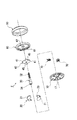
機枠10は、その外側面がシートクッション150の強度メンバの一部を構成するベースプレート110に溶接やボルト等で固定され、蓋体60は、その外側面がシートバック160の強度メンバの一部を構成するアームプレート120に溶接やボルト等で固定されるようになっている。また、機枠10及び蓋体60と同軸状の位置には、アームプレート120をフロント(F)方向に付勢して、シートバック160を前方に倒すためのうず巻スプリング130が装着されている。
【0023】
機枠10は、全体として円板状に形成されたものであって、円形状の内周面14aを外周近傍位置に同軸状に形成することにより、円形凹部14を有するように構成したものである。また、機枠10には、その軸心位置に、操作軸30を挿通するための回転中心孔17が形成されている。
【0024】
また、円形凹部14の底面からは、第1ガイド凸部11A、第2ガイド凸部11B、凸部13、軸部16が2つずつ突設されている。軸部16は、ロックツース20を揺動自在に支持するようになっている。第1ガイド凸部11Aは、軸部16回りに揺動するロックツース20の第1外周面27を摺動自在に案内するガイド面11aを有しており、第2ガイド凸部11Bは、同じく軸部16回りに揺動するロックツース20の第2外周面28を摺動自在に案内するガイド面11bを有している。第1外周面27、第2外周面28、ガイド面11a、11bは、軸部16によるロックツース20の回転中心に対して同軸状の円弧状に形成されている。また、第1ガイド凸部11Aには、回転中心側を向く面に上述した摺接面11cが形成されている。
【0025】
凸部13は、一方の第1ガイド凸部11Aと他方の第2ガイド凸部11Bとの間、及び他方の第1ガイド凸部11Aと一方の第2ガイド凸部11Bとの間に配置されており、ロックスプリング70の基部70aを保持するようになっている。
【0026】
ロックスプリング70は、うず巻スプリング状に形成されており、カム状板40を、図1において反時計方向に回転するように付勢するようになっている。また、ロックスプリング70は、カム状板40を反時計方向に回転させることにより、ロックツース20の外歯ギヤ21を内歯ギヤ61に常時噛合させるように付勢するようになっている。
【0027】
また、上記第1ガイド凸部11A、第2ガイド凸部11B、凸部13、軸部16は、プレスを用いたエンボス加工により機枠10に一体に形成されている。
【0028】
蓋体60も、機枠10と同様に円板状に形成されたものであり、機枠10の内周面14aに回転自在に嵌合するリム部60aの内周面に沿って、上述した内歯ギヤ61が設けられている。この蓋体60には、その軸心位置に、操作軸30を挿通するための回転中心孔62が形成されている。
【0029】
また、蓋体60及び機枠10は、その外周部がリング状のホルダ80によって挟持するように覆われており、これにより軸方向に分離されることなく相互に回転可能に保持されている。
【0030】
ロックツース20は、軸部16の一方の側であって内歯ギヤ61に対向する部分に上述した外歯ギヤ21を有し、また、この外歯ギヤ21の背面側にカム状板40のロックカム面41から力を受ける被ロックカム面25を有している。即ち、ロックツース20は、その被ロックカム面25でロックカム面41から力を受けることにより、軸部16を中心にして時計方向に揺動し、外歯ギヤ21が内歯ギヤ61に噛合するようになっている。
【0031】
外歯ギヤ21は、軸部16に接近した位置まで形成され、この外歯ギヤ21と、内歯ギヤ61の歯は、その圧力角を60〜90°に設定されている。しかも、外歯ギヤ21は、軸部16側の歯の高さを、他の歯の高さと比較して低く形成すると共に、軸部16側の歯の歯先円の半径を、他の歯の歯先円の半径よりも大きく形成してある。
【0032】
また、軸部16を挟んで外歯ギヤ21とは反対側の外周面22は、内歯ギヤ61と干渉しないように扁平に切断されている。この外周面22の背面側にカム状板40のロック解除カム面44から力を受ける被ロック解除カム面26を有している。即ち、ロックツース20は、その被ロック解除カム面26でロック解除カム面44から力を受けることにより、反時計方向に揺動し、外歯ギヤ21が内歯ギヤ61から離れるようになっている。
【0033】
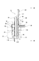
操作軸30は、機枠10及び蓋体60のそれぞれの回転中心孔17,62に遊嵌されており、ベースプレート110及びアームプレート120にそれぞれ形成された支持孔112,122にも遊嵌により挿通されている。また、操作軸30は、そのセレーション35がベースプレート110の外方に突出し、セレーション32がアームプレート120の外方に突出している。なお、セレーション35に取り付けられた操作レバー31には、更に操作ノブ33が取り付けられている。
【0034】
カム状板40は、その回転中心孔42に操作軸30の圧入軸部30aを圧入により固定するようになっており、外周面には上述したロックカム面41、ロック解除カム面44がそれぞれ2つずつ形成されている。更に、カム状板40の外周面には、ロックスプリング70の外側端70bが係止する係止部43が形成されている。
【0035】
ロックスプリング70は、うず巻スプリングによって構成されており、その基部70aが凸部13によって保持され、その外側端70bがカム状板40の係止部43に係止して、カム状板40を図1において反時計方向に回転させるべく該カム状板40に付勢力を付すようになっている。なお、カム状板40は、軸対称の2ヶ所の位置に設けられた係止部43を介して、2つのロックスプリング70からの付勢力を接線方向に効率よく受けるようになっている。
【0036】
アームプレート120は、シートバック160側への取付部121と、うず巻スプリング130の内側部131を保持する保持手段140を有している。
【0037】
この保持手段140は、アームプレート120の回転中心孔122の下部側に設けられており、回転中心孔122を中心とする所定の曲率半径の軌跡に沿って、アームプレート120を半円状に切り起こして形成されている。この切り起こし部141の一側端側に形成された凹部(図示せず)にうず巻スプリング130の内側端132が係止されている。
【0038】
また、うず巻スプリング130の外側端133は、ベースプレート110に設けた係止ピン111に係止されている。そして、このうず巻スプリング130によりアームプレート120は常時フロント(F)方向に回転するように付勢されている。
【0039】
なお、図9において、123は前倒れストッパで、アームプレート120、すなわちシートバック160がフロント(F)方向に回転したとき、ベースプレート110の係止ピン111に前倒れストッパ123が当接し、これによりシートバック160のフロント(F)方向の回転を規制している。また、本実施例に限られるのではなく上記構造とは逆に機枠10にアームプレート120を取り付け、蓋体60をシートクッション150側に取り付けても良い。
【0040】
つぎに、上述した車両用シートリクライニング装置Eの作用、効果等について説明する。
【0041】
車両用シートリクライニング装置Eを組み立てるには、まず機枠10側にカム状板40及びロックスプリング70を設置する。この状態ではロックスプリング70の付勢力により、ロックスプリング70の外側端70bが第1ガイド凸部11Aの摺接面11cに係合しており、カム状板40の係止部43とは係合していない。
【0042】
次に、カム状板40の回転中心孔42に形成したセレーション42aに噛合するセレーションを有するシャフト状の保持具(図示せず)を用いて、カム状板40を時計方向に回転させ、これによってカム状板40の係止部43にロックスプリング70の外側端70bが係合することになり、この状態でロックツース20を機枠10側に設置した上で、機枠10の円形凹部14に蓋体60を嵌合する。即ち、保持具のセレーション部を回転中心孔42に挿入して時計方向に回転した状態では、ロック解除カム面44、被ロック解除カム面26を介してロックツース20が反時計方向に回転し、外歯ギヤ21が仮想上の蓋体60の内歯ギヤ61の位置より半径方向の内側に移動することになる。そこで、機枠10の内周面14aとロックツース20の外歯ギヤ21との間にリム部60aを挿入するようにして、蓋体60を機枠10の円形凹部14に嵌合する。その後、保持具に作用させていた力を抜くことにより、ロックスプリング70の付勢力により、カム状板40を介して、ロックツース20が時計方向に揺動し、外歯ギヤ21が内歯ギヤ61に噛合した状態になる。即ち、ロックツース20は、外歯ギヤ21が内歯ギヤ61に噛合し終わるまで時計方向に揺動する。蓋体60を組み付けた後は、保持具を取り外す。
【0043】
次に、機枠10及び蓋体60の外周部をホルダ80で覆う。これにより、機枠10及び蓋体60は、軸方向に分離されることなく相互に回転可能に支持された状態になる。
【0044】
このようにして、機枠10、ロックツース20、カム状板40、蓋体60、ロックスプリング70、ホルダ80を全て組み立てた後に、セレーション32、4部における回転方向の所定の位置を機枠10の所定の位置に合わせた状態で、操作軸30の圧入軸部30aをカム状板40の回転中心孔42に圧入する。
【0045】
このようにして組立が完成した車両用シートリクライニング装置Eは、シートの左右両側の位置に組み付けられることになる。この組み付けの際に、各操作軸30のセレーション32にシャフト50のセレーション51を嵌合させる。
【0046】
また、運転席の場合には、シートの右側(ドア側)に位置する操作軸30のセレーション34に操作レバー31のセレーション35を嵌合させて、ボルト(図示せず)等により、操作レバー31を操作軸30に固定する。また、助手席の場合には、シートの左側(ドア側)に位置する操作軸30に操作レバー31を取り付ける。
【0047】
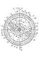
このようにしてシートに組み付けられた車両用シートリクライニング装Eにおいては、通常時は図1に示すように、カム状板40がロックスプリング70の付勢力により反時計方向に回転しているので、ロックカム面41によってロックツース20の被ロックカム面25が押圧され、ロックツース20が軸部16を介して時計方向に揺動し、外歯ギヤ21が蓋体60の内歯ギヤ61に噛合した状態になっている。即ち、シートバック160の回転が阻止された状態になっている。この状態においては、線L1と線L2、線L3と線L4がそれぞれ図1に示すように、ほぼ重なった状態になる。
【0048】
一方、操作レバー31の操作ノブ33を操作して操作軸30を時計方向に回転させると、カム状板40のロックカム面41とロックツース20の被ロックカム面25との係合が解かれると共に、ロック解除カム面44がロックツース20の被ロック解除カム面26を押圧することになる。
【0049】
このため、ロックツース20は、軸部16を中心として反時計方向に揺動し、外歯ギヤ21と蓋体60の内歯ギヤ61との噛合が解かれてロック解除状態となり、蓋体60に取り付けられたアームプレート120,すなわちシートバック160がうず巻スプリング130の付勢力によりフロント(F)方向に回転する。
【0050】
このロック解除状態から再びロック状態に復帰させるには、所望するシートバック160の傾動位置で把持している操作ノブ33を放す操作を行う。そうすると、ロックスプリング70の付勢力によりカム状板40が反時計方向に回転し、これによりロックツース20が時計方向に回転し、その外歯ギヤ21が内歯ギヤ61と噛合してロック状態となる。
【0051】
そして、上記車両用シートリクライニング装置Eによれば、セレーション32、34における回転方向の所定の位置を機枠10における所定の位置に合わせた状態で、操作軸30の圧入軸部30aをカム状板40の回転中心孔42に圧入するようになっているので、機枠10に対する操作軸30の回転方向の角度が一定になる。即ち、カム状板40の回転によりロックツース20の歯21を内歯ギヤ61に噛合し終え、これによりカム状板40が停止した時点で、上述のように回転中心孔42に操作軸30を圧入することにより、ロック状態における操作軸30の回転方向の位置、即ち操作軸30の角度を一定にすることができる。そして、機枠10がシートクッション150側に固定されているので、操作レバー31の延在方向がシートクッション150に対して常に一定になり、見栄えが良くなるという利点がある。
【0052】
また、機枠10をシートクッション150における左右両側の各位置に連結し、蓋体60をシートバック160における左右両側の各位置に連結しているので、シートバック160を左右の各位置で所定の角度に確実かつ安全に保持することができる。
【0053】
更に、左右に位置する操作軸30は機枠10を基準にしてセレーション32の回転方向の位置が一定になるので、それぞれのセレーション32を介して操作軸30にシャフト50を容易に連結することができる。即ち、左右の操作軸30のセレーション32の回転方向の位置、即ち角度がずれることがないので、これらの操作軸30のセレーション32とシャフト50のセレーション51との回転方向の遊びを小さくしても、操作軸30のセレーション32とシャフト50のセレーション51とを容易に嵌合することができる。
【0054】
従って、例えば運転席でいえば、右側の操作レバー31を操作した際の、左右両側の歯21と内歯ギヤ61との噛合及び噛合解除のタイミングのずれやばらつきを小さくすることができる。よって、シートバック160の角度を設定する際のフィーリングが向上するという利点がある。
【0055】
ただし、上述した操作軸30のセレーション32とシャフト50のセレーション51との回転方向の遊びがあまりにも小さくなりすぎると、例えばシートクッション150の左側などの一方の側にベルトアンカなどが取り付けられ、そのベルトアンカから大きな力が作用した場合、シートクッション150の強度メンバー等の弾性変形によりその一方の側の操作軸30が回転して、その回転がシャフト50を介して他方の側の操作軸30に伝わり、同他方の側の歯21と内歯ギヤ61との噛合が解除されてしまうというような不具合を生じることが有り得る。このため、上述した回転方向の遊びは最小限の範囲で設けることが好ましい。しかし、その最小限の範囲の遊びに加えて、従来必要であった組立上の遊びを加わえる必要がないので、シートバック160の角度を設定する際のフィーリングが悪化するのを最小限に抑えることができる。
【0056】
また、ロックツース20が、機枠10に突設された軸部16と2つの円弧状ガイド面11a,11bにより回転可能に支持されているため、衝突等によりシートバック160に作用した負荷がロックツース20に作用しても軸部16と一方の円弧状ガイド面で支持することができ、受け面を大きくできるので負荷による圧壊荷重を高くでき、強度を大幅に向上することができる。
【0057】
一方、ロックツース20が機枠10における周方向に180度離れた位置に配置され、ロックカム面41がカム状板40における回転中心孔42回りに180度離れた位置に配置され、カム状板40は各ロックカム面41を結ぶ線に対して略直交する線上の位置であって回転中心孔42回りに180度離れた位置に被拘束外周面45を有し、機枠10は各ロックツース20の被ロックカム面25を結ぶ線に対して略直交する線上の位置であって周方向に180度離れた位置にガイド部11Aを有し、このガイド部11Aには、各被拘束外周面45に摺接する摺接面11cが形成されているので、カム状板40の回転の自由性及び各被ロックカム面25が設置されている方向へのカム状板40の移動の自由性を損なうことなく、各被ロックカム面25が配置されている方向とは略直交する方向へのカム状板40の移動を防止して、該カム状板40を安定的に保持することができる。
【0058】
そして、カム状板40は各ロックツース20との押圧力のバランスがとれた位置に移動することができるので、各ロックツース20の外歯ギヤ21を内歯ギヤ61に確実に噛合させることができる。しかも、この押圧力のバランスをとるために、カム状板40の例えば回転中心孔にガタを有する操作軸を嵌合するような従来の構成をとる必要がないので、そのガタにより異音が発生したり、この異音を防止するために、部品点数や組立工数が増加したりするのを防止することができる。
【0059】
更に、ガイド部11Aによってカム状板40の位置が安定するので、上述したように、機枠10、蓋体60、ロックツース20、カム状板40等の全体を組み立てた上で、カム状板40の回転中心孔42に操作軸30を圧入するのが容易になるという利点がある。
【0060】
また、各被拘束外周面45がカム状板40の回転中心孔42を中心とする円弧状に形成され、該カム状板40の回転範囲において常にガイド部11Aの摺接面11cに摺接するようになっているので、カム状板40の回転の自由性及びロックツース20が配置されている方向へのカム状板40の移動の自由性をより確実に維持することができるという利点もある。
【0061】
なお、上記実施例では、車両用シートリクライニング装置Eをシートの左右両側に設けるように構成したが、この車両用シートリクライニング装置Eは、シートの一方の側に設けるように構成してもよい。
【0062】
【発明の効果】
請求項1記載の発明においては、ロックツース(20)が機枠(10)における周方向に180度離れた位置に配置され、ロックカム面(41)がカム状板(40)における回転軸回りに180度離れた位置に形成され、カム状板(40)には各ロックカム面(41)を結ぶ線(L1)に対して略直交する線(L2)上の位置であって回転軸回りに180度離れた位置に被拘束外周面(45)を設け、機枠(10)には各ロックツース(20)の被ロックカム面(25)を結ぶ線(L3)に対して略直交する線(L4)上の位置であって周方向に180度離れた位置にガイド部(11A)を設け、このガイド部(11A)には各被拘束外周面(45)に摺接する摺接面(11c)を設けているので、カム状板(40)の回転の自由性及びロックツース(20)が設置されている方向へのカム状板(40)の移動の自由性を確保することができると共に、ロックツース(20)が設けられている方向とは略直交する方向へのカム状板(40)の移動を防止して、カム状板(40)の位置の安定化を図ることができる。
【0063】
即ち、カム状板(40)は各ロックツース(20)との押圧力のバランスがとれた位置に移動することができるので、各ロックツース(20)の歯(21)を内歯ギヤ(61)に確実に噛合させることができる。しかも、この押圧力のバランスをとるために、カム状板(40)の例えば回転中心孔にガタを有する操作軸を嵌合する必要がないので、そのガタによる異音の発生を防止することができると共に、その異音を防止するためのスプリングなどの部品の点数やその部品を組み込むための工数を低減することができる。
【0064】
更に、ガイド部(11A)によってカム状板(40)の位置が安定するので、機枠(10)、蓋体(60)、ロックツース(20)、カム状板(40)等の全体を組み立てた後に、例えばカム状板(40)の回転中心孔に操作軸を圧入により固定することも可能になるという利点がある。
【0065】
また、各被拘束外周面(45)がカム状板(40)の回転軸を中心とする円弧状に形成され、該カム状板(40)の回転範囲において常にガイド部(11A)の摺接面(11c)に摺接するようになっているので、カム状板(40)の回転の自由性及びロックツース(20)が設けられている方向へのカム状板(40)の移動の自由性をより確実に確保することができる。
請求項2記載の発明においては、カム状板(40)が、各非拘束外周面(45)に隣接した180度の間隔、つまり軸対称の2ヶ所の位置に設けられた係止部(43)を介して、ロックスプリング(70)からの付勢力を接線方向に効率よく受けることができる。
【図面の簡単な説明】
【図1】この発明の実施例に係る車両用シートリクライニング装置を示す要部正面視説明図である。
【図2】同車両用シートリクライニング装置を示す図であって、図1のII-II断面説明図である。
【図3】同車両用シートリクライニング装置を示す図であって、図1のIII-III断面説明図である。
【図4】同車両用シートリクライニング装置のロックツースを示す正面視拡大説明図である。
【図5】同車両用シートリクライニング装置を示す図であって、図3の一点鎖線で囲んだ部分の拡大図である。
【図6】同車両用シートリクライニング装置の要部分解斜視説明図である。
【図7】同車両用シートリクライニング装置の正面視説明図である。
【図8】同車両用シートリクライニング装置を示す図であって、図7のVIII-VIII断面説明図である。
【図9】同車両用シートリクライニング装置を示す図であって、図8のIX−IX矢視説明図である。
【符号の説明】
10 機枠
11A 第1ガイド凸部(ガイド部)
11c 摺接面
20 ロックツース
21 外歯ギヤ(歯)
25 被ロックカム面
40 カム状板
41 ロックカム面
45 被拘束外周面
60 蓋体
61 内歯ギヤ
150 シートクッション
160 シートバック
E 車両用シートリクライニング装置
L1、L2、L3、L4 線[0001]
BACKGROUND OF THE INVENTION
The present invention relates to a vehicle seat reclining device for rotatably mounting a seat back serving as a backrest with respect to a seat cushion serving as a seating surface.
[0002]
[Prior art]
Conventionally, as this type of vehicle seat reclining device, for example, one disclosed in Japanese Patent Laid-Open No. 7-136032 is known. In other words, the machine frame attached to the base plate on the seat cushion side and the lid attached to the arm plate on the seat back side are configured to be able to rotate with respect to each other. The mutual rotation between the machine frame and the lid is prevented by meshing with an internal gear formed on the inner peripheral surface of the machine. That is, the lock tooth is moved to the internal gear side by rotating the cam-like plate by a predetermined amount via an operation shaft provided through the machine frame and the lid, and the tooth of the lock tooth and the internal gear It meshes with the mesh. Further, by rotating the cam-like plate in the opposite direction via the operation shaft, the lock tooth is moved away from the internal gear directly or indirectly via the cam-like plate, and the lock tooth and the internal gear are moved. The lock state is released.
[0003]
In addition, the cam-like plate is configured to simultaneously move two lock teeth located 180 degrees apart in the circumferential direction to the internal gear side. For this reason, the cam-like plate has a long hole formed in the central portion so as to be long in the direction in which the lock tooth and the cam-like plate are pressed, and the cam-like plate is camped by the gap between the operation shaft inserted through the long hole. By making the plate-like plate movable along the long hole, the balance of the pressing force between the cam-like plate and the two lock teeth is prevented, and the teeth of the lock tooth and the internal gear are in a half-engaged state. Can be prevented.
[0004]
[Problems to be solved by the invention]
As described above, in the vehicle seat reclining device configured to move the lock tooth in the locking direction and the unlocking direction via the cam-like plate by rotating the operation shaft, the teeth of the lock tooth and the internal gear are A small amount of clearance is provided between the cam plate and the operating shaft to prevent the half-engaged state. This clearance causes the cam plate and the operating shaft to which the operating lever is attached. There is a problem that play occurs in the operation lever, and play of the control lever and abnormal noise occur.
[0005]
Therefore, conventionally, a spring is provided on the operating lever to prevent backlash between the cam-like plate and the operating shaft, thereby preventing abnormal noise. For this reason, there are problems such as an increase in the number of parts and an increase in the number of assembly steps.
[0006]
The present invention has been made to solve the above problems, and provides a vehicle seat reclining device capable of preventing the generation of abnormal noise while maintaining the balance of the pressing force between the cam-like plate and the lock tooth. It is an issue.
[0007]
[Means for Solving the Problems]
In order to solve the above-mentioned problem, the invention according to claim 1 includes a machine casing (10), and is rotatably attached to the machine casing (10), and has an internal gear (61) along the inner peripheral surface. A lock tooth (20) having a lid (60), a tooth (21) attached to the machine frame (10) and meshable with the internal gear (61), and the lock tooth when rotated by a predetermined angle; A lock cam surface (41) for pressing the locked cam surface (25) of (20) to move the lock tooth (20) to the internal gear (61) side and to mesh the tooth (21) with the internal gear (61). And one of the machine frame (10) and the lid (60) is connected to the seat cushion (150) side, and the other is connected to the seat back (160) side. In this state, the teeth (21 of the lock tooth (20) Is engaged with different positions in the internal gear (61) to change the inclination of the seat back (160), and the lock tooth (20) is 180 degrees away in the circumferential direction of the machine frame (10). The lock cam surface (41) is formed at a position 180 degrees away around the rotation axis of the cam plate (40), and the cam plate (40) is provided with each lock cam surface (41). At a position on the line (L2) that is substantially orthogonal to the line (L1) connecting the two and 180 degrees away from the rotation axisArc-shaped around the rotation axisA constrained outer peripheral surface (45) is provided, and the machine frame (10) is positioned on a line (L4) substantially orthogonal to a line (L3) connecting the locked cam surfaces (25) of the lock teeth (20). A guide portion (11A) is provided at a position 180 degrees apart in the circumferential direction, and the guide portion (11A) is in sliding contact with each of the restrained outer peripheral surfaces (45).In addition, the lock tooth (20) is formed in a plane substantially parallel to a line (L3) connecting the locked cam surfaces (25).A sliding contact surface (11c) is provided.
[0008]
The invention according to claim 2 is the invention according to claim 1,A lock spring (70) that urges the lock cam surface (25) in a direction to engage the locked cam surface (25) of the lock tooth (20) is engaged with the outer peripheral surface of the cam plate (40). The locking portions (43) are formed at intervals of 180 degrees adjacent to the respective unconstrained outer peripheral surfaces (45).It is characterized by that.
[0009]
And in invention of Claim 1 comprised as mentioned above, a lock tooth (20) is arrange | positioned in the position 180 degrees away in the circumferential direction in the machine frame (10), and a lock cam surface (41) is a cam-shaped board. A position on the line (L2) that is formed at a position 180 degrees away from the rotation axis in (40) and is substantially orthogonal to the line (L1) connecting each lock cam surface (41) to the cam plate (40). A constrained outer peripheral surface (45) is provided at a position 180 degrees away from the rotation axis, and the machine frame (10) is connected to a line (L3) connecting the locked cam surface (25) of each lock tooth (20). A guide portion (11A) is provided at a position on the substantially orthogonal line (L4) and 180 degrees away in the circumferential direction, and the guide portion (11A) is in sliding contact with each constrained outer peripheral surface (45). Since the sliding contact surface (11c) is provided, the cam plate 40) the freedom of rotation and the freedom of movement of the cam-like plate (40) in the direction in which the lock tooth (20) is installed, and the direction in which the lock tooth (20) is provided. Can prevent the cam plate (40) from moving in a direction substantially orthogonal to stabilize the position of the cam plate (40).
[0010]
That is, since the cam-like plate (40) can move to a position where the pressing force of each lock tooth (20) is balanced, the teeth (21) of each lock tooth (20) are moved to the internal gear (61). Engage reliably. In addition, in order to balance this pressing force, it is not necessary to fit an operating shaft having backlash, for example, in the rotation center hole of the cam-like plate (40), so that generation of abnormal noise due to the backlash can be prevented. In addition, it is possible to reduce the number of parts such as a spring for preventing the noise and the number of steps for incorporating the part.
[0011]
Furthermore, since the position of the cam plate (40) is stabilized by the guide portion (11A), the entire machine frame (10), lid (60), lock tooth (20), cam plate (40) and the like are assembled. There is an advantage that the operation shaft can be fixed by press-fitting into the rotation center hole of the cam-like plate (40) later.
[0012]
Also,Each constrained outer peripheral surface (45) is formed in an arc shape centering on the rotation axis of the cam-like plate (40), and the sliding contact surface (11A) of the guide portion (11A) is always within the rotation range of the cam-like plate (40) 11c), the cam-like plate (40) is more freely rotated and the cam-like plate (40) is more freely moved in the direction in which the lock tooth (20) is provided. Can be secured.
In the second aspect of the present invention, the cam-like plate (40) is provided with locking portions (43) provided at intervals of 180 degrees adjacent to each non-constrained outer peripheral surface (45), that is, at two axially symmetrical positions. ), The urging force from the lock spring (70) can be efficiently received in the tangential direction.
[0013]
DETAILED DESCRIPTION OF THE INVENTION
DESCRIPTION OF THE PREFERRED EMBODIMENTS Embodiments of the present invention will be described below with reference to FIGS.
[0014]
The vehicle seat reclining device E shown in this embodiment is fitted to the inner surface side of the
[0015]
The
[0016]
Further, the
[0017]
An
[0018]
Further, the
[0019]
Further, the
[0020]
Further, the
[0021]
Hereinafter, the above configuration will be described in more detail.
[0022]
The outer surface of the
[0023]
The
[0024]
Further, two first guide
[0025]
The
[0026]
The
[0027]
The first guide
[0028]
The
[0029]
Moreover, the
[0030]
The
[0031]
The
[0032]
Further, the outer
[0033]
The
[0034]
The cam-
[0035]
The
[0036]
The
[0037]
The holding means 140 is provided on the lower side of the
[0038]
Further, the
[0039]
In FIG. 9,
[0040]
Next, functions and effects of the above-described vehicle seat reclining device E will be described.
[0041]
In order to assemble the vehicle seat reclining device E, first, the cam-
[0042]
Next, the cam-shaped
[0043]
Next, the outer periphery of the
[0044]
In this way, after assembling the
[0045]
The vehicle seat reclining device E thus assembled is assembled at positions on the left and right sides of the seat. At the time of this assembly, the
[0046]
In the case of a driver's seat, the
[0047]
In the vehicle seat reclining device E assembled in the seat in this way, the cam-
[0048]
On the other hand, when the
[0049]
Therefore, the
[0050]
In order to return from the unlocked state to the locked state again, an operation of releasing the
[0051]
According to the vehicle seat reclining device E, the press-
[0052]
Further, since the
[0053]
Furthermore, since the
[0054]
Therefore, for example, in the driver's seat, it is possible to reduce a shift or variation in the timing of meshing and meshing release between the
[0055]
However, if the play in the rotational direction between the
[0056]
Further, since the
[0057]
On the other hand, the
[0058]
Since the cam-
[0059]
Further, since the position of the
[0060]
Further, each constrained outer
[0061]
In the above embodiment, the vehicle seat reclining device E is provided on both the left and right sides of the seat. However, the vehicle seat reclining device E may be provided on one side of the seat.
[0062]
【The invention's effect】
In the first aspect of the present invention, the lock tooth (20) is disposed at a position 180 degrees apart in the circumferential direction of the machine frame (10), and the lock cam surface (41) is 180 around the rotation axis of the cam-like plate (40). The cam-like plate (40) is located at a position on a line (L2) substantially perpendicular to the line (L1) connecting the lock cam surfaces (41) to the cam-like plate (40), and 180 degrees around the rotation axis. On the line (L4) substantially orthogonal to the line (L3) connecting the locked cam surface (25) of each lock tooth (20) to the machine frame (10). The guide portion (11A) is provided at a position 180 degrees apart in the circumferential direction, and the guide portion (11A) is provided with a slidable contact surface (11c) that slidably contacts each constrained outer peripheral surface (45). Therefore, the freedom of rotation of the cam plate (40) and the lock The cam in the direction in which the tooth (20) is installed can ensure the freedom of movement of the cam-like plate (40), and the cam is in a direction substantially orthogonal to the direction in which the lock tooth (20) is provided. The movement of the plate-like plate (40) can be prevented, and the position of the cam-like plate (40) can be stabilized.
[0063]
That is, since the cam-like plate (40) can move to a position where the pressing force of each lock tooth (20) is balanced, the teeth (21) of each lock tooth (20) are moved to the internal gear (61). Engage reliably. In addition, in order to balance this pressing force, it is not necessary to fit an operating shaft having backlash, for example, in the rotation center hole of the cam-like plate (40), so that generation of abnormal noise due to the backlash can be prevented. In addition, it is possible to reduce the number of parts such as a spring for preventing the noise and the number of steps for incorporating the part.
[0064]
Furthermore, since the position of the cam plate (40) is stabilized by the guide portion (11A), the entire machine frame (10), lid (60), lock tooth (20), cam plate (40) and the like are assembled. There is an advantage that the operation shaft can be fixed by press-fitting into the rotation center hole of the cam-like plate (40) later.
[0065]
Also,Each constrained outer peripheral surface (45) is formed in an arc shape centering on the rotation axis of the cam-like plate (40), and the sliding contact surface (11A) of the guide portion (11A) is always within the rotation range of the cam-like plate (40) 11c), the cam-like plate (40) is more freely rotated and the cam-like plate (40) is more freely moved in the direction in which the lock tooth (20) is provided. Can be secured.
In the second aspect of the present invention, the cam-like plate (40) is provided with locking portions (43) provided at intervals of 180 degrees adjacent to each non-constrained outer peripheral surface (45), that is, at two axially symmetrical positions. ), The urging force from the lock spring (70) can be efficiently received in the tangential direction.
[Brief description of the drawings]
FIG. 1 is an explanatory front view of a main part of a vehicle seat reclining device according to an embodiment of the present invention.
FIG. 2 is a view showing the vehicle seat reclining device, and is a cross-sectional view taken along the line II-II in FIG. 1;
3 is a view showing the vehicle seat reclining device, and is an explanatory view taken along the line III-III in FIG. 1; FIG.
FIG. 4 is a front view enlarged explanatory view showing a lock tooth of the vehicle seat reclining device.
5 is a view showing the vehicle seat reclining device, and is an enlarged view of a portion surrounded by a one-dot chain line in FIG. 3;
FIG. 6 is an exploded perspective view of a main part of the vehicle seat reclining device.
FIG. 7 is a front view explanatory view of the vehicle seat reclining device.
8 is a view showing the vehicle seat reclining device, and is a cross-sectional explanatory view taken along the line VIII-VIII in FIG. 7;
9 is a view showing the vehicle seat reclining device, and is an explanatory view taken along arrows IX-IX in FIG. 8;
[Explanation of symbols]
10 Airframe
11A 1st guide convex part (guide part)
11c Sliding surface
20 Rock Tooth
21 External gear (tooth)
25 Locked cam surface
40 Cam plate
41 Lock cam surface
45 Constrained outer peripheral surface
60 lid
61 Internal gear
150 seat cushion
160 Seat back
E Vehicle seat reclining device
L1, L2, L3, L4 lines
Claims (2)
前記機枠(10)及び蓋体(60)の一方をシートクッション(150)側に連結し、他方をシートバック(160)側に連結した状態で、前記ロックツース(20)の歯(21)を内歯ギヤ(61)における異なる位置に噛合させることによりシートバック(160)の傾きを変更するようになっており、
前記ロックツース(20)は、機枠(10)における周方向に180度離れた位置に配置され、
前記ロックカム面(41)は、カム状板(40)における回転軸回りに180度離れた位置に形成され、
前記カム状板(40)には、各ロックカム面(41)を結ぶ線(L1)に対して略直交する線(L2)上の位置であって回転軸回りに180度離れた位置に回転軸を中心とする円弧状の被拘束外周面(45)を設け、
前記機枠(10)には、各ロックツース(20)の被ロックカム面(25)を結ぶ線(L3)に対して略直交する線(L4)上の位置であって周方向に180度離れた位置にガイド部(11A)を設け、
このガイド部(11A)には、前記各被拘束外周面(45)に摺接するとともに前記各ロックツース(20)の前記被ロックカム面(25)を結ぶ線(L3)に対して略平行な平面状に形成された摺接面(11c)を設けていることを特徴とする車両用シートリクライニング装置。A machine frame (10), a lid (60) rotatably attached to the machine frame (10) and having an internal gear (61) along an inner peripheral surface, and attached to the machine frame (10) The lock tooth (20) having teeth (21) that can mesh with the internal gear (61), and the lock tooth (20) of the lock tooth (20) when pressed by a predetermined angle, press the cam surface (25) of the lock tooth (20). A rotary cam-like plate (40) having a lock cam surface (41) for moving (20) toward the internal gear (61) and meshing the teeth (21) with the internal gear (61);
With one of the machine frame (10) and lid (60) connected to the seat cushion (150) side and the other connected to the seat back (160) side, the teeth (21) of the lock tooth (20) are The inclination of the seat back (160) is changed by meshing with different positions in the internal gear (61),
The lock tooth (20) is arranged at a position 180 degrees apart in the circumferential direction of the machine casing (10),
The lock cam surface (41) is formed at a position 180 degrees around the rotation axis of the cam plate (40),
The cam-like plate (40) has a rotational axis at a position on a line (L2) substantially orthogonal to the line (L1) connecting the lock cam surfaces (41) and 180 degrees away from the rotational axis. An arc-shaped restrained outer peripheral surface (45) centered on
The machine frame (10) is located at a position on a line (L4) substantially orthogonal to a line (L3) connecting the locked cam surfaces (25) of the respective lock teeth (20), and is 180 degrees apart in the circumferential direction. A guide part (11A) is provided at the position,
The guide portion (11A) has a planar shape that is in slidable contact with each of the restrained outer peripheral surfaces (45) and substantially parallel to a line (L3) connecting the locked cam surfaces (25) of the lock teeth (20). The vehicle seat reclining device is provided with a slidable contact surface (11c).
Priority Applications (6)
| Application Number | Priority Date | Filing Date | Title |
|---|---|---|---|
| JP2001101177A JP3961779B2 (en) | 2001-03-30 | 2001-03-30 | Vehicle seat reclining device |
| US10/091,848 US6648414B2 (en) | 2001-03-30 | 2002-03-06 | Reclining device and method for manufacturing the same |
| CA002374798A CA2374798C (en) | 2001-03-30 | 2002-03-06 | Reclining device and method for manufacturing the same |
| KR10-2002-0016265A KR100458859B1 (en) | 2001-03-30 | 2002-03-26 | Reclining device and method for manufacturing the same |
| EP02252228A EP1245435B1 (en) | 2001-03-30 | 2002-03-27 | Reclining device and method for manufacturing the same |
| DE60230696T DE60230696D1 (en) | 2001-03-30 | 2002-03-27 | Tilt adjustment device and its production method |
Applications Claiming Priority (1)
| Application Number | Priority Date | Filing Date | Title |
|---|---|---|---|
| JP2001101177A JP3961779B2 (en) | 2001-03-30 | 2001-03-30 | Vehicle seat reclining device |
Publications (2)
| Publication Number | Publication Date |
|---|---|
| JP2002291563A JP2002291563A (en) | 2002-10-08 |
| JP3961779B2 true JP3961779B2 (en) | 2007-08-22 |
Family
ID=18954535
Family Applications (1)
| Application Number | Title | Priority Date | Filing Date |
|---|---|---|---|
| JP2001101177A Expired - Lifetime JP3961779B2 (en) | 2001-03-30 | 2001-03-30 | Vehicle seat reclining device |
Country Status (1)
| Country | Link |
|---|---|
| JP (1) | JP3961779B2 (en) |
Families Citing this family (5)
| Publication number | Priority date | Publication date | Assignee | Title |
|---|---|---|---|---|
| KR100472186B1 (en) * | 2002-05-31 | 2005-03-08 | 주식회사 윤 영 | High-rigidity type recliner for vehicle |
| US6854802B2 (en) | 2002-10-01 | 2005-02-15 | Fujikiko Kabushiki Kaisha | Seat recliner for vehicle |
| JP4185750B2 (en) * | 2002-10-01 | 2008-11-26 | 富士機工株式会社 | Vehicle seat reclining device |
| JP4653523B2 (en) * | 2005-03-09 | 2011-03-16 | 富士機工株式会社 | Vehicle seat reclining device |
| CN100509475C (en) * | 2006-01-31 | 2009-07-08 | 富士机工株式会社 | Vehicle seat reclining device |
-
2001
- 2001-03-30 JP JP2001101177A patent/JP3961779B2/en not_active Expired - Lifetime
Also Published As
| Publication number | Publication date |
|---|---|
| JP2002291563A (en) | 2002-10-08 |
Similar Documents
| Publication | Publication Date | Title |
|---|---|---|
| JP4185750B2 (en) | Vehicle seat reclining device | |
| US6039400A (en) | Seat reclining device | |
| KR100458859B1 (en) | Reclining device and method for manufacturing the same | |
| JP3540952B2 (en) | Adjustment and fixing devices for vehicle seat devices | |
| WO2001012462A1 (en) | Rotary-cam type reclining device | |
| WO2006080446A1 (en) | Reclining adjuster | |
| JP3961779B2 (en) | Vehicle seat reclining device | |
| JP2002102000A (en) | Seat reclining device of vehicule | |
| JP4766765B2 (en) | Vehicle seat reclining device and manufacturing method thereof | |
| JP3990872B2 (en) | Vehicle seat reclining device | |
| JP4185819B2 (en) | Vehicle seat reclining device | |
| JP3762188B2 (en) | Reclining device | |
| JP3628553B2 (en) | Vehicle seat reclining device | |
| JP2000333755A (en) | Reclining device for seat for vehicle | |
| JP2002010851A (en) | Vehicle seat reclining device | |
| JP2002010848A (en) | Vehicle seat reclining device | |
| JP2000189267A (en) | Recliner for vehicle seat | |
| JP4255811B2 (en) | Reclining device | |
| JP3989283B2 (en) | Reclining mechanism | |
| JP2002010847A (en) | Vehicle seat reclining device | |
| JP4316924B2 (en) | Bilateral reclining device | |
| JP3773996B2 (en) | Reclining device | |
| JP2003325260A (en) | Both-side reclining device | |
| JP2002010849A (en) | Vehicle seat reclining device | |
| JP2002010850A (en) | Vehicle seat reclining device |
Legal Events
| Date | Code | Title | Description |
|---|---|---|---|
| A621 | Written request for application examination |
Free format text: JAPANESE INTERMEDIATE CODE: A621 Effective date: 20041118 |
|
| A977 | Report on retrieval |
Free format text: JAPANESE INTERMEDIATE CODE: A971007 Effective date: 20061214 |
|
| A131 | Notification of reasons for refusal |
Free format text: JAPANESE INTERMEDIATE CODE: A131 Effective date: 20061219 |
|
| A521 | Written amendment |
Free format text: JAPANESE INTERMEDIATE CODE: A523 Effective date: 20070216 |
|
| TRDD | Decision of grant or rejection written | ||
| A01 | Written decision to grant a patent or to grant a registration (utility model) |
Free format text: JAPANESE INTERMEDIATE CODE: A01 Effective date: 20070508 |
|
| A61 | First payment of annual fees (during grant procedure) |
Free format text: JAPANESE INTERMEDIATE CODE: A61 Effective date: 20070517 |
|
| R150 | Certificate of patent or registration of utility model |
Free format text: JAPANESE INTERMEDIATE CODE: R150 Ref document number: 3961779 Country of ref document: JP Free format text: JAPANESE INTERMEDIATE CODE: R150 |
|
| FPAY | Renewal fee payment (event date is renewal date of database) |
Free format text: PAYMENT UNTIL: 20100525 Year of fee payment: 3 |
|
| FPAY | Renewal fee payment (event date is renewal date of database) |
Free format text: PAYMENT UNTIL: 20110525 Year of fee payment: 4 |
|
| R250 | Receipt of annual fees |
Free format text: JAPANESE INTERMEDIATE CODE: R250 |
|
| FPAY | Renewal fee payment (event date is renewal date of database) |
Free format text: PAYMENT UNTIL: 20120525 Year of fee payment: 5 |
|
| R250 | Receipt of annual fees |
Free format text: JAPANESE INTERMEDIATE CODE: R250 |
|
| FPAY | Renewal fee payment (event date is renewal date of database) |
Free format text: PAYMENT UNTIL: 20130525 Year of fee payment: 6 |
|
| R250 | Receipt of annual fees |
Free format text: JAPANESE INTERMEDIATE CODE: R250 |
|
| FPAY | Renewal fee payment (event date is renewal date of database) |
Free format text: PAYMENT UNTIL: 20130525 Year of fee payment: 6 |
|
| FPAY | Renewal fee payment (event date is renewal date of database) |
Free format text: PAYMENT UNTIL: 20140525 Year of fee payment: 7 |
|
| R250 | Receipt of annual fees |
Free format text: JAPANESE INTERMEDIATE CODE: R250 |
|
| R250 | Receipt of annual fees |
Free format text: JAPANESE INTERMEDIATE CODE: R250 |
|
| R250 | Receipt of annual fees |
Free format text: JAPANESE INTERMEDIATE CODE: R250 |
|
| R250 | Receipt of annual fees |
Free format text: JAPANESE INTERMEDIATE CODE: R250 |
|
| R250 | Receipt of annual fees |
Free format text: JAPANESE INTERMEDIATE CODE: R250 |
|
| S111 | Request for change of ownership or part of ownership |
Free format text: JAPANESE INTERMEDIATE CODE: R313111 |
|
| R371 | Transfer withdrawn |
Free format text: JAPANESE INTERMEDIATE CODE: R371 |
|
| S111 | Request for change of ownership or part of ownership |
Free format text: JAPANESE INTERMEDIATE CODE: R313111 |
|
| R350 | Written notification of registration of transfer |
Free format text: JAPANESE INTERMEDIATE CODE: R350 |
|
| R250 | Receipt of annual fees |
Free format text: JAPANESE INTERMEDIATE CODE: R250 |
|
| R250 | Receipt of annual fees |
Free format text: JAPANESE INTERMEDIATE CODE: R250 |
|
| R250 | Receipt of annual fees |
Free format text: JAPANESE INTERMEDIATE CODE: R250 |
|
| EXPY | Cancellation because of completion of term |