JP3951120B2 - Simple box - Google Patents
Simple box Download PDFInfo
- Publication number
- JP3951120B2 JP3951120B2 JP2002245792A JP2002245792A JP3951120B2 JP 3951120 B2 JP3951120 B2 JP 3951120B2 JP 2002245792 A JP2002245792 A JP 2002245792A JP 2002245792 A JP2002245792 A JP 2002245792A JP 3951120 B2 JP3951120 B2 JP 3951120B2
- Authority
- JP
- Japan
- Prior art keywords
- top surface
- pair
- flaps
- flap
- box
- Prior art date
- Legal status (The legal status is an assumption and is not a legal conclusion. Google has not performed a legal analysis and makes no representation as to the accuracy of the status listed.)
- Expired - Lifetime
Links
Images


Description
【0001】
【発明の属する技術分野】
本発明は、主として生鮮野菜や果実、或いは花卉などの農産物や園芸品を運搬するのに有用で、天面を閉じたときに天面中央部に通気用開口が形成される箱に関するもので、特に封緘資材を使用しない箱天面の封緘機構に関するものである。
【0002】
【従来の技術】
従来、生鮮野菜や果実或いは花卉などを箱詰めして出荷する場合、一度に多数個が出荷されるので組立てが容易なJIS−Z1507の0201形式(旧A−1形)の段ボール箱が多用されている。
この箱は、長方形状の4側板を一方向に連接し、その4側板の上下に箱の底面及び天面を封鎖するためのフラップを連接してなるほぼ直方体形状の箱である。まず、連接した4枚の側板を角筒状に連結し、内フラップおよび外フラップを折り線で箱の内側に折り曲げ、天面内外各フラップにより開口を設けるようにして閉じ、内外フラップの重なった部分をステッチやステープルと呼ばれる針のような金具Sを打ち込むか、あるいは、底面の両外フラップをまたがるように糊で接着して封緘していた。さらに箱に収納物を収納した後、箱の天面を閉じるときは、図19のように天面内外フラップの重なった部分を主としてステッチ金具Sにより、天面の四隅を止めて出荷していた。
【0003】
【発明が解決しようとする課題】
しかし、段ボール箱を使用する農産物の生産者からは、ステッチ金具等の封緘副資材を使用せずに、組立て作業が容易にできること及び組立てコストの低減化、組立て作業の安全性向上など求められている。また流通、小売業者などからは、使用後の処理に伴う環境問題の解決、廃棄作業の軽減化等を要望されている。
ところが、前述のステッチ方式による封緘の都度、ステッチとステッチ打込みマシンを用意する必要があるが、ステッチ打ち込みマシンは、重くて力を要するので非力の人間には取り扱いが大変であり、労力、時間がかかり、コストが嵩む問題がある。また、商品を取り出すときあるいは検品作業時にけがをする危険性を有している。
また、使用済みの箱を廃棄処分する場合、金属であるステッチが混入したままであると、ダンボールなどの紙類と一緒に焼却処分することができない。分解ゴミ減量のため使用済みの箱を古紙として再利用する場合にあっても、ステッチが不純物となるので分別し、除去する作業が必要であり、処理コストが嵩む問題がある。
さらに、生鮮野菜などの農産品の輸送箱は、一般に、品物を収納後流通の過程において、箱を開いて検品と呼ばれる収納物の異常の有無等の検査を行う。検品後、箱を閉じて再封緘して運搬に供する。しかしステッチにより天面の四隅を止めている従来の箱では検品時の開封が容易でなく、包装箱天面のフラップを損傷させ若しくは外観を損なうことが多く、そのうえ再封時には改めてステッチあるいはテープを用いて再封を必要とするという欠点を有し、フラップの損傷時には再封緘が困難となる。
【0004】
そこで、本発明は、上記の問題点を解決し、ステッチ等の封緘副資材の使用を廃止して箱組立時の作業、量販店での陳列時の開封作業、使用後の解体作業などでの安全性と簡便性の要求に応え、使用後の環境問題も解決すると同時に、検品作業等に備えて開封を容易にし、かつ確実な再封緘機能を有し、さらに輸送荷役中に箱詰めした品物が蒸れないように通気性を有した簡易封緘箱を提供するものである。
【0005】
【課題を解決するための手段】
上記課題を解決するために本発明の箱は、次のような手段を採用した。すなわち本発明の第1は、連接する4側面の上端にそれぞれ相対向して内側に折り込まれる一対の天面内フラップと、相対向して該天面内フラップの外側に折り込まれる一対の天面外フラップとが設けられ、前記一対の天面内フラップと一対の天面外フラップとが折り込まれた状態で箱天面に開口が形成される収納箱において、
前記一対の天面内フラップには、天面内フラップの先端から中央部にかけて一対の係合切込を設け、
前記天面内フラップに設けられた一対の係合切込の内側に、該天面内フラップの中央部から側面に連接する折線にかけて、ハの字状の一対の切込を設け、かつ、ハの字の一対の切込の下端部と一対の係合切込の下端部とを結ぶ罫線を設けることで、天面を封緘する際に、天面内フラップが湾曲変形しやすくし、
一方、前記一対の天面外フラップには、先端左右両隅部近傍に、前記天面内フラップの係合切込にかみ合う係合部を設け、
前記天面外フラップに設けられた一対の係合部が、天面外フラップの先端左右両端部をL字状に切り取って形成された切欠き状で、
天面封緘時、天面内フラップの先端部を引き上げることで、天面内フラップのハの字状切込および罫線に沿って天面内フラップの中央部が湾曲し、該係合切込と係合部が係合して内外両フラップがロックされるようにしたものである。
【0006】
本発明の第2は、連接する 4 側面の上端にそれぞれ相対向して内側に折り込まれる一対の天面内フラップと、相対向して該天面内フラップの外側に折り込まれる一対の天面外フラップとが設けられ、前記一対の天面内フラップと一対の天面外フラップとが折り込まれた状態で箱天面に開口が形成される収納箱において、
前記一対の天面内フラップには、天面内フラップの先端から中央部にかけて一対の係合切込を設け、
前記天面内フラップに設けられた一対の係合切込の内側に、該天面内フラップの中央部から側面に連接する折線にかけて、ハの字状の一対の切込を設け、かつ、ハの字の一対の切込の下端部と一対の係合切込の下端部とを結ぶ罫線を設けることで、天面を封緘する際に、天面内フラップが湾曲変形しやすくし、
一方、前記一対の天面外フラップには、先端左右両隅部近傍に、前記天面内フラップの係合切込にかみ合う係合部を設け、
前記天面外フラップに設けられた一対の係合部が、天面外フラップ先端から中央部に向って切込み溝状に切り込まれ、
天面封緘時、天面内フラップの先端部を引き上げることで、天面内フラップのハの字状切込および罫線に沿って天面内フラップの中央部が湾曲し、該係合切込と係合部が係合して内外両フラップがロックされることを特徴とする。
【0010】
【発明の実施の形態】
次に、本発明の実施の形態を図面に基づき説明する。
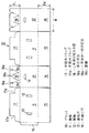
図1は、第1の実施例を示す封緘箱を構成するための組み立て前のブランクシート(以下、ブランクと称する)を示すものであり、このブランク10は、一例としてほぼ長方形をなす1枚の段ボールシートより形成されている。また材料として段ボールに代えて板紙により形成することも可能である。
【0011】
本実施の形態に示す箱は、ブランク10の中央部に、箱の対向する各側面のうち長さ方向の面(長さ面)を構成する一対の側板11、11と、幅方向の面(幅面)を構成する一対の側板12、12を、交互に折線を介し一方向に連接している。前記側板11、11には、通気性を確保するための通気穴13が開設され、また前記側板12、12の中央部に手掛け穴14が設けられている。長さ面を構成する一対の側板11、11は、その下端縁に底板15、15を連接し、幅面を構成する一対の側板12、12は、その下端縁に底フラップ16、16を連接している。
また、前記一対の側板11、11の上端縁には天面外フラップ17、17を、側板12、12の上端縁には天面内フラップ18、18を連接している。符号19は、側板11の端部に連接した連結用の糊代である。
【0012】
本発明において天面外内両フラップ17と18の長さ方向の寸法F1は、箱の幅面を構成する側板12の幅方向寸法Wの1/2よりも短い長さに形成されている。そのため、箱の組み立て時に、天面内外フラップ17、18を重ね合せて箱の天面を封緘するとき、箱天面中央に換気に好適な開口20が形成される(図4参照)。
底板と底フラップ15と16はほぼ矩形に形成され、その長さ方向の寸法F2は、箱の幅面を構成する側板12の幅方向寸法Wの1/2の長さとほぼ等しく、底板と底フラップ15、16を折り畳み、箱の底面を組み立てたとき、底板15、15の先端部分が突合せとなり、底面全面が閉塞される。
【0013】
天面外フラップ17及び天面内フラップ18に、次のような構成をもつ天蓋のロック機構が形成されている。すなわち、天面内フラップ18の先端から中央部にかけて、左右一対の係合切込18a、18aを設け、また、該天面内フラップ18が側面12に連接する折線に近接させて、該折線に向かってハの字状の一対の切込18b、18bを設けている。さらに、この両切込18bの連接折線側の端と、前記係合切込18aの下端部とをそれぞれ結ぶ罫線18cを設けている。この切込18bおよび罫線18cは、天面を封緘する際に、天面内フラップ18が湾曲変形しやすいように設けたものである。ハの字形の一対の切込18bは、ブランク10の紙厚を完全に貫通する切込みまたは紙厚の約半分程度まで切込んだハーフカットの直線などが使用できる。一方、罫線18cは、ブランク10の紙厚の半分程度まで切り込んだハーフカットの直線または断続線などを用いることができる。
一方、天面外フラップ17は先端の左右両隅部をL字状に切り取った切欠き部17aを形成している。
【0014】
このような構成を有するブランク10を組み立てるには、4枚の側板11、12、11、12を順次折り曲げ、糊代19を反対側の側板12に貼着し、角筒状に連結する。使用するまで、扁平に折り畳んだ状態で保管しておくことができる。使用に際して、4側板を角筒状に引き起こし、底フラップ16、16の外側に底面板15、15を折り重ねて、底フラップ16と底板15とをホットメルトなどを使用して適宜底面を封緘する。底面を封緘した後、農産物を箱内に納める。
【0015】
箱詰め作業が完了した後、次のようにして、箱天面を封緘する。
まず天面内フラップ18を、側板12の連接折線より内側に折り曲げる。次に、天面外フラップ17を側板11の連接折線より内側に折り曲げ、天面内フラップ18の外側に折り重ねる(図2、3参照)。
次に、片方の手で両天面外フラップ17を押さえ、もう一方の手を天面の開口20に挿入して、天面内フラップ18の先端部分を持ち引き上げる。このとき、押さえる手は、なるべく天面内フラップ18の先端に近い天面外フラップ17上に置き、上から押さえ固定しながら天面内フラップ18を引き上げる。
天面内フラップ18の先端を引き上げると、図4に示すように、この天面内フラップ18は、ハの字状切込18bおよび罫線18cに沿って中央部が湾曲して、天面内フラップ18の両端は、天面外フラップ17の両端切欠部分を通過し、該天面外フラップ17の上側に引き上げられて、係合切込18aにL字状の切り欠き部17aが噛み合うこととなる(図4と5参照)。
ここで、天面内フラップ18にかけていた引き上げ力を解除すると、内フラップ18は、素材の持つ復元力により、元の形状に戻ろうとして自然に下降する。これによりL字状の切り欠き部17aと係合切込18aにさらに深く嵌合し、天面内フラップ18と天面外フラップ17とには、開きを防止する互いに逆方向の力が働くので、図11のように天面をステッチで止めて封緘した場合と同様に、内外フラップの開きを防止する作用を奏する。
【0016】
従って本発明の箱は、天面封緘時、天面内フラップ18の先端部を引き上げるだけで、天面内フラップ18と天面外フラップ17が互いに係止されるものである。
ところで、一般的に用いられる差込ロック式の封緘構造においては、通常、天面外フラップに設けられた係止部材を、天面内フラップに設けられた係止孔や係止溝に差し込み封緘するものである。また、一般的な他の封緘構造としては、押下げロック式の封緘構造があるが、こちらは、天面外フラップと内フラップを共に内側に押し込むことによって、両フラップに設けられた係止部を係合させて封緘するものである。
本発明は、上記のような天面封緘構造とは異なり、封緘時に、天面フラップや、天面フラップに設けられた係止部材が、天面よりも下方である箱の内側に向かって押し下げられたり、差し込まれたりすることがない。
すなわち、箱内部がすでに収容した内容物で完全に満たされている場合や、内容物が天面よりも盛り上がって収納されている場合においても、問題なく封緘作業を行うことができるばかりでなく、封緘時に内容物がフラップや係止部材が当たることによって傷つけたりする恐れが全く無い。従って、農産物や園芸品などの傷つき易い内容物を収納するに特に適している。さらに、引き上げるという一挙動に極めて簡単な動作によって、確実にロックすることが可能であり、作業者が非力であっても、問題なく封緘作業を行うことが可能である。
また、このような簡便な構成であって封緘作業も容易でありながら、一旦封緘された天面は、輸送中、荷役中に与えられた振動や傾き等によって、容易に開くことなく、完全に固定されるものである。
【0017】
また、箱天面を開封するときは、天面の開口20より手を入れて、天面内フラップ18、18を強制的に外側へ引き上げると、天面内フラップ18は側面12との連接折線を支点に回転すると同時に、天面外フラップ17を上方に押し上げ、係合部17aと係合切込18aとの嵌合が外れるので、容易に開封することができる。
また、開封した天面を再度封緘することも当然容易であって、検品時等に一時的な開封、封緘作業の繰返しにも適する構造である。
【0018】
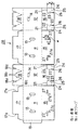
図6は、本発明の別の実施例である段ボール箱の組立て前のブランクを示すものである。本実施例に示す箱も、長さ方向の面(長さ面)を構成する一対の側板11、11と、幅方向の面(幅面)を構成する一対の側板12、12を、交互に、折線を介し一方向に連接する。なお、前記側板11、11には、通気性を確保するための通気穴13が開設され、また前記側板12、12の中央部に手掛け穴14が設けられている。長さ面を構成する一対の側板11、11は、その下端縁に底板15、15を連接し、幅面を構成する一対の側板12、12は、その下端縁に底フラップ16、16を連接している。また、前記一対の側板11、11の上端縁には天面外フラップ17、17を、側板12、12の上端縁には天面内フラップ18、18を連接している。符号19は、側板11の端部に連接した連結用の糊代である。底板と底フラップ15と16はほぼ矩形に形成され、その長さ方向の寸法は、箱の幅面を構成する側板12の幅方向寸法Wの1/2の長さとほぼ等しく、底板と底フラップ15、16を折り畳み、箱の底面を組み立てたとき、底板15、15の先端部分が突合せとなり、底面全面が閉塞される。天面外フラップ17及び天面内フラップ18は、第1の実施例と同様の天蓋のロック機構が形成され、その作用も同様であるので説明は省略する。以下、異なる点につき説明する。
【0019】
前記底板15及び底フラップ16に、次のような構成をもつ底面のロック機構が形成されている。
まず、底フラップ16について説明する。該底フラップ16には左右両側縁のほぼ中央部からそれぞれ反対側の側縁の方向に延びる一対の切込線21、21を設け、その各切込線21の終端部21aを起点とし、底フラップ16の先端部(下縁)に向かって延びる左右一対の折り目(罫線)22、22を設けることで、底フラップ16の両側に差込片23が形成されている。この差込片23の下部には、前記切込線21と平行な折り目(罫線)25と、折り目22と一直線状をなす切り溝26を設けることで、差込ロック片24が形成される。この差込ロック片24は、折り目25を介して、差込片本体23側に折り曲げ可能になっている。
【0020】
なお、底板15には、前記の差込片23に対応して、左右一対の鈎形をした係合穴27を設けている。この鈎形係合穴27の長さAは、差込片本体23の長さXよりも若干長く、鈎部27aの長さBは、差込ロック片24の長さYより若干長く形成されている。
【0021】
このように構成したブランク28は、糊代19と側板12とを貼着して、胴部を扁平に折り畳んだ状態で保管しておき、底面の組立てに際しては、4枚の側板11、12、11、12を角筒状に起こして使用する。
【0022】
次に、この実施例の箱の底面ロック方法を説明する。まず、底フラップ16が底板15の外側にくるように重ね合わせる。すなわち、底板15、15を内側に折り曲げてから(図7)、底フラップ16、16の差込片23を折り目22を介して直角に折り曲げ、更に差込ロック片24を90度内側に折り曲げる。この状態で、底フラップ16を側板12との連接折線で折り曲げる。図7に示すように、差込片23を底フラップ16に対し直角に折り曲げ、さらに差込ロック片24を折り目25にから直角に曲げる。つぎ、底フラップ16を底板15の上に折り重ねると同時に、差込片23を鈎形係合穴27に、また、差込ロック片24を鈎部27aに挿入する。底フラップ16と底板15とが完全に重なると、差込片23と、差込ロック片24は箱の内側に完全に入りこむと同時に、差込ロック片24は、その折り目25から素材(段ボール)自らの復元力により反発して広がることとなる。その結果、差込片23は、差込ロック片24により係合穴27内面(箱の内側)に係止される。
したがって、箱内に農産物を入れるときに、農産物が当たって差込片23が押し下げられ、係合穴27から差込片23が抜けるようなことがない。また箱内に詰め込んだ、農産物に押されて差込片23と、差込ロック片24は倒伏することにより抜けにくくなる。(図8参照)。
【0023】
このように箱内に野菜等の農産物を収容したとき、その重みにより底板15および底フラップ16が押し下げられ撓んでも、差込ロック片24が底面を確実にロックするため、底板と底フラップの重ね合せ部をステッチでジョイントして底面を閉じた場合と同様に、箱の底抜けを完全に防止できる。
【0024】
なお、使用後に底面を解体するときは、差込ロック片24を差込片23に折り重ね、差込片23を底板からから垂直に引き起こし、差込片23を係合穴27から抜けば、ロックが外れて底面が開き、容易に解体することができる。
【0025】
図9は、本発明の第3の実施例の段ボールブランクを示すものである。本実施例に示す箱も、長さ方向の面(長さ面)を構成する一対の側板31、31と、幅方向の面(幅面)を構成する一対の側板32、32を、交互に折線を介し一方向に連接し、前記側板32、32の中央部に手掛け穴34が設けられている。長さ面を構成する一対の側板31、31は、その下端縁に底板35、35を連接し、幅面を構成する一対の側板32、32は、その下端縁に底フラップ36、36を連接している。また、前記一対の側板31、31の上端縁には天面外フラップ37、37を、側板32、32の上端縁には天面内フラップ38、38を連接している。符号39は、側板31の端部に連接した連結用の糊代である。
また、天面外内両フラップ37、38の長さ寸法F1は、第1および第2の実施例と同様、箱の幅面を構成する側板の幅方向寸法Wの1/2よりも短い長さに形成されているため、箱の組み立て時に、箱天面に開口40が形成される。一方、矩形に形成された底板及び底フラップ35、36は、その長さ寸法F2は、幅面を構成する側板の幅方向寸法Wの1/2にほぼ等しく、底面を組み立てたときに底板が突合せになり底面全面を閉止する。
【0026】
本実施例の天面外フラップ37及び天面内フラップ38に、次のような構成をもつ天面ロック機構が形成されている。すなわち、天面内フラップ38の左右両端よりに、該内フラップ38の先端から中央部にかけて切り込まれた、外側に傾斜する溝状の係合切込38a、38aを設ける。また、前記天面内フラップに設けられた一対の係合切込38a、38aの内側に、該天面内フラップの中央部から側面32に連接する折線にかけて、ハの字状の一対の切込38b、38bをそれぞれ設け、かつハの字状切込38bの連接折線側の端と係合切込38aの下端を結ぶ罫線38cを設ける。この罫線38cはブランク板厚の半分程度に切込を入れたハーフカット、あるいは、断続的なカットでも良い。
一方、天面外フラップ37には、先端の左右両隅部近傍に、フラップの先端から中央部にかけて傾斜した係合部37a、37aを切り込み溝状に形成する。
【0027】
このような構成を有するブランク30を組み立てるには4枚の側板31、32、31、32を順次折り曲げ、糊代39を反対側の側板32に貼着し、角筒状に連結する。使用するまでは、扁平に折り畳んだ状態で保管しておくことができる。使用に際し、側板を角筒状に引き起こし、底フラップ36、36を折り曲げ、さらにその外側に底板35、35を折り重ねて糊付け、または粘着テープで貼着して底面を組み立てる。
【0028】
箱の底面を組み立てた後、箱を正立させ、上面の開口部より箱内に野菜などを収容する。続いて天面を封緘するために、天面内フラップ38を側板32と連接する折線で箱の内側に、側板32に対し90度折り曲げる(図10参照)。次に、天面外フラップ37を側板31との連接折線部で内側に90度曲げて、天面内フラップ38の上に重ねる(図11参照)。
次に、ロックしたい箇所の天面外フラップ37を押さえ固定しながら、天面の開口40より手を挿入し、天面内フラップ38の中央部を握って上方に引き上げる。すると、天面内フラップ38のハの字状切込38bおよび罫線38cに沿って天面内フラップ38の中央が湾曲して、天面内フラップ38と天面外フラップ37のそれぞれに設けた係合切込38aと係合部37aとが嵌合する。そこで、天面内フラップ38を引き上げる力を解除すると、素材の持つ反発力により、内フラップ38は元に戻ろうとし、係合切込38aと係合部37aはより深く嵌合する。その結果、天面内フラップ38と天面外フラップ37とは互いに上下からかみ合い、固定する(図12参照)。
この場合、天面内フラップ38と天面外フラップ37とは、互いのフラップの開きを防止する反発力(逆方向に押さえる力)が働くので、天面の内外フラップの重ね合せ部(天面の四隅)をステッチで止めて封緘した場合と同様に、内外フラップの開きを防止する作用を奏し、天面のフラップがロックされる(図13参照)。
【0029】
このように、本実施例の箱においても、第1、第2の実施例と同様、天面の封緘時に天面内フラップを引き上げてロックするもので、天面内外フラップを箱内に押し下げずに天面を容易に封緘できる。また、図13に示したように、天面に開口40を有していても天面外フラップ37と天面内フラップ38とはロックされ、運搬中、荷役中に不用意に開くことなく、確実に固定できる。
【0030】
収容物の点検時など箱天面を開封するときには、天面の開口40から手を挿入し、天面内フラップ38、38先端の中央部を同時に上方向に引き上げると、係合切込38aと係合部37aの嵌合が外れ、箱の天面を容易に開封することができる。
【0031】
図14は、本発明の第4の実施形態である段ボールブランクを示すものである。本実施例に示す箱も、第3の実施例と同様に、長さ方向の面(長さ面)を構成する一対の側板31、31と、幅方向の面(幅面)を構成する一対の側板32、32を、交互に、折線を介し一方向に連接し、前記側板32、32の中央部に手掛け穴34が設けられている。長さ面を構成する一対の側板31、31は、その下端縁に底板35、35を連接し、幅面を構成する一対の側板32、32は、その下端縁に底フラップ36、36を連接している。また、前記一対の側板31、31の上端縁には天面外フラップ37、37を、側板32、32の上端縁には天面内フラップ38、38を連接している。符号39は、側板31の端部に連接した連結用の糊代である。また、天面外フラップ37及び天面内フラップ38には、第3の実施例と同様の構成をもつ天面ロック機構が形成され、その作用も同様であるので、詳しい説明は省略する。
【0032】
以下、異なる点につき説明する。底板35及び底フラップ36に、次のような構成をもつ底面のロック機構が形成されている。
底板35は略等脚台形に本体部を形成し、底フラップ36は略矩形状に形成する。底板35及び底フラップ36の長さ方向の寸法F2は、箱の幅面を構成する側板12の幅方向寸法Wの1/2の長さより長く形成され、箱の底面を組み立てたとき、底板35、35の先端部分が互いに一部ラップするようになっている。また、底板35の先端付近の左右両側には、ほぼ山形状の係合突部35a、35aを設けている。
底フラップ36は、先端中央に矩形の切欠部36aを形成している。さらに、切欠部36aの側板32側のコーナーより、連接折線に向かって一対の、ハの字状の細幅溝36b、36bを設けている。
【0033】
このような構成を有するブランク41を組み立てるには、糊代39を介して4枚の側板31、32、31、32を角筒状に連結する。次に図15に示すように、箱を倒立させる。その後、底フラップ36を側面32に連接する折線で内側に折り曲げ、箱内部に押し込むように下げる(図16参照)。続いて、底板35も同様に側面31に連接する折線で箱内に折り込む。
次に、係合突部35aを内フラップ36に開設された細幅溝36bに挿通させる(図17参照)。そして箱の内側から、底板35と底フラップ36を側面に直角になるように押し上げると、係合突部35aは、細幅溝36bにかみ合う。
このとき、対向する底板35の先端同士がラップして、箱底面を完全に閉鎖する(図18参照)。
【0034】
従来の底板は、底中央で突き合せとなるだけなので、重量物を収容すると、底抜けが起こっていたが、上述のように、底面を組立て、底面中央において、底板の先端部分をラップさせることで、強度を高め、箱底面を強固に組み立て、重量物を収容した場合にも底抜けし難くなった。重量のある収容物にも対応できるようになったことで、実用性が高く、農産物以外のものにも用途が広がる。
【0035】
以上、本発明の箱の実施例を説明してきたが、箱天面のロック機構をもつフラップと底面のロック機構をもつフラップとの組み合わせは、上記実施例に限定されず、自由に組み合わせることができる。
【0036】
【発明の効果】
以上のように本発明の天面窓開き箱によれば、箱天面の封緘にステッチ金具等の副資材を使用することなく封緘できるため、製品の収納後、また検品後の封緘に手間がかからず、ローコストである。また、封緘時の安全性および簡便性への要求に応えるとともに、箱使用後の廃棄もしくはリサイクルする際に、金具の分別および環境への負担を改善できる。また、本発明は天面フラップを箱内に押し下げることなく、かつ反発の強いショートフラップを確実で容易に再封緘でき、さらに箱詰品が輸送中に蒸れないように通気性を有した包装箱を提供することができるものである。
【図面の簡単な説明】
【図1】本発明による箱の一実施例を示すブランクの平面図である。
【図2】同上実施例の箱底面を組み立てた状態の斜視図である。
【図3】図2に続く天面の組み立て途中の斜視図である。
【図4】同上実施例の天面の封緘状態を示す斜視図である。
【図5】同上実施例の天面内フラップと天面外フラップの係合状況を示した部分拡大斜視図である。
【図6】第2の実施例を示すブランクの平面図である。
【図7】同上実施例における差込片を底面フラップの係合穴に挿入直前の組み立て斜視図である。
【図8】同上実施例における差込片の倒伏状態を底面内側から見た斜視図である。
【図9】第3の実施例を示すブランクの平面図である。
【図10】同上実施例の箱天面の組み立て途中の斜視図である。
【図11】図10に続く天面の組み立て斜視図であり、天面内フラップと天面外フラップとを示した部分拡大図である。
【図12】同上実施例の天面内フラップと天面外フラップの係合状況を示した部分拡大斜視図である。
【図13】同上実施例の箱の天面の封緘状態を示す斜視図である。
【図14】第4の実施例を示すブランクの平面図である。
【図15】同上実施例の箱底面の組み立て途中の斜視図である。
【図16】図15に続く底面の組み立て斜視図である。
【図17】図16に続く底面の組立斜視図であり、細幅溝と係合突部との係合状況を示した部分拡大図である。
【図18】同上実施例の箱底面の組み立て完成斜視図である。
【図19】ステッチとよばれる金具Sにより天面の四隅を止めた従来の包装箱の斜視図である。
【符号の説明】
10、28、30、41 ブランク
11、12、31、32 側板
13 通気穴
14、34 手掛け穴
15、35 底面外フラップ
16、36 底面内フラップ
17、37 天面外フラップ
17a、37a 係合部
18、38 天面内フラップ
18a、38a 係合切込
18b、38b 切込
18c、38c 罫線
19、39 糊代
20、40 開口[0001]
BACKGROUND OF THE INVENTION
The present invention is mainly useful for transporting agricultural products and horticultural products such as fresh vegetables and fruits, or flower baskets, and relates to a box in which an opening for ventilation is formed in the center of the top surface when the top surface is closed. In particular, the present invention relates to a sealing mechanism for the top of the box that does not use sealing materials.
[0002]
[Prior art]
Conventionally, when shipping fresh vegetables, fruits or flower baskets in a box, many pieces are shipped at a time, so JIS-Z1507 0201 type (former A-1 type) cardboard boxes that are easy to assemble are often used. Yes.
This box is a box having a substantially rectangular parallelepiped shape in which rectangular four-side plates are connected in one direction, and flaps for sealing the bottom and top surfaces of the box are connected to the top and bottom of the four-side plates. First, the four connected side plates are connected in a square tube shape, the inner flap and the outer flap are folded inside the box at the fold line, and the top and inner flaps are closed to provide openings, and the inner and outer flaps overlap. The portion was either sealed with a metal fitting S such as a needle called a stitch or a staple, or adhered with glue so as to straddle both outer flaps on the bottom. After storing the contents in the box, when closing the top of the box,FIG.In this way, the top and bottom flaps overlapped with each other mainly with stitch fittings S, and the four corners of the top surface are stopped.
[0003]
[Problems to be solved by the invention]
However, producers of agricultural products that use cardboard boxes are demanding that assembly work can be easily performed without using sealing auxiliary materials such as stitch fittings, assembly costs can be reduced, and safety of assembly work can be improved. Yes. In addition, distribution, retailers, and the like have been requested to solve environmental problems associated with post-use processing and reduce disposal work.
However, it is necessary to prepare a stitch and a stitch driving machine every time the above-mentioned stitching method is sealed. However, the stitch driving machine is heavy and requires force, so it is difficult to handle by a weak person. There is a problem that the cost increases. Further, there is a risk of injury when taking out the product or inspecting work.
Also, when disposing of used boxes, if metal stitches remain mixed, they cannot be incinerated with paper such as cardboard. Even when a used box is reused as waste paper for reducing the amount of decomposing dust, stitches become impurities, and the work of separating and removing them is necessary, which increases the processing cost.
Further, in the case of a transport box for agricultural products such as fresh vegetables, generally, in the process of distribution after storing the goods, the boxes are opened to inspect whether there is an abnormality in the stored goods called inspection. After inspection, close the box and reseal it for transportation. However, with the conventional box that stops the four corners of the top surface by stitching, it is not easy to open at the time of inspection, and it often damages the flap on the top surface of the packaging box or impairs the appearance. It has the disadvantage that it needs to be resealed, and it becomes difficult to reseal when the flap is damaged.
[0004]
Therefore, the present invention solves the above-mentioned problems, abolishes the use of sealing auxiliary materials such as stitches, and at the time of box assembly work, opening work at the time of display at a mass retailer, dismantling work after use, etc. In response to demands for safety and simplicity, it also solves environmental problems after use, and at the same time facilitates opening in preparation for inspection work, etc., has a reliable resealing function, and is packed with goods during transportation The present invention provides a simple sealed box having air permeability so as not to get mud.
[0005]
[Means for Solving the Problems]
In order to solve the above problems, the box of the present invention employs the following means. That is, the first of the present invention is a pair of top surface flaps that are folded inward opposite to each other at the upper ends of the four side surfaces that are connected to each other, and a pair of top surfaces that are folded oppositely to the outside of the top surface flaps. In the storage box provided with an outer flap, an opening is formed in the box top surface in a state in which the pair of top surface inner flaps and the pair of top surface outer flaps are folded,
The pair of top surface flaps are provided with a pair of engagement cuts from the top to the center of the top surface flap,
A pair of C-shaped cuts are provided on the inner side of the pair of engagement cuts provided on the flaps on the top surface from the central part of the flaps on the top surface to the fold line connected to the side surface, and By providing a ruled line connecting the lower end of the pair of cuts and the lower end of the pair of engagement cuts, when sealing the top surface, the top surface flap is easily bent and deformed,
On the other hand, the pair of top surface outer flaps are provided with engaging portions that engage with the engagement cuts of the top surface flaps in the vicinity of the left and right corners of the tip,
The pair of engaging portions provided on the outer top flap is a notch formed by cutting the left and right ends of the top outer flap into an L shape,
When sealing the top surface, pulling up the tip of the top surface flap, the center of the top surface flap curves along the U-shaped notch and ruled line of the top surface flap.The engagement notch and the engagement portion are engaged to lock both the inner and outer flaps.
[0006]
The second of the present invention isArticulate Four A pair of top surface flaps that are folded inward and opposite to each other at the upper ends of the side surfaces, and a pair of top surface outer flaps that are folded oppositely and outside the top surface flaps, are provided. In the storage box in which an opening is formed on the top of the box with the in-plane flap and the pair of top-side flaps folded,
The pair of top surface flaps are provided with a pair of engagement cuts from the top to the center of the top surface flap,
A pair of C-shaped cuts are provided on the inner side of the pair of engagement cuts provided on the flaps on the top surface from the central part of the flaps on the top surface to the fold line connected to the side surface, and By providing a ruled line connecting the lower end of the pair of cuts and the lower end of the pair of engagement cuts, when sealing the top surface, the top surface flap is easily bent and deformed,
On the other hand, the pair of top surface outer flaps are provided with engaging portions that engage with the engagement cuts of the top surface flaps in the vicinity of the left and right corners of the tip,
A pair of engaging portions provided on the outer flaps on the top surface are cut into a cut groove shape from the top of the outer surface flap toward the center,
When sealing the top surface, pulling up the tip of the top surface flap, the center of the top surface flap curves along the U-shaped notch and ruled line of the top surface flap.,The engagement notch and the engagement portion are engaged to lock both the inner and outer flaps.
[0010]
DETAILED DESCRIPTION OF THE INVENTION
Next, embodiments of the present invention will be described with reference to the drawings.
FIG. 1 shows a blank sheet (hereinafter referred to as a blank) before assembly for constituting a sealed box showing the first embodiment, and this blank 10 is formed as a single piece having a substantially rectangular shape as an example. It is formed from a cardboard sheet. It is also possible to use a paperboard as a material instead of corrugated cardboard.
[0011]
The box shown in the present embodiment has a pair of
Further, the top surface
[0012]
In the present invention, the dimension F1 in the length direction of both the outer top and
The bottom plate and
[0013]
A canopy locking mechanism having the following configuration is formed on the outer
On the other hand, the top surface
[0014]
In order to assemble the blank 10 having such a configuration, the four
[0015]
After the boxing operation is completed, the top of the box is sealed as follows.
First, the
Next, hold the outer top surface flaps 17 with one hand, insert the other hand into the
When the tip of the
Here, when the lifting force applied to the
[0016]
Therefore, the box of the present invention isInner flapThe
By the way, in a generally used plug lock type sealing structure, usually, a locking member provided on the outer flap on the top surface is inserted into a locking hole or a locking groove provided on the flap on the top surface and sealed. To do. Also, as another general sealing structure, there is a push-down type sealing structure, but this is a locking part provided on both flaps by pressing both the outer top flap and the inner flap inside. Is engaged and sealed.
Unlike the above-described top surface sealing structure, the present invention pushes down the top surface flap and the locking member provided on the top surface flap toward the inside of the box below the top surface during sealing. Never be plugged in or plugged in.
That is, not only can the inside of the box be completely filled with the contents already contained, or when the contents are raised and stored above the top surface, not only can the sealing work be performed without problems, Contents at the time of sealingflapThere is no risk of being damaged by hitting the locking member. Therefore, it is particularly suitable for storing sensitive items such as agricultural products and horticultural products. Furthermore, it is possible to reliably lock by an operation that is extremely simple in one behavior of pulling up, and it is possible to perform a sealing operation without any problem even if the operator is weak.
In addition, while having such a simple configuration and easy sealing work, the top surface once sealed is completely opened without being easily opened due to vibration or inclination given during transportation and cargo handling. It is fixed.
[0017]
Further, when opening the top of the box, if the user puts his hand through the
Further, it is naturally easy to re-seal the opened top surface, and the structure is suitable for temporary opening and sealing operations at the time of inspection.
[0018]
FIG. 6 shows a blank before assembly of a cardboard box according to another embodiment of the present invention. The box shown in the present embodiment also has a pair of
[0019]
The
First, the
[0020]
The
[0021]
The blank 28 configured in this manner is adhered with the
[0022]
Next, a method for locking the bottom surface of the box of this embodiment will be described. First, they are overlapped so that the
Therefore, when the agricultural product is put into the box, the agricultural product hits and the
[0023]
Thus, when agricultural products such as vegetables are stored in the box, even if the
[0024]
When disassembling the bottom surface after use, if the
[0025]
FIG. 9 shows a corrugated cardboard blank according to a third embodiment of the present invention. The box shown in this embodiment also includes a pair of
Further, the length dimension F1 of the outer top and
[0026]
A top surface locking mechanism having the following configuration is formed on the outer
On the other hand, in the top surface
[0027]
In order to assemble the blank 30 having such a configuration, the four
[0028]
After assembling the bottom of the box, the box is erected and vegetables are stored in the box from the opening on the top. Subsequently, in order to seal the top surface, the
Next, while pressing and fixing the outer
In this case, the top-
[0029]
Thus, also in the box of this embodiment, as in the first and second embodiments, the top surface flap is pulled up and locked when the top surface is sealed, and the top surface inside and outside flaps are not pushed down into the box. The top surface can be easily sealed. Moreover, as shown in FIG. 13, even if it has the
[0030]
When unpacking the top of the box, such as when checking the contents, insert a hand through the
[0031]
FIG. 14 shows a corrugated cardboard blank according to a fourth embodiment of the present invention. Similarly to the third embodiment, the box shown in the present embodiment also has a pair of
[0032]
Hereinafter, different points will be described. The
The
The
[0033]
In order to assemble the blank 41 having such a configuration, the four
Next, the engaging
At this time, the tips of the
[0034]
Since the conventional bottom plate is just a match at the bottom center, if a heavy object is accommodated, bottom out occurred, but as described above, the bottom surface is assembled and the bottom part of the bottom plate is wrapped at the bottom center. Even when the strength is increased, the bottom of the box is firmly assembled, and heavy objects are accommodated, it is difficult to slip through the bottom. Being able to handle heavy items, it is highly practical and can be used for non-agricultural products.
[0035]
As mentioned above, although the embodiment of the box of the present invention has been described, the combination of the flap having the lock mechanism on the top of the box and the flap having the lock mechanism on the bottom surface is not limited to the above embodiment, and can be freely combined. it can.
[0036]
【The invention's effect】
As described above, according to the top window opening box of the present invention, it is possible to seal the top of the box without using auxiliary materials such as stitch fittings. It is low cost. In addition to meeting the demands for safety and simplicity during sealing, it is possible to improve the separation of metal fittings and the burden on the environment when disposing or recycling after use of the box. In addition, the present invention is a packaging box that does not push down the top flap into the box, can re-seal the short flap with strong resilience reliably and easily, and has air permeability so that the packaged product does not get steamed during transportation. Can be provided.
[Brief description of the drawings]
FIG. 1 is a plan view of a blank showing an embodiment of a box according to the present invention.
FIG. 2 is a perspective view showing a state in which the bottom surface of the box according to the embodiment is assembled.
3 is a perspective view in the middle of assembling the top surface following FIG. 2. FIG.
FIG. 4 is a perspective view showing a sealed state of the top surface of the embodiment.
FIG. 5 is a partially enlarged perspective view showing an engagement state between the top surface flap and the top surface flap of the embodiment.
FIG. 6 is a plan view of a blank showing a second embodiment.
FIG. 7 is an assembled perspective view just before the insertion piece in the embodiment is inserted into the engagement hole of the bottom flap.
FIG. 8 is a perspective view of the plug-in piece lying down in the embodiment as seen from the inside of the bottom surface.
FIG. 9 is a plan view of a blank showing a third embodiment.
FIG. 10 is a perspective view in the middle of assembly of the box top surface of the embodiment.
11 is an assembled perspective view of the top surface following FIG. 10, and is a partially enlarged view showing the top surface inner flap and the top surface outer flap. FIG.
FIG. 12 is a partially enlarged perspective view showing an engagement state between the top surface flap and the top surface flap of the embodiment.
FIG. 13 is a perspective view showing a sealed state of the top surface of the box of the embodiment.
FIG. 14 is a plan view of a blank showing a fourth embodiment.
FIG. 15 is a perspective view in the middle of assembling the bottom of the box of the embodiment.
16 is an assembled perspective view of the bottom surface following FIG. 15. FIG.
17 is an assembled perspective view of the bottom surface following FIG. 16, and is a partially enlarged view showing an engagement state between the narrow groove and the engagement protrusion. FIG.
FIG. 18 is an assembled perspective view of the bottom of the box of the embodiment.
FIG. 19 is a perspective view of a conventional packaging box in which four corners of the top surface are stopped by a metal fitting S called a stitch.
[Explanation of symbols]
10, 28, 30, 41 Blank
11, 12, 31, 32 Side plate
13 Vent hole
14, 34 holes
15, 35 Flap outside the bottom
16, 36 Flap in the bottom
17, 37 Flap outside the top
17a, 37a Engagement part
18, 38 Top flaps
18a, 38a Engagement cut
18b, 38b notch
18c, 38c Ruled line
19, 39
20, 40 opening
Claims (2)
前記一対の天面内フラップには、天面内フラップの先端から中央部にかけて一対の係合切込を設け、
前記天面内フラップに設けられた一対の係合切込の内側に、該天面内フラップの中央部から側面に連接する折線にかけて、ハの字状の一対の切込を設け、かつ、ハの字の一対の切込の下端部と一対の係合切込の下端部とを結ぶ罫線を設けることで、天面を封緘する際に、天面内フラップが湾曲変形しやすくし、
一方、前記一対の天面外フラップには、先端左右両隅部近傍に、前記天面内フラップの係合切込にかみ合う係合部を設け、
前記天面外フラップに設けられた一対の係合部が、天面外フラップの先端左右両端部をL字状に切り取って形成された切欠き状で、
天面封緘時、天面内フラップの先端部を引き上げることで、天面内フラップのハの字状切込および罫線に沿って天面内フラップの中央部が湾曲し、該係合切込と係合部が係合して内外両フラップがロックされることを特徴とする簡易封緘箱。A pair of top inner flaps that are folded inward opposite to each other at the upper ends of the four side surfaces that are connected to each other, and a pair of outer top flaps that are opposed to each other and folded outside the top surface flaps are provided, In the storage box in which an opening is formed in the box top surface in a state where the pair of top surface flaps and the pair of top surface outer flaps are folded,
The pair of top surface flaps are provided with a pair of engagement cuts from the top to the center of the top surface flap,
A pair of C-shaped cuts are provided on the inner side of the pair of engagement cuts provided on the flaps on the top surface from the central part of the flaps on the top surface to the fold line connected to the side surface, and By providing a ruled line connecting the lower end of the pair of cuts and the lower end of the pair of engagement cuts, when sealing the top surface, the top surface flap is easily bent and deformed,
On the other hand, the pair of top surface outer flaps are provided with engaging portions that engage with the engagement cuts of the top surface flaps in the vicinity of the left and right corners of the tip,
The pair of engaging portions provided on the outer top flap is a notch formed by cutting the left and right ends of the top outer flap into an L shape,
When sealing the top surface, pulling up the tip of the flap in the top surface, the central portion of the flap in the top surface is bent along the c-shaped cut and the ruled line of the flap in the top surface. A simple sealed box, wherein the joint is engaged and both the inner and outer flaps are locked.
前記一対の天面内フラップには、天面内フラップの先端から中央部にかけて一対の係合切込を設け、
前記天面内フラップに設けられた一対の係合切込の内側に、該天面内フラップの中央部から側面に連接する折線にかけて、ハの字状の一対の切込を設け、かつ、ハの字の一対の切込の下端部と一対の係合切込の下端部とを結ぶ罫線を設けることで、天面を封緘する際に、天面内フラップが湾曲変形しやすくし、
一方、前記一対の天面外フラップには、先端左右両隅部近傍に、前記天面内フラップの係合切込にかみ合う係合部を設け、
前記天面外フラップに設けられた一対の係合部が、天面外フラップ先端から中央部に向って切込み溝状に切り込まれ、
天面封緘時、天面内フラップの先端部を引き上げることで、天面内フラップのハの字状切込および罫線に沿って天面内フラップの中央部が湾曲し、該係合切込と係合部が係合して内外両フラップがロックされることを特徴とする簡易封緘箱。A pair of top inner flaps that are folded inward opposite to each other at the upper ends of the four side surfaces that are connected to each other, and a pair of outer top flaps that are opposed to each other and folded outside the top surface flaps are provided, In the storage box in which an opening is formed in the box top surface in a state where the pair of top surface flaps and the pair of top surface outer flaps are folded,
The pair of top surface flaps are provided with a pair of engagement cuts from the top to the center of the top surface flap,
A pair of C-shaped cuts are provided on the inner side of the pair of engagement cuts provided on the flaps on the top surface from the central part of the flaps on the top surface to the fold line connected to the side surface, and By providing a ruled line connecting the lower end of the pair of cuts and the lower end of the pair of engagement cuts, when sealing the top surface, the top surface flap is easily bent and deformed,
On the other hand, the pair of top surface outer flaps are provided with engaging portions that engage with the engagement cuts of the top surface flaps in the vicinity of the left and right corners of the tip,
A pair of engaging portions provided on the outer flaps on the top surface are cut into a cut groove shape from the top of the outer surface flap toward the center,
When sealing the top surface, pulling up the tip of the flap in the top surface, the central portion of the flap in the top surface is bent along the c-shaped cut and the ruled line of the flap in the top surface. A simple sealed box, wherein the joint is engaged and both the inner and outer flaps are locked.
Priority Applications (1)
| Application Number | Priority Date | Filing Date | Title |
|---|---|---|---|
| JP2002245792A JP3951120B2 (en) | 2002-02-19 | 2002-08-26 | Simple box |
Applications Claiming Priority (3)
| Application Number | Priority Date | Filing Date | Title |
|---|---|---|---|
| JP2002042007 | 2002-02-19 | ||
| JP2002109502 | 2002-04-11 | ||
| JP2002245792A JP3951120B2 (en) | 2002-02-19 | 2002-08-26 | Simple box |
Publications (3)
| Publication Number | Publication Date |
|---|---|
| JP2004001868A JP2004001868A (en) | 2004-01-08 |
| JP2004001868A5 JP2004001868A5 (en) | 2005-01-13 |
| JP3951120B2 true JP3951120B2 (en) | 2007-08-01 |
Family
ID=30449113
Family Applications (1)
| Application Number | Title | Priority Date | Filing Date |
|---|---|---|---|
| JP2002245792A Expired - Lifetime JP3951120B2 (en) | 2002-02-19 | 2002-08-26 | Simple box |
Country Status (1)
| Country | Link |
|---|---|
| JP (1) | JP3951120B2 (en) |
Cited By (1)
| Publication number | Priority date | Publication date | Assignee | Title |
|---|---|---|---|---|
| JP2012076744A (en) * | 2010-09-30 | 2012-04-19 | Daio Paper Corp | Domestic tissue paper storage box |
Families Citing this family (8)
| Publication number | Priority date | Publication date | Assignee | Title |
|---|---|---|---|---|
| JP4488874B2 (en) * | 2004-12-01 | 2010-06-23 | 花王株式会社 | Plastic box |
| JP4638212B2 (en) * | 2004-12-10 | 2011-02-23 | ザ・パック株式会社 | Packaging box with opening function |
| JP2007069955A (en) * | 2005-09-07 | 2007-03-22 | Asahi Breweries Ltd | Packaging box and packaging box material |
| JP6258675B2 (en) * | 2013-11-25 | 2018-01-10 | 株式会社マルイチ | Cardboard box |
| JP6432193B2 (en) * | 2014-07-30 | 2018-12-05 | 凸版印刷株式会社 | Packaging box |
| JP7056470B2 (en) * | 2018-08-28 | 2022-04-19 | 王子ホールディングス株式会社 | Packaging box and its box blanks and sleeves |
| JP7110513B1 (en) * | 2022-05-30 | 2022-08-01 | 大王パッケージ株式会社 | box sheet |
| JP7416304B1 (en) | 2023-03-23 | 2024-01-17 | 王子ホールディングス株式会社 | packaging box |
-
2002
- 2002-08-26 JP JP2002245792A patent/JP3951120B2/en not_active Expired - Lifetime
Cited By (1)
| Publication number | Priority date | Publication date | Assignee | Title |
|---|---|---|---|---|
| JP2012076744A (en) * | 2010-09-30 | 2012-04-19 | Daio Paper Corp | Domestic tissue paper storage box |
Also Published As
| Publication number | Publication date |
|---|---|
| JP2004001868A (en) | 2004-01-08 |
Similar Documents
| Publication | Publication Date | Title |
|---|---|---|
| JP6266508B2 (en) | Storage and transport boxes | |
| US8998070B2 (en) | Bulk container with bag liner secured in place | |
| JP3951120B2 (en) | Simple box | |
| US3510047A (en) | Cardboard carton | |
| US6651873B2 (en) | Container with bag cuff grab means | |
| JP3900260B2 (en) | Fruit and vegetables storage box | |
| JP4260361B2 (en) | Resealable box | |
| US20030234284A1 (en) | Carton with reducibility feature | |
| JP2007284062A (en) | Bottom surface sealed carton | |
| JPH1111457A (en) | Corrugated fiberboard box | |
| JP4139964B2 (en) | Bottom lock simple box | |
| JP3946168B2 (en) | Annular lock type top face sealed box | |
| JP4054976B2 (en) | Simple box | |
| KR100741380B1 (en) | Packing box and locking method of it | |
| JP4140895B2 (en) | Top box | |
| US7490754B2 (en) | Box panel with tear strip for opening | |
| JP3146574U (en) | Bottom composite lock box | |
| JP3189258U (en) | Shipping box | |
| JP3239704U (en) | packaging box | |
| JP3040053U (en) | Packaging box with handle | |
| JP2004359279A (en) | Packaging box | |
| JP2005239174A (en) | Bottom assembly lock for packaging box | |
| JP4317804B2 (en) | Packaging box | |
| JP3155356U (en) | Fitting type sealed packaging box | |
| JPH072216U (en) | Foldable cardboard box |
Legal Events
| Date | Code | Title | Description |
|---|---|---|---|
| A521 | Request for written amendment filed |
Free format text: JAPANESE INTERMEDIATE CODE: A523 Effective date: 20040216 |
|
| A621 | Written request for application examination |
Free format text: JAPANESE INTERMEDIATE CODE: A621 Effective date: 20040216 |
|
| A977 | Report on retrieval |
Free format text: JAPANESE INTERMEDIATE CODE: A971007 Effective date: 20060621 |
|
| A131 | Notification of reasons for refusal |
Free format text: JAPANESE INTERMEDIATE CODE: A131 Effective date: 20060719 |
|
| A521 | Request for written amendment filed |
Free format text: JAPANESE INTERMEDIATE CODE: A523 Effective date: 20060911 |
|
| TRDD | Decision of grant or rejection written | ||
| A01 | Written decision to grant a patent or to grant a registration (utility model) |
Free format text: JAPANESE INTERMEDIATE CODE: A01 Effective date: 20070328 |
|
| A61 | First payment of annual fees (during grant procedure) |
Free format text: JAPANESE INTERMEDIATE CODE: A61 Effective date: 20070410 |
|
| R150 | Certificate of patent or registration of utility model |
Ref document number: 3951120 Country of ref document: JP Free format text: JAPANESE INTERMEDIATE CODE: R150 Free format text: JAPANESE INTERMEDIATE CODE: R150 |
|
| FPAY | Renewal fee payment (event date is renewal date of database) |
Free format text: PAYMENT UNTIL: 20110511 Year of fee payment: 4 |
|
| FPAY | Renewal fee payment (event date is renewal date of database) |
Free format text: PAYMENT UNTIL: 20110511 Year of fee payment: 4 |
|
| FPAY | Renewal fee payment (event date is renewal date of database) |
Free format text: PAYMENT UNTIL: 20120511 Year of fee payment: 5 |
|
| FPAY | Renewal fee payment (event date is renewal date of database) |
Free format text: PAYMENT UNTIL: 20120511 Year of fee payment: 5 |
|
| FPAY | Renewal fee payment (event date is renewal date of database) |
Free format text: PAYMENT UNTIL: 20130511 Year of fee payment: 6 |
|
| FPAY | Renewal fee payment (event date is renewal date of database) |
Free format text: PAYMENT UNTIL: 20130511 Year of fee payment: 6 |
|
| FPAY | Renewal fee payment (event date is renewal date of database) |
Free format text: PAYMENT UNTIL: 20140511 Year of fee payment: 7 |
|
| EXPY | Cancellation because of completion of term |